
A Cyber-Physical Prototyping and Testing Framework to Enable the Rapid Development of UAVs


Abstract
:1. Introduction
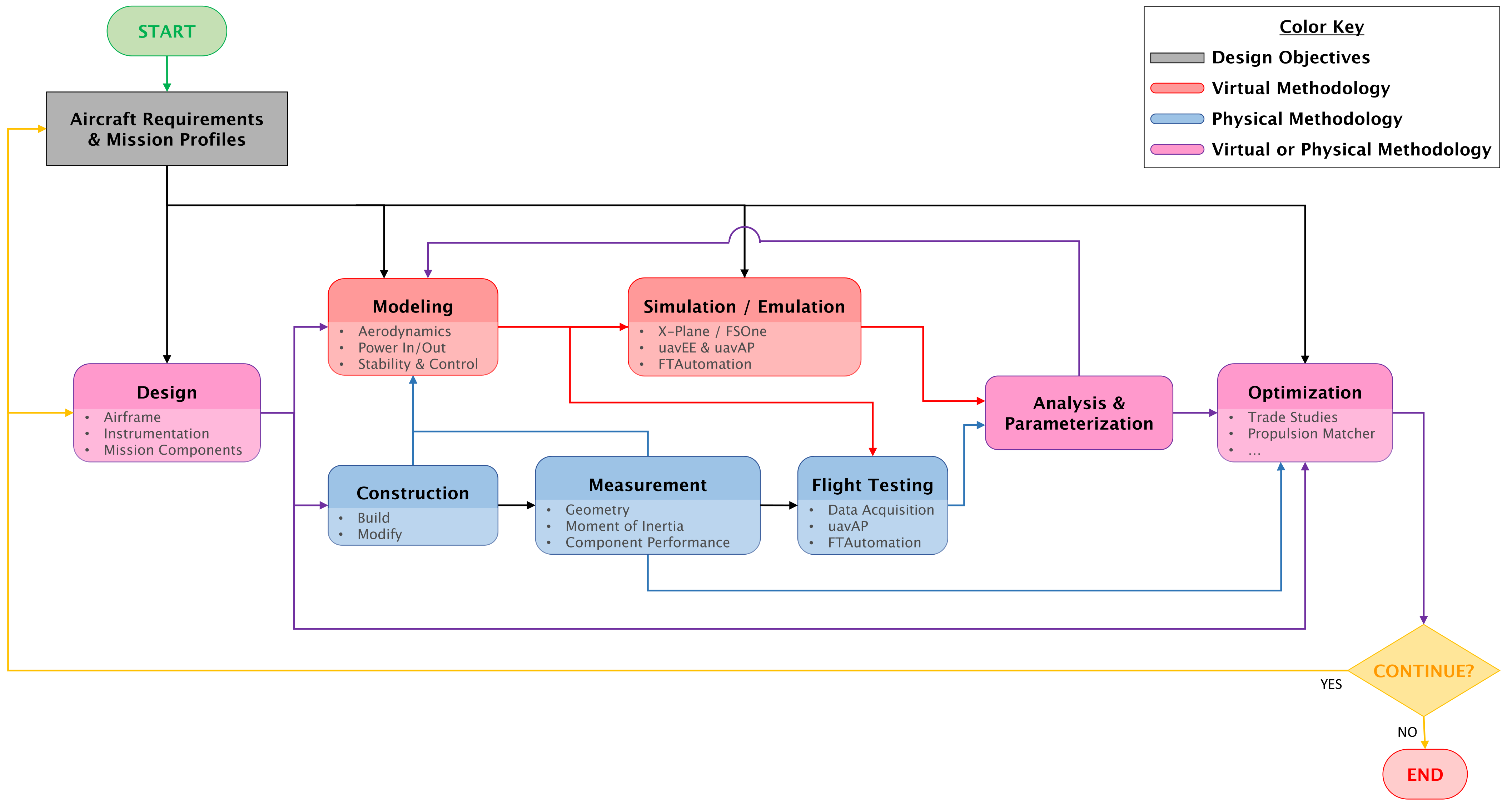
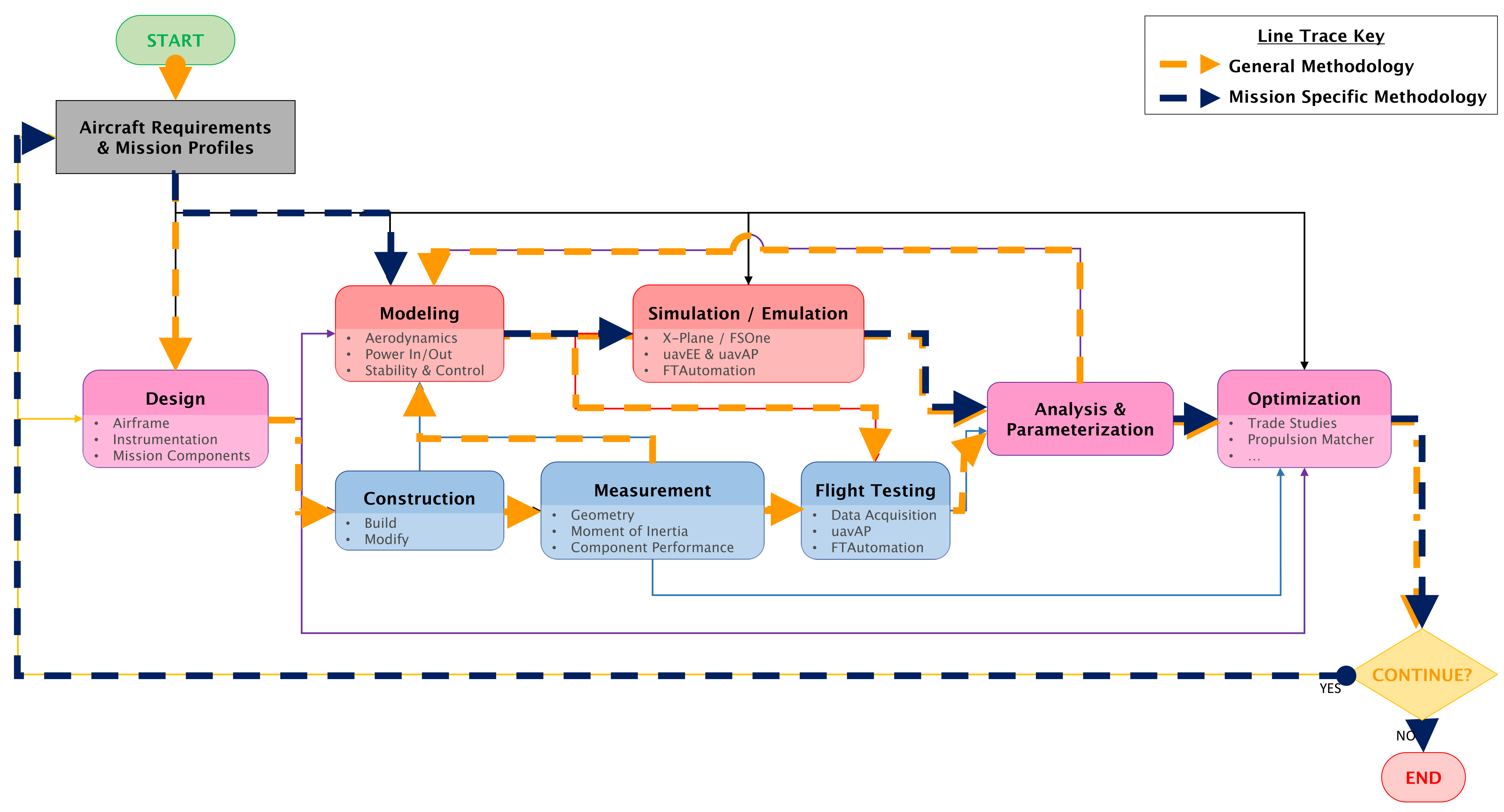
2. Framework
Framework Flow and Iteration
3. Novel and Enhanced Framework Methods and Tools
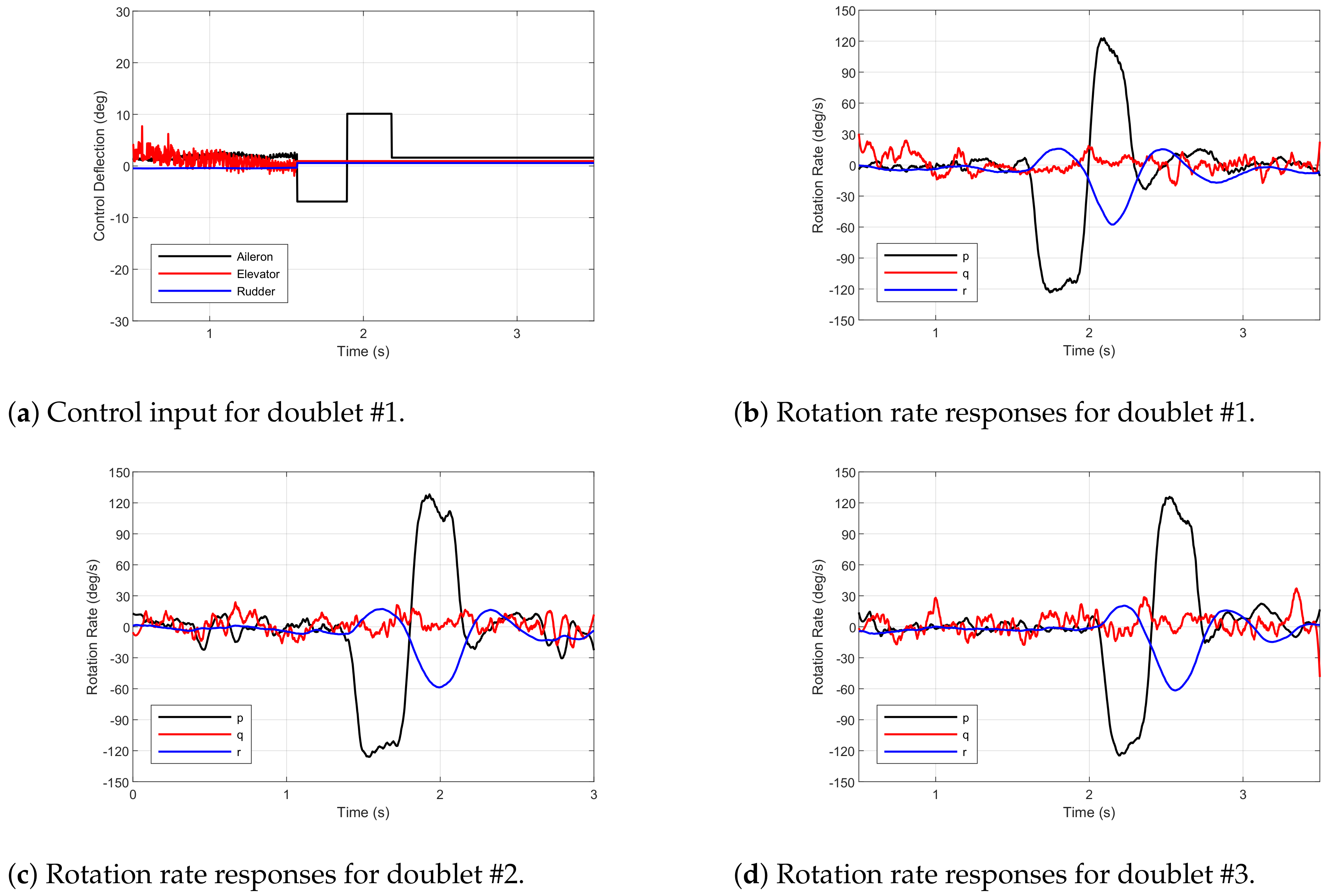
3.1. Flight Testing
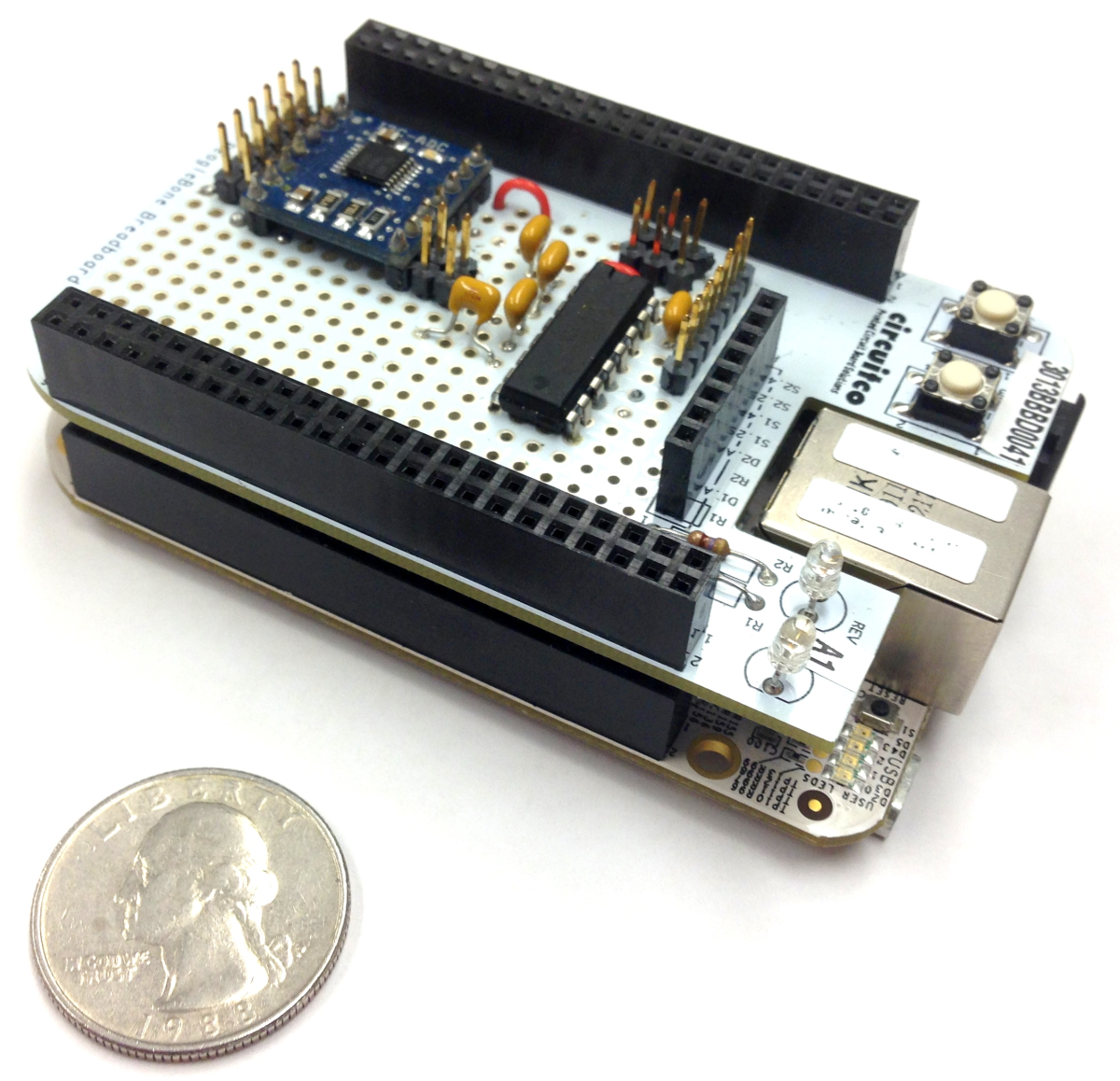
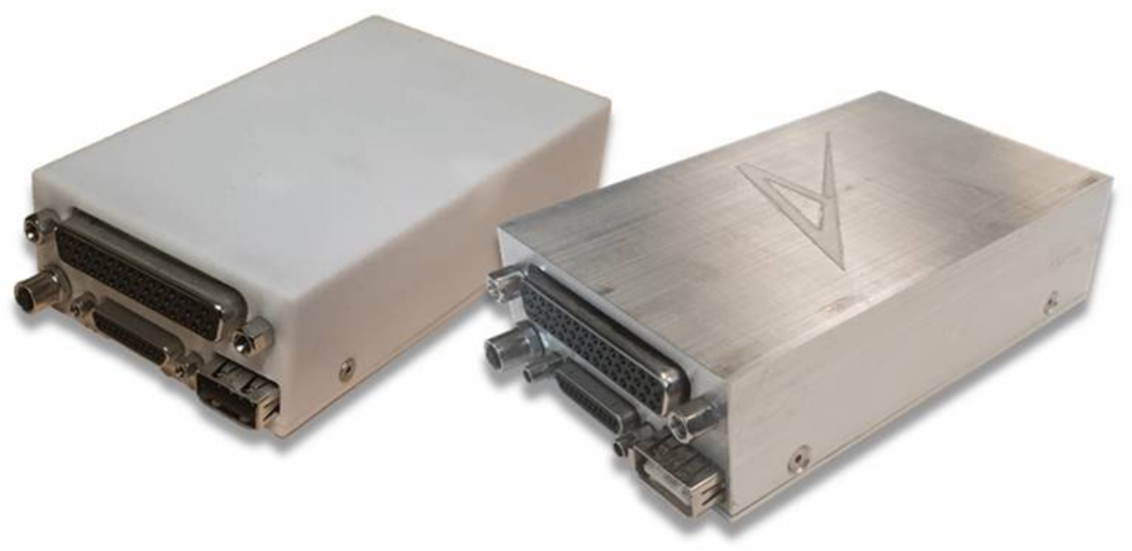
3.1.1. Data Acquisition
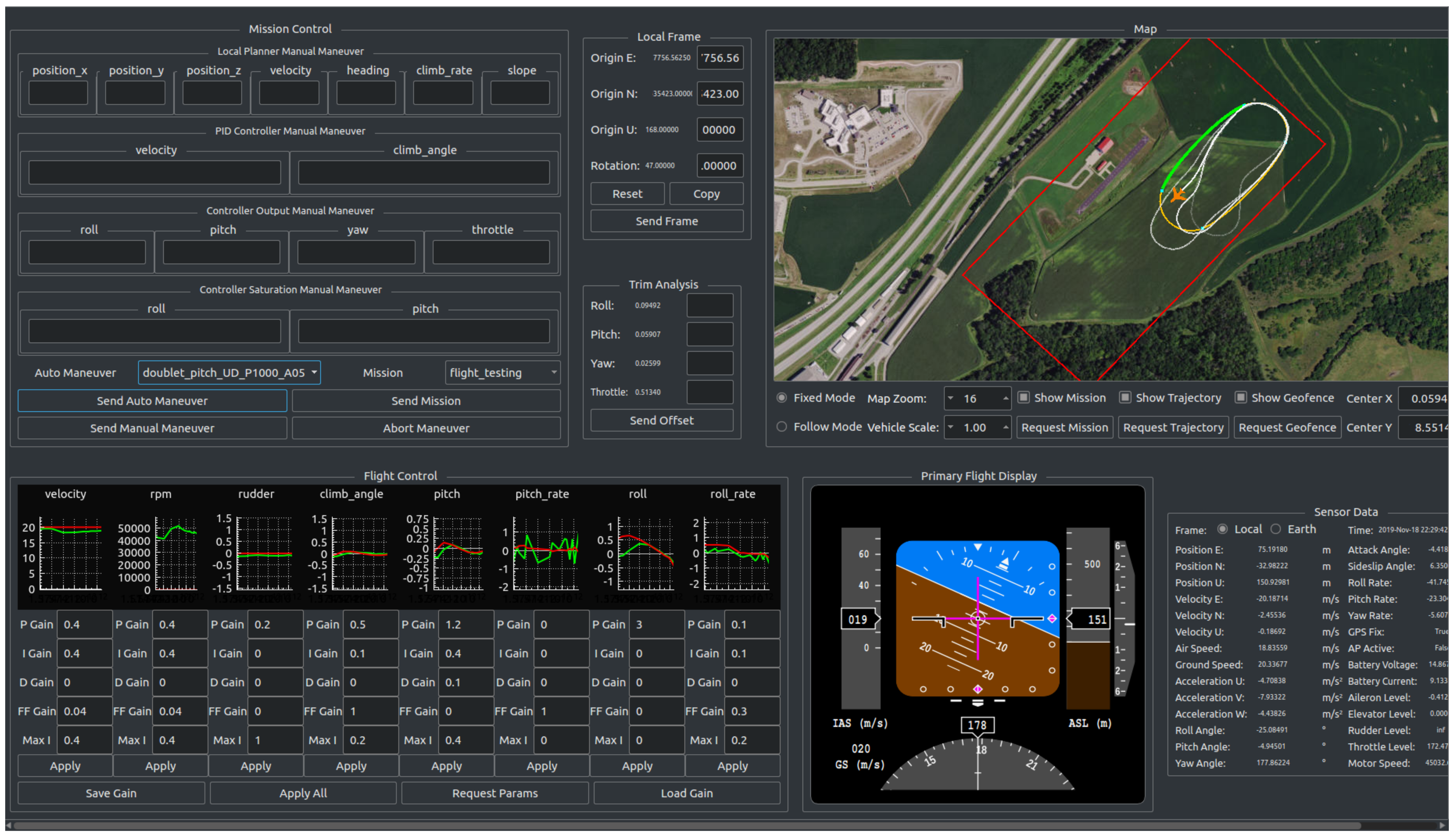
3.1.2. Flight Testing Automation
3.2. Measurement
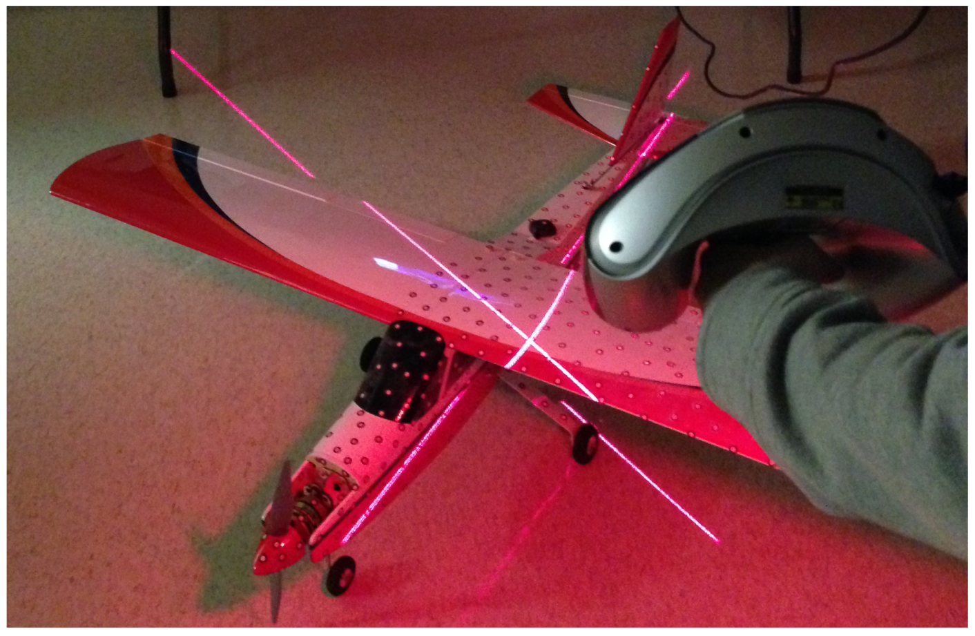
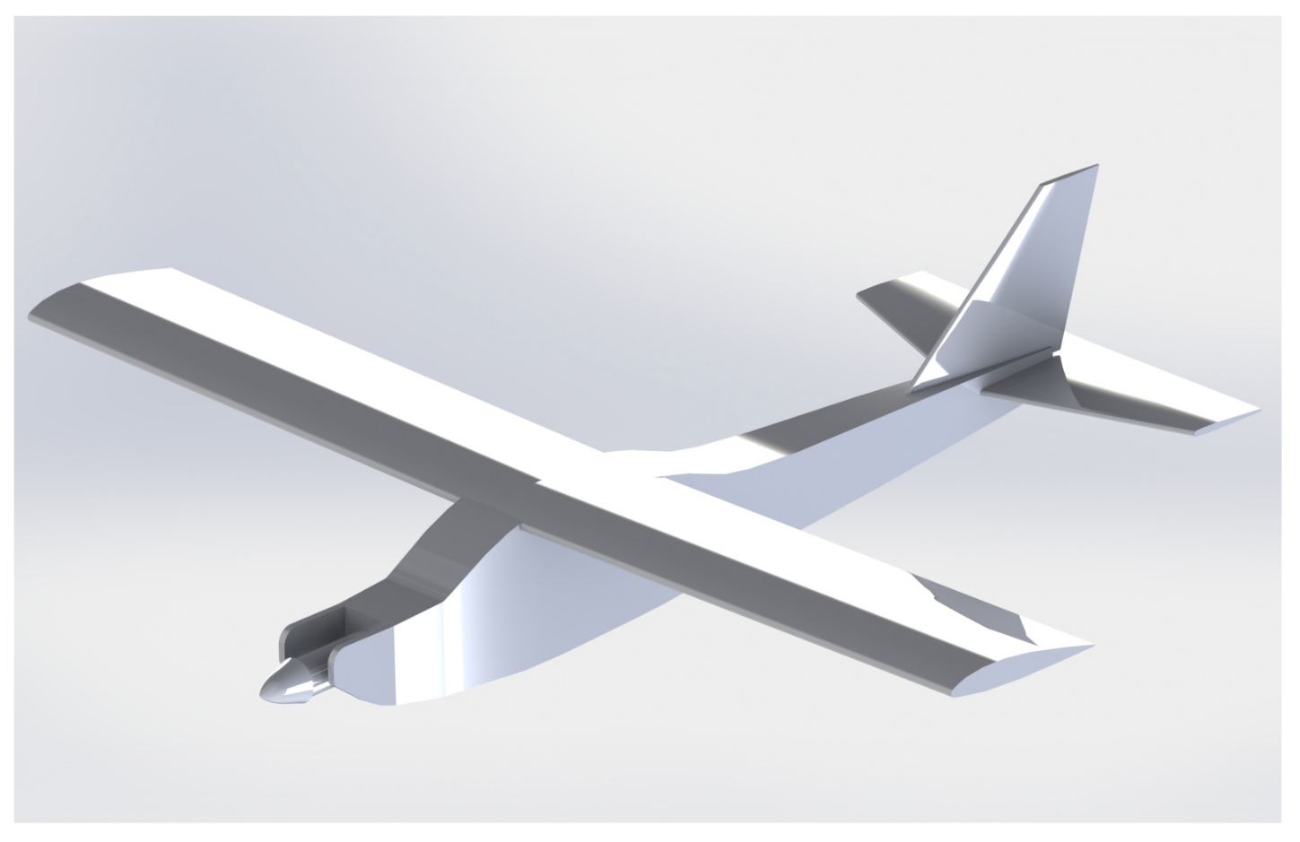
3.2.1. 3D Scanning
3.2.2. Moment of Inertia
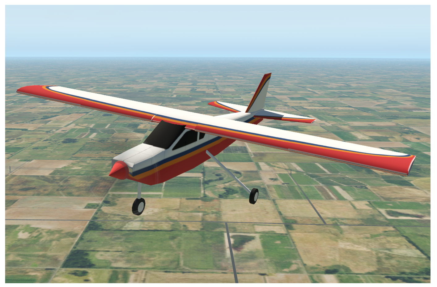
3.3. Modeling and Emulation
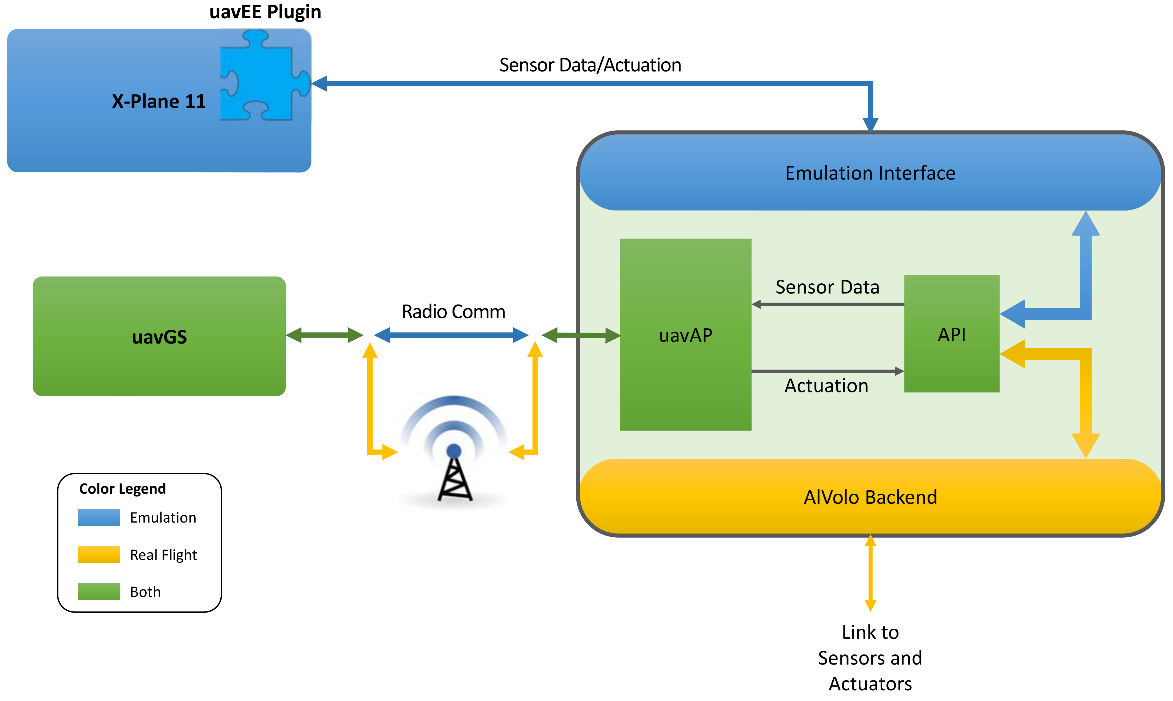
3.3.1. Modular Emulation Environment
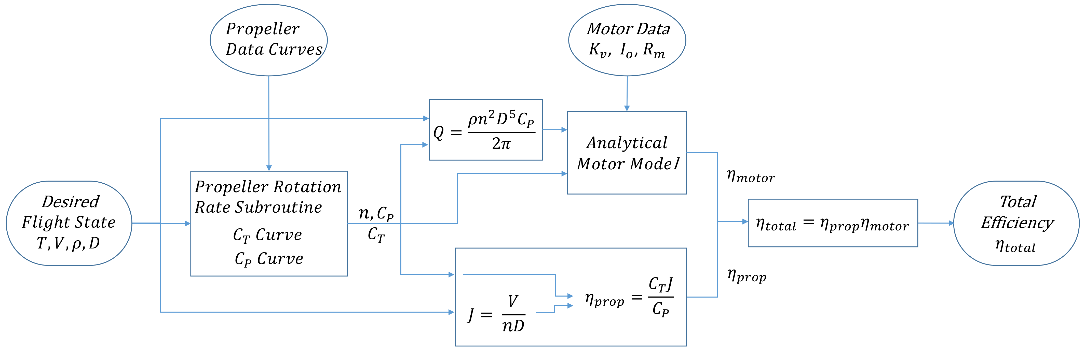
3.3.2. Electric Aircraft Power Consumption Model
3.4. Optimization
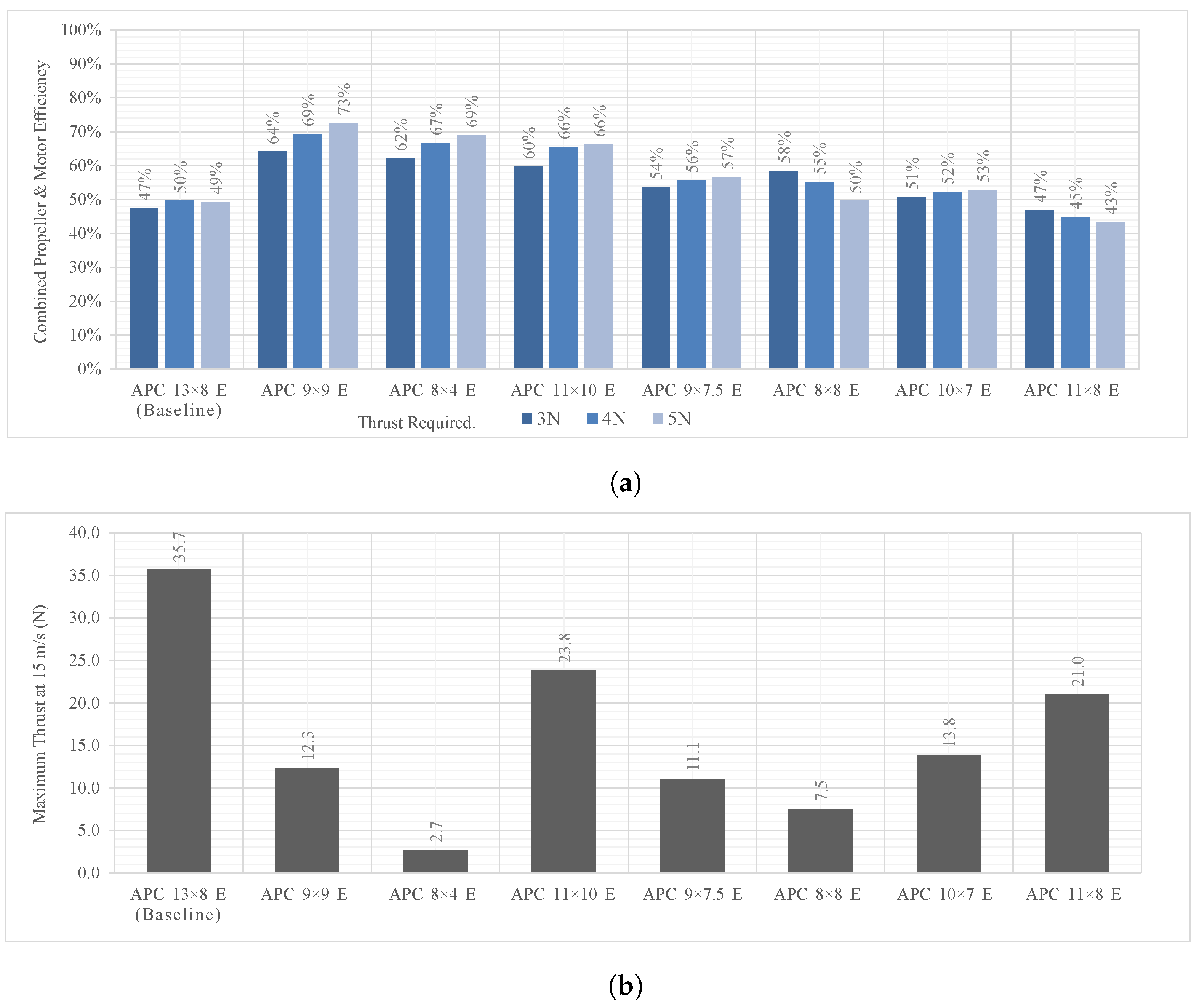
3.4.1. Propulsion System Optimization Tool
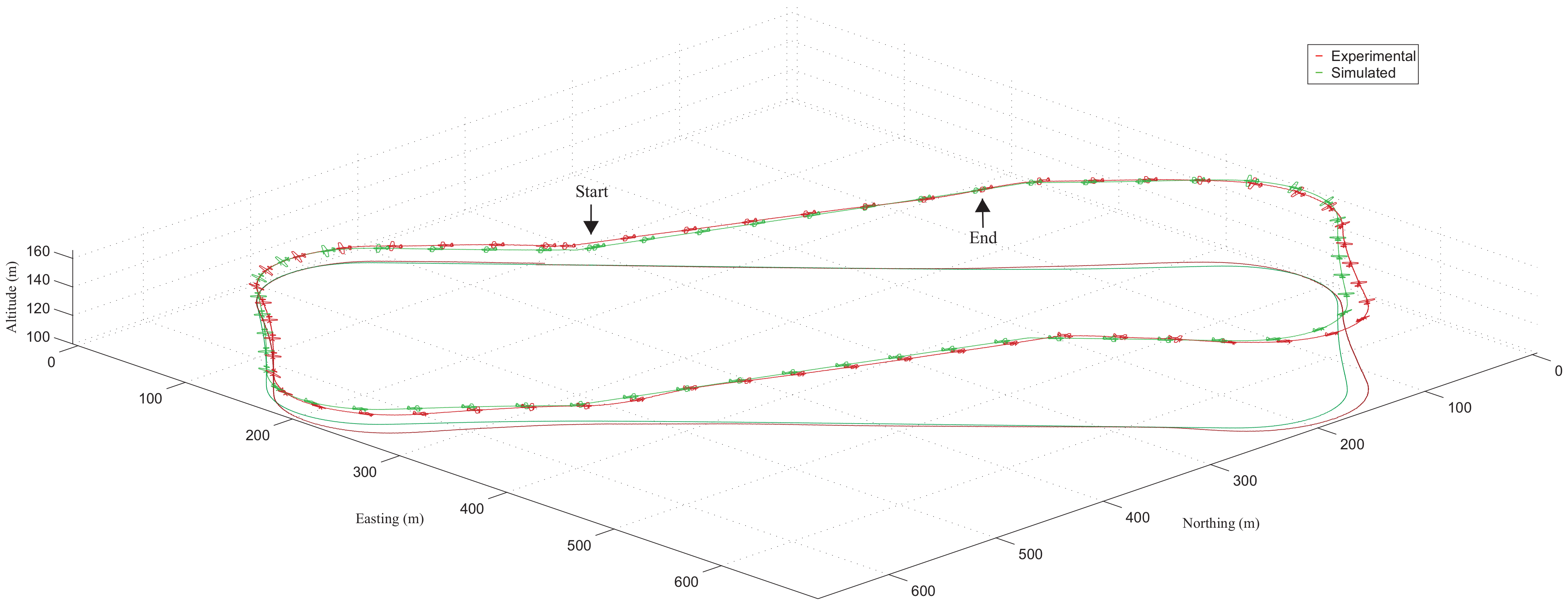
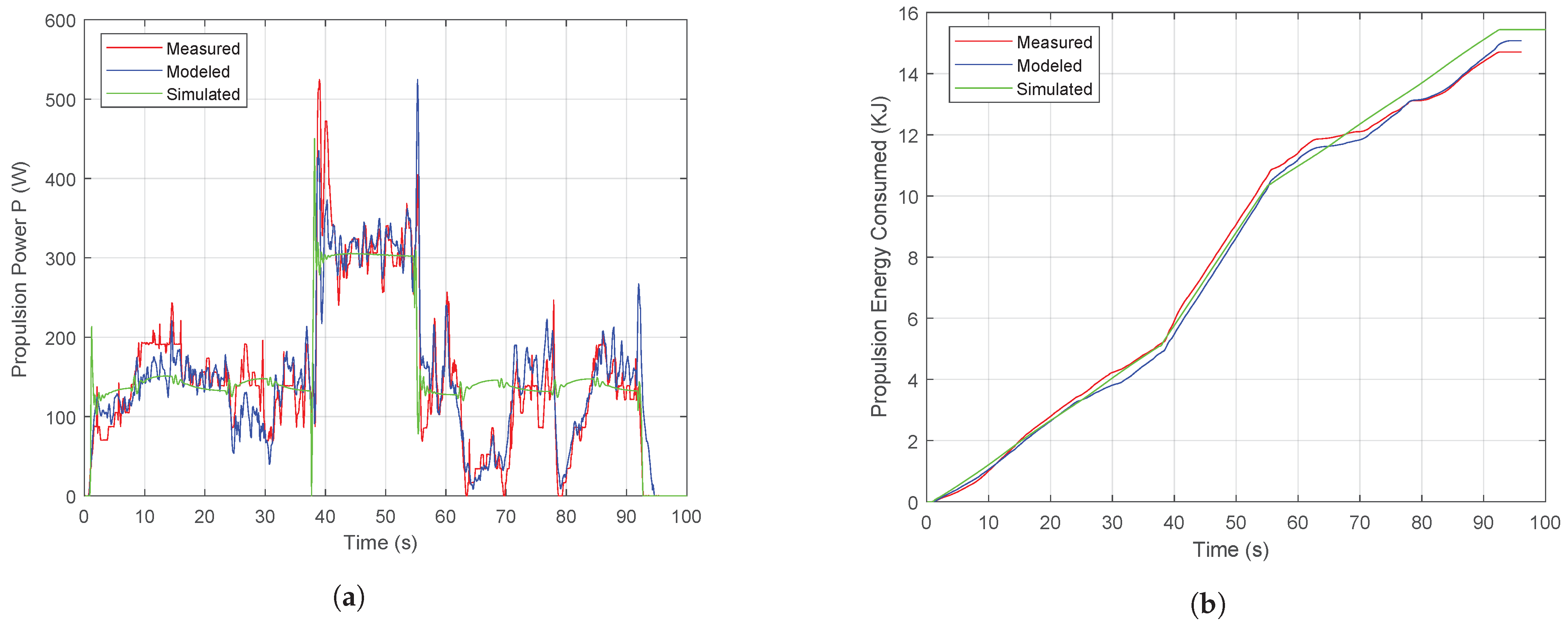
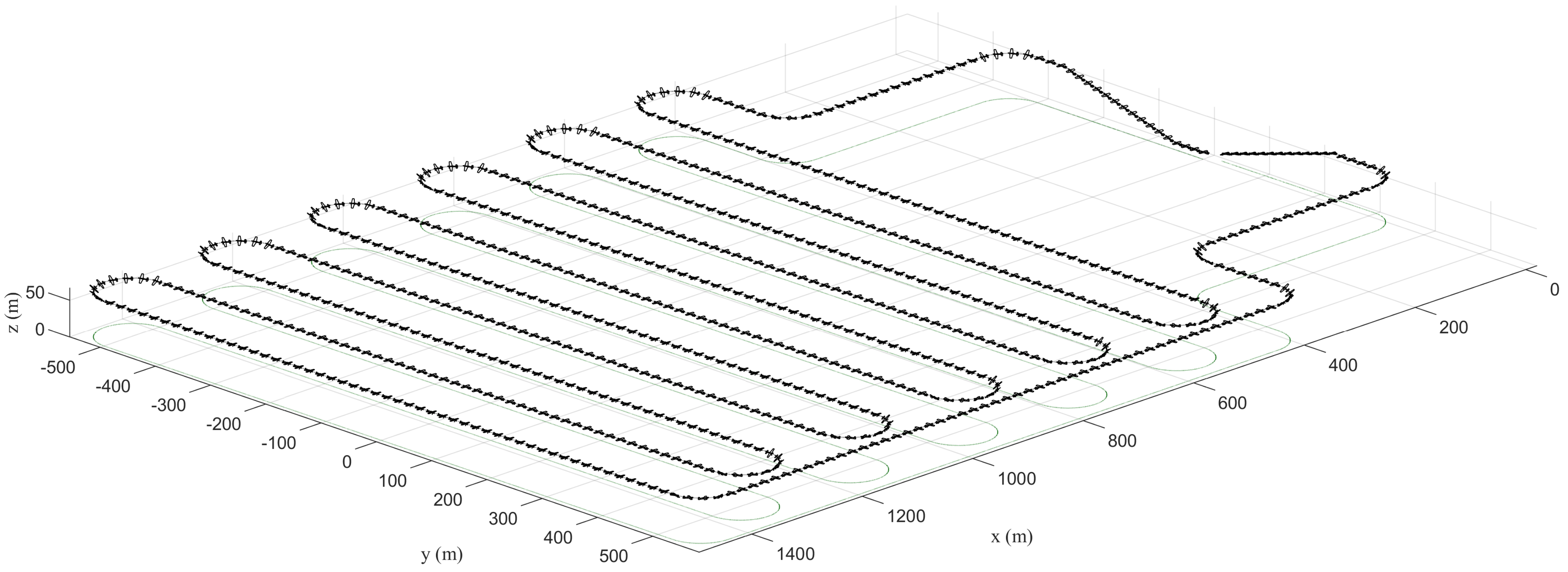
4. Framework Demonstration
4.1. General Methodology
4.2. Mission-Specific Methodology
5. Conclusions
6. Future Work
Author Contributions
Funding
Data Availability Statement
Acknowledgments
Conflicts of Interest
Abbreviations
| ADC | analog-to-digital converter |
| BEMT | blade element momentum theory |
| CAD | computer-aided design |
| CFD | computational fluid dynamics |
| COTS | commercial off-the-shelf |
| DAQ | data acquisition |
| ESC | electronic speed controller |
| GPS | global position system |
| IMU | inertial measurement unit |
| I/O | input/output |
| MDA | multi-discipline analysis |
| MDO | multi-discipline optimization |
| PWM | pulse width modulation |
| UAV | unmanned aerial vehicle |
| VLOS | visual line-of-sight |
References
- Federal Aviation Administration. Integration of Civil Unmanned Aircraft Systems (UAS) in the National Airspace System (NAS) Roadmap, 2nd ed.2018. Available online: https://www.faa.gov/uas/resources/policy_library/media/Second_Edition_Integration_of_Civil_UAS_NAS_Roadmap_July%202018.pdf (accessed on 31 January 2022).
- Lykins, R.; Keshmiri, S. Modal Analysis of 1/3-Scale Yak-54 Aircraft Through Simulation and Flight Testing. In Proceedings of the AIAA Paper 2011-6443, AIAA Atmospheric Flight Mechanics Conference, Portland, OR, USA, 8–11 August 2011. [Google Scholar] [CrossRef]
- Johnson, B.; Lind, R. Characterizing Wing Rock with Variations in Size and Configuration of Vertical Tail. J. Aircr. 2010, 47, 567–576. [Google Scholar] [CrossRef] [Green Version]
- Perry, J.; Mohamed, A.; Johnson, B.; Lind, R. Estimating Angle of Attack and Sideslip Under High Dynamics on Small UAVs. In Proceedings of the ION-GNSS Conference, Savannah, GA, USA, 16–19 September 2008. [Google Scholar]
- Uhlig, D.; Sareen, A.; Sukumar, P.; Rao, A.H.; Selig, M.S. Determining Aerodynamic Characteristics of a Micro Air Vehicle Using Motion Tracking. In Proceedings of the AIAA Paper 2010-8416, AIAA Guidance, Navigation, and Control Conference, Toronto, ON, Canada, 2–5 August 2010. [Google Scholar] [CrossRef]
- Dantsker, O.D.; Selig, M.S. High Angle of Attack Flight of a Subscale Aerobatic Aircraft. In Proceedings of the AIAA Paper 2015-2568, AIAA Applied Aerodynamics Conference, Dallas, TX, USA, 22–26 June 2015. [Google Scholar] [CrossRef] [Green Version]
- Mockli, M. Guidance and Control for Aerobatic Maneuvers of an Unmanned Airplane. Ph.D. Thesis, ETH Zurich, Department of Mechanical and Process Engineering, Zurich, Switzerland, 2006. [Google Scholar]
- Frank, A.; McGrewy, J.S.; Valentiz, M.; Levinex, D.; How, J.P. Hover, Transition, and Level Flight Control Design for a Single-Propeller Indoor Airplane. In Proceedings of the AIAA Paper 2007-6318, AIAA Guidance, Navigation, and Control Conference, Hilton Head, SC, USA, 20–23 August 2007. [Google Scholar] [CrossRef] [Green Version]
- Johnson, E.N.; Wu, A.D.; Neidhoefer, J.C.; Kannan, S.K.; Turbe, M.A. Test Results of Autonomous Airplane Transitions Between Steady-Level and Hovering Flight. J. Guid. Control Dyn. 2008, 31, 358–370. [Google Scholar] [CrossRef] [Green Version]
- Johnson, B.; Lind, R. Trajectory Planning for Sensing Effectiveness with High Angle-of-Attack Flight Capability. In Proceedings of the AIAA Paper 2012-0276, AIAA Aerospace Sciences Meeting, Nashville, TN, USA, 9–12 January 2012. [Google Scholar] [CrossRef]
- Jordan, T.L.; Bailey, R.M. NASA Langley’s AirSTAR Testbed: A Subscale Flight Test Capability for Flight Dynamics and Control System Experiments. In Proceedings of the AIAA Paper 2008-6660, AIAA Atmospheric Flight Mechanics Conference, Honolulu, HI, USA, 18–21 August 2008. [Google Scholar] [CrossRef] [Green Version]
- Ragheb, A.M.; Dantsker, O.D.; Selig, M.S. Stall/Spin Flight Testing with a Subscale Aerobatic Aircraft. In Proceedings of the AIAA Paper 2013-2806, AIAA Applied Aerodynamics Conference, San Diego, CA, USA, 24–27 June 2013. [Google Scholar] [CrossRef]
- Bunge, R.A.; Savino, F.M.; Kroo, I.M. Approaches to Automatic Stall/Spin Detection Based on Small-Scale UAV Flight Testing. In Proceedings of the AIAA Paper 2015-2235, AIAA Atmospheric Flight Mechanics Conference, Dallas, TX, USA, 22–26 June 2015. [Google Scholar] [CrossRef]
- Dantsker, O.D.; Ananda, G.K.; Selig, M.S. GA-USTAR Phase 1: Development and Flight Testing of the Baseline Upset and Stall Research Aircraft. In Proceedings of the AIAA Paper 2017-4078, AIAA Applied Aerodynamics Conference, Denver, CO, USA, 5–9 June 2017. [Google Scholar] [CrossRef] [Green Version]
- Risch, T.; Cosentino, G.; Regan, C.; Kisska, M.; Princen, N. X-48B Flight-Test Progress Overview. In Proceedings of the AIAA Paper 2009-934, AIAA Aerospace Sciences Meeting, Orlando, FL, USA, 5–8 January 2009. [Google Scholar] [CrossRef] [Green Version]
- Lundstrom, D.; Amadori, K. Raven: A Subscale Radio Controlled Business Jet Demonstrator. In Proceedings of the International Congress on the Aeronautical Sciences Systems (ICUAS), Anchorage, AK, USA, 14–19 September 2008. [Google Scholar]
- Regan, C.D.; Taylor, B.R. mAEWing1: Design, Build, Test—Invited. In Proceedings of the AIAA Paper 2016-1747, AIAA Atmospheric Flight Mechanics Conference, San Diego, CA, USA, 4–8 January 2016. [Google Scholar] [CrossRef]
- Regan, C.D. mAEWing2: Conceptual Design and System Test. In Proceedings of the AIAA Paper 2017-1391, AIAA Atmospheric Flight Mechanics Conference, Grapevine, TX, USA, 9–13 January 2017. [Google Scholar] [CrossRef]
- Leong, H.I.; Keshmiri, S.; Jager, R. Evaluation of a COTS Autopilot and Avionics System for UAVs. In Proceedings of the AIAA Paper 2009-1963, AIAA Infotech@Aerospace, Seattle, WA, USA, 6–9 April 2009. [Google Scholar] [CrossRef] [Green Version]
- Esposito, J.F.; Keshmiri, S. Rapid Hardware Interfacing and Software Development for Embedded Devices Using Simulink. In Proceedings of the AIAA Paper 2010-3415, AIAA Infotech@Aerospace, Atlanta, GA, USA, 20–22 April 2010. [Google Scholar] [CrossRef]
- Garcia, G.; Keshmiri, S. Integrated Kalman Filter for a Flight Control System with Redundant Measurements. In Proceedings of the AIAA Paper 2012-2499, AIAA Infotech@Aerospace, Garden Grove, CA, USA, 19–21 June 2012. [Google Scholar] [CrossRef]
- Sobron, A.; Lundström, D.; Staack, I.; Krus, P. Design and Testing of a Low-Cost Flight Control and Data Acquisition System for Unstable Subscale Aircraft. In Proceedings of the International Congress on the Aeronautical Sciences Systems, Daejeon, Korea, 27–29 September 2016. [Google Scholar]
- Theile, M.; Dantsker, O.D.; Caccamo, M.; Yu, S. uavAP: A Modular Autopilot Framework for UAVs. In Proceedings of the AIAA Paper 2020-3268, AIAA Aviation 2020 Forum, Virtual Event, 15–19 June 2020. [Google Scholar] [CrossRef]
- Sukumar, P.P.; Selig, M.S. Dynamic Soaring of Sailplanes over Open Fields. J. Aircr. 2013, 50, 1420–1430. [Google Scholar] [CrossRef] [Green Version]
- Woodbury, T.; Dunn, C.; Valasek, J. Autonomous Soaring Using Reinforcement Learningfor Trajectory Generation. In Proceedings of the AIAA Paper 2014-0990, AIAA SciTech Forum, National Harbor, MD, USA, 13–17 January 2014. [Google Scholar] [CrossRef] [Green Version]
- Depenbusch, N.T.; Bird, J.J.; Langelaan, J.W. The AutoSOAR autonomous soaring aircraft, part 1: Autonomy algorithms. J. Field Robot. 2016. [Google Scholar] [CrossRef]
- Sachs, G.; Gruter, B. Maximum TravelSpeed Performance of Albatrossesand UAVs Using Dynamic Soaring. In Proceedings of the AIAA Paper 2019-0568, AIAA SciTech Forum, San Diego, CA, USA, 7–11 January 2019. [Google Scholar] [CrossRef]
- Bird, J.J.; Langelaan, J.W. Optimal Speed Scheduling for Hybrid Solar Aircraft with Arrival Time Condition. In Proceedings of the AIAA Paper 2019-1421, AIAA SciTech Forum, San Diego, CA, USA, 7–11 January 2019. [Google Scholar] [CrossRef]
- Brandt, S.A.; Stiles, R.J.; Bertin, J.J.; Whitford, R. Introduction to Aeronautics: A Design Perspective, 3rd ed.; American Institute of Aeronautics and Astronautics, Inc.: Reston, VA, USA, 2015. [Google Scholar]
- Howe, D. Aircraft Conceptual Design Synthesis; Professional Engineering Publishing Limited: Suffolk, UK, 2000. [Google Scholar]
- Kundu, A.K. Aircraft Design; Cambridge University Press: Cambridge, UK, 2012. [Google Scholar]
- McMasters, J.; Cummings, R. Rethinking the Airplane Design Process—An Early 21st Century Perspective. In Proceedings of the AIAA Paper 2004-693, AIAA Aerospace Sciences Meeting, Reno, NV, USA, 5–8 January 2004. [Google Scholar] [CrossRef]
- Nicolai, L.M.; Carichner, G.E. Fundamentals of Aircraft and Airship Design: Volume I— Aircraft Design; American Institute of Aeronautics and Astronautics, Inc.: Reston, VA, USA, 1975. [Google Scholar]
- Roskam, J. Aircraft Design 1–8 Set, 2nd ed.; Darcorporation: Lawrence, KS, USA, 2003. [Google Scholar]
- Sadraey, M.H. Aircraft Design: A Systems Engineering Approach; John Wiley & Sons: West Sussex, UK, 2013. [Google Scholar]
- Torenbeek, E. Synthesis of Subsonic Airplane Design; Delft University Press: Delft, The Netherlands, 1982. [Google Scholar]
- Fielding, J.P. Introduction to Aircraft Design; Cambridge University Press: Cambridge, UK, 1999. [Google Scholar]
- Keane, A.J.; Sóbester, A.; Scanlan, J.P. Small Unmanned Fixed-Wing Aircraft Design: A Practical Approach; John Wiley & Sons: West Sussex, UK, 2017. [Google Scholar]
- Raymer, D.P. Aircraft Design: A Conceptual Approach, 5th ed.; American Institute of Aeronautics and Astronautics, Inc.: Reston, VA, USA, 2012. [Google Scholar]
- Davenport, C. Virgin Galactic’s Quest for Space; The Washington Post: Washington, DC, USA, 2018. [Google Scholar]
- Stevenson, B. Virgin Galactic seeks ‘year of rebirth’. Flight Int. 2015, 187, 10. [Google Scholar]
- Raymer, D.P. Enhancing Aircraft Conceptual Design Using Multidisciplinary Optimization. Ph.D. Thesis, Swedish Royal Institute of Technology (KTH), Department of Aeronautics, Stockholm, Sweden, 2002. [Google Scholar]
- Mainini, L.; Maggiore, P. Multidisciplinary Integrated Framework for the Optimal Design of a Jet Aircraft Wing. Int. J. Aerosp. Eng. 2012, 2012, 750642. [Google Scholar] [CrossRef]
- Magnussen, O.; Hovland, G.; Ottestad, M. Multicopter UAV design optimization. In Proceedings of the IEEE International Conference on Mechatronic and Embedded Systems and Applications (MESA), Senigallia, Italy, 10–12 September 2014. [Google Scholar] [CrossRef]
- Oktay, T.; Konar, M.; Onay, M.; Aydin, M.; Mohamed, M.A. Simultaneous small UAV and autopilot system design. Aircr. Eng. Aerosp. Technol. 2016, 88, 818–834. [Google Scholar] [CrossRef]
- Fujiwara, G.E.C.; Bragg, M.B. Optimization of Variable-Camber Continuous Trailing-Edge Flap Configuration for Drag Reduction. J. Aircr. Mar. 2019, 56, 730–746. [Google Scholar] [CrossRef]
- Maldonado, V.; Santos, D.; Wilt, M.; Ramirez, D.; Shoemaker, J.; Ayele, W.; Beeson, B.; Lisby, B.; Zamora, J.; Antu, C. ‘Switchblade’: Wide-Mission Performance Design of a Multi-Variant Unmanned Aerial System. In Proceedings of the AIAA Paper 2021-0213, AIAA SciTech Forum, Virtual Event, 11–15 January 2021. [Google Scholar] [CrossRef]
- Kennedy, B.M.; Sobek, D.K.; Kennedy, M.N. Reducing rework by applying set-based practices early in the systems engineering process. Syst. Eng. 2013, 17, 278–296. [Google Scholar] [CrossRef] [Green Version]
- Lundstrom, D.; Amadori, K.; Krus, P. Automation of Design and Prototyping of Micro Aerial Vehicle. In Proceedings of the AIAA Paper 2009-629, AIAA Aerospace Sciences Meeting, Orlando, FL, USA, 5–8 January 2009. [Google Scholar] [CrossRef] [Green Version]
- Lundstrom, D. Aircraft Design Automation and Subscale Testing. Ph.D. Thesis, Linkoping University, Department of Management and Engineering, Linkoping, Sweden, 2012. [Google Scholar]
- Dantsker, O.D.; Imtiaz, S.; Caccamo, M. Electric Propulsion System Optimization for a Long-Endurance Unmanned Aircraft. In Proceedings of the AIAA Paper 2019-4486, AIAA/IEEE Electric Aircraft Technologies Symposium, Indianapolis, IN, USA, 22–24 August 2019. [Google Scholar] [CrossRef]
- Dantsker, O.D.; Theile, M.; Caccamo, M. A High-Fidelity, Low-Order Propulsion Power Model for Fixed-Wing Electric Unmanned Aircraft. In Proceedings of the AIAA Paper 2018-5009, AIAA/IEEE Electric Aircraft Technologies Symposium, Cincinnati, OH, USA, 9–11 July 2018. [Google Scholar] [CrossRef]
- Laminar Research. X-Plane 11. Available online: http://www.x-plane.com/ (accessed on 31 January 2022).
- InertiaSoft, Inc. FS One RC Flight Simulator. Available online: http://www.fsone.com/ (accessed on 31 January 2022).
- Dantsker, O.D.; Yu, S.; Vahora, M.; Caccamo, M. Flight Testing Automation to Parameterize Unmanned Aircraft Dynamics. In Proceedings of the AIAA Paper 2019-3230, AIAA Aviation and Aeronautics Forum and Exposition, Dallas, TX, USA, 17–21 June 2019. [Google Scholar] [CrossRef]
- Dantsker, O.D.; Deters, R.W.; Caccamo, M. Propulsion System Testing for a Long-Endurance Solar-Powered Unmanned Aircraft. In Proceedings of the AIAA Paper 2019-3688, AIAA Applied Aerodynamics Conference, Dallas, TX, USA, 17–21 June 2019. [Google Scholar] [CrossRef] [Green Version]
- Dantsker, O.D.; Vahora, M.; Imtiaz, S.; Caccamo, M. High Fidelity Moment of Inertia Testing of Unmanned Aircraft. In Proceedings of the AIAA Paper 2018-4219, AIAA Applied Aerodynamics Conference, Atlanta, GA, USA, 25–29 June 2018. [Google Scholar] [CrossRef] [Green Version]
- Mancuso, R.; Dantsker, O.D.; Caccamo, M.; Selig, M.S. A Low-Power Architecture for High Frequency Sensor Acquisition in Many-DOF UAVs. In Proceedings of the International Conference on Cyber-Physical Systems, Berlin, Germany, 14–17 April 2014. [Google Scholar] [CrossRef]
- Dantsker, O.D.; Mancuso, R.; Selig, M.S.; Caccamo, M. High-Frequency Sensor Data Acquisition System (SDAC) for Flight Control and Aerodynamic Data Collection Research on Small to Mid-Sized UAVs. In Proceedings of the AIAA Paper 2014-2565, AIAA Applied Aerodynamics Conference, Atlanta, GA, USA, 16–20 June 2014. [Google Scholar] [CrossRef] [Green Version]
- Dantsker, O.D.; Caccamo, M.; Vahora, M.; Mancuso, R. Flight & Ground Testing Data Set for an Unmanned Aircraft: Great Planes Avistar Elite. In Proceedings of the AIAA Paper 2020-0780, AIAA SciTech Forum; Orlando, FL, USA, 6–10 January 2020, 2020. [Google Scholar] [CrossRef]
- Al Volo LLC. Al Volo: Flight Systems. Available online: http://www.alvolo.us (accessed on 31 January 2022).
- Dantsker, O.D.; Mancuso, R. Flight Data Acquisition Platform Development, Integration, and Operation on Small- to Medium-Sized Unmanned Aircraft. In Proceedings of the AIAA Paper 2019-1262, AIAA SciTech Forum, San Diego, CA, USA, 7–11 January 2019. [Google Scholar] [CrossRef] [Green Version]
- Canin, D.G.; McConnell, J.K.; James, P.W. F-35 High Angle of Attack Flight Control Development and Flight Test Results. In Proceedings of the AIAA Paper 2019-3227, AIAA Aviation and Aeronautics Forum and Exposition, Dallas, TX, USA, 17–21 June 2019. [Google Scholar] [CrossRef]
- Qadri, M.; Vahora, M.; Hascaryo, R.; Finlon, S.; Dantsker, O.D.; Ananda, G.K.; Selig, M.S. Undergraduate Contribution to Dynamically Scaled General Aviation Research at the University of Illinois at Urbana-Champaign. In Proceedings of the AIAA Paper 2018-1069, AIAA Aerospace Sciences Meeting, Kissimmee, FL, USA, 8–12 January 2018. [Google Scholar] [CrossRef]
- Kimberlin, R.D. Flight Testing of Fixed-Wing Aircraft; AIAA Education Series; AIAA: Reston, VA, USA, 2003. [Google Scholar]
- McCormick, B.W. Introduction to Flight Testing and Applied Aerodynamics; AIAA Education Series; AIAA: Reston, VA, USA, 2011. [Google Scholar]
- Ward, D.T.; Strganac, T.W. Introduction to Flight Test Engineering, 2nd ed.; Kendall/Hunt Publishing Company: Dubuque, IA, USA, 2001. [Google Scholar]
- Arent, L.; Falatko, J. 757 fly-by-wire demonstrator flight test. In Proceedings of the AIAA Paper 1992-4099, 6th AIAA Biennial Flight Test Conference, Hilton Head, SC, USA, 24–26 August 1992. [Google Scholar] [CrossRef]
- Brandon, J.M.; Morelli, E.A. Real-Time Onboard Global Nonlinear Aerodynamic Modeling from Flight Data. In Proceedings of the AIAA Paper 2014-2554, AIAA Atmospheric Flight Mechanics Conference, Atlanta, GA, USA, 16–20 June 2014. [Google Scholar] [CrossRef] [Green Version]
- Larsson, R.; Sobron, A.; Lundström, D.; Enqvist, M. A Method for Improved Flight Testing of Remotely Piloted Aircraft Using Multisine Inputs. Aerospace 2020, 7, 135. [Google Scholar] [CrossRef]
- Roessler, C.; Stahl, P.; Sendner, F.; Hermanutz, A.; Koeberle, S.; Bartasevicius, J.; Rozov, V.; Breitsamter, C.; Hornung, M.; Meddaikar, Y.M.; et al. Aircraft Design and Testing of FLEXOP Unmanned Flying Demonstrator to Test Load Alleviation and Flutter Suppression of High Aspect Ratio Flexible Wings. In Proceedings of the AIAA Paper 2019-1813, AIAA SciTech Forum, San Diego, CA, USA, 7–11 January 2019. [Google Scholar] [CrossRef]
- Federal Aviation Administration, U.S. Department of Transportation. SUMMARY OF SMALL UNMANNED AIRCRAFT RULE (PART 107). Available online: https://www.faa.gov/uas/media/Part_107_Summary.pdf (accessed on 31 January 2022).
- Dorobantu, A.; Johnson, W.; Lie, F.A.; Taylor, B.; Murch, A.; Paw, Y.C.; Gebre-Egziabher, D.; Balas, G. An airborne experimental test platform: From theory to flight. In Proceedings of the 2013 American Control Conference, Washington, DC, USA, 17–19 June 2013; pp. 659–673. [Google Scholar] [CrossRef]
- Sobron, A.; Lundström, D.; Larsson, R.; Krus, P.; Jouannet, C. Methods For Efficient Flight Testing And Modelling Of Remotely Piloted Aircraft within Visual Line-of-Sight. In Proceedings of the International Congress on the Aeronautical Sciences Systems, Belo Horizonte, Brazil, 9–14 September 2018. [Google Scholar]
- Stahl, P.; Sendner, F.M.; Hermanutz, A.; Rößler, C.; Hornung, M. Mission and Aircraft Design of FLEXOP Unmanned Flying Demonstrator to Test Flutter Suppression within Visual Line of Sight. In Proceedings of the AIAA Paper 2017-3766, AIAA Aviation Technology, Integration, and Operations Conference, Denver, CO, USA, 5–9 June 2017. [Google Scholar] [CrossRef] [Green Version]
- Arifianto, O.; Farhood, M. Development and Modeling of a Low-Cost Unmanned Aerial Vehicle Research Platform. J. Intell. Robot. Syst. 2015, 80, 139–164. [Google Scholar] [CrossRef]
- Sanders, F.C.; Tischler, M.; Berger, T.; Berrios, M.G.; Gong, A. System Identification and Multi-Objective Longitudinal Control Law Design for a Small Fixed-Wing UAV. In Proceedings of the AIAA Paper 2018-0296, AIAA Atmospheric Flight Mechanics Conference, Kissimmee, FL, USA, 8–12 January 2018. [Google Scholar] [CrossRef]
- Murch, A. A Flight Control System Architecture for the NASA AirSTAR Flight Test Infrastructure. In Proceedings of the AIAA Paper 2008-6990, AIAA Guidance, Navigation and Control Conference, Honolulu, HI, USA, 18–21 August 2008. [Google Scholar] [CrossRef] [Green Version]
- Napolitano, M.R. Development, Instrumentation, and Flight Testing of UAVs as Research Platforms for Flight Control Systems Research. Available online: http://www.dsea.unipi.it/Members/polliniw/sgn/sem_napolitano1 (accessed on 19 March 2013).
- Reiss, P.; Dollinger, D.; Schropp, C.; Löbl, D.; Holzapfel, F. Multi Crew Coordination for Remote Piloted Transition VTOL. In Proceedings of the AIAA Paper 2021-1056, AIAA Scitech 2021 Forum, Virtual Forum, 11–21 January 2021. [Google Scholar] [CrossRef]
- Sobron, A.; Lundström, D.; Krus, P. A Review of Current Research in Subscale Flight Testing and Analysis of Its Main Practical Challenges. Aerospace 2021, 8, 74. [Google Scholar] [CrossRef]
- Factory, U. UAV Factory|Education. Available online: https://uavfactory.com/en/education (accessed on 31 January 2022).
- Bunge, R.A.; Savino, F.M.; Kroo, I.M. Stall/Spin Flight Test Techniques with COTS Model Aircraft and Flight Data Systems. In Proceedings of the AIAA Paper 2015-3225, AIAA Flight Testing Conference, Dallas, TX, USA, 22–26 June 2015. [Google Scholar] [CrossRef]
- Dantsker, O.D. Determining Aerodynamic Characteristics of an Unmanned Aerial Vehicle using a 3D Scanning Technique. In Proceedings of the AIAA Paper 2015-0026, AIAA Aerospace Sciences Meeting, Kissimmee, FL, USA, 5–9 January 2015. [Google Scholar] [CrossRef]
- ZCorporation. The New ZScanner 800. Available online: www.zcorp.com/documents/182_ZScanner800-tearsheet-v05wb.pdf (accessed on 12 March 2013).
- UIUC Applied Aerodynamics Group. UIUC Airfoil Coordinates Database. Available online: http://aerospace.illinois.edu/m-selig/ads/coord_database.html (accessed on 31 January 2022).
- Dantsker, O.D.; Vahora, M. Comparison of Aerodynamic Characterization Methods for Design of Unmanned Aerial Vehicles. In Proceedings of the AIAA Paper 2018-0272, AIAA Aerospace Sciences Meeting, Kissimmee, FL, USA, 8–12 January 2018. [Google Scholar] [CrossRef]
- Koeberle, S.J.; Albert, A.E.; Nagel, L.H.; Hornung, M. Flight Testing for Flight Dynamics Estimation of Medium-Sized UAVs. In Proceedings of the AIAA Paper 2021-1526, AIAA SciTech Forum, Virtual Event, 11–21 January 2021. [Google Scholar] [CrossRef]
- Miller, M.P. An Accurate Method of Measuring the Moments of Inertia of Airplanes, 1930. National Advisory Committee for Aeronautics, Technical Note 351. Available online: https://ntrs.nasa.gov/citations/19930081105 (accessed on 31 January 2022).
- Soule, H.; Miller, M.P. The Experimental Determination of the Moments of Inertia of Airplanes, 1934. National Advisory Committee for Aeronautics, Technical Note 467. Available online: https://ntrs.nasa.gov/citations/19930091541 (accessed on 31 January 2022).
- Gracey, W. The Experimental Determination of the Moments of Inertia of Airplanes by a Simplified Compound -Pendulum Method, 1948. National Advisory Committee for Aeronautics, Technical Note 1629. Available online: https://ntrs.nasa.gov/citations/19930082299 (accessed on 31 January 2022).
- Turner, H.L. Measurement of the Moments of Inertia of an Airplane by a Simplified Method, 1950. National Advisory Committee for Aeronautics, Technical Note 2201. Available online: https://ntrs.nasa.gov/citations/19930082849 (accessed on 31 January 2022).
- de Jong, R.C.; Mulder, J.A. Accurate Estimation of Aircraft Inertia Characteristics from a Single Suspension Experiment. J. Aircr. 1987, 24, 362–370. [Google Scholar] [CrossRef]
- Jardin, M.; Mueller, E. Optimized Measurements of UAV Mass Moment of Inertia with a Bifilar Pendulum. In Proceedings of the AIAA Paper 2007-6822, AIAA Guidance, Navigation, and Control Conference, Hilton Head, SC, USA, 20–23 August 2007. [Google Scholar] [CrossRef]
- Bowman, A.; Barnes, G.; Keshmiri, S. An Empirical Method for Estimating Moments of Inertia of Light Unmanned Air Vehicles. In Proceedings of the AIAA Paper 2012-2598, AIAA Infotech@Aerospace, Garden Grove, CA, USA, 19–21 June 2012. [Google Scholar] [CrossRef]
- Mendes, A.; van Kampen, E.; Remes, B.; Chu, Q. Determining moments of inertia of small UAVs: A comparative analysis of an experimental method versus theoretical approaches. In Proceedings of the AIAA Paper 2012-4463, AIAA Guidance, Navigation and Control Conference, Minneapolis, MN, USA, 13–16 August 2012. [Google Scholar] [CrossRef]
- Lehmkühler, K.; Wong, K.; Verstraete, D. Methods for accurate measurements of small fixed wing UAV inertial properties. Aeronaut. J. 2016, 120, 1785–1811. [Google Scholar] [CrossRef]
- McCormick, B.W. Aerodynamics, Aeronautics, and Flight Mechanics; Wiley: Hoboken, NJ, USA, 1994. [Google Scholar]
- Pieper, K.; Perry, A.; Ansell, P.; Bretl, T. Design and Development of a Dynamically Scaled Distributed Electric Propulsion Aircraft Testbed. In Proceedings of the AIAA Paper 2018-4996, AIAA/IEEE Electric Aircraft Technologies Symposium, Cincinnati, OH, USA, 9–11 July 2018. [Google Scholar] [CrossRef]
- Theile, M.; Dantsker, O.D.; Nai, R.; Caccamo, M. uavEE: A Modular, Power-Aware Emulation Environment for Rapid Prototyping and Testing of UAVs. In Proceedings of the IEEE International Conference on Embedded and Real-Time Computing Systems and Applications, Hakodate, Japan, 28–31 August 2018. [Google Scholar] [CrossRef]
- National Science Foundation. Award Abstract 1932529: CPS: Medium: Collaborative Research: Virtual Sully: Autopilot with Multilevel Adaptation for Handling Large Uncertainties. Available online: https://www.nsf.gov/awardsearch/showAward?AWD_ID=1932529&HistoricalAwards=falsel (accessed on 31 January 2022).
- Ponniah, J.; Yee, A.K.; Dantsker, O.D.; Yu, S.; Mancuso, R. Design of Multi-Agent UAV Simulator to Support the Development of the MARSNet Communication Protocol. In Proceedings of the AIAA Paper 2019-3114, AIAA Aviation and Aeronautics Forum and Exposition, Dallas, TX, USA, 17–21 June 2019. [Google Scholar] [CrossRef]
- Lee, J.S.; Yu, K.H. Optimal Path Planning of Solar-Powered UAV Using Gravitational Potential Energy. IEEE Trans. Aerosp. Electron. Syst. 2017, 53, 1442–1451. [Google Scholar] [CrossRef]
- Grano-Romero, C.; García-Juárez, M.; Guerrero-Castellanos, J.F.; Guerrero-Sánchez, W.F.; Ambrosio-Lázaro, R.C.; Mino-Aguilar, G. Modeling and control of a fixed-wing UAV powered by solar energy: An electric array reconfiguration approach. In Proceedings of the 2016 13th International Conference on Power Electronics (CIEP), Guanajuato, Mexico, 20–23 June 2016; pp. 52–57. [Google Scholar] [CrossRef]
- Gao, X.Z.; Hou, Z.X.; Guo, Z.; Liu, J.X.; Chen, X.Q. Energy management strategy for solar-powered high-altitude long-endurance aircraft. Energy Convers. Manag. 2013, 70, 20–30. [Google Scholar] [CrossRef]
- Hosseini, S.; Dai, R.; Mesbahi, M. Optimal path planning and power allocation for a long endurance solar-powered UAV. In Proceedings of the 2013 American Control Conference, Washington, DC, USA, 17–19 June 2013; pp. 2588–2593. [Google Scholar] [CrossRef]
- Lee, B.; Park, P.; Kim, C.; Yang, S.; Ahn, S. Power managements of a hybrid electric propulsion system for UAVs. J. Mech. Sci. Technol. 2012, 26, 2291–2299. [Google Scholar] [CrossRef]
- Ostler, J.; Bowman, W. Flight Testing of Small, Electric Powered Unmanned Aerial Vehicles. In Proceedings of the American Institute of Aeronautics and Astronautics, 2005, U.S. Air Force T&E Days Conferences, Nashville, TN, USA, 6–8 December 2005. [Google Scholar] [CrossRef] [Green Version]
- Karabetsky, D. Solar rechargeable airplane: Power system optimization. In Proceedings of the 2016 4th International Conference on Methods and Systems of Navigation and Motion Control (MSNMC), Kiev, Ukraine, 18–20 October 2016; pp. 218–220. [Google Scholar] [CrossRef]
- Park, H.B.; Lee, J.S.; Yu, K.H. Flight evaluation of solar powered unmanned flying vehicle using ground testbed. In Proceedings of the 2015 15th International Conference on Control, Automation and Systems (ICCAS), Busan, Korea, 13–16 October 2015; pp. 871–874. [Google Scholar] [CrossRef]
- Lindahl, P.; Moog, E.; Shaw, S.R. Simulation, Design, and Validation of an UAV SOFC Propulsion System. IEEE Trans. Aerosp. Electron. Syst. 2012, 48, 2582–2593. [Google Scholar] [CrossRef]
- Bradt, J.B.; Selig, M.S. Propeller Performance Data at Low Reynolds Numbers. In Proceedings of the AIAA Paper 2011-1255 AIAA Aerospace Sciences Meeting, Orlando, FL, USA, 4–7 January 2011. [Google Scholar] [CrossRef] [Green Version]
- Shiau, J.K.; Ma, D.M.; Chiu, C.W.; Shie, J.R. Optimal Sizing and Cruise Speed Determination for a Solar-Powered Airplane. AIAA J. Aircr. 2010, 47, 622–629. [Google Scholar] [CrossRef] [Green Version]
- Ol, M.; Zeune, C.; Logan, M. Analytical/Experimental Comparison for Small Electric Unmanned Air Vehicle Propellers. In Proceedings of the 26th AIAA Applied Aerodynamics Conference; American Institute of Aeronautics and Astronautics, Reston, VA, USA, 18–21 August 2018. [Google Scholar] [CrossRef]
- Brandt, J.; Deters, R.; Ananda, G.; Dantsker, O.; Selig, M. UIUC Propeller Database. Available online: http://m-selig.ae.illinois.edu/props/propDB.html (accessed on 31 January 2022).
- Drela, M. First-Order DC Electric Motor Model. Available online: http://web.mit.edu/drela/Public/web/qprop/motor1_theory.pdf (accessed on 31 January 2022).
- Drela, M. Second-Order DC Electric Motor Model. Available online: http://web.mit.edu/drela/Public/web/qprop/motor2_theory.pdf (accessed on 31 January 2022).
- Gong, A.; MacNeill, R.; Verstraete, D. Performance Testing and Modeling of a Brushless DC Motor, Electronic Speed Controller and Propeller for a Small UAV. In Proceedings of the AIAA Paper 2018-4584, AIAA Propulsion and Energy Forum, Cincinnati, OH, USA, 9–11 July 2018. [Google Scholar] [CrossRef]
- Green, C.R.; McDonald, R.A. Modeling and Test of the Efficiency of Electronic Speed Controllers for Brushless DC Motors. In Proceedings of the AIAA Paper 2015-3191, AIAA Aviation Forum, Dallas, TX, USA, 22–26 June 2015. [Google Scholar] [CrossRef] [Green Version]
- McCrink, M.H.; Gregory, J.W. Blade Element Momentum Modeling for Low-Re Small UAS Electric Propulsion Systems. In Proceedings of the AIAA Paper 2015-3296, AIAA Aviation Forum, Dallas, TX, USA, 22–26 June 2015. [Google Scholar] [CrossRef] [Green Version]
- Lundstrom, D.; Amadori, K.; Krus, P. Validation of Models for Small Scale Electric Propulsion Systems. In Proceedings of the AIAA Paper 2010-483, AIAA Aerospace Sciences Meeting, Orlando, FL, USA, 4–7 January 2010. [Google Scholar] [CrossRef]
- McDonald, R.A. Modeling of Electric Motor Driven Propellers for Conceptual Aircraft Design. In Proceedings of the AIAA Paper 2015-1676, AIAA Aerospace Sciences Meeting, Kissimmee, FL, USA, 5–9 January 2015. [Google Scholar] [CrossRef]
- Dantsker, O.D.; Selig, M.S.; Mancuso, R. A Rolling Rig for Propeller Performance Testing. In Proceedings of the AIAA Paper 2017-3745, AIAA Applied Aerodynamics Conference, Denver, CO, USA, 5–9 June 2017. [Google Scholar] [CrossRef] [Green Version]
- Brandt, J.B. Small-Scale Propeller Performance at Low Speeds. Master’s Thesis, University of Illinois at Urbana-Champaign, Department of Aerospace Engineering, Urbana, IL, USA, 2005. [Google Scholar]
- Lundstrom, D.; Krus, P. Testing of Atmospheric Turbulence Effects on the Performance of Micro Air Vehicles. Int. J. Micro Air Veh. 2012, 4, 133–149. [Google Scholar] [CrossRef]
- Uhlig, D.V. Post Stall Propeller Behavior at Low Reynolds Numbers. Master’s Thesis, Department of Aerospace Engineering, University of Illinois at Urbana-Champaign, Urbana, IL, USA, 2007. [Google Scholar]
- Uhlig, D.V.; Selig, M.S. Post Stall Propeller Behavior at Low Reynolds Numbers. In Proceedings of the AIAA Paper 2008-407, AIAA Aerospace Sciences Meeting, Reno, NV, USA, 7–10 January 2008. [Google Scholar] [CrossRef] [Green Version]
- Deters, R.W.; Selig, M.S. Static Testing of Micro Propellers. In Proceedings of the AIAA Paper 2008-6246, AIAA Applied Aerodynamics Conference, Honolulu, HI, USA, 18–21 August 2008. [Google Scholar] [CrossRef] [Green Version]
- Chaney, C.S.; Bahrami, J.K.; Gavin, P.A.; Shoemake, E.D.; Barrow, E.S.; Matveev, K.I. Car-Top Test Module as a Low-Cost Alternative to Wind Tunnel Testing of UAV Propulsion Systems. J. Aerosp. Eng. 2014, 27, 06014005. [Google Scholar] [CrossRef] [Green Version]
- Deters, R.W. Performance and Slipstream Characteristics of Small-Scale Propelllers at Low Reynolds Numbers. Ph.D. Thesis, Department of Aerospace Engineering, University of Illinois at Urbana-Champaign, Urbana, IL, USA, 2014. [Google Scholar]
- Deters, R.W.; Kleinke, S.; Selig, M.S. Static Testing of Propulsion Elements for Small Multirotor Unmanned Aerial Vehicles. In Proceedings of the AIAA Paper 2017-3743, AIAA Aviation Forum, Denver, CO, USA, 5–9 June 2017. [Google Scholar] [CrossRef] [Green Version]
- Gong, A.; Verstraete, D. Experimental Testing of Electronic Speed Controllers for UAVs. In Proceedings of the AIAA Paper 2017-4955, AIAA/SAE/ASEE Joint Propulsion Conference, Atlanta, GA, USA, 10–12 July 2017. [Google Scholar] [CrossRef]
- Gong, A.; Maunder, H.; Verstraete, D. Development of an in-fight thrust measurement system for UAVs. In Proceedings of the AIAA Paper 2017-5092, AIAA/SAE/ASEE Joint Propulsion Conference, Atlanta, GA, USA, 10–12 July 2017. [Google Scholar] [CrossRef]
- Deters, R.W.; Dantsker, O.D.; Kleinke, S.; Norman, N.; Selig, M.S. Static Performance Results of Propellers Used on Nano, Micro, and Mini Quadrotors. In Proceedings of the AIAA Paper 2018-4122, AIAA Aviation Forum, Atlanta, GA, USA, 25–29 June 2018. [Google Scholar] [CrossRef] [Green Version]
- Drela, M. DC Motor/Propeller Matching. Available online: http://web.mit.edu/drela/Public/web/qprop/motorprop.pdf (accessed on 31 January 2022).
- Drela, M. QPROP. Available online: http://web.mit.edu/drela/Public/web/qprop/ (accessed on 31 January 2022).
- McDonald, R.A. Modeling of Electric Motor Driven Variable Pitch Propellers for Conceptual Aircraft Design. In Proceedings of the AIAA Paper 2016-1025, AIAA Aerospace Sciences Meeting, San Diego, CA, USA, 4–8 January 2016. [Google Scholar] [CrossRef]
- MacNeill, R.; Verstraete, D.; Gong, A. Optimisation of Propellers for UAV Powertrains. In Proceedings of the AIAA Paper 2017-5090, AIAA/SAE/ASEE Joint Propulsion Conference, Atlanta, GA, USA, 10–12 July 2017. [Google Scholar] [CrossRef]
- MacNeill, R.; Verstraete, D. Optimal Propellers for a Small Hybrid Electric Fuel-Cell UAS. In Proceedings of the AIAA Paper 2018-4981, AIAA Propulsion and Energy Forum, Cincinnati, OH, USA, 9–11 July 2018. [Google Scholar] [CrossRef]
- Landing Products Inc. APC Propellers. Available online: https://www.apcprop.com/ (accessed on 31 January 2022).
- Noth, A. Design of Solar Powered Airplanes for Continuous Flight. Ph.D. Thesis, ETH Zurich, Zurich, Switzerland, 2008. [Google Scholar]
- Oettershagen, P.; Melzer, A.; Mantel, T.; Rudin, K.; Stastny, T.; Wawrzacz, B.; Hinzmann, T.; Leutenegger, S.; Alexis, K.; Siegwart, R. Design of small hand-launched solar-powered UAVs: From concept study to a multi-day world endurance record flight. J. Field Robot. 2017, 34, 1352–1377. [Google Scholar] [CrossRef] [Green Version]
- Real Time and Embedded System Laboratory, University of Illinois at Urbana-Champaign. Solar-Powered Long-Endurance UAV for Real-Time Onboard Data Processing. Available online: http://rtsl-edge.cs.illinois.edu/UAV/ (accessed on 31 January 2022).


| Ranking | Propeller | Motor | Total Energy (J) | Average Efficiency (%) | Maximum Thrust (N) |
|---|---|---|---|---|---|
| 1 | 87,614 | 74.7 | 16.3 | ||
| 2 | 87,657 | 74.7 | 2.6 | ||
| 3 | APC 9 × 9 E | Neu 1512/5.5D | 88,113 | 74.3 | 23.8 |
| 4 | APC 9 × 9 E | Neu 1512/5D | 88,303 | 74.1 | 28.8 |
| 5 | 88,400 | 74.0 | 6.5 | ||
| 6 | 88,408 | 74.0 | 4.0 | ||
| 7 | APC 9 × 9 E | Neu 1512/5.75D | 88,436 | 74.0 | 21.8 |
| 8 | APC 9 × 9 E | Neu 1512/5.25D | 88,540 | 73.9 | 26.0 |
| 9 | 88,709 | 73.8 | 19.9 | ||
| 10 | 89,023 | 73.5 | 7.4 | ||
| 410 | APC 13 × 8 E | AXi 4120/14 | 132,047 | 49.6 | 35.7 |
Publisher’s Note: MDPI stays neutral with regard to jurisdictional claims in published maps and institutional affiliations. |
© 2022 by the authors. Licensee MDPI, Basel, Switzerland. This article is an open access article distributed under the terms and conditions of the Creative Commons Attribution (CC BY) license (https://creativecommons.org/licenses/by/4.0/).
Share and Cite
Dantsker, O.D.; Theile, M.; Caccamo, M. A Cyber-Physical Prototyping and Testing Framework to Enable the Rapid Development of UAVs. Aerospace 2022, 9, 270. https://doi.org/10.3390/aerospace9050270
Dantsker OD, Theile M, Caccamo M. A Cyber-Physical Prototyping and Testing Framework to Enable the Rapid Development of UAVs. Aerospace. 2022; 9(5):270. https://doi.org/10.3390/aerospace9050270
Chicago/Turabian StyleDantsker, Or D., Mirco Theile, and Marco Caccamo. 2022. "A Cyber-Physical Prototyping and Testing Framework to Enable the Rapid Development of UAVs" Aerospace 9, no. 5: 270. https://doi.org/10.3390/aerospace9050270