Article

Dynamic Response of Structurally Reinforced Wing Leading Edge against Soft Impact

1
School of Astronautics, Northwestern Polytechnical University, Xi’an 710072, China
2
School of Aeronautics, Northwestern Polytechnical University, Xi’an 710072, China
*
Authors to whom correspondence should be addressed.
Aerospace 2022, 9(5), 260; https://doi.org/10.3390/aerospace9050260
Submission received: 8 April 2022 / Revised: 6 May 2022 / Accepted: 9 May 2022 / Published: 11 May 2022

Abstract

:
In this current research, a commercial aircraft metallic leading edge structurally reinforced with a Y-shaped and V-shaped plate system is numerically examined to investigate the effectiveness of such reinforcements against soft impacts, more commonly known as bird strikes in the aviation industry. A non-linear finite element code Ansys Explicit is adopted to run the virtual test cases. The computational bird model is presented with the Lagrange algorithm and Mooney–Rivlin hyperelastic material parameters which are validated against the experimental data found in the literature. A second validation of the leading edge deformation pattern is also carried out to ensure the accuracy of the present work. Numerical outcomes suggest that due to the presence of the reinforcement, the leading edge skin is restrained from being drastically deformed and the bird model tears apart into two pieces requiring the leading edge model to absorb much less kinetic energy. Additionally, it is found that both the reinforcements have similar crashworthiness performance against bird impacts. The novelty of the research lies in founding the structural reinforcement as a primary preference to strengthen the vulnerable wing leading edge during bird impacts.

1. Introduction

Foreign objective debris (FOD) poses a great threat to the aviation industry. According to the US Department of Transportation, FOD is defined as a living or non-living object which is inappropriately located in the airport environment and has the potential to damage both fixed and rotary-wing aircraft [1]. However, 90% of FOD is attributed to avian creatures, more specifically, different species of birds [2], and the collision between a bird and the aircraft is widely known as bird strike, which causes death to the bird and minor to major damage to the impacted structure. As for the aircraft structure, several parts are identified to be more prone to bird impacts than others. For instance, engine fan blades and aircraft wing leading edges account for 44% and 31% of impact cases, which are significantly higher than fuselage (4%), windshield (13%), and radome (8%) [3]. However, to ensure safe flight operation, all the above-mentioned parts require certification against bird strikes from authorized organizations like the Federal Aviation Administration, European Aviation Safety Agency, Civil Aviation Administration of China, etc.
Due to the emergence of modern powerful workstations, it is now possible to identify the potential material and structure against bird impacts well in advance, before manufacturing the aircraft components which eventually reduces the production time and experimental costs. Nonetheless, before the progress of the computational era, analytical solutions and experimental data were the main means of calculating pressure exerted by the birds on both rigid and deformable plates [4,5] which hold their value till today. To gain confidence in adopting commercial software code for bird strike case studies, collaborative research between the academy and industry is carried out by Guida et al. [6,7,8] on the tailplane leading edge made of composite material and fiber metal laminates. They found a good correlation between the experimental and numerical data to ensure the validity of numerical codes as an alternative solution to bird strike problems. A similar conclusion is also drawn by Georgiadis et al. [9] after completing a series of experimental and numerical investigations on the Boeing 787 composite moveable trailing edge structure. Further successful numerical validations of bird strike events on aircraft structure can be found in references [10,11].
Grimaldi et al. [12] investigated bird strikes on windshield structures and found that impact angle plays a crucial role in the absorbed energy of the structure. Furthermore, Zhang et al. [13] studied the attitude angle of bird impacts on the engine fan blade and concluded that with increasing attitude angle, the peak force becomes larger and at an angle of 90°, the blade becomes most vulnerable. Badshah et al. [14] numerically calculated the critical frequencies and excitation revolution per minute (RPMs) of an engine rotor and suggested that it is crucial to consider the blade-off condition generated due to bird strike events to avoid the engine working on a critical RPM. A similar study on the rotation of engine fan blades concluded that during the higher rotational speed, the damage is greater due to the impact [15]. More recently, Zhou et al. [16] computationally examined the damage maps of square composite laminates and revealed that changing the ply angle from 0° to 45° leads to a change of damage from globally distributed to a more locally distributed pattern. In another study, the same authors concluded that despite having significantly different damage contours during bird impacts, composite materials reinforced with same fibers have minor effects on the bird deformation [17]. A brief overview of the composite damage modeling during bird impacts can be found in the literature [18,19]. Taking consideration of the temperature, a study on heated fiber glare laminate suggests that thermal conditioning at 85° for 45 min restricts the damage of the plate with the support of resin plasticization [20].
Several crucial efforts are being made to improve the dynamic response of the leading edge structure against bird impacts. Reglero et al. [21] reinforced the leading edge with aluminum foam and found that the composite structure exhibits four times better global deformation than the original one. Later on, Liu et al. [22] suggested a novel triangular reinforcement component to improve the anti-bird strike performance of a tail leading edge. He concluded that the reinforcement can reduce the deformation and damage of the leading edge significantly. Qiu et al. [23] numerically studied the leading edge honeycomb structure and suggested that beam reinforcement under the sandwich panel can avoid breakdown during a bird impact. More recently, an investigation conducted by Yu et al. [24] concluded that localized strengthened variable-thickness skin (LSVTS) can protect the leading edge skin from being penetrated by the bird. Furthermore, Caprio et al. [25] analyzed the influence of skin parameters, namely, inner and outer face thickness, and the height of the honeycomb core on the crashworthiness performance of the leading edge. He concluded that to improve the structural performance of the leading edge with minimal weight increment, it is best to increase the height of the honeycomb core. On the contrary, increasing the thickness of the faces leads to a significant weight increment and less damage prevention. A similar study on the honeycomb sandwich panel with bi-layer Ceramic (B4C)/Aluminum (Al7075-T6) facesheets reveals that together they can significantly improve the impact damage produced by the meteoroid orbital debris, by combining the brittle fracture of ceramics layer and large bulge due to plasticization of aluminum layer [26].
As for the concern of the bird geometry, Meguid et al. [27] studied three different standard bird geometries, namely, (a) cylindrical with straight-end, (b) cylindrical with hemispherical-end, and (c) ellipsoidal, and found that the contact area between the bird and target during the early phase of the impact has a crucial effect on the peak impact force value. In addition to the bird geometry, four different modeling techniques, namely, Lagrange (LE), Euler, Arbitrary Lagrange Euler (ALE), and Smoothed Particle Hydrodynamics (SPH) can be adapted to represent the computational bird model [28]. Despite having advantages and disadvantages of the models, most modern-day researchers rely on the SPH method which generally provides better accuracy with real impact phenomena in comparison to other solvers [29]. Considering 90% of the bird body is filled with water, it is quite common to utilize the equation of state (EOS) of water to determine the bird material [30]. Furthermore, other material models, for instance, the Mooney-Rivlin hyperelastic model of ballistic gelatin and rubber also provide an efficient solution to bird material parameters [31]. Additional research on the computational bird modeling technique can be found in references [32,33].
In summary, a considerable amount of research can be found on finite element validations [6,7,8,9,10,11], response of aircraft structures to bird impacts [12,13,14,15,16,17,18,19,20], and computational representation of birds [27,28,29,30,31,32,33]. However, only in recent times, the emphasis is given towards the improvement of aircraft leading edge structures exposed to bird impacts by means of reinforcements [21,22,23,24,25,26]. To determine the convenient reinforcement type, the current research focuses on the potential improvement of a reinforced leading edge by a Y-shaped and V-shaped plate system against bird impact which can be installed on a commercial aircraft. Crashworthiness comparisons are detailed with a leading-edge without the presence of such reinforcements based on the bird strike events, energy absorption, and plastic deformation. Additionally, available literature comparisons are also drawn to demonstrate the effectiveness of such reinforcements over others during bird impacts.

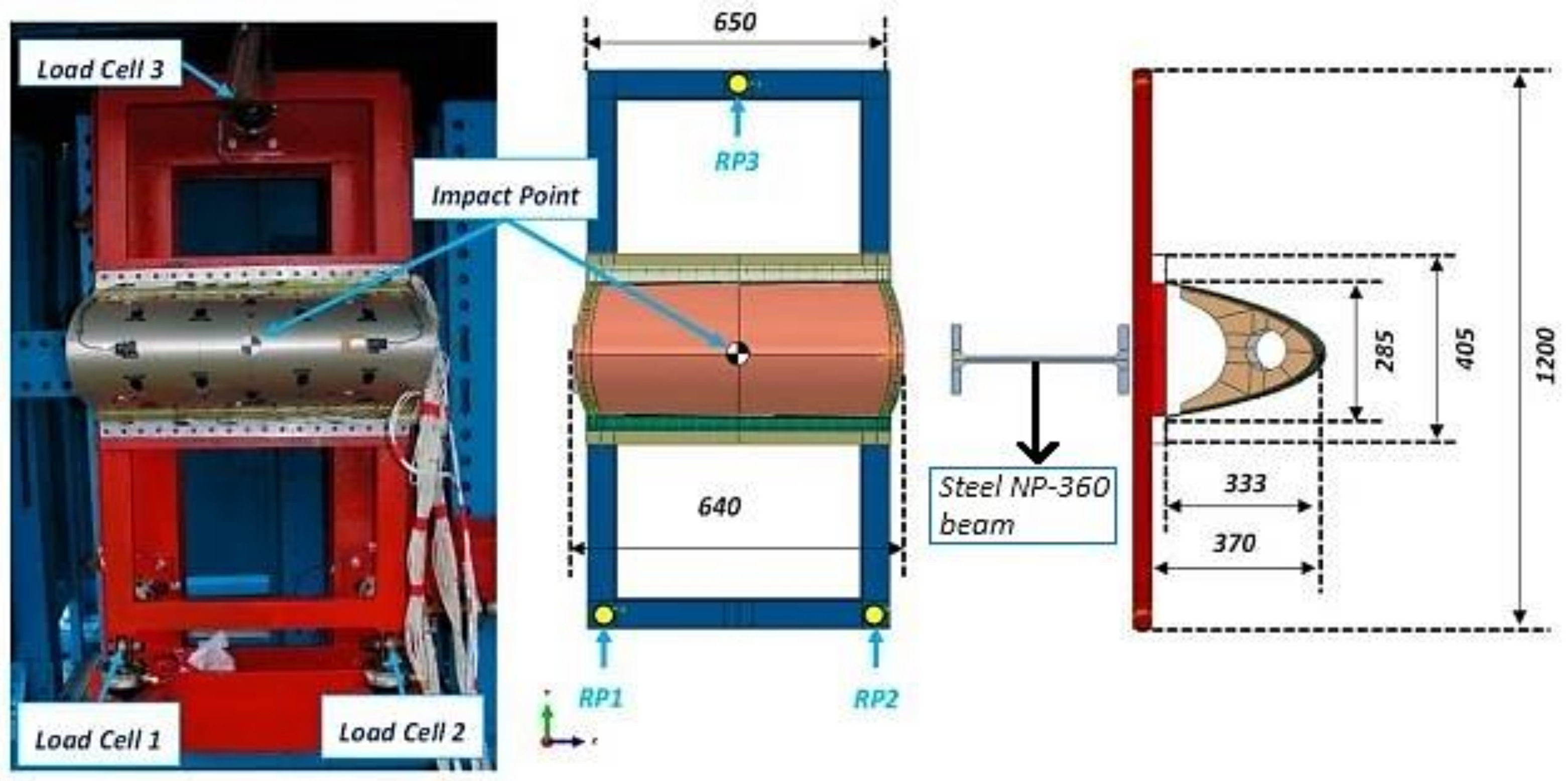
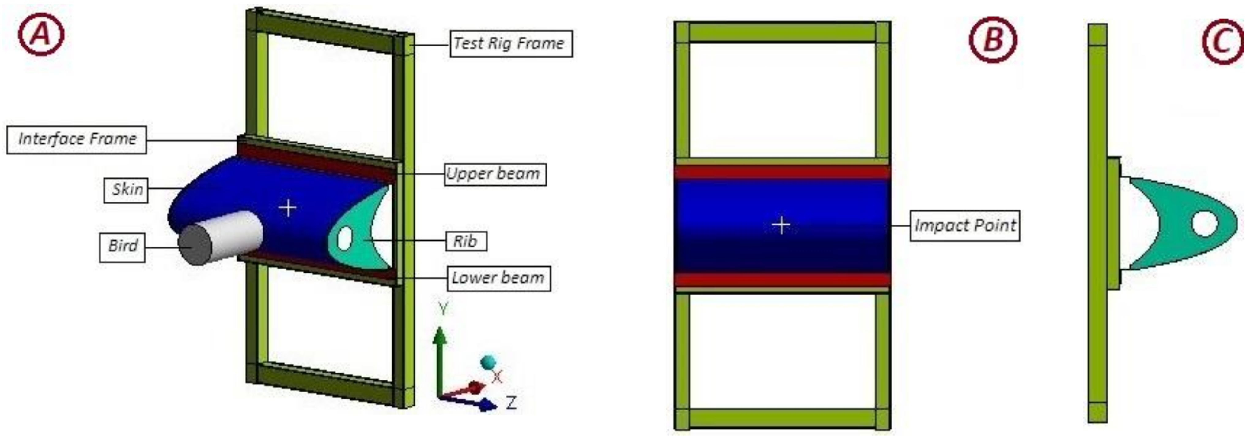
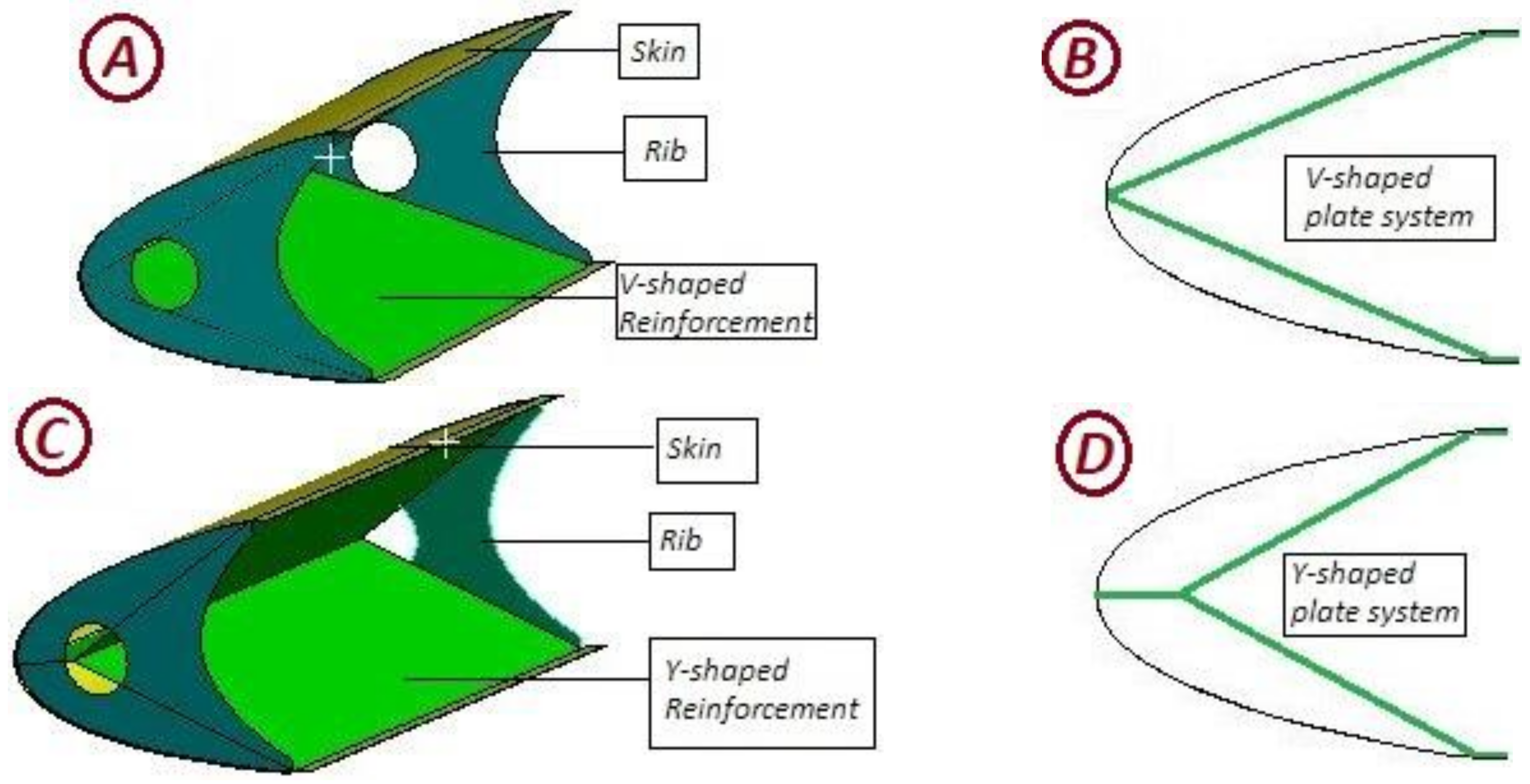
2. Test Article Design

To capture realistic bird impact events, it is important to consider the numerical approaches which should comply with the experimental test articles. Therefore, in this present research, the leading edge along with the test rig is modeled similar to an experimental setup found in the literature [25,34], as shown in Figure 1 and Figure 2, apart from the leading edge materials and thickness of the skin, ribs, and reinforcements, which are discussed in the following section. Additionally, the steel NP-360 beam which is mainly used to prevent the bird impact in case of penetration is not modeled since it has no significance to the numerical outcomes. As for the bird geometry, a cylindrical shape with a diameter of 134 mm and a length of 268 mm is selected to keep the standard length-to-diameter ratio of 2:1 which is also the same as the reference.
Next, the investigated structural reinforcement of the Y-shaped plate system and V-shaped plate system is illustrated in Figure 3. The skin of the leading edge is assumed to be 2.7 mm thick and made of Aluminum-2024-T3 alloy while the ribs are assumed to be 2.1 mm thick made of Aluminum-7075-T6 alloy. The thickness of the Y-shaped and V-shaped plate systems are kept as 2.4 mm made of Aluminum-7075-T6 alloy. Nonetheless, the V-shaped reinforcement weighs 8.7% higher than Y-shaped reinforcement.
For both types of alloys, the Johnson–Cook Material model is selected which suits best when the stress-strain relationship of materials differ significantly at different strain rates. The flow stress is defined as σ = ( A + B ε n ) ( 1 + C ln ε ˙ * ) ( 1 T * m ) , where σ , ε , A denotes as the equivalent stress, equivalent plastic strain, and yield stress of the material, respectively. Other remaining constants, namely, B , n , C and m denote to strain hardening modulus, strain hardening exponent, strain rate constant, and thermal softening exponent (in case of considerable heat generation) [35]. The parameters used in the numerical solver for Aluminum Alloy-2024-T3 and Aluminum Alloy-7075-T6 can be found in Table 1. The upper and lower beam along with the test rigs are assumed to be made of steel 4340 and the properties can be found in Ansys Explicit Library [36].
Finally, the validation of the present numerical model is illustrated in Figure 4 against the experimental and numerical findings of the adopted reference. From the figure, it is evident that the permanent deformation pattern of the skin is similar to the experimental and numerical findings of the reference. Additionally, no penetration is found despite the fact that the distance between the tips of the two ribs after permanent deformation is 161 mm (Figure 4B) while in the reference this value is approximately 293 mm. This discrepancy can be explained based on the materials used for the experimental test article. In the reference, a honeycomb core is adopted which is 6.35 mm high and has an aluminum 2024-T3 made outer and inner face thickness of 1.4 mm and 0.4 mm, respectively. For the present study, the thickness of the skin is simplified to 2.7 mm without any honeycomb core since the main objective of the research is to study the effectiveness of structural reinforcement on the leading edge while in the reference the honeycomb core is used as reinforcement.

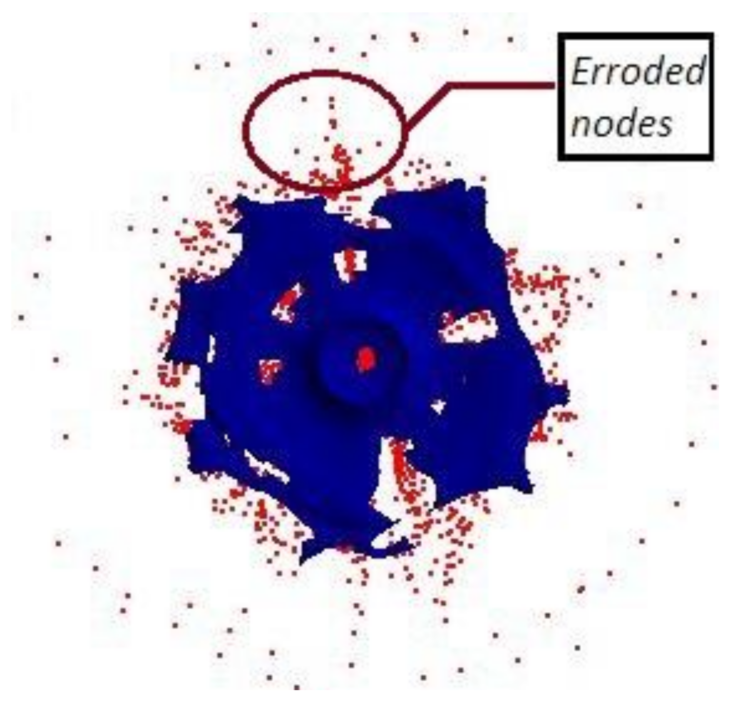
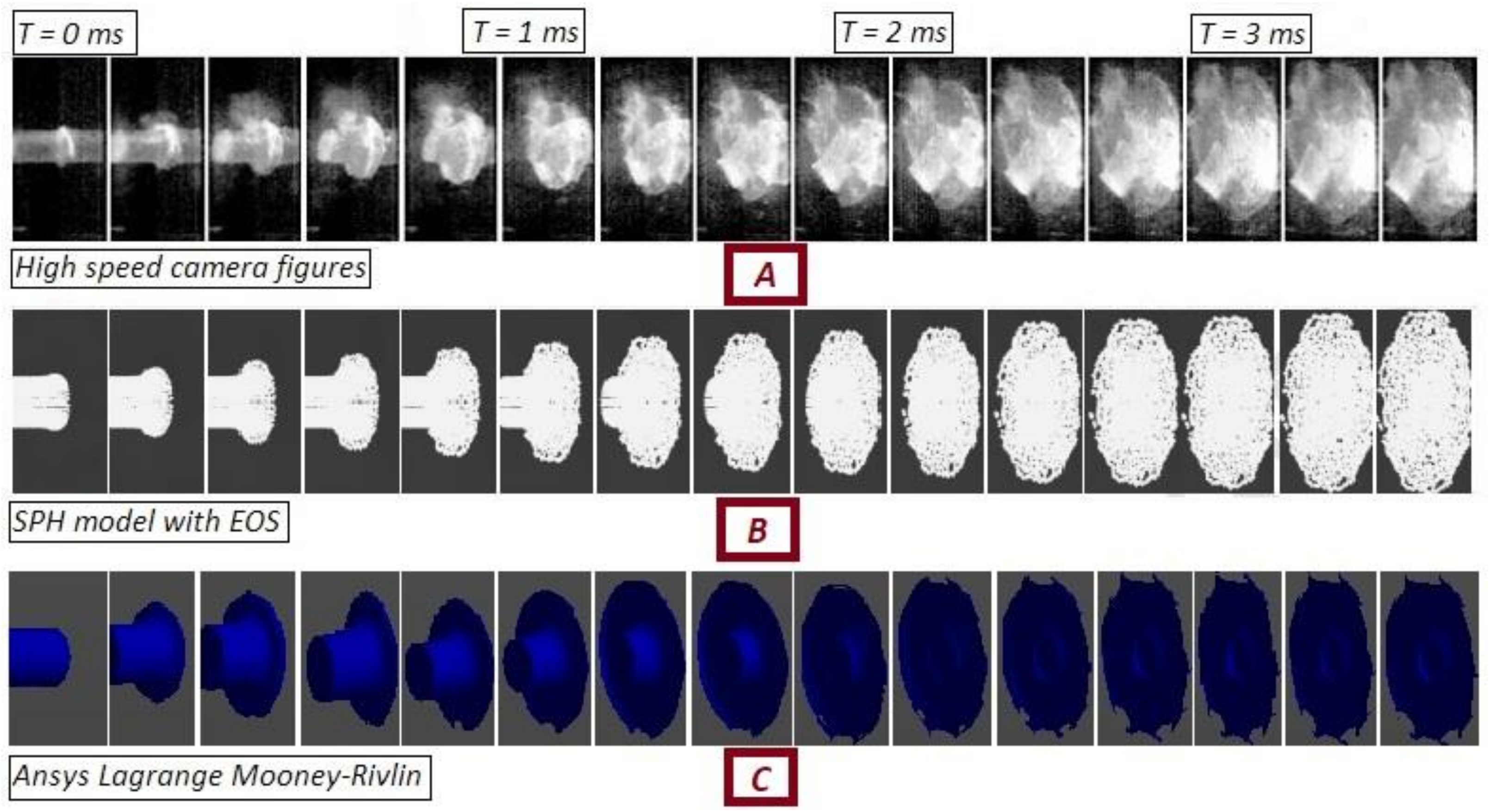
3. Bird Material Model

For the current study, the computational bird model is presented as the Lagrange model with node erosion algorithm, where the highly distorted nodes are removed from the solver after the impact has taken place to stabilize the solution procedure [37], as shown in Figure 5. Moreover, Mooney–Rivlin material parameters are selected, which can be found in Table 2.
Both the Lagrange bird model and material parameters are validated against the experimental data found in the literature [31,38]. In Figure 6A, central back displacement data of an aluminum plate impacted by a ballistic gelatin bird projectile are experimentally measured by the direct image correlation (DIC) method at an impact velocity of 122 m/s, which is compared with the numerical outcomes adopting Ansys. Furthermore, in Figure 6B, the maximum central back displacement values at different impact velocities are correlated. From both the graphs, it is evident that the numerical and experimental data are in excellent agreement.
Finally, the radial spread of the gelatine bird projectile captured by a high-speed camera during experimentation and adopting the SPH method is compared with the current numerical bird model, as shown in Figure 7. An excellent correlation is observed with illustrations found in the literature [38]. In summary, it can be concluded that the Lagrange bird model with node erosion algorithm and Mooney–Rivlin material parameters can be successfully adopted as bird model for the current investigation.

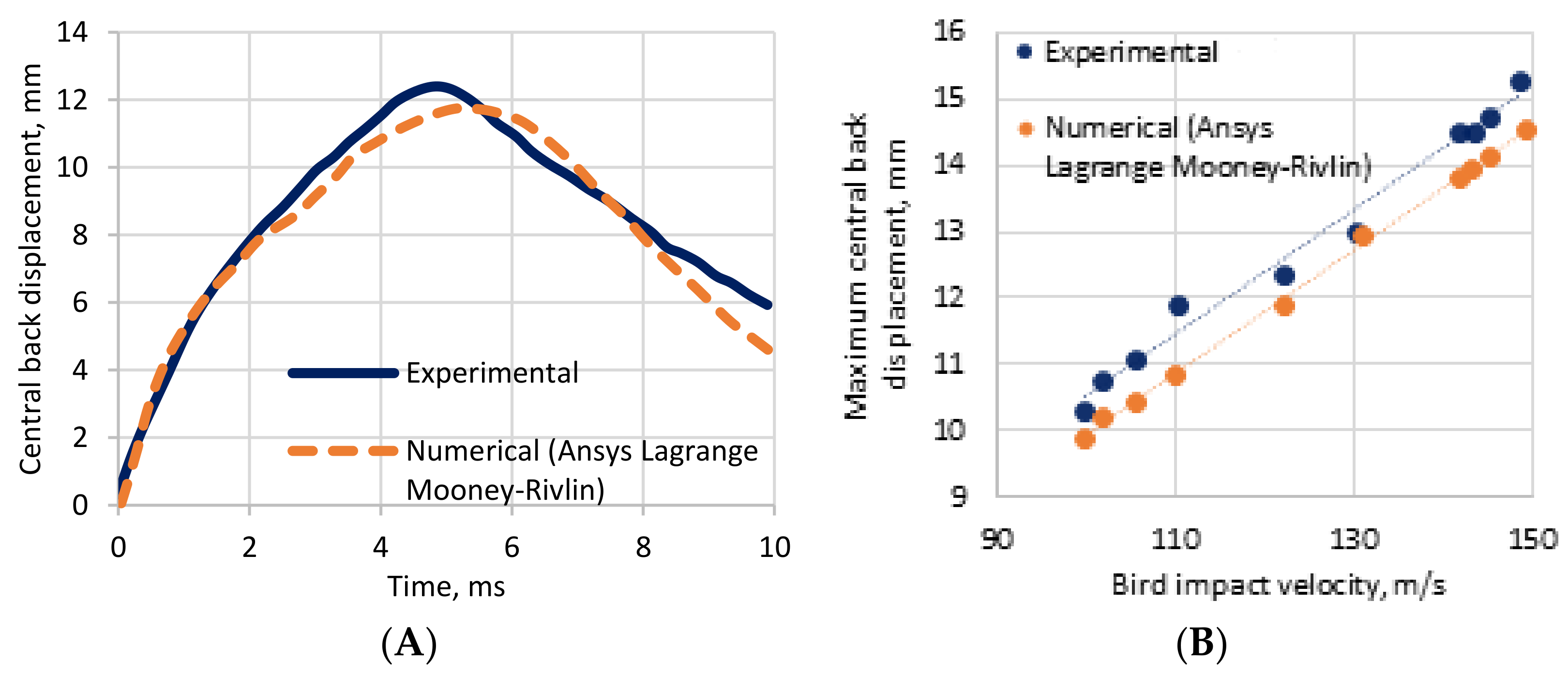
4. Numerical Outcomes

4.1. Bird Strike Impact Events
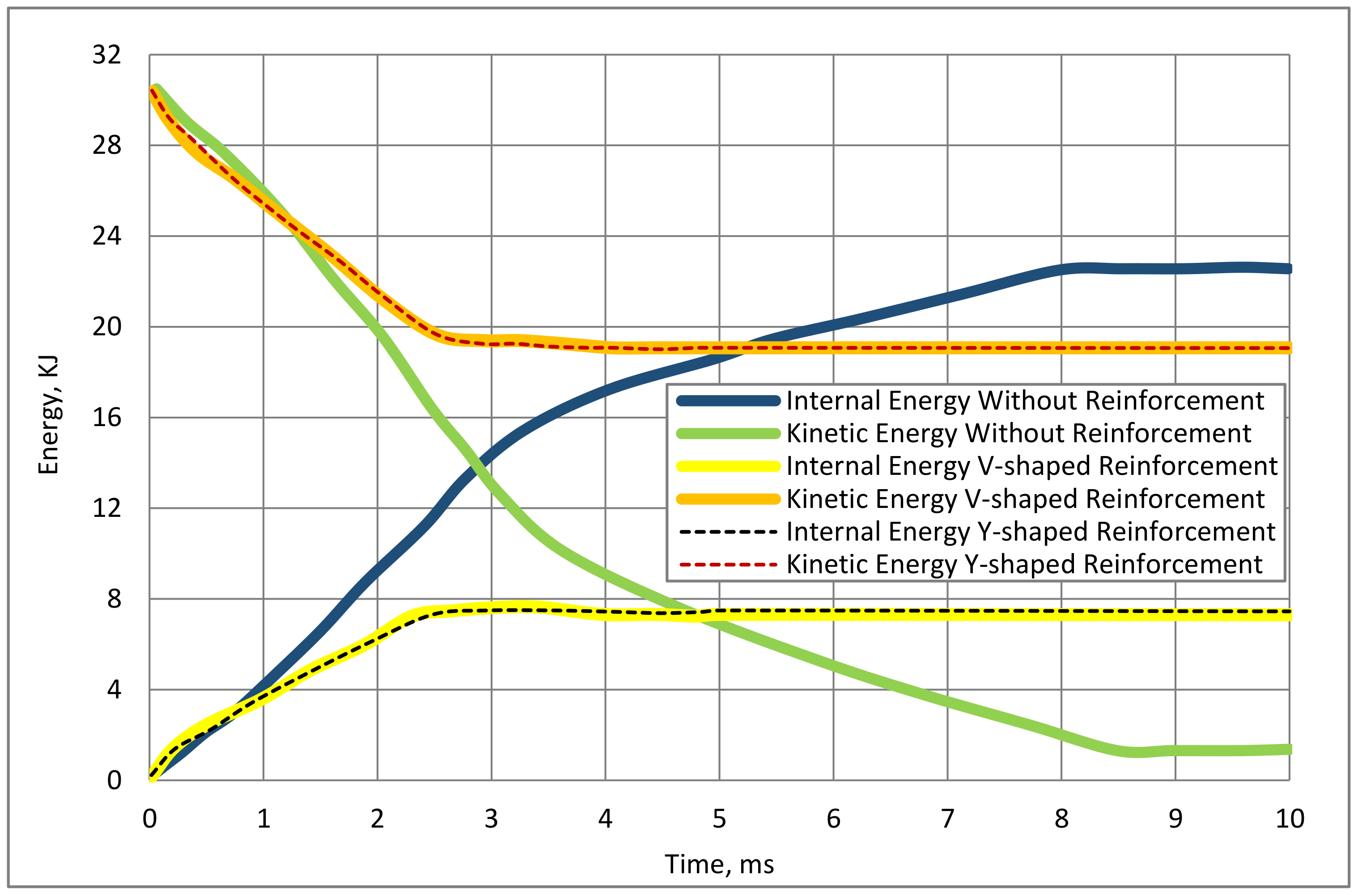
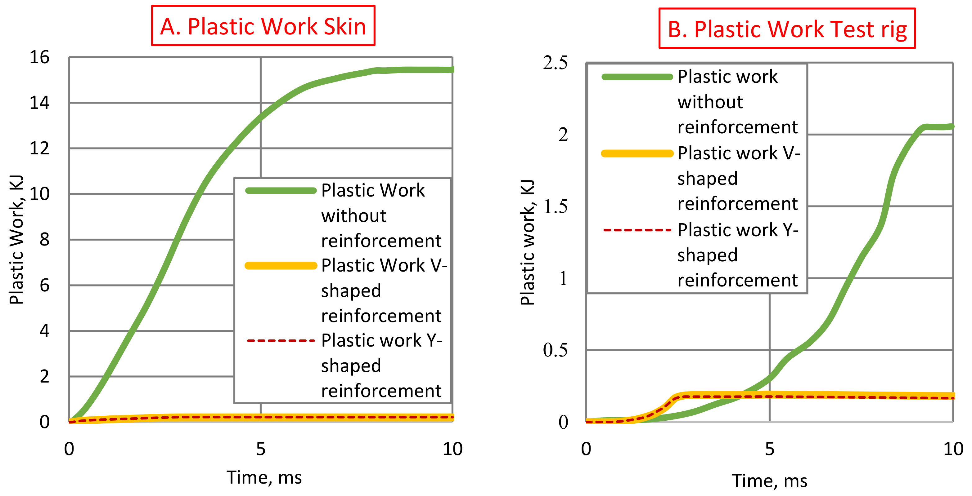
At first, the impact events are discussed from the computational bird model’s point of view, as shown in Figure 8. At the beginning of the impact event, to be precise at 0.5 milliseconds, radial deformation of the bird starts to take place and no visual differences among the leading edge models are observed. However, as time progresses, at 1 millisecond, the bird continues to deform radially for the leading edge without any reinforcement while a tendency of splitting the bird into two pieces is observed for both the V-shaped and Y-shaped reinforcement. Afterwards, at 2 milliseconds, the whole bird model is almost split into half while impacting with reinforced leading edges. In contrast, half of the bird is radially deformed for the case of leading edge without any reinforcement. At 3 milliseconds, the split of the bird is fully completed which is more apparent at 4 milliseconds for reinforcements. Nonetheless, deformation continues to take place for the leading edge having no reinforcement and a fully deformed shape of the bird model can be seen after the termination of the solution, completely crashing on the wing surface. Lastly, it is found that for both the reinforcement types, the bird model impact events are identical.

4.2. Energy Summary

Next, energy conversion data of the whole system comprising both the test rig and leading edge with and without reinforcement can be found in Figure 9. From the illustration, it is evident that most of the kinetic energy of the bird is converged to internal energy for the case of leading edge without any reinforcement. The maximum internal energy reaches the peak value of 22.62 KJ at 8 ms and stabilizes afterward. However, for the case of reinforcements, a completely different scenario can be observed, where the kinetic energy of the bird decreases from 30.4 KJ to 19 KJ and continues to retain the energy. This phenomenon can be described from the previous illustration (Figure 8) where the bird, after being impacted, is sliced into two pieces due to the presence of the reinforcements. Thus, a full crashing of the bird model does not take place and the specified kinetic energy remains in the bird model. Therefore, the system with reinforcements requires the absorption of less kinetic energy, and the maximum peak values of 7.63 KJ and 7.49 KJ internal energy are produced by V-shaped and Y-shaped reinforcements, respectively, which stabilizes at 2.5 milliseconds. Similar to the previous bird strike events, both reinforcement types exhibit almost identical energy summary, generating approximately 67% less internal energy than the system without reinforcement.
Detailed maximum energy dissipation by the components can be seen in Table 3. In all cases, the skin absorbs the highest amount of internal energy. However, the amount of energy dissipation varies largely due to the presence of reinforcements. The skin generates 17 KJ internal energy when no reinforcement is placed, which is approximately 83% higher than the reinforced skins. Furthermore, the test rig also generates a maximum of 3.1 KJ internal energy, which is around 81% higher in contrast to the V-shaped and Y-shaped reinforced leading-edge installed test rigs. It is also interesting to note that, both the reinforcements generate only a small amount of internal energy, which is only 4% of the total internal energy of the system.
Focusing on the plastic work of the skin as illustrated in Figure 10A, it can be seen that the skin without reinforcement experiences a large plastic deformation. The plastic work done by the skin is around 15.44 KJ which is 68.4% of the internal energy of the skin. In contrast, plastic work of the skin with reinforcements is insignificant, to be specific, only 0.21 KJ and suggests a small area of plastic deformation due to the bird strike events. Furthermore, the test rig installed with the leading edge having no reinforcement carries out 2.05 KJ plastic work which can not be neglected considering the contribution to be around 9% of the total internal energy of the system, as shown in Figure 10B. On the other hand, the plastic work of the test rigs with reinforced leading edges is considerably low, only around 0.18 KJ.

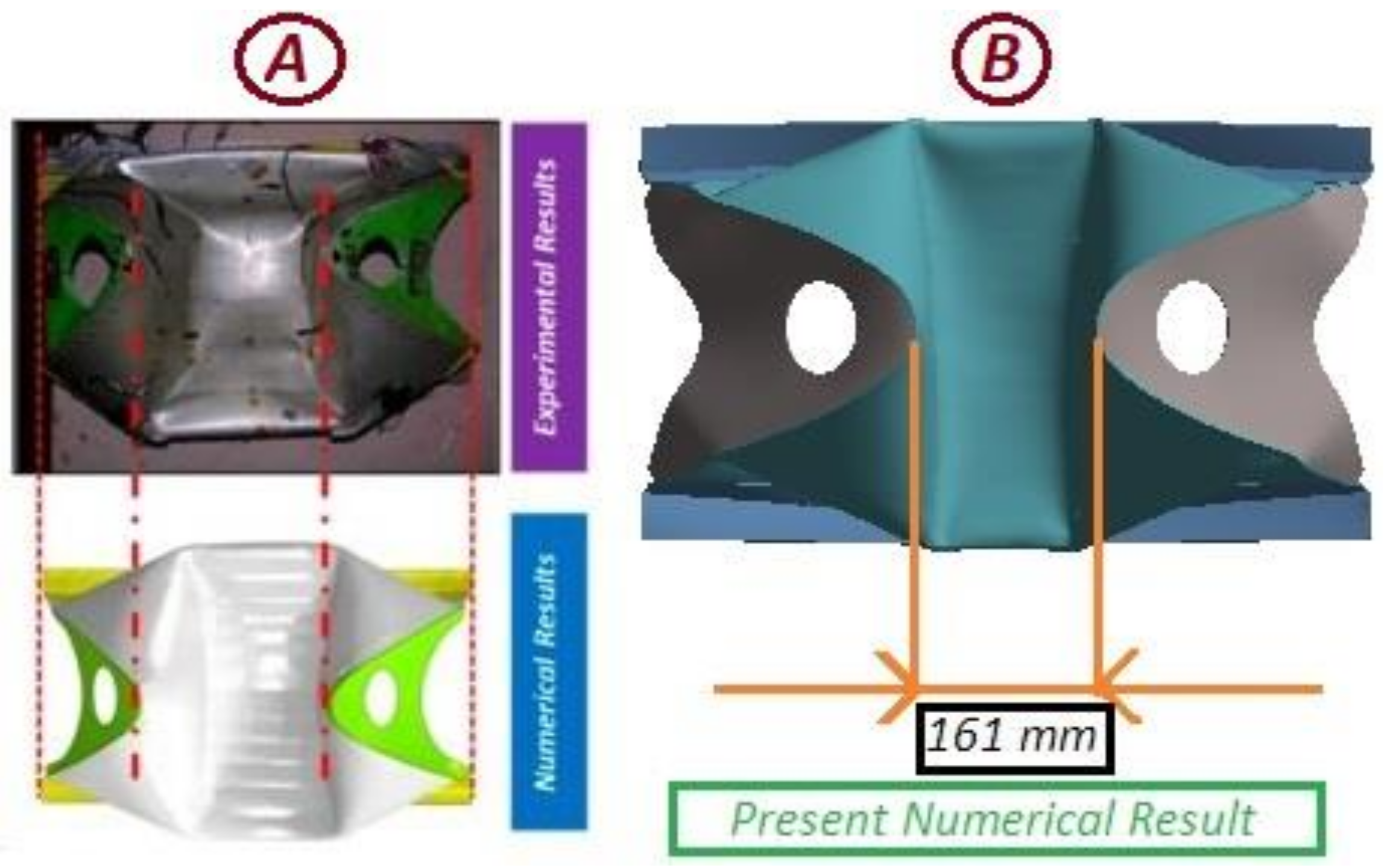
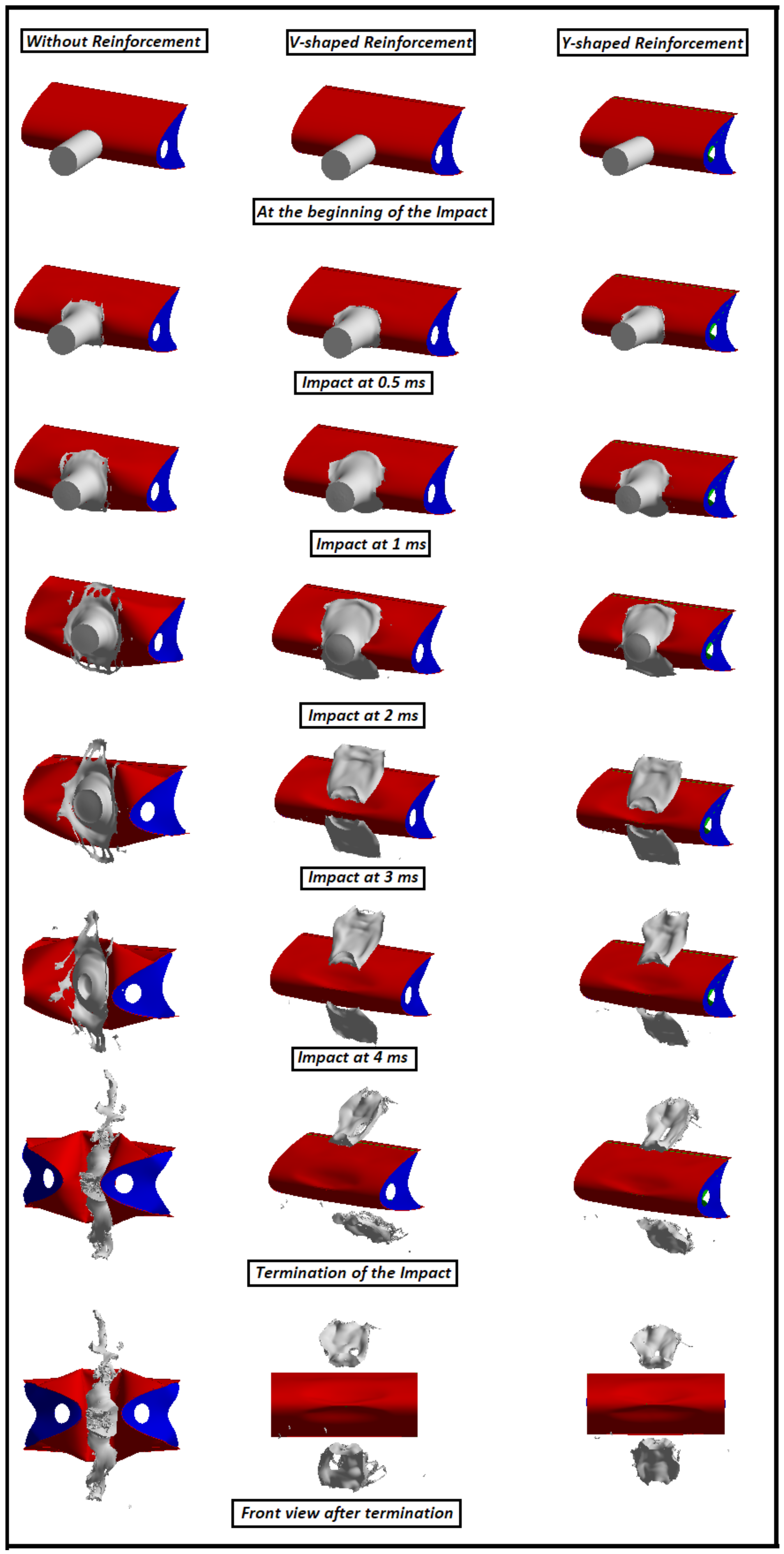
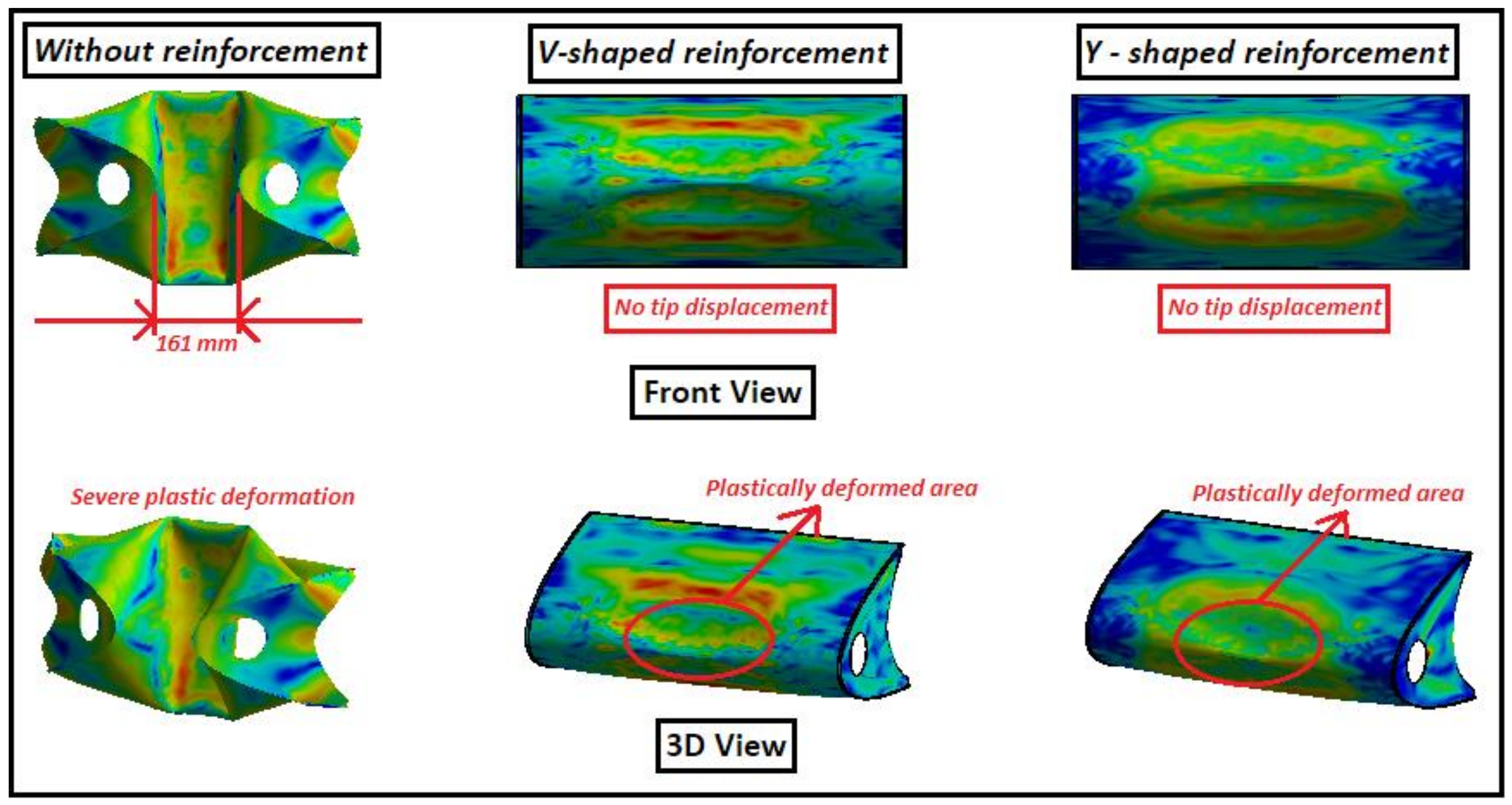
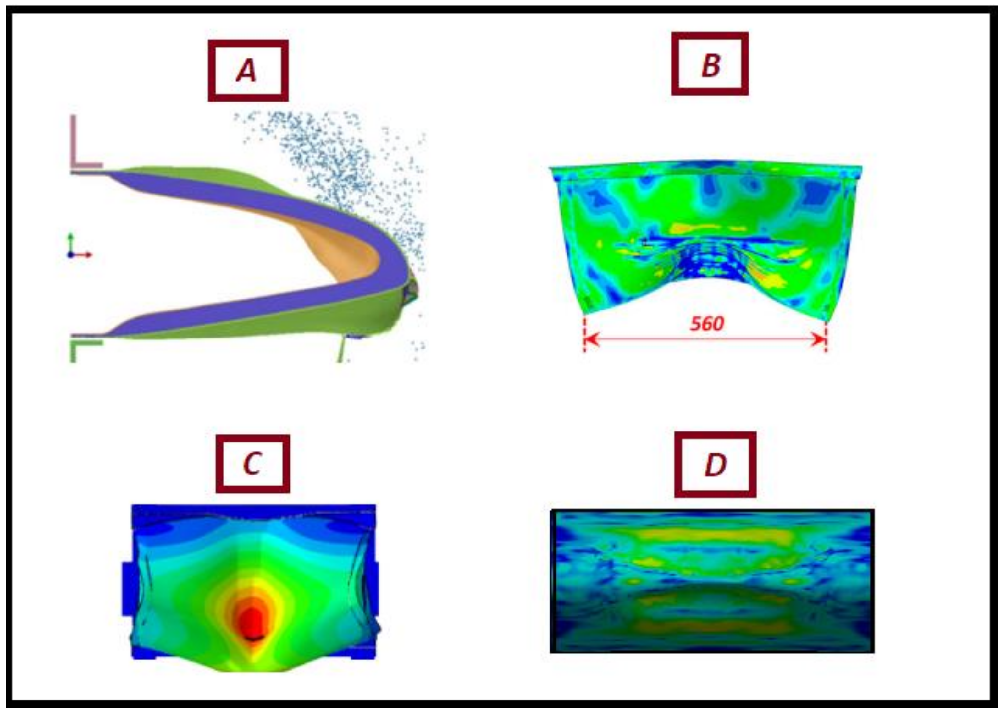
4.3. Deformed Configuration

Finally, the permanent deformation of the wing leading edge after the bird impact events can be seen in Figure 11. Even though no penetration takes place, large plastic deformation is found for the wing leading edge without reinforcement. The displacement between the two rib tips is measured as 161 mm, which was initially 640 mm before the impact. On the other hand, despite some plastic deformation near the impacted area having been identified, no tip displacement is observed for the leading edge with reinforcements. This confirms that the leading edge will retain its aerodynamic shape after the bird strike, eventually providing a safer flight.
In terms of plastic displacement and tip displacement, a comparison is also made with other available reinforcement types found in the literature [24,25,34], as shown in Figure 12. From the illustration, it is apparent that despite being reinforced, all other leading edges have a significant plastic deformation and only provide protection for not being penetrated fully due to the impact, complying with the FAR 25.631 regulations. However, the Y-shaped and V-shaped reinforced leading edges not only satisfy the regulations but also ensure a better aerodynamically shaped structure. It is also noteworthy that other reinforcements cannot split the bird into two pieces and have to absorb all the kinetic energy of the bird until it completely gets demolished.

5. Conclusions

The present work evaluates the crashworthiness performance of two different reinforcements installed in a metallic aircraft wing leading edge under bird strike events and compared with a traditional leading edge having no reinforcement placed on it. Numerical setup and outcomes have been validated against the experimental data adopting both qualitative and quantitative techniques. From the results, it is found that reinforcements aid in splitting the impacted birds into two pieces. Therefore, the leading edge is required to absorb much less kinetic energy, generating 81.53% less internal energy than the leading edge without reinforcement. Among the components, the skin dissipates the maximum amount of energy followed by the test rig. The plastic work done by the skin is 15.4 KJ without reinforcement which is 0.21 KJ for reinforcement variants.
Another important outcome of the study is that the leading edge with reinforcements does not deform drastically. A tip displacement of 73.9% is observed without reinforcement, suggesting a potential aerodynamic shape loss of the structure. Additionally, other reinforcement types found in the literature have tip displacements after being impacted while the leading edge with reinforcement system withstands the bird impact without disturbing the tip location.
It is also interesting to see that both the reinforcement types have similar crashworthiness performance. Even though no weight comparison against internal energy is studied, from the total mass a significant difference of 8.7% is obtained which directs to a comparison study of the reinforcements with further optimized design.
Finally, based on the observations of the crashworthiness factors, it is suggested to adopt the structural reinforcement as the primary choice of reinforcement to the leading edge wing structure to withstand the high velocity shock impacts effectively.

Author Contributions

Conceptualization, M.A.A. and S.B.R.; methodology, M.A.A.; software, S.B.R.; formal analysis, M.A.A.; investigation, S.B.R.; data curation, M.A.A.; writing—original draft preparation, M.A.A.; writing—review and editing, S.B.R. and K.Z.; supervision, K.Z. All authors have read and agreed to the published version of the manuscript.

Funding

This research received no external funding.

Institutional Review Board Statement

Not applicable.

Informed Consent Statement

Not applicable.

Data Availability Statement

All data can be obtained by communicating with the authors.

Acknowledgments

All the authors greatly acknowledge the support of the Chinese Government Scholarship Grant (CSC) to support Ph.D. education in China. The authors would also like to thank the three anonymous reviewers for their critical reviews which have improved the quality of the manuscript greatly.

Conflicts of Interest

The authors declare no conflict of interest.

References

  1. FAA Foreign Object Debris Program. Available online: https://www.faa.gov/airports/airport_safety/fod/ (accessed on 3 March 2022).
  2. Mao, R.; Meguid, S.; Ng, T. Transient three dimensional finite element analysis of a bird striking a fan blade. Int. J. Mech. Mater. Design 2008, 4, 79–96. [Google Scholar] [CrossRef] [Green Version]
  3. Plassard, F.; Hereil, P.; Joseph, P.; Mespoulet, J. Experimental and numerical study of a bird strike against a windshield. EPJ Web Conf. 2015, 94, 01051. [Google Scholar] [CrossRef] [Green Version]
  4. Wilbeck, J.S.; Barber, J.P. Bird impact loading. Shock Vib. Bull. 1978, 48, 115–122. [Google Scholar]
  5. Impact Behavior of Low Strength Projectiles. Available online: https://apps.dtic.mil/sti/citations/ADA060423 (accessed on 3 March 2022).
  6. Guida, M.; Marulo, F.; Meo, M.; Riccio, M. Analysis of Bird Impact on a Composite Tailplane Leading Edge. Appl. Compos. Mater. 2008, 15, 241–257. [Google Scholar] [CrossRef] [Green Version]
  7. Guida, M.; Marulo, F.; Polito, T.; Meo, M.; Riccio, M. Design and Testing of a Fiber-Metal-Laminate Bird-Strike-Resistant Leading Edge. J. Aircr. 2009, 46, 2121–2129. [Google Scholar] [CrossRef] [Green Version]
  8. Guida, M.; Marulo, F.; Meo, M.; Russo, S. Experimental Tests Analysis of Fiber Metal Laminate under Birdstrike. Mech. Adv. Mater. Struct. 2012, 19, 376–395. [Google Scholar] [CrossRef] [Green Version]
  9. Georgiadis, S.; Gunnion, A.; Thomson, R.; Cartwright, B. Bird-strike simulation for certification of the Boeing 787 composite moveable trailing edge. Compos. Struct. 2008, 86, 258–268. [Google Scholar]
  10. Orlando, S.; Marulo, F.; Guida, M.; Timbrato, F. Bird strike assessment for a composite wing flap. Int. J. Crashworthiness 2017, 23, 219–235. [Google Scholar] [CrossRef]
  11. Liu, J.; Li, Y.; Gao, X. Bird strike on a flat plate: Experiments and numerical simulations. Int. J. Impact Eng. 2014, 70, 21–37. [Google Scholar] [CrossRef]
  12. Grimaldi, A.; Sollo, A.; Guida, M.; Marulo, F. Parametric study of a SPH high velocity impact analysis—A birdstrike windshield application. Compos. Struct. 2013, 96, 616–630. [Google Scholar] [CrossRef]
  13. Zhang, Z.; Li, L.; Zhang, D. Effect of arbitrary yaw/pitch angle in bird strike numerical simulation using SPH method. Aerosp. Sci. Technol. 2018, 81, 284–293. [Google Scholar] [CrossRef]
  14. Badshah, S.; Naeem, A.; Farhan Rafique, A.; Ul Haq, I.; Abdullah Malik, S. Numerical Study on the Critical Frequency Response of Jet Engine Rotors for Blade-Off Conditions against Bird Strike. Appl. Sci. 2019, 9, 5568. [Google Scholar] [CrossRef] [Green Version]
  15. Wu, B.; Lin, J.; Hedayati, R.; Zhang, G.; Zhang, J.; Zhang, L. Dynamic Responses of the Aero-Engine Rotor System to Bird Strike on Fan Blades at Different Rotational Speeds. Appl. Sci. 2021, 11, 8883. [Google Scholar] [CrossRef]
  16. Zhou, Y.; Sun, Y.; Huang, T. SPH-FEM Design of Laminated Plies under Bird-Strike Impact. Aerospace 2019, 6, 112. [Google Scholar] [CrossRef] [Green Version]
  17. Zhou, Y.; Sun, Y.; Huang, T. Bird-Strike Resistance of Composite Laminates with Different Materials. Materials 2019, 13, 129. [Google Scholar] [CrossRef] [Green Version]
  18. Kreculj, D.; Rasuo, B. Impact damage modeling in laminated composite aircraft structures. In Sustainable Composites for Aerospace Applications; Woodhead Publishing: Cambridge, UK, 2018; pp. 125–153. [Google Scholar]
  19. Kreculj, D.; Rasuo, B. Review of Impact Damages Modelling in Laminated Composite Aircraft Structures, 1st ed.; Tehnicki Vjesnik; University of Osijek: Osijek, Croatia, 2013. [Google Scholar]
  20. Hasan, M. Interface Failure of Heated GLARETM Fiber–Metal Laminates under Bird Strike. Aerospace 2020, 7, 28. [Google Scholar] [CrossRef] [Green Version]
  21. Reglero, J.; Rodríguez-Pérez, M.; Solórzano, E.; de Saja, J. Aluminium foams as a filler for leading edges: Improvements in the mechanical behaviour under bird strike impact tests. Mater. Design 2011, 32, 907–910. [Google Scholar] [CrossRef]
  22. Liu, J.; Li, Y.; Yu, X.; Tang, Z.; Gao, X.; Lv, J.; Zhang, Z. A novel design for reinforcing the aircraft tail leading edge structure against bird strike. Int. J. Impact Eng. 2017, 105, 89–101. [Google Scholar] [CrossRef]
  23. Qiu, J.; Wang, D.; Liu, C.; Chen, L.; Huang, H.; Sun, Q. Dynamic response of bird strike on honeycomb-based sandwich panels of composite leading edge. Int. J. Crashworthiness 2020, 26, 424–437. [Google Scholar] [CrossRef]
  24. Yu, Z.; Xue, P.; Yao, P.; Zahran, M. Novel Design of Wing Leading Edge against Birdstrike. J. Aerosp. Eng. 2020, 33, 04020009. [Google Scholar] [CrossRef]
  25. Di Caprio, F.; Sellitto, A.; Saputo, S.; Guida, M.; Riccio, A. A Sensitivity Analysis of the Damage Behavior of a Leading-Edge Subject to Bird Strike. Appl. Sci. 2020, 10, 8187. [Google Scholar] [CrossRef]
  26. Slimane, S.; Slimane, A.; Guelailia, A.; Boudjemai, A.; Kebdani, S.; Smahat, A.; Mouloud, D. Hypervelocity impact on honeycomb structure reinforced with bi-layer ceramic/aluminum facesheets used for spacecraft shielding. Mech. Adv. Mater. Struct. 2021, 1–19. [Google Scholar] [CrossRef]
  27. Meguid, S.; Mao, R.; Ng, T. FE analysis of geometry effects of an artificial bird striking an aeroengine fan blade. Int. J. Impact Eng. 2008, 35, 487–498. [Google Scholar] [CrossRef]
  28. Heimbs, S. Computational methods for bird strike simulations: A review. Comput. Struct. 2011, 89, 2093–2112. [Google Scholar] [CrossRef]
  29. Hedayati, R.; Sadighi, M. Bird Strike: An Experimental, Numerical and Theoretical Investigation, 1st ed.; Woodhead Publishing: Cambridge, UK; pp. 113–135.
  30. Hedayati, R.; Jahanbakhshi, M. Finite element analysis of an aluminum airplane stabilizer against birdstrike. J. Braz. Soc. Mech. Sci. Eng. 2015, 38, 317–326. [Google Scholar] [CrossRef]
  31. Zhou, J. Experimental and Numerical Investigation of Soft Impact Loading on Aircraft Materials. Ph.D. Thesis, Imperial College, London, UK, 2018. [Google Scholar]
  32. Hedayati, R.; Ziaei-Rad, S. Effect of Impact Orientation on Bird Strike Analysis. Int. J. Veh. Struct. Syst. 2011, 3, 184–191. [Google Scholar] [CrossRef]
  33. McCallum, S.; Shoji, H.; Akiyama, H. Development of an advanced multi-material bird-strike model using the smoothed particle hydrodynamics method. Int. J. Crashworthiness 2013, 18, 579–597. [Google Scholar] [CrossRef]
  34. Di Caprio, F.; Cristillo, D.; Saputo, S.; Guida, M.; Riccio, A. Crashworthiness of wing leading edges under bird impact event. Compos. Struct. 2019, 216, 39–52. [Google Scholar] [CrossRef]
  35. Azeem Aslam, M.; Ke, Z.; Rayhan, S.; Faizan, M.; Mamuda Bello, I. An investigation of soft impacts on selected aerospace grade alloys based on Johnson-Cook Material Model. J. Phys. Conf. Ser. 2020, 1707, 012008. [Google Scholar] [CrossRef]
  36. Ansys Explicit Library; Ansys: Canonsburg, PA, USA, 2021.
  37. Aslam, M.; Rayhan, S.; Ke, Z.; Yu, W. Ballistic gelatin Lagrange Mooney-Rivlin material model as a substitute of bird in finite element bird strike case studies. Lat. Am. J. Solids Struct. 2020, 17, 1–15. [Google Scholar] [CrossRef]
  38. Zhou, J.; Liu, J.; Zhang, X.; Yan, Y.; Jiang, L.; Mohagheghian, I.; Dear, J.; Charalambides, M. Experimental and numerical investigation of high velocity soft impact loading on aircraft materials. Aerosp. Sci. Technol. 2019, 90, 44–58. [Google Scholar] [CrossRef]
Figure 1. Experimental and Numerical Model according to the literature. Reprinted with permission from Refs. [25,34]. 2020 [25] and 2019 [34], Di Caprio et al.
Aerospace 09 00260 g001
Figure 2. Present Numerical Setup. (A) 3D view with sub-components; (B) Frontal view; (C) Side view.
Aerospace 09 00260 g002
Figure 3. Structurally reinforced anti-bird-strike system. (A) V-shaped reinforcement; (B) Side view of V-shaped reinforcement; (C) Y-shaped reinforcement; (D) Side view of Y-shaped reinforcement.
Aerospace 09 00260 g003
Figure 4. Post impact permanent deformation. (A) Experimental and numerical results from the reference. Reprinted with permission from Refs. [25,34]. 2020 [25] and 2019 [34], Di Caprio et al.; (B) Present numerical result.
Aerospace 09 00260 g004
Figure 5. Eroded nodes after an impact.
Aerospace 09 00260 g005
Figure 6. Post impact displacement data of experimental [38] and numerical outcomes. (A) Central back displacement at 122 m/s; (B) Maximum central back displacement at different impact velocities.
Aerospace 09 00260 g006
Figure 7. Radial spread of bird model. (A) Experimental observation. Reprinted with permission from Ref. [38]. 2019, Zhou et al.; (B) SPH model. Reprinted with permission from Ref. [38]. 2019, Zhou et al.; (C) Current Lagrange model.
Aerospace 09 00260 g007
Figure 8. Bird projectile impact events.
Aerospace 09 00260 g008
Figure 9. Energy conversion data during bird strikes.
Aerospace 09 00260 g009
Figure 10. Plastic work. (A) Skin; (B) Test Rig.
Aerospace 09 00260 g010
Figure 11. Permanent deformation of the wing leading edges.
Aerospace 09 00260 g011
Figure 12. Comparison of permanent deformation of the wing leading edges with the literature references. (A) Best configured leading edge. Reprinted with permission from Ref. [24]. 2020, Yu. et al.; (B) Best configured leading edge. Reprinted with permission from Ref. [25]. 2020, Di Caprio et al.; (C) Best configured leading edge. Reprinted with permission from Ref. [34]. 2019, Di Caprio et al.; (D) Present Y-shaped and V-shaped configuration.
Aerospace 09 00260 g012
Table 1. Johnson–Cook material parameters of Aluminum alloys [35].
ParametersAluminum-2024-T3Aluminum-7075-T6
Density, ρ (kg m−3)27002700
Poisson’s ratio, υ0.30.3
Young’s modulus, E (GPa)7070
Yield stress, A (MPa)352520
Strain hardening modulus, B (MPa)440477
Strain hardening exponent, n0.420.52
Reference strain rate, ε0 (s−1)3.3 × 10−45 × 10−4
Strain rate coefficient, C0.00830.001
Thermal softening exponent, m1.71
Reference temperature, T0 (°K)293293
Melting temperature, Tmelt (°K)775893
Specific heat (J/kg-°K)900910
Table 2. Bird Material Parameters [31].
Density, ρ (kg m−3)Material Constant, C0 (MPa)Material Constant, C10 (MPa)
9680.2180.0805
Table 3. Maximum internal energy by the components.
Wing ModelSkin, KJRibs, KJReinforcement, KJTest Rig, KJ
No reinforcement170.33-3.1
V-shaped reinforcement2.80.060.3240.61
Y-shaped reinforcement2.930.060.30.55
Publisher’s Note: MDPI stays neutral with regard to jurisdictional claims in published maps and institutional affiliations.

