
A Polymorphing Wing Capable of Span Extension and Variable Pitch


 and
and
Abstract
:1. Introduction
1.1. Span Morphing Literature
1.2. Twist/Pitch Morphing Literature
2. The Polymorphing Concept
2.1. The ASAPP Wing
2.2. Modes of Operation
3. Aerodynamic Analysis
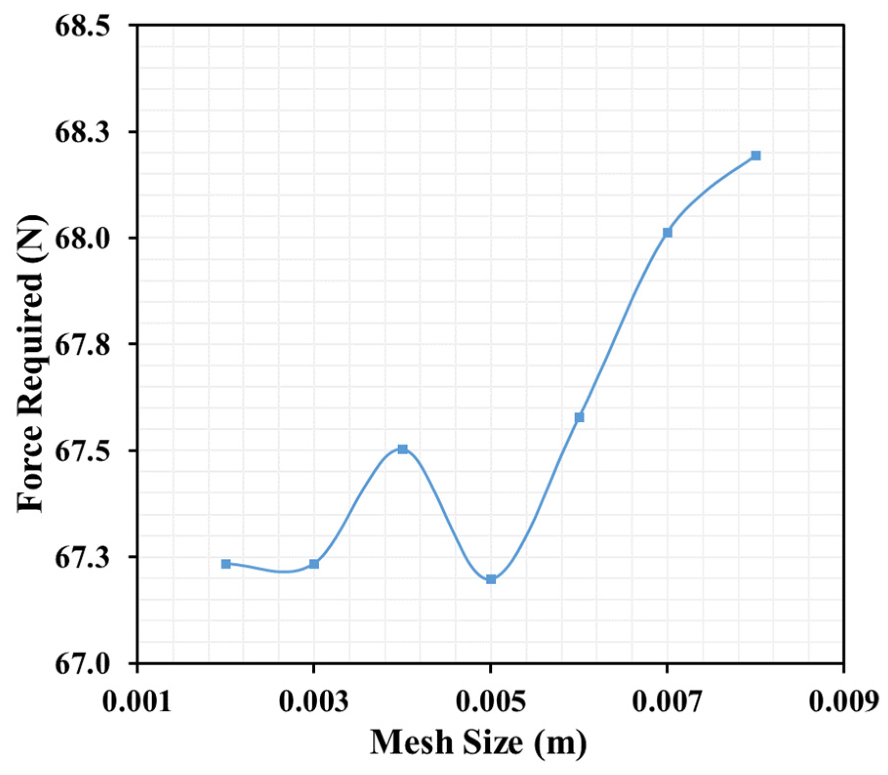
3.1. Aerodynamic Mesh Convergence
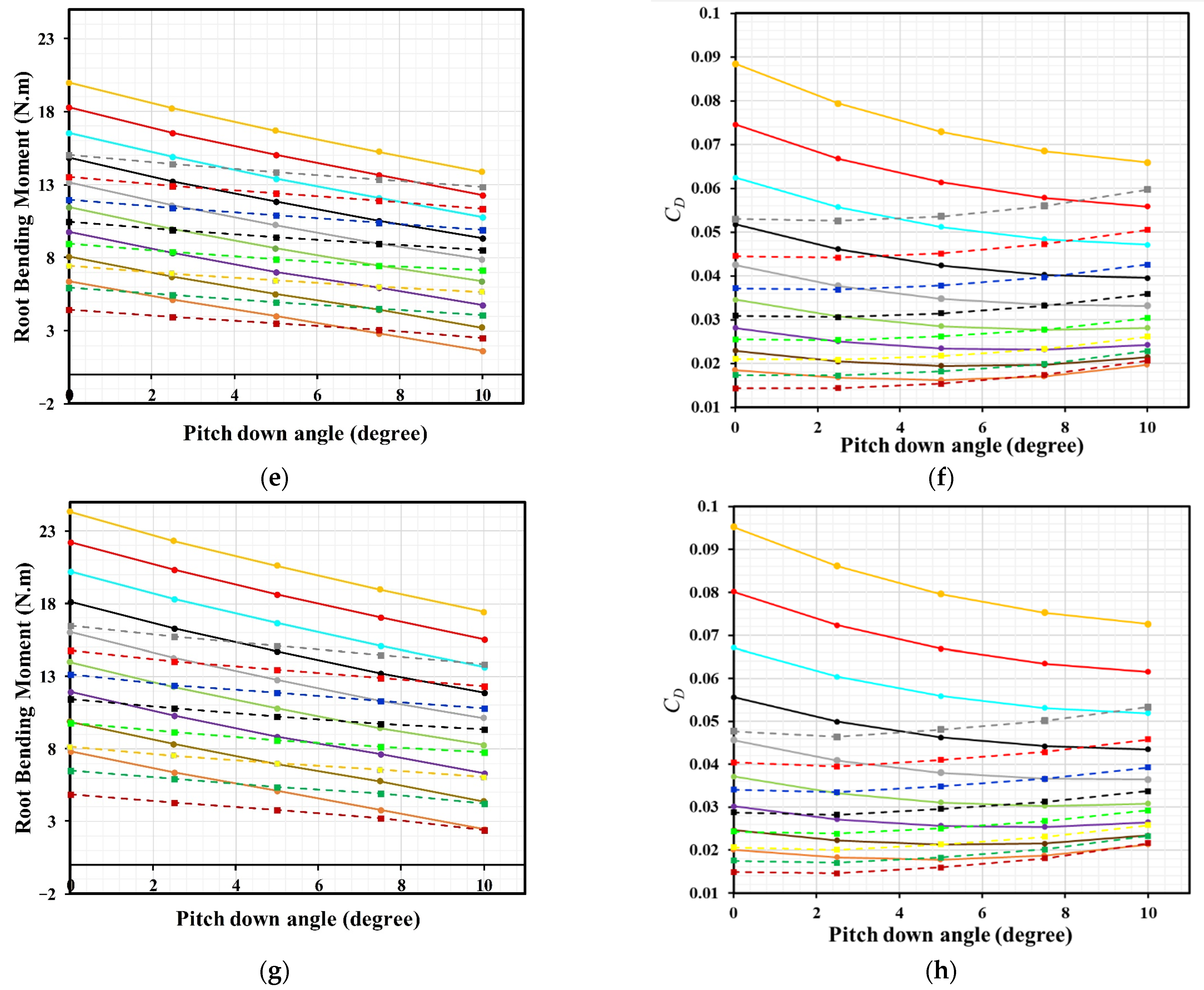
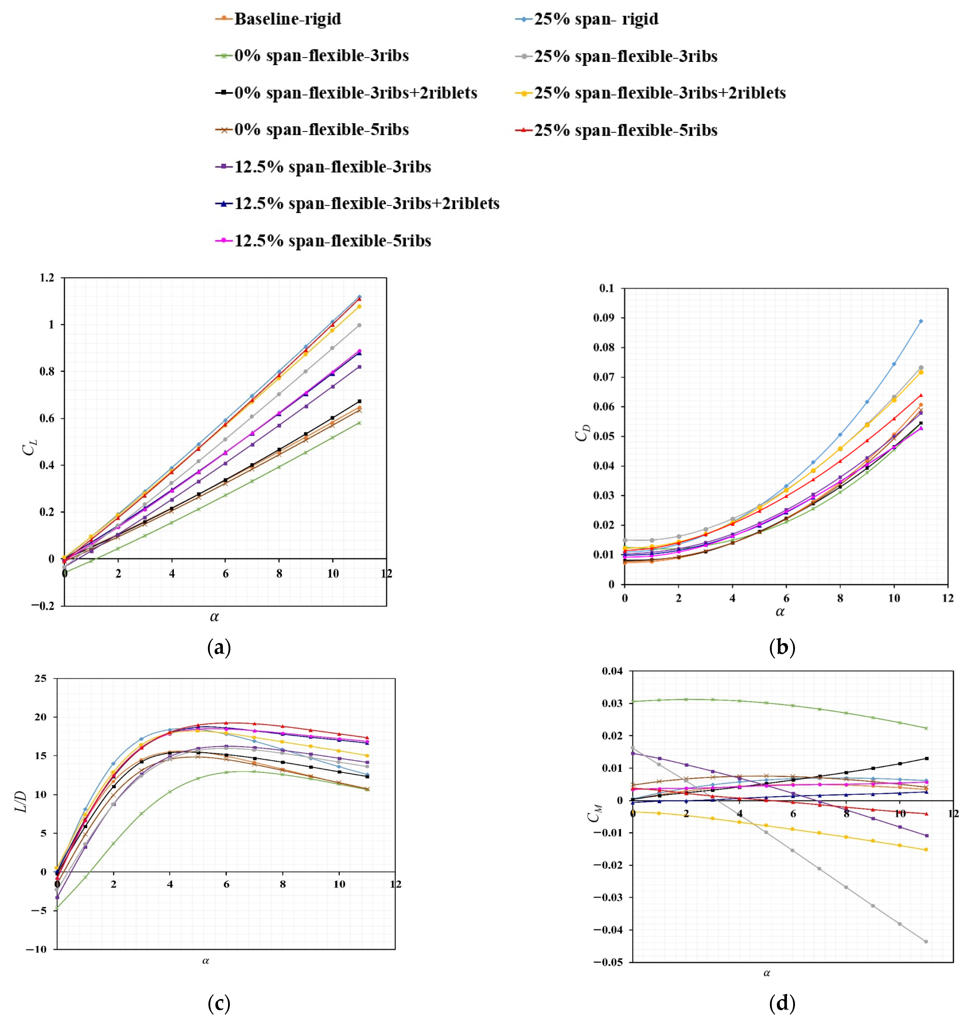
3.2. Aerodynamic Results
4. Structural Design and Sizing
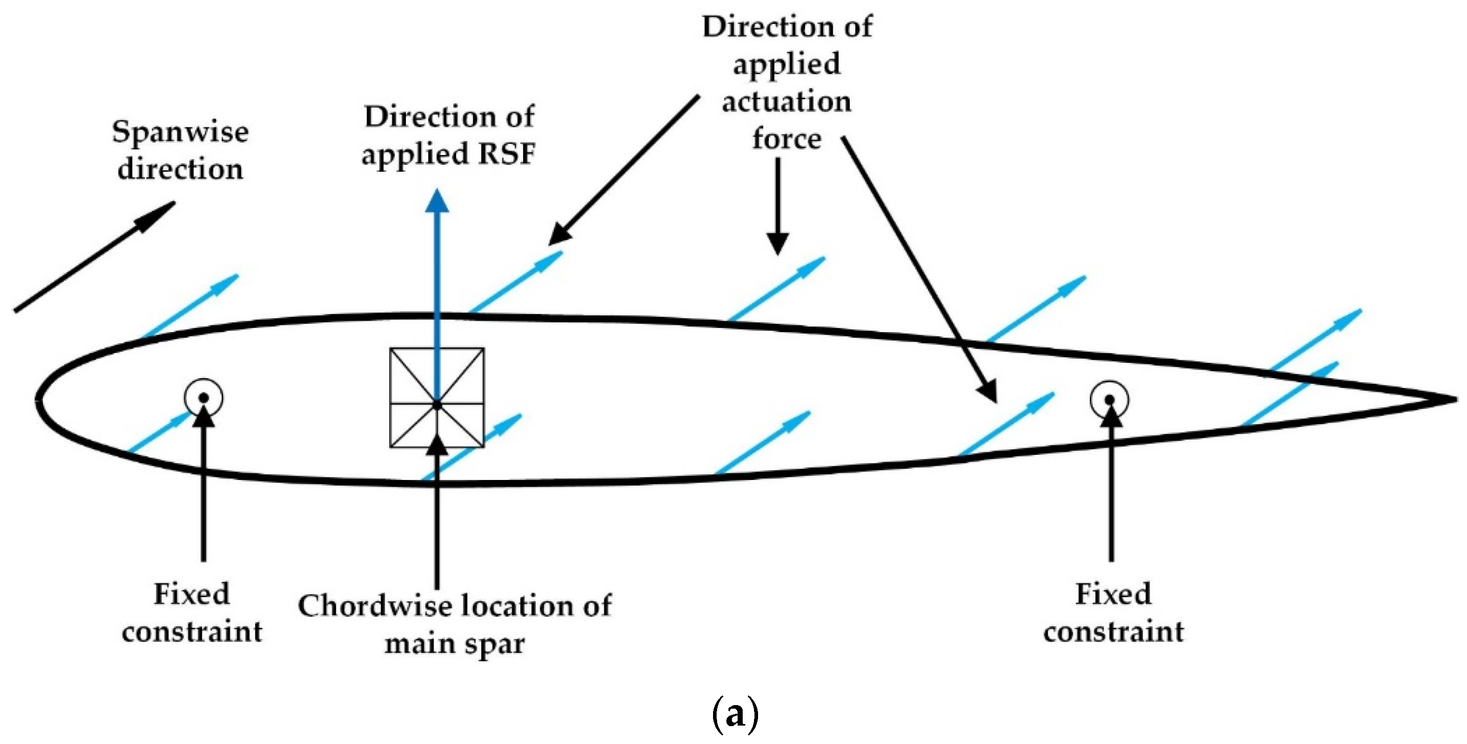
4.1. Torsional Spring
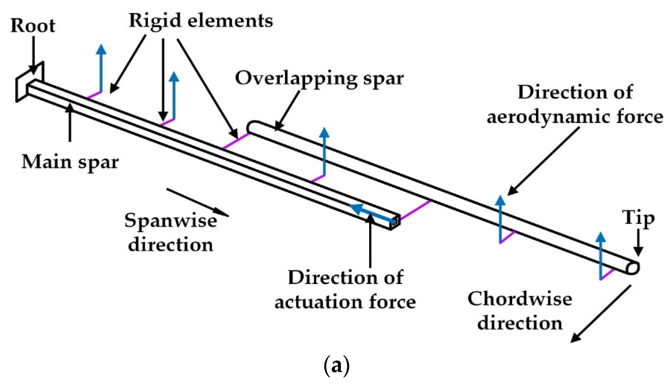
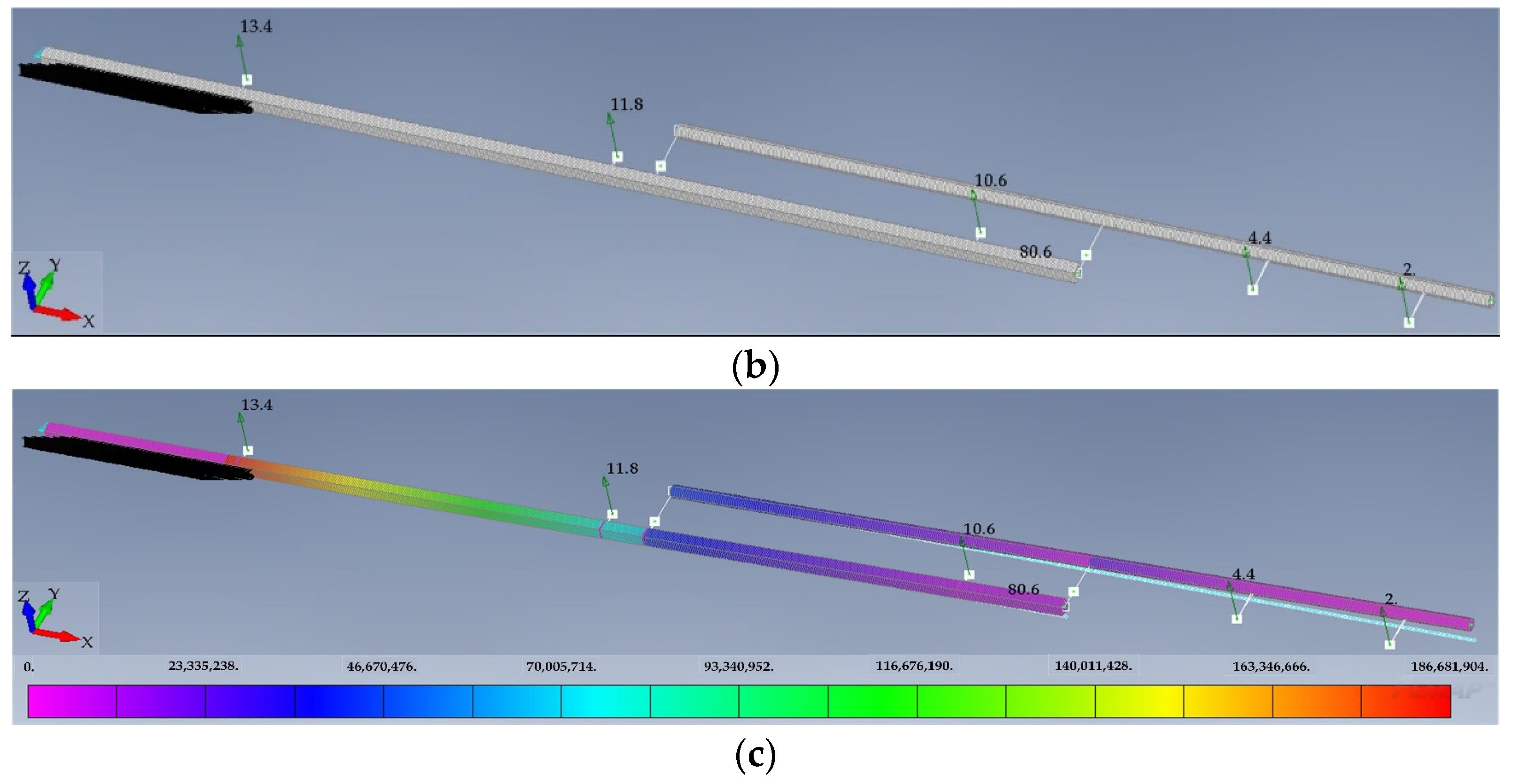
4.2. Spars
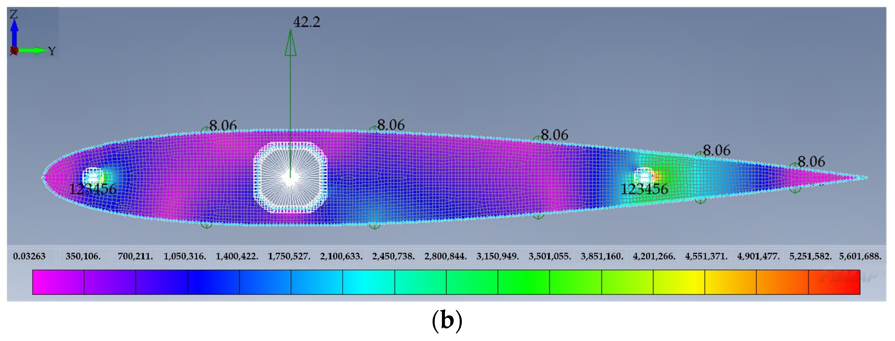
4.3. Ribs
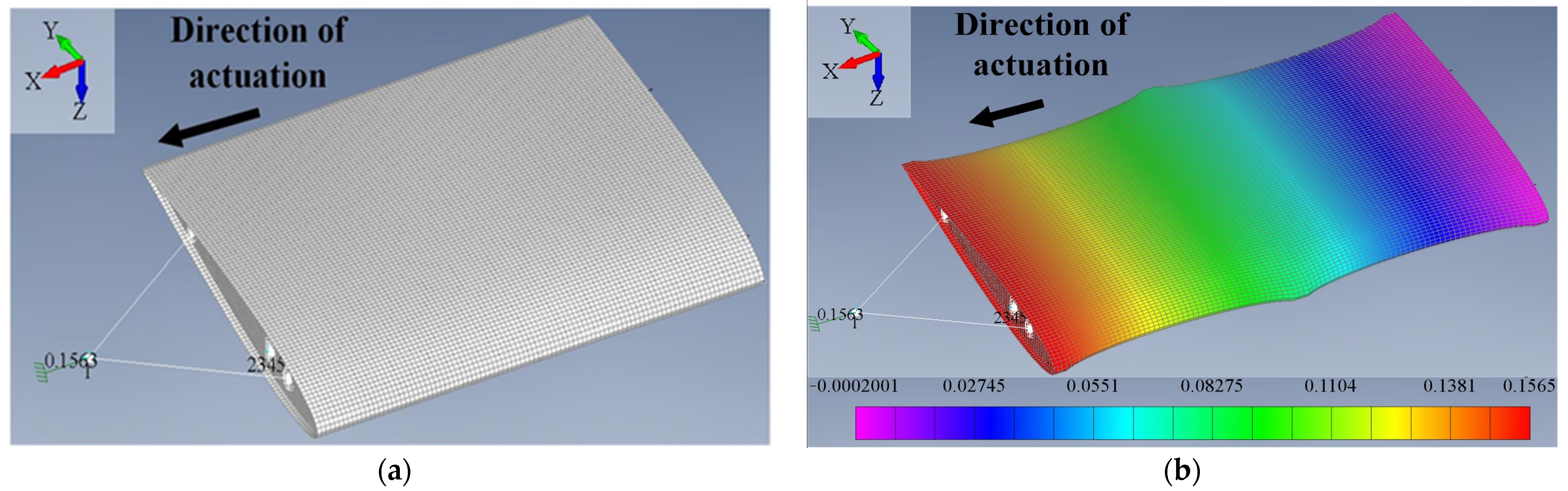
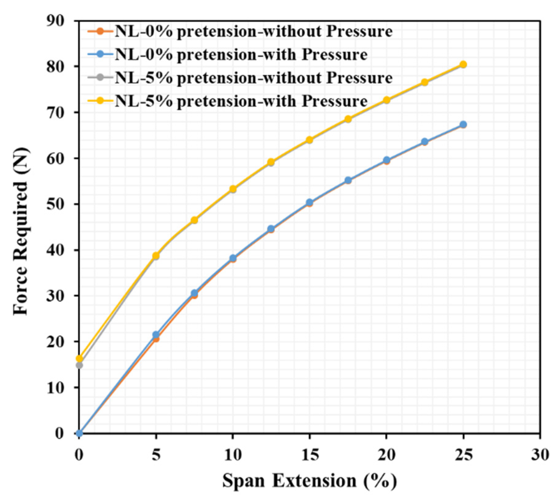
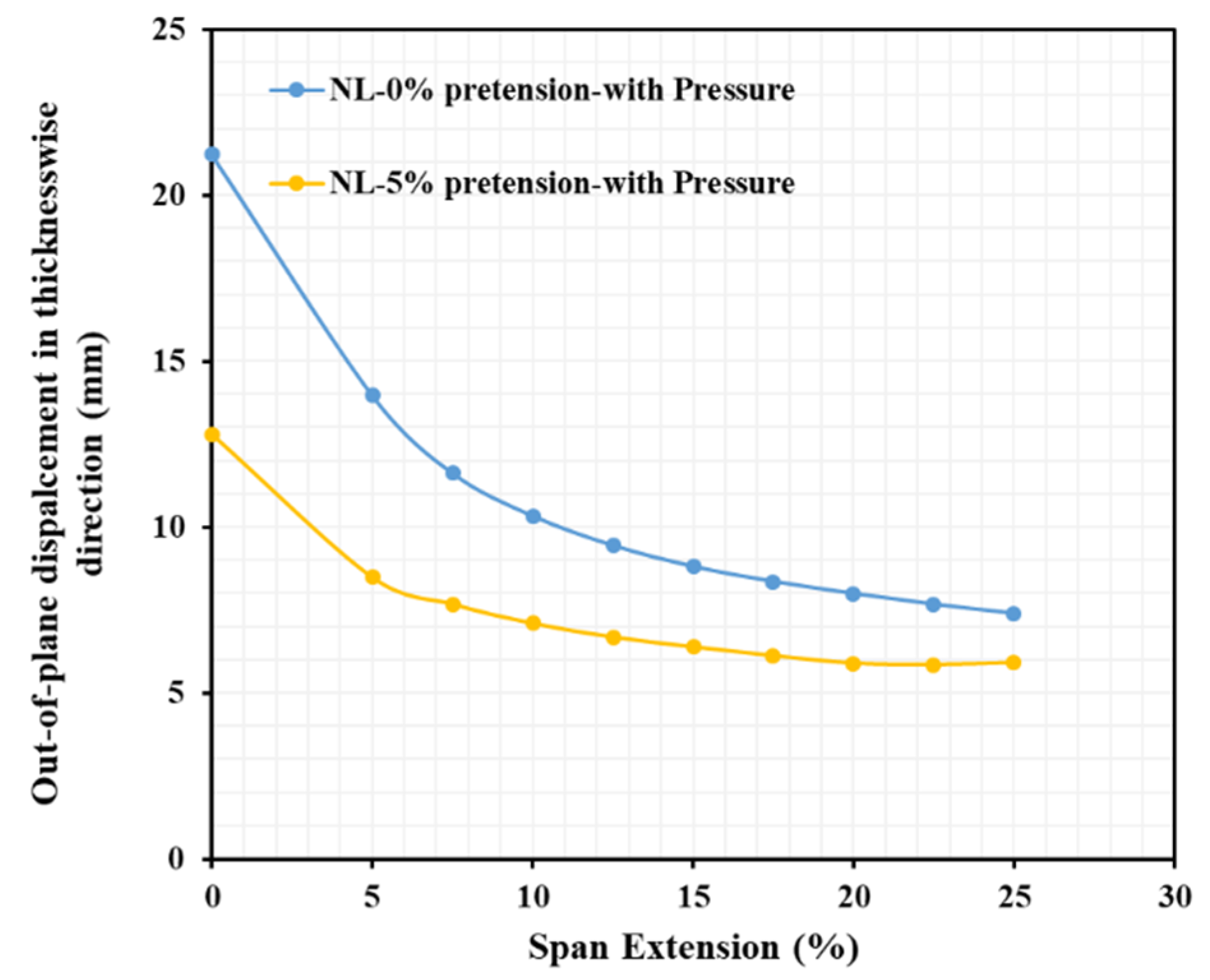
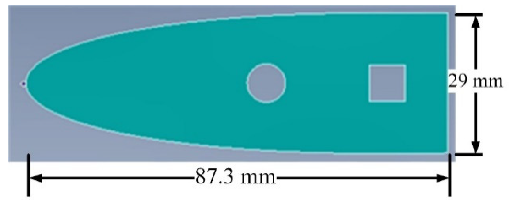
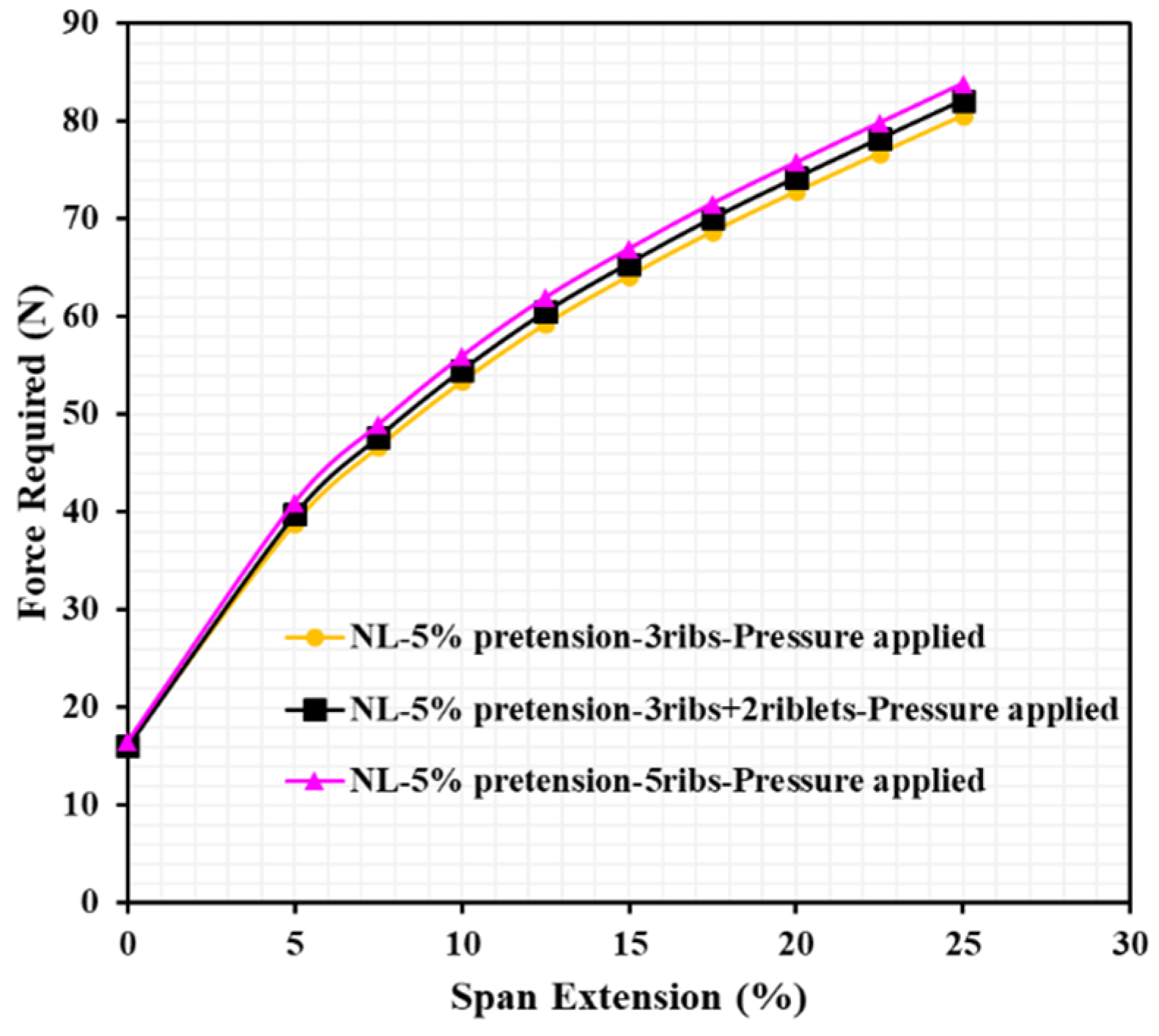
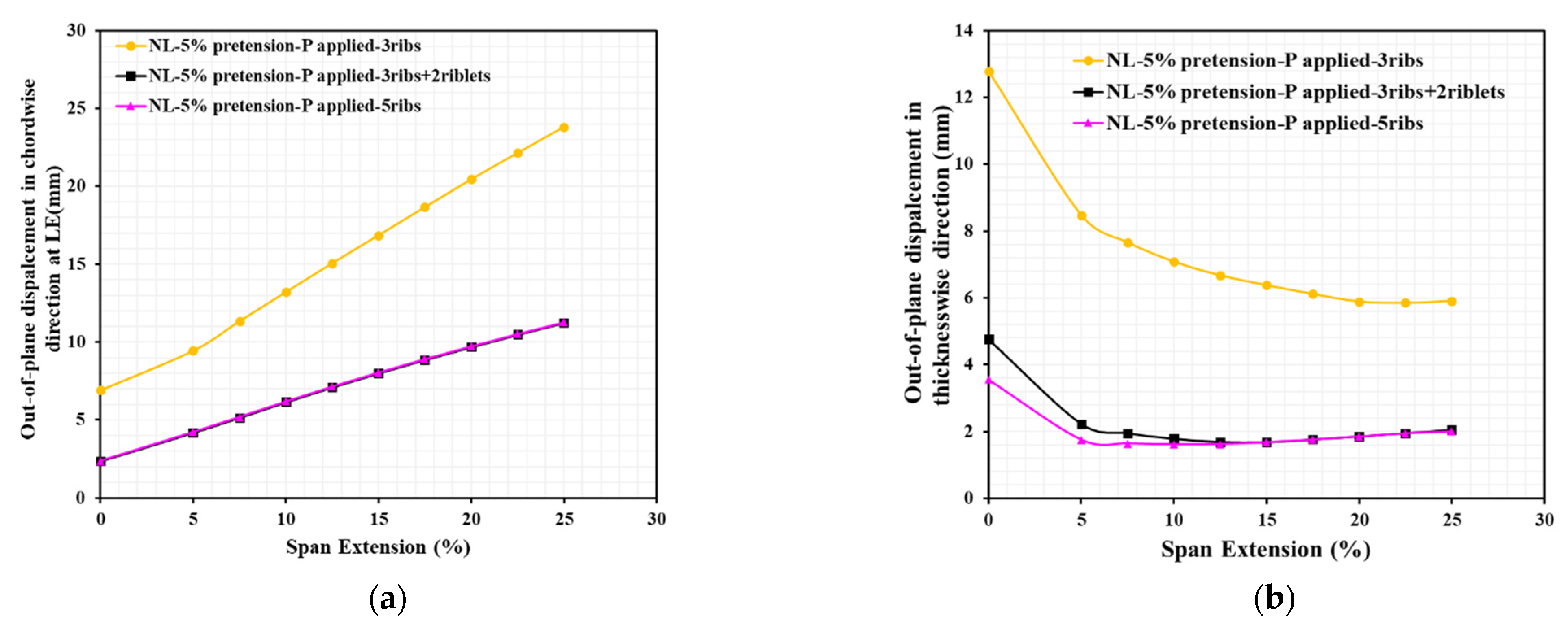
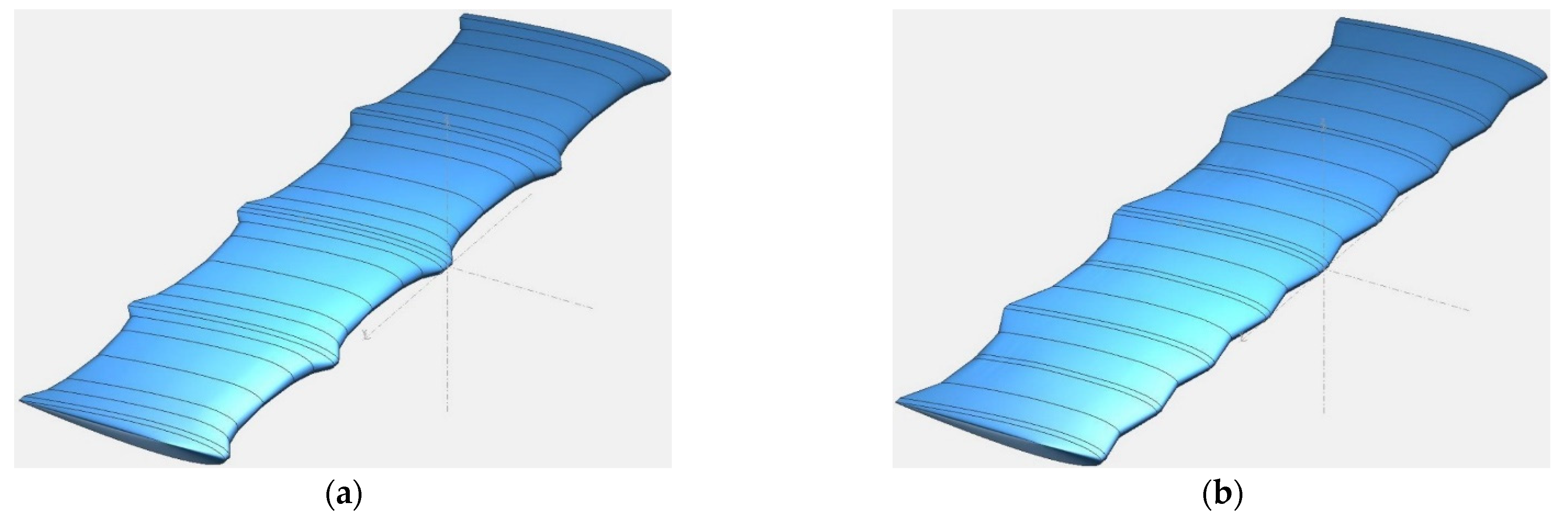
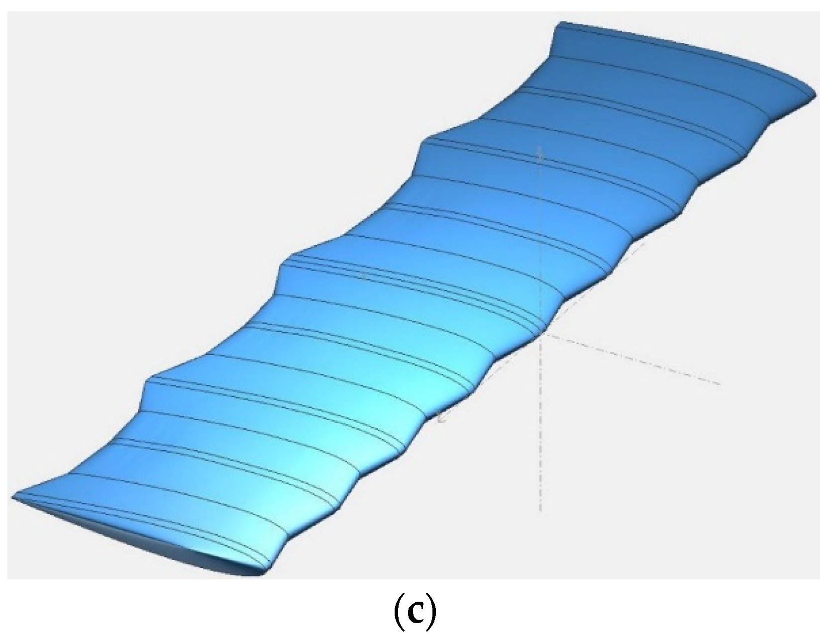
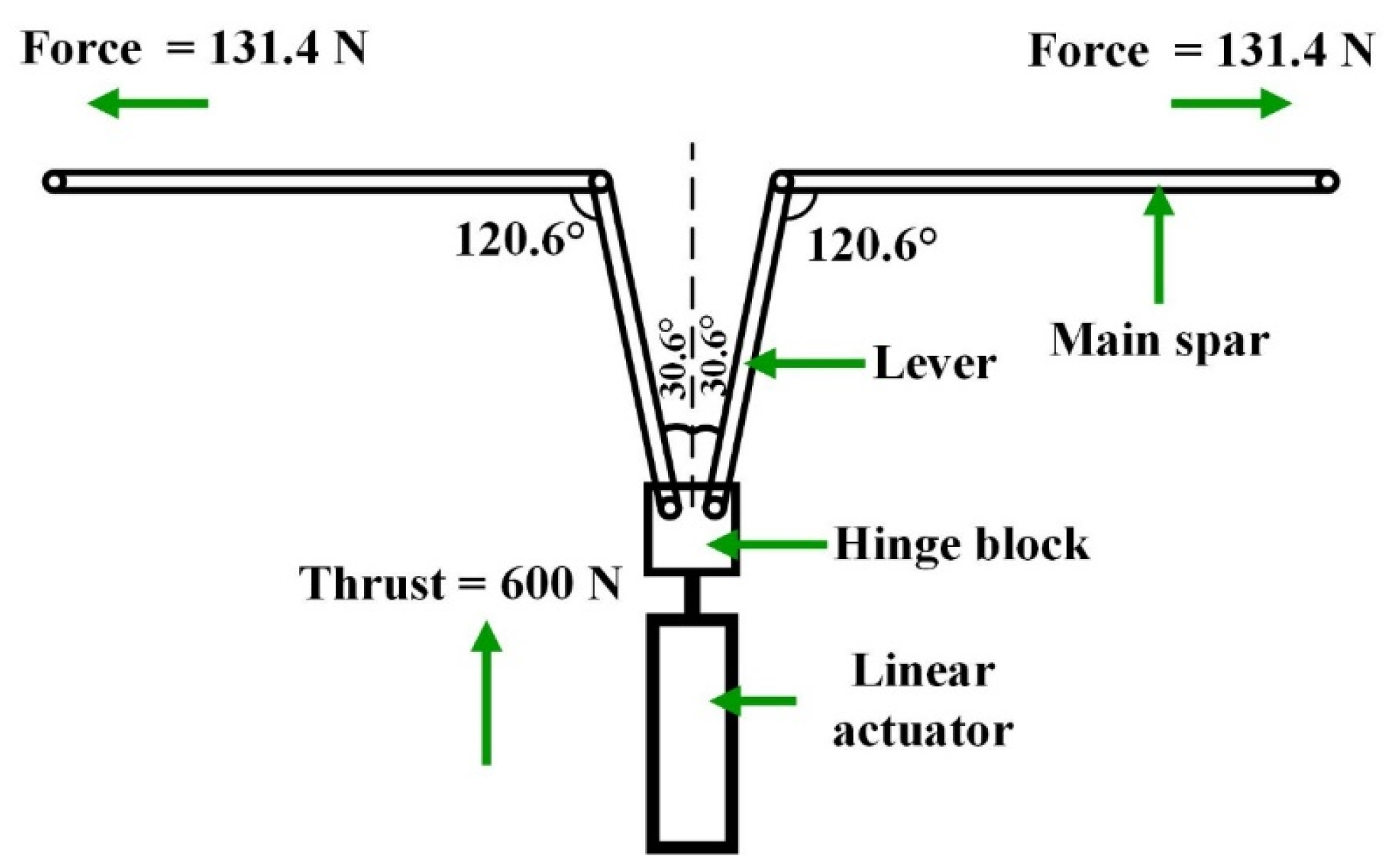
4.4. Actuation Force and Skin
4.5. Aerodynamics of the Inboard Segment
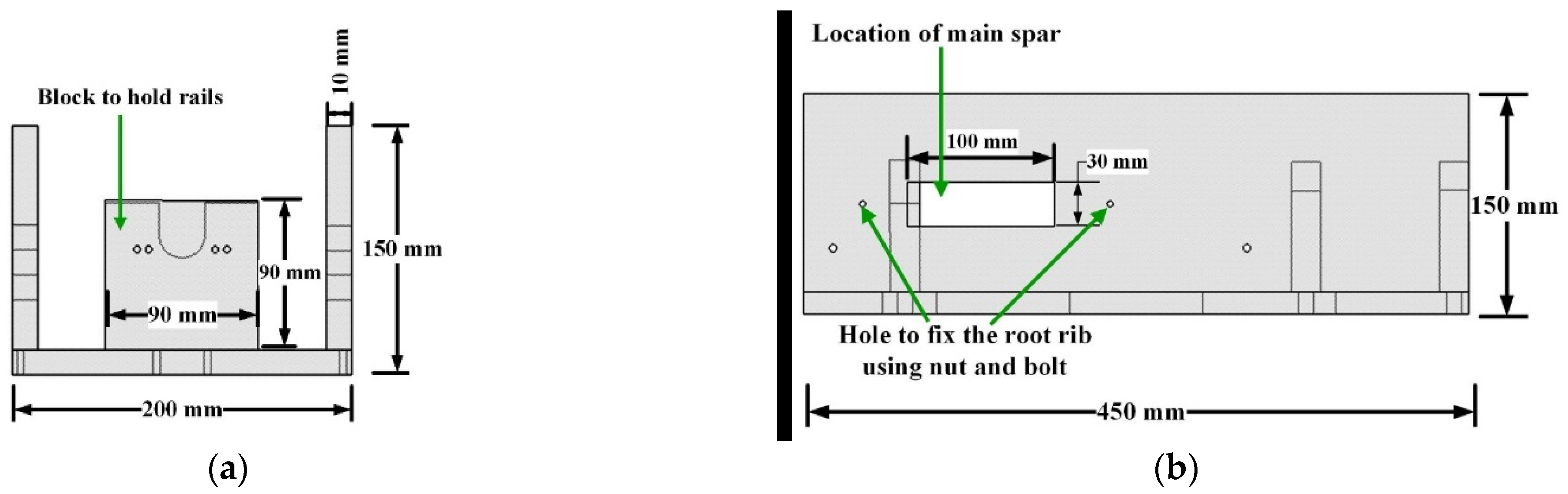
4.6. Fuselage
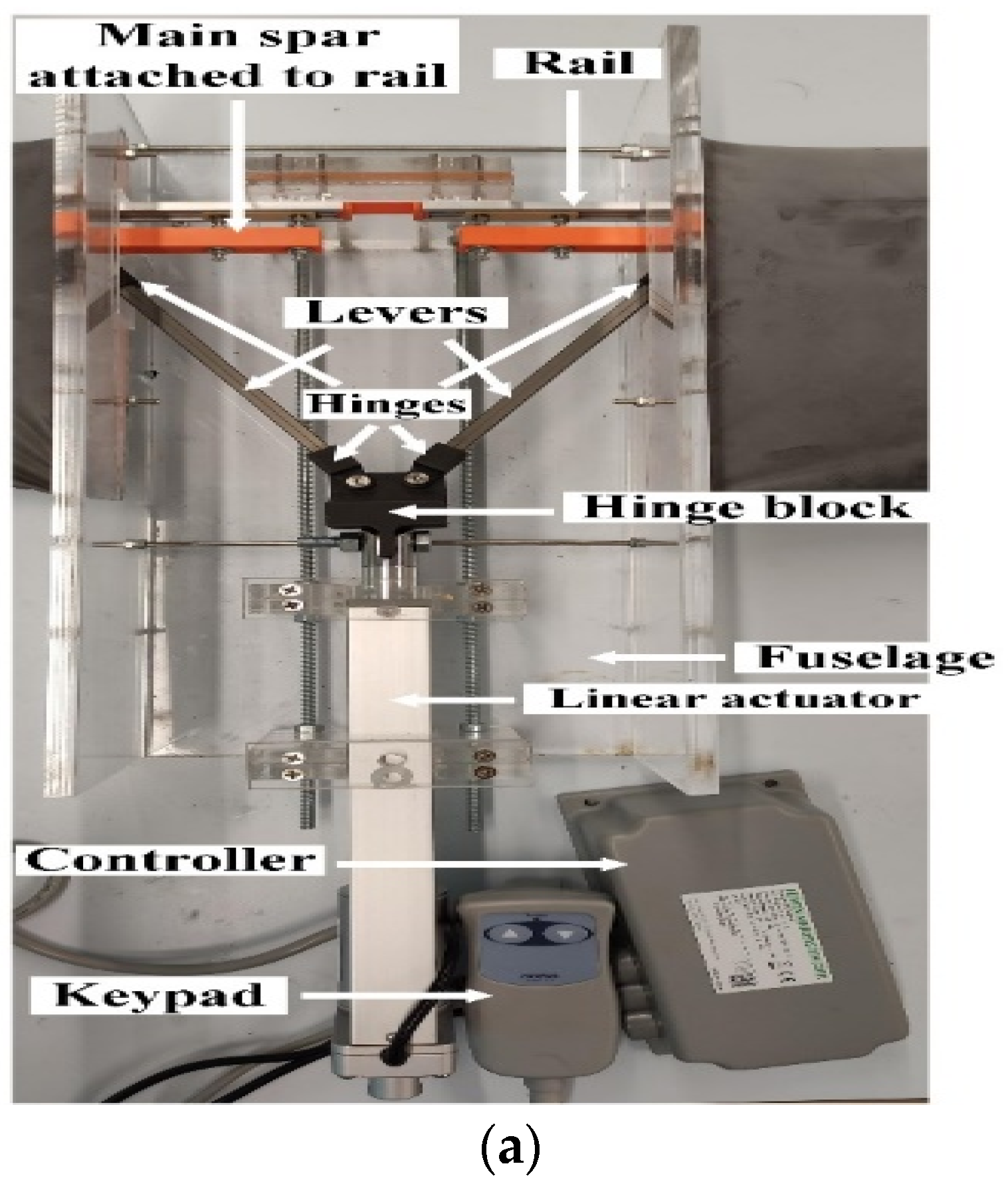
4.7. Linear Actuator
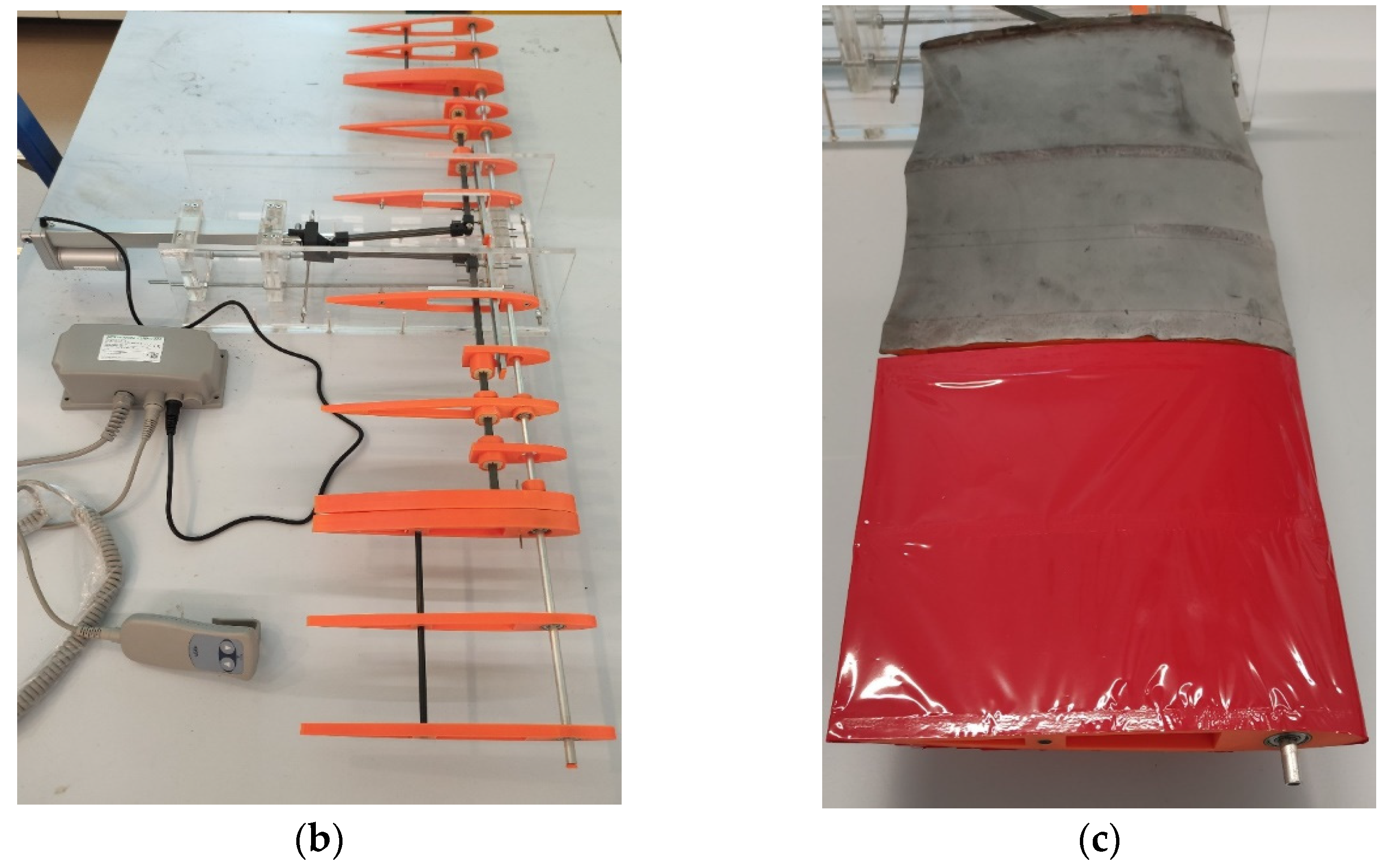
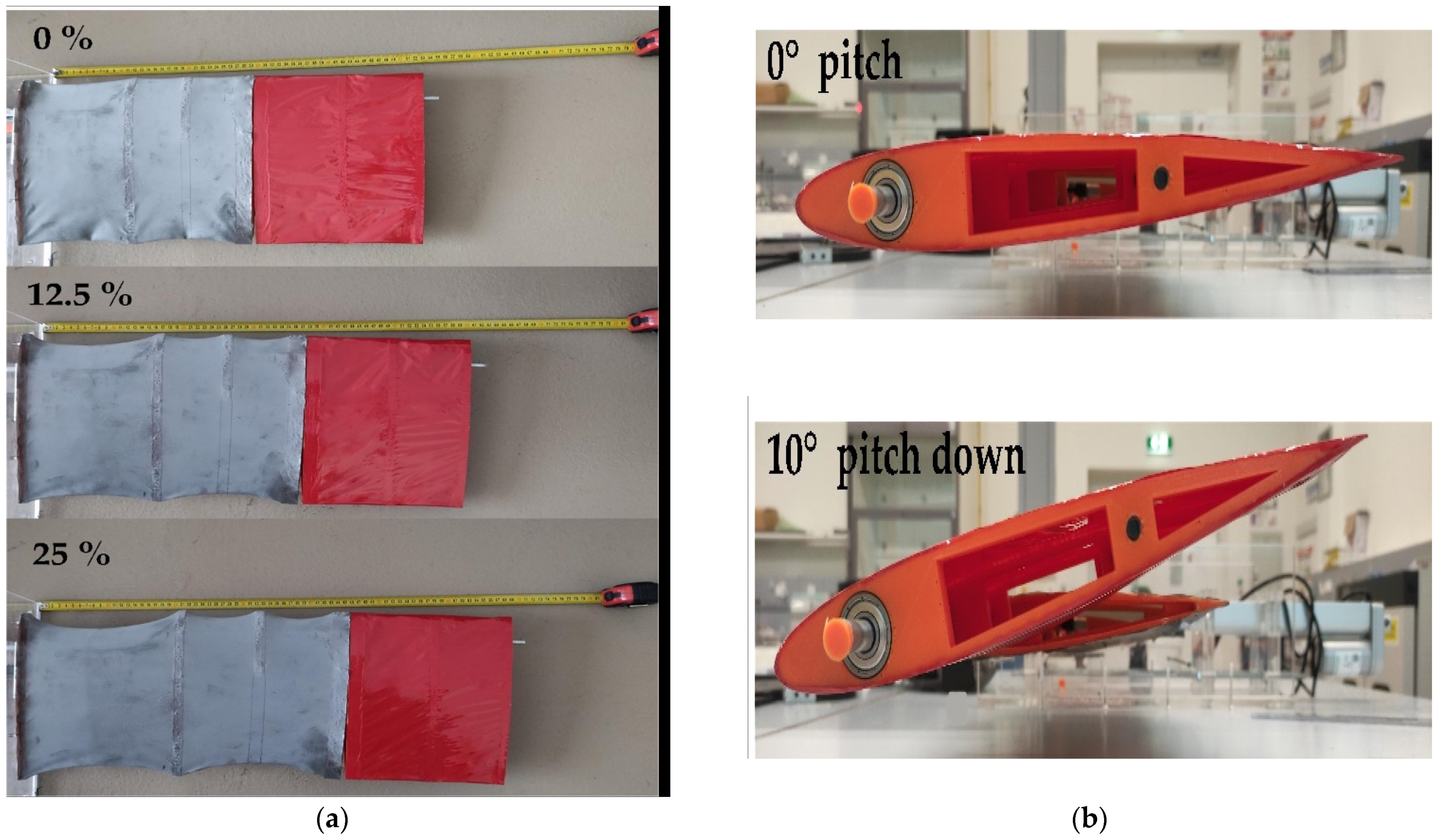
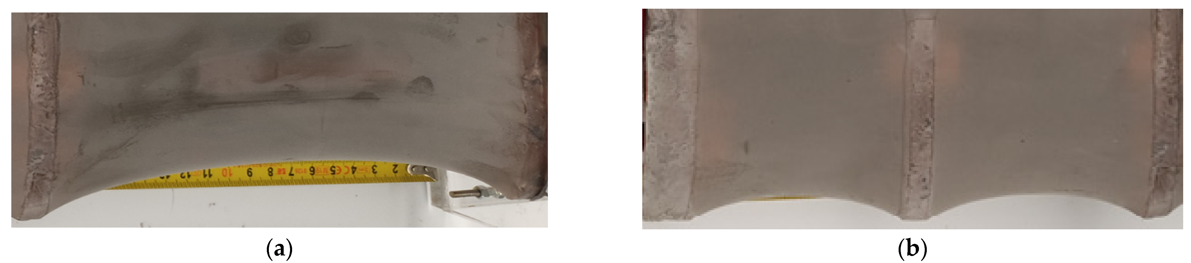
5. Manufacturing and Testing
6. Conclusions and Future Works
Author Contributions
Funding
Institutional Review Board Statement
Informed Consent Statement
Data Availability Statement
Conflicts of Interest
Abbreviations
| Acronyms | |
| ACARE | Advisory Council for Aeronautics Research in Europe |
| AdAR | Adaptive Aspect Ratio |
| ASAPP | Active Span morphing And Passive Pitching |
| EMC | Elastomeric Matrix Composite |
| FOS | Factor Of Safety |
| GNATSpar | Gear-driveN Autonomous Twin-Spar |
| PDMS | Polydimethylsiloxane |
| PLA | Polylactic Acid |
| PTWT | Passive Twist WingTip |
| RBM | Root Bending Moment |
| RSF | Root Shear Force |
| SMA | Shape Memory Alloy |
| VLM | Vortex Lattice Method |
| Nomenclature | |
| CL | coefficient of lift |
| CD | coefficient of drag |
| CM | coefficient of moment |
| L/D | lift/drag |
| angle of attack | |
| I | moment of inertia about elastic axis |
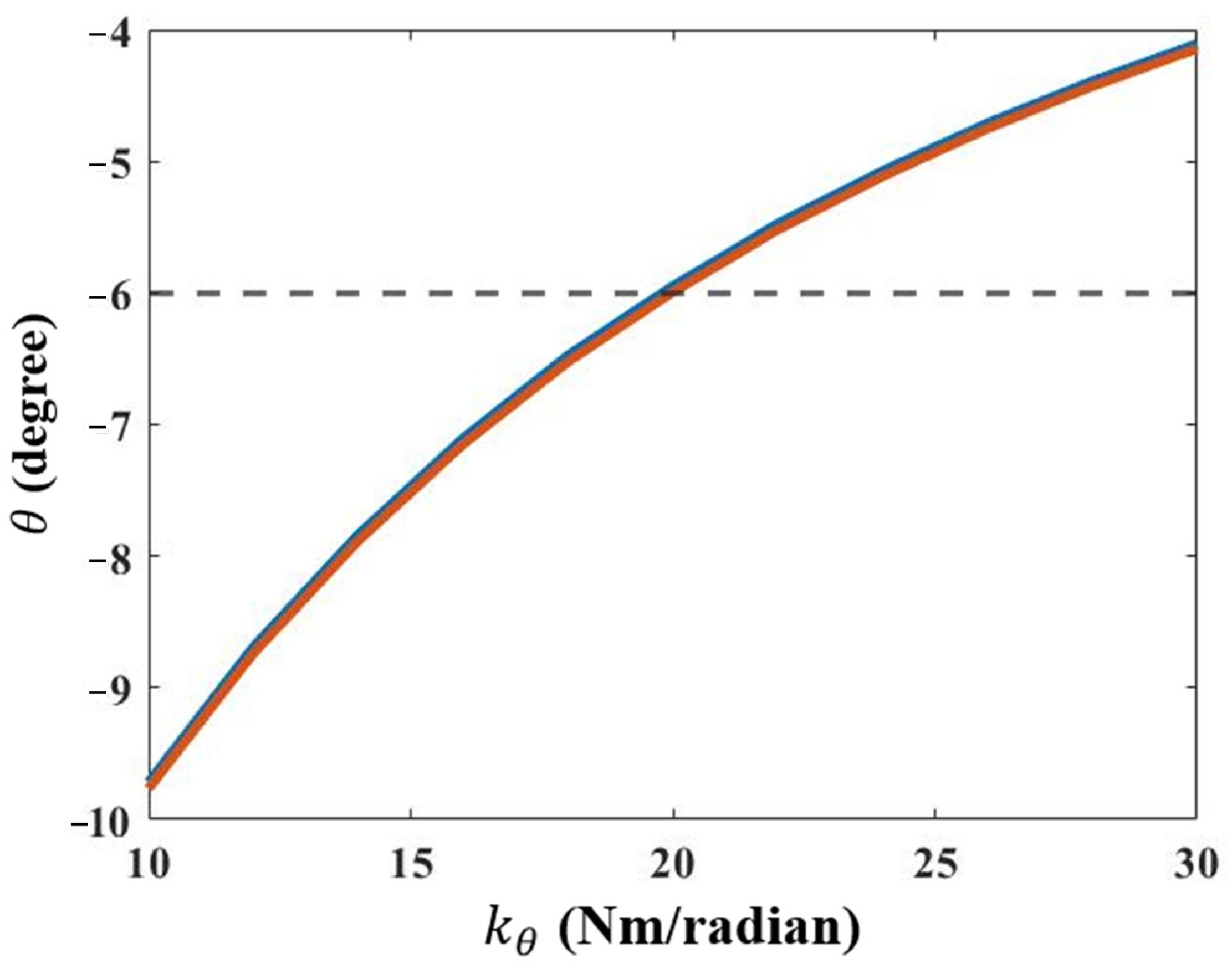
| stiffness of torsional spring | |
| nose-down pitch angle | |
| Mhinge | moment around hinge connecting inboard and outboard wing section |
| fluid density | |
| half chord | |
| V | velocity |
| normalized pitch axis location | |
| Theodorsen’s transfer function | |
| k | reduced frequency |
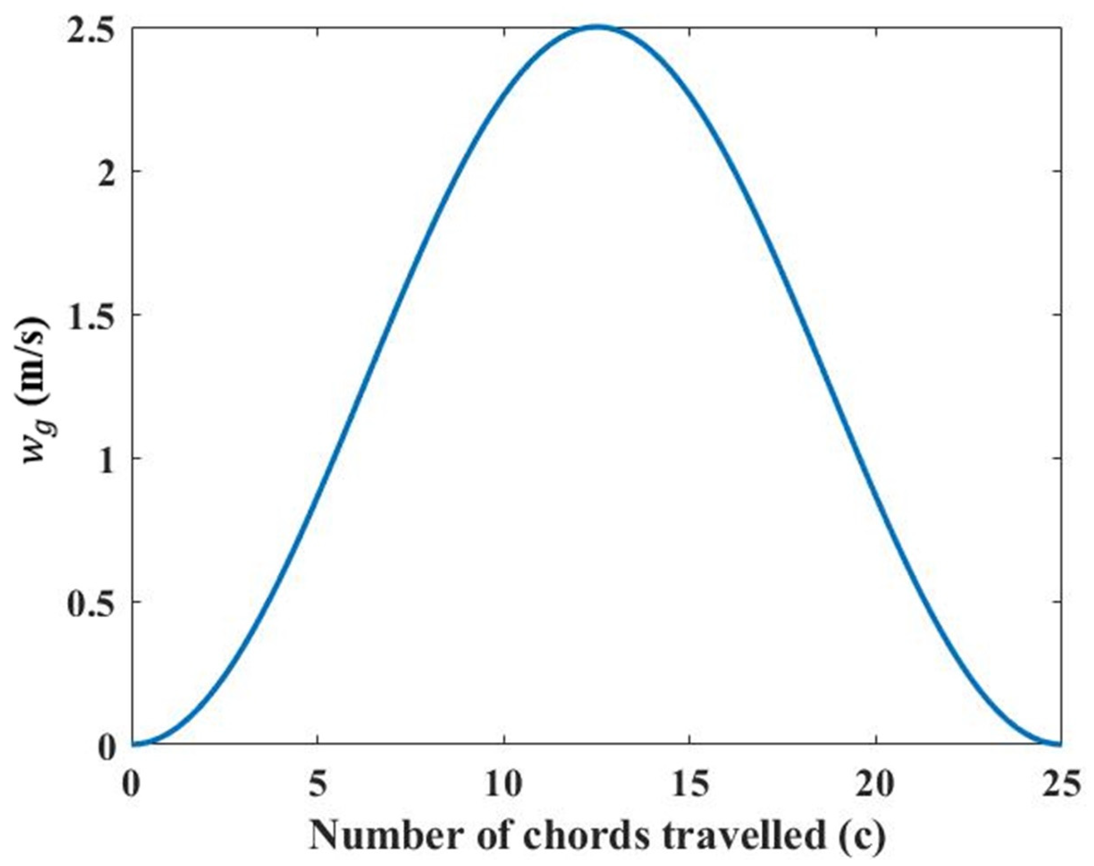
| gust load velocity | |
| maximum gust load velocity | |
| gust gradient | |
References
- Darecki, M.; Edelstenne, C.; Enders, T.; Fernandez, E.; Hartman, P.; Herteman, J.; Kerkloh, M.; King, I.; Ky, P.; Mathieu, M.; et al. Flightpath 2050: Europe’s Vision for Aviation Maintaining Global Leadership and Serving Society’s Needs; Publications Office of the European Union: Luxembourg, 2011. [Google Scholar]
- Olivett, A.; Corrao, P.; Karami, M.A. Flow Control and Separation Delay in Morphing Wing Aircraft Using Traveling Wave Actuation. In Proceedings of the ASME 2020 Conference on Smart Materials, Adaptive Structures and Intelligent Systems, Online, 15 September 2020. [Google Scholar]
- Olivett, A.; Corrao, P.; Karami, M.A. Flow control and separation delay in morphing wing aircraft using traveling wave actuation. Smart Mater. Struct. 2021, 30, 025028. [Google Scholar] [CrossRef]
- Wang, X.; Zhou, W.; Xun, G.; Wu, Z. Dynamic shape control of piezocomposite-actuated morphing wings with vibration suppression. J. Intell. Mater. Syst. Struct. 2018, 29, 358–370. [Google Scholar] [CrossRef]
- Ajaj, R.M.; Parancheerivilakkathil, M.S.; Amoozgar, M.; Friswell, M.I.; Cantwell, W.J. Recent developments in the aeroelasticity of morphing aircraft. Prog. Aerosp. Sci. 2021, 120, 100682. [Google Scholar] [CrossRef]
- Ouyang, Y.; Gu, Y.; Kou, X.; Yang, Z. Active flutter suppression of wing with morphing flap. Aerosp. Sci. Technol. 2021, 110, 106457. [Google Scholar] [CrossRef]
- Selim, O.; Gowree, E.R.; Lagemann, C.; Talboys, E.; Jagadeesh, C.; Brücker, C. Peregrine Falcon’s Dive: Pullout Maneuver and Flight Control Through Wing Morphing. AIAA J. 2021, 59, 3979–3987. [Google Scholar] [CrossRef]
- Rütten, M.; Dölle, B.; Rein, M.; Künemund, J.; Saalfeld, S. Numerical flow investigation of morphing leading edges for the enhancement of maneuverability of unmanned combat air vehicles. In Proceedings of the 30th AIAA Applied Aerodynamics Conference, New Orleans, LA, USA, 25–28 June 2012; p. 3326. [Google Scholar]
- Li, D.; Zhao, S.; Da Ronch, A.; Xiang, J.; Drofelnik, J.; Li, Y.; Zhang, L.; Wu, Y.; Kintscher, M.; Monner, H.P. A review of modelling and analysis of morphing wings. Prog. Aerosp. Sci. 2018, 100, 46–62. [Google Scholar] [CrossRef] [Green Version]
- McCormick, B.W. Aerodynamics, Aeronautics and Flight Mechanics, 2nd ed.; Wiley: New York, NY, USA, 1995; ISBN 0-471-30899-4. [Google Scholar]
- Weisshaar, T.A. Morphing Aircraft Technology-New Shapes for Aircraft Design; Purdue University: West Lafayette, IN, USA, 2006. [Google Scholar]
- Ajaj, R.M.; Jankee, G.K. The Transformer aircraft: A multimission unmanned aerial vehicle capable of symmetric and asymmetric span morphing. Aerosp. Sci. Technol. 2018, 76, 512–522. [Google Scholar] [CrossRef] [Green Version]
- Samuel, J.B.; Pines, D. Design and testing of a pneumatic telescopic wing for unmanned aerial vehicles. J. Aircr. 2007, 44, 1088–1099. [Google Scholar] [CrossRef]
- Ajaj, R.; Flores, E.S.; Friswell, M.; Allegri, G.; Woods, B.; Isikveren, A.; Dettmer, W. The Zigzag wingbox for a span morphing wing. Aerosp. Sci. Technol. 2013, 28, 364–375. [Google Scholar] [CrossRef]
- Ajaj, R.; Friswell, M.; Bourchak, M.; Harasani, W. Span morphing using the GNATSpar wing. Aerosp. Sci. Technol. 2016, 53, 38–46. [Google Scholar] [CrossRef] [Green Version]
- Vocke, R.D., III; Kothera, C.S.; Woods, B.K.; Wereley, N.M. Development and testing of a span-extending morphing wing. J. Intell. Mater. Syst. Struct. 2011, 22, 879–890. [Google Scholar] [CrossRef]
- Bubert, E.A.; Woods, B.K.; Lee, K.; Kothera, C.S.; Wereley, N. Design and fabrication of a passive 1D morphing aircraft skin. J. Intell. Mater. Syst. Struct. 2010, 21, 1699–1717. [Google Scholar] [CrossRef]
- Woods, B.K.; Friswell, M.I. The Adaptive Aspect Ratio morphing wing: Design concept and low fidelity skin optimization. Aerosp. Sci. Technol. 2015, 42, 209–217. [Google Scholar] [CrossRef]
- Woods, B.K.S.; Friswell, M.I. The Adaptive Aspect Ratio Morphing Wing: Design Concept and Low Fidelity Skin Optimization. In Proceedings of the Smart Materials, Adaptive Structures and Intelligent Systems, Newport, RI, USA, 8–10 September 2014; p. V002T004A027. [Google Scholar]
- Bishay, P.L.; Burg, E.; Akinwunmi, A.; Phan, R.; Sepulveda, K. Development of a new span-morphing wing core design. Designs 2019, 3, 12. [Google Scholar] [CrossRef] [Green Version]
- Geva, A.; Abramovich, H.; Arieli, R. Investigation of a Morphing Wing Capable of Airfoil and Span Adjustment Using a Retractable Folding Mechanism. Aerospace 2019, 6, 85. [Google Scholar] [CrossRef] [Green Version]
- Vos, R.; Gürdal, Z.; Abdalla, M. Mechanism for warp-controlled twist of a morphing wing. J. Aircr. 2010, 47, 450–457. [Google Scholar] [CrossRef]
- Rodrigue, H.; Cho, S.; Han, M.-W.; Bhandari, B.; Shim, J.-E.; Ahn, S.-H. Effect of twist morphing wing segment on aerodynamic performance of UAV. J. Mech. Sci. Technol. 2016, 30, 229–236. [Google Scholar] [CrossRef]
- Rodrigue, H.; Bhandari, B.; Han, M.-W.; Ahn, S.-H. A shape memory alloy–based soft morphing actuator capable of pure twisting motion. J. Intell. Mater. Syst. Struct. 2015, 26, 1071–1078. [Google Scholar] [CrossRef]
- Schlup, A.; Bishay, P.; Mclennan, T.; Barajas, C.; Talebian, B.; Thatcher, G.; Flores, R.; Perez-Norwood, J.; Torres, C.; Kibret, K. MataMorph 2: A new experimental UAV with twist-morphing wings and camber-morphing tail stabilizers. In Proceedings of the AIAA Scitech 2021 Forum, Virtual Event, 11–15 & 19–21 January 2021; p. 0584. [Google Scholar]
- Rea, F.; Amoroso, F.; Pecora, R.; Moens, F. Exploitation of a multifunctional twistable wing trailing-edge for performance improvement of a turboprop 90-seats regional aircraft. Aerospace 2018, 5, 122. [Google Scholar] [CrossRef] [Green Version]
- Cambier, L.; Heib, S.; Plot, S. The Onera elsA CFD software: Input from research and feedback from industry. Mech. Ind. 2013, 14, 159–174. [Google Scholar] [CrossRef] [Green Version]
- Bishay, P.L.; Aguilar, C. Parametric study of a composite skin for a twist-morphing wing. Aerospace 2021, 8, 259. [Google Scholar] [CrossRef]
- Guo, S.; Los Monteros, D.; Espinosa, J.; Liu, Y. Gust alleviation of a large aircraft with a passive twist wingtip. Aerospace 2015, 2, 135–154. [Google Scholar] [CrossRef] [Green Version]
- Ajaj, R.; Parancheerivilakkathil, M.S.; Amoozgar, M. ASAPP: A polymorphing wing capable of Active Span extension And Passive Pitch. In Proceedings of the AIAA Scitech 2021 Forum, Virtual Event, 11–15 & 19–21 January 2021; p. 0621. [Google Scholar]
- Agten, M. Aerodynamic Analysis of Wings in Airborne Wind Energy Applications: A 3D Potential Flow Solver Extended with a Viscous Correction to Predict Non-Linear Lift and Drag Coefficients at High AoA; Delft University of Technology: Delft, The Netherlands, 2012. [Google Scholar]
- Gavrilovic, N.; Abrantes, G.; Kirsch, B.; Pastor, P.; Benard, E. Passive Gust Energy Extraction of Small UAVs. In Proceedings of the 53nd 3AF International Conference on Applied Aerodynamics, FP45-2018-gavrilovic, Salon-de-Provence, France, 26–28 March 2018. [Google Scholar]
- Parancheerivilakkathil, M.S.; Ajaj, R.M.; Khan, K.A. A compliant polymorphing wing for small UAVs. Chin. J. Aeronaut. 2020, 33, 2575–2588. [Google Scholar] [CrossRef]
- Ahmad, D.; Ajaj, R.M. Multiaxial mechanical characterization of latex skin for morphing wing application. Polym. Test. 2022, 106, 107408. [Google Scholar] [CrossRef]


| Span Extension | (Degree) | Pitch Angle (Degree) | RBM (Nm) | % Change in RBM | CD | % Change in CD |
|---|---|---|---|---|---|---|
| 0% | 6.88 | 0 | 5.4 | 0.00 | 0.02596 | 0.00 |
| 7 | 0.5 | 5.33 | −1.30 | 0.02568 | −1.10 | |
| 8 | 3.6 | 4.96 | −8.15 | 0.02641 | 1.74 | |
| 9 | 7 | 4.58 | −15.19 | 0.02897 | 11.60 | |
| 25% | 6 | 3.5 | 6.13 | 13.52 | 0.02257 | −13.06 |
| 7 | 8.2 | 5.41 | 0.19 | 0.02501 | −3.66 | |
| 37.50% | 5 | 1.9 | 7.01 | 29.81 | 0.02109 | −18.76 |
| 50% | 5 | 5 | 7 | 29.63 | 0.02134 | −17.81 |
| Span | (deg) | (deg) | With Passive Pitching | Without Passive Pitching | ||||||
|---|---|---|---|---|---|---|---|---|---|---|
| 1-g Loading | During Gust | 1-g Loading | During Gust | |||||||
| RBM (Nm) | RSF (N) | RBM (Nm) | RSF (N) | RBM (Nm) | RSF (N) | RBM (Nm) | RSF (N) | |||
| 0% span | 6.93 | −0.26 | 5.42 | 18.3 | 9.04 | 32.3 | 5.52 | 18.6 | 11.62 | 38.2 |
| 25% span | 6.09 | −0.4 | 7.83 | 21.1 | 14.56 | 40.7 | 8.05 | 21.52 | 18.01 | 47.4 |
Publisher’s Note: MDPI stays neutral with regard to jurisdictional claims in published maps and institutional affiliations. |
© 2022 by the authors. Licensee MDPI, Basel, Switzerland. This article is an open access article distributed under the terms and conditions of the Creative Commons Attribution (CC BY) license (https://creativecommons.org/licenses/by/4.0/).
Share and Cite
Parancheerivilakkathil, M.S.; Haider, Z.; Ajaj, R.M.; Amoozgar, M. A Polymorphing Wing Capable of Span Extension and Variable Pitch. Aerospace 2022, 9, 205. https://doi.org/10.3390/aerospace9040205
Parancheerivilakkathil MS, Haider Z, Ajaj RM, Amoozgar M. A Polymorphing Wing Capable of Span Extension and Variable Pitch. Aerospace. 2022; 9(4):205. https://doi.org/10.3390/aerospace9040205
Chicago/Turabian StyleParancheerivilakkathil, Muhammed S., Zawar Haider, Rafic M. Ajaj, and Mohammadreza Amoozgar. 2022. "A Polymorphing Wing Capable of Span Extension and Variable Pitch" Aerospace 9, no. 4: 205. https://doi.org/10.3390/aerospace9040205