
Parametric Investigation of a Distributed Propulsion System on a Regional Aircraft


Abstract
:1. Introduction
2. Computational Analysis
2.1. Grid Generation
2.2. CFD Evaluation
2.3. Boundary Conditions
2.4. Test Matrix
3. Results
3.1. Flap A Working Conditions
3.2. Flap B Working Conditions
4. Conclusions
Author Contributions
Funding
Institutional Review Board Statement
Informed Consent Statement
Data Availability Statement
Conflicts of Interest
References
- Darecki, M.; Edelstenne, C.; Enders, T.; Fernandez, E.; Hartman, P.; Herteman, J.P.; Kerkloh, M.; King, I.; Ky, P.; Mathieu, M.; et al. Flightpath 2050. 2011, p. 28. Available online: https://op.europa.eu/en/publication-detail/-/publication/7d834950-1f5e-480f-ab70-ab96e4a0a0ad/language-en (accessed on 1 February 2022). [CrossRef]
- Kim, H.D.; Brown, G.V.; Felder, J.L. Distributed Turboelectric Propulsion for Hybrid Wing Body Aircraft. In Proceedings of the 2008 International Powered Lift Conference Royal Aeronautical Society, London, UK, 20–24 July 2008. [Google Scholar]
- Armstrong, M.J.; Ross, C.A.H.; Blackwelder, M.J.; Rajashekara, K. Trade Studies for NASA N3-X Turboelectric Distributed Propulsion System Electrical Power System Architecture. SAE Int. J. Aerosp. 2012, 5, 325. [Google Scholar] [CrossRef]
- Airbus. Airbus Reveals New Zero-Emission Concept Aircraft. 2020. Available online: https://www.airbus.com/en/newsroom/press-releases/2020-09-airbus-reveals-new-zero-emission-concept-aircraft (accessed on 1 February 2022).
- Felder, J.; Tong, M.; Chu, J. Sensitivity of Mission Energy Consumption to Turboelectric Distributed Propulsion Design Assumptions on the N3-X Hybrid Wing Body Aircraft. In Proceedings of the 48th AIAA/ASME/SAE/ASEE Joint Propulsion Conference & Exhibit, Atlanta, GA, USA, 30 July–1 August 2012; American Institute of Aeronautics and Astronautics: Reston, VA, USA, 2012. [Google Scholar] [CrossRef] [Green Version]
- Choi, B.; Brown, G.V.; Morrison, C.; Dever, T. Propulsion Electric Grid Simulator (PEGS) for Future Turboelectric Distributed Propulsion Aircraft. In Proceedings of the 12th International Energy Conversion Engineering Conference, Cleveland, OH, USA, 28–30 July 2014; American Institute of Aeronautics and Astronautics: Reston, VA, USA, 2014. [Google Scholar] [CrossRef] [Green Version]
- Berton, J.J.; Haller, W.J. A Noise and Emissions Assessment of the N3-X Transport. In Proceedings of the 52nd Aerospace Sciences Meeting, Prince George’s County, MD, USA, 13–17 January 2014; American Institute of Aeronautics and Astronautics: Reston, VA, USA, 2014. [Google Scholar] [CrossRef] [Green Version]
- Hermetz, J.; Ridel, M.; Doll, C. Distributed electric propulsion for small business aircraft a concept-plane for key-technologies investigations. In Proceedings of the Twelfth International Conference on Autonomic and Autonomous Systems, ICAS 2016, Lisbon, Portugal, 26–30 June 2016; p. 10. [Google Scholar]
- Thauvin, J.; Barraud, G.; Budinger, M.; Roboam, X.; Leray, D.; Sareni, B. Hybrid Regional Aircraft: A Comparative Review of New Potentials Enabled by Electric Power. In Proceedings of the 52nd AIAA/SAE/ASEE Joint Propulsion Conference, Salt Lake City, UT, USA, 25–27 July 2016; American Institute of Aeronautics and Astronautics: Reston, VA, USA, 2016. [Google Scholar] [CrossRef] [Green Version]
- Stoll, A.M.; Bevirt, J.B.; Moore, M.D.; Fredericks, W.J.; Borer, N.K. Drag reduction through distributed electric propulsion. In Proceedings of the AIAA AVIATION 2014—14th AIAA Aviation Technology, Integration, and Operations Conference, Atlanta, GA, USA, 16–20 June 2014; American Institute of Aeronautics and Astronautics: Reston, VA, USA, 2014. [Google Scholar] [CrossRef] [Green Version]
- Kim, H.D.; Perry, A.T.; Ansell, P.J. A Review of Distributed Electric Propulsion Concepts for Air Vehicle Technology. In Proceedings of the 2018 AIAA/IEEE Electric Aircraft Technologies Symposium, EATS 2018, Cincinnati, OH, USA, 12–14 July 2018; American Institute of Aeronautics and Astronautics: Reston, VA, USA, 2018. [Google Scholar] [CrossRef] [Green Version]
- Dubois, A.; van der Geest, M.; Bevirt, J.; Christie, R.; Borer, N.K.; Clarke, S.C. Design of an Electric Propulsion System for SCEPTOR’s Outboard Nacelle. In Proceedings of the 16th AIAA Aviation Technology, Integration, and Operations Conference, Washington, DC, USA, 13–17 June 2016; American Institute of Aeronautics and Astronautics: Reston, VA, USA, 2016. [Google Scholar] [CrossRef]
- Deere, K.A.; Viken, J.K.; Viken, S.; Carter, M.B.; Wiese, M.; Farr, N. Computational Analysis of a Wing Designed for the X-57 Distributed Electric Propulsion Aircraft. In Proceedings of the 35th AIAA Applied Aerodynamics Conference, Denver, CO, USA, 5–9 June 2017; American Institute of Aeronautics and Astronautics: Reston, VA, USA, 2017. [Google Scholar] [CrossRef]
- Patterson, M.D.; Daskilewicz, M.J.; German, B. Simplified Aerodynamics Models to Predict the Effects of Upstream Propellers on Wing Lift. In Proceedings of the 53rd AIAA Aerospace Sciences Meeting, Kissimmee, FL, USA, 5–9 January 2015; American Institute of Aeronautics and Astronautics: Reston, VA, USA, 2015. [Google Scholar] [CrossRef]
- Patterson, M.D.; Derlaga, J.M.; Borer, N.K. High-Lift Propeller System Configuration Selection for NASA’s SCEPTOR Distributed Electric Propulsion Flight Demonstrator. In Proceedings of the 16th AIAA Aviation Technology, Integration, and Operations Conference, Washington, DC, USA, 13–17 June 2016; American Institute of Aeronautics and Astronautics: Reston, VA, USA, 2016. [Google Scholar] [CrossRef]
- Čerňan, J.; Janovec, M.; Škultéty, F. The stress analysis of air turbine driven propeller blade. Transp. Res. Procedia 2020, 51, 293–303. [Google Scholar] [CrossRef]
- Janovec, M.; Čerňan, J.; Škultéty, F.; Novák, A. Design of Batteries for a Hybrid Propulsion System of a Training Aircraft. Energies 2021, 15, 49. [Google Scholar] [CrossRef]
- Burston, M.; Ranasinghe, K.; Gardi, A.; Parezanović, V.; Ajaj, R.; Sabatini, R. Design principles and digital control of advanced distributed propulsion systems. Energy 2022, 241, 122788. [Google Scholar] [CrossRef]
- Raymer, D. Aircraft Design: A Conceptual Approach, 6th ed.; American Institute of Aeronautics and Astronautics, Inc.: Washington, DC, USA, 2018. [Google Scholar] [CrossRef] [Green Version]
- Springer, A.M. (Ed.) Aerospace Design: Aircraft, Spacecraft, and the Art of Modern Flight; Merrell Publisher: London, UK, 2004; Volume 41, pp. 41–4620. [Google Scholar]
- Roskam, J. Airplane Design: Preliminary Sizing of Airplanes; Design, Analysis and Research Corporation: Lawrence, KS, USA, 2015. [Google Scholar]
- Catalano, P.; Amato, M. An evaluation of {RANS} turbulence modelling for aerodynamic applications. Aerosp. Sci. Technol. 2003, 7, 493–509. [Google Scholar] [CrossRef]
- Marongiu, C.; Catalano, P.; Amato, M.; Iaccarino, G. U-{ZEN}: A Computational Tool Solving U-Rans Equations for Industrial Unsteady Applications. In Proceedings of the 34th AIAA Fluid Dynamics Conference and Exhibit, Portland, OR, USA, 28 June–1 July 2004; American Institute of Aeronautics and Astronautics: Reston, VA, USA, 2004. [Google Scholar] [CrossRef]
- Marongiu, C.; Panizza, A.; Vitagliano, P.L. A moving grid method for unsteady flow computations. In Proceedings of the 18th AIAA Computational Fluid Dynamics Conference, Miami, FL, USA, 25–28 June 2007; p. 4470. [Google Scholar]
- Jameson, A. Time dependent calculations using multigrid, with applications to unsteady flows past airfoils and wings. In Proceedings of the 10th Computational Fluid Dynamics Conference, Honolulu, HI, USA, 24–26 June 1991; p. 1596. [Google Scholar]
- Kok, J.C. Resolving the dependence on freestream values for the k-turbulence model. AIAA J. 2000, 38, 1292–1295. [Google Scholar] [CrossRef]
- Vitagliano, P.L. Deliverable D3.3.2-5c: “An Actuator Disk Model for Unsteady Flow Simulations”, CESAR Integrated project AIP5-CT-2006-030888. Technical Report CIRA-CF-10-0023, CIRA. 2010. Available online: https://trimis.ec.europa.eu/sites/default/files/project/documents/20120716_094200_52135_CESAR_Publishable_Activity_Report.pdf (accessed on 1 February 2022).
- Le Chuiton, F. Actuator disc modelling for helicopter rotors. Aerosp. Sci. Technol. 2004, 8, 285–297. [Google Scholar] [CrossRef]
- Gallani, M.A.; Góes, L.C.; Nerosky, L.A. Effects of distributed electric propulsion on the performance of a general aviation aircraft. In Proceedings of the AIAA Propulsion and Energy 2020 Forum, New Orleans, LA, USA, 24–28 August 2020; American Institute of Aeronautics and Astronautics: Reston, VA, USA, 2020; pp. 1–16. [Google Scholar] [CrossRef]


 ) and m/s (
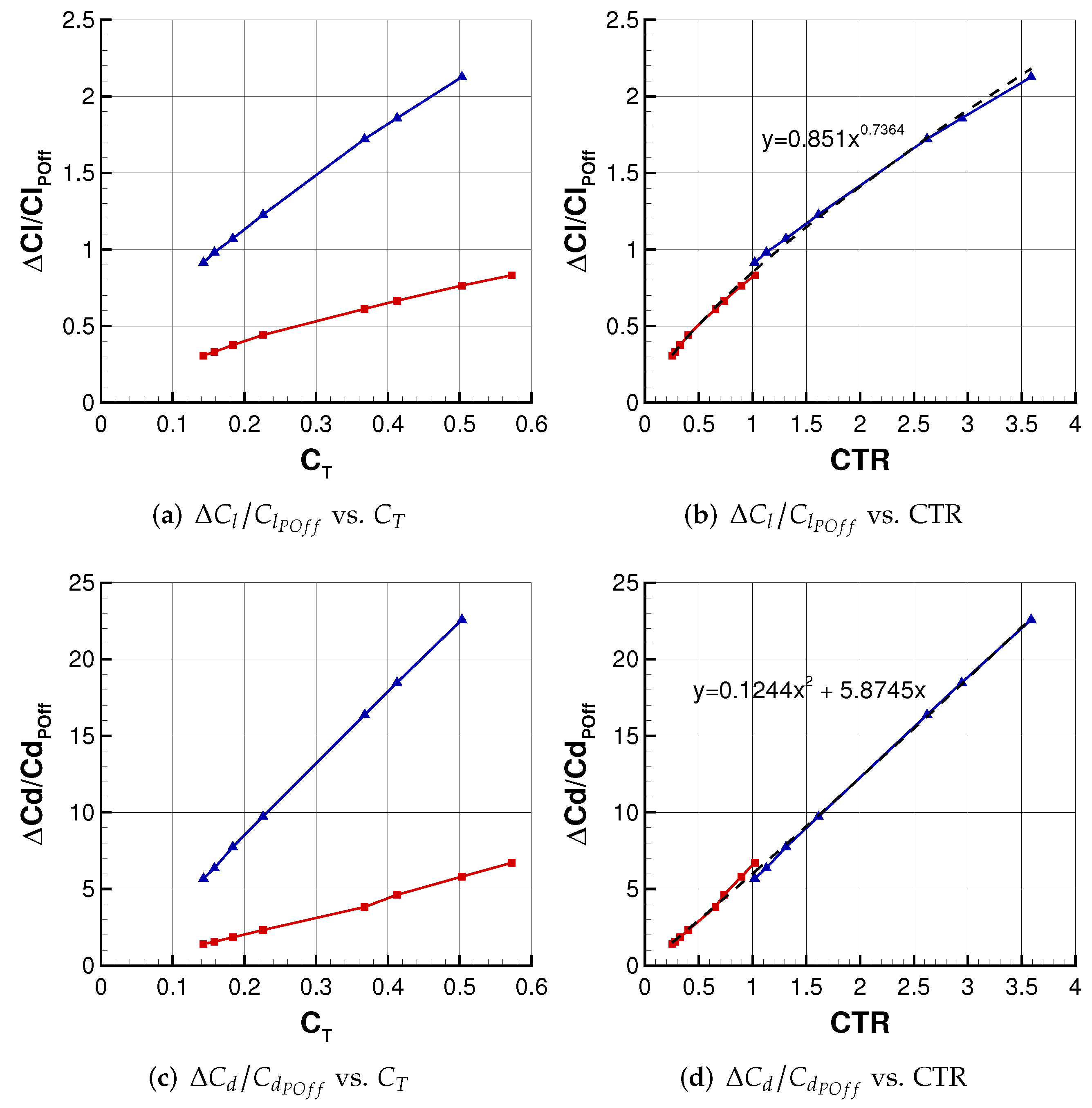
  ). The corresponding tendency lines are in dashed (
  ).
) and m/s ( ). The corresponding tendency lines are in dashed ( ).
).
) and m/s ( ). The corresponding tendency lines are in dashed ( ).
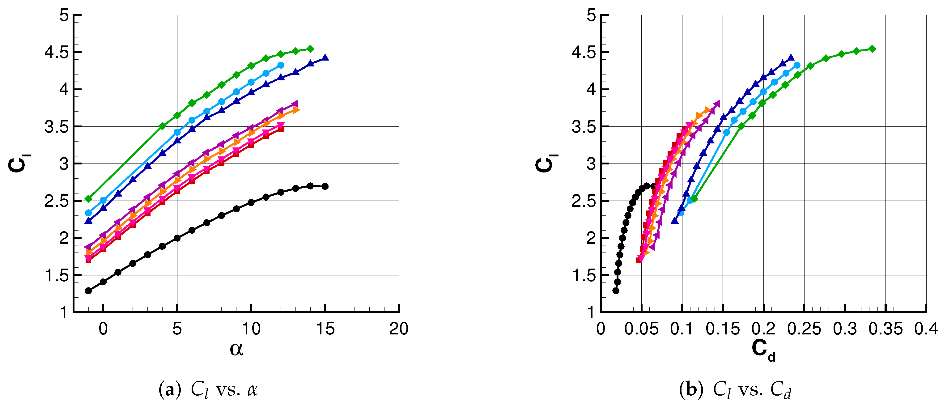
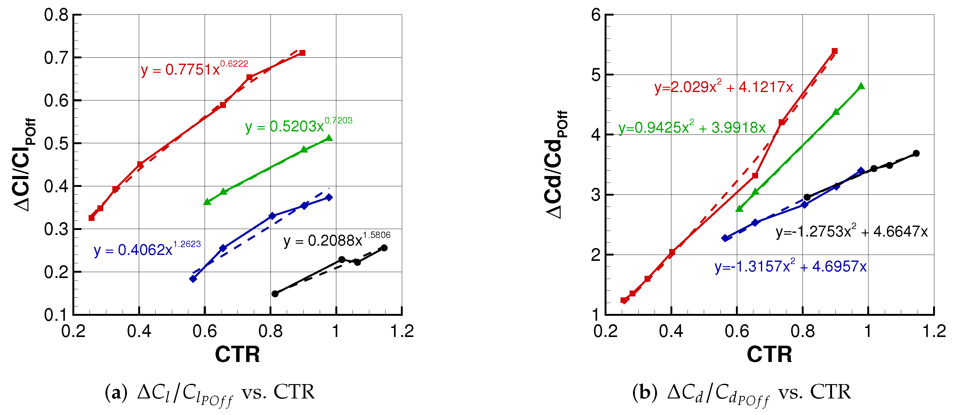
 ). Test case A1 ( ), B1 (
  ), C1 (
  ), D1 (
  ), E1 (
  ), F1 (
  ), and G1 (
  ).
). Test case A1 ( ), B1 ( ), C1 ( ), D1 ( ), E1 ( ), F1 ( ), and G1 ( ).
).
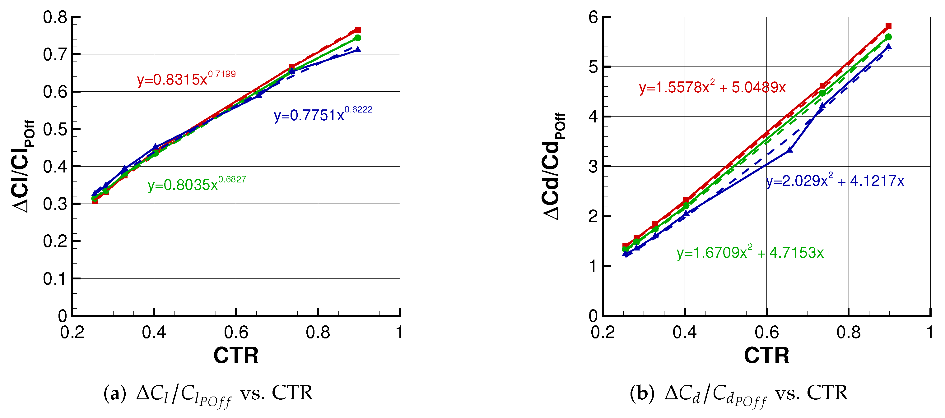
). Test case A1 ( ), B1 ( ), C1 ( ), D1 ( ), E1 ( ), F1 ( ), and G1 ( ). ), (
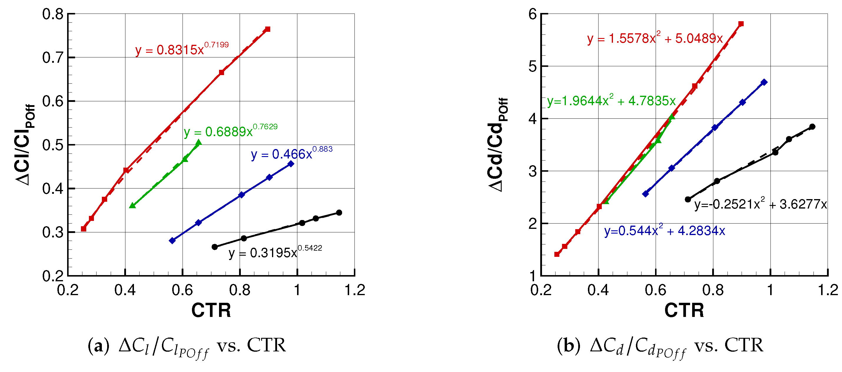
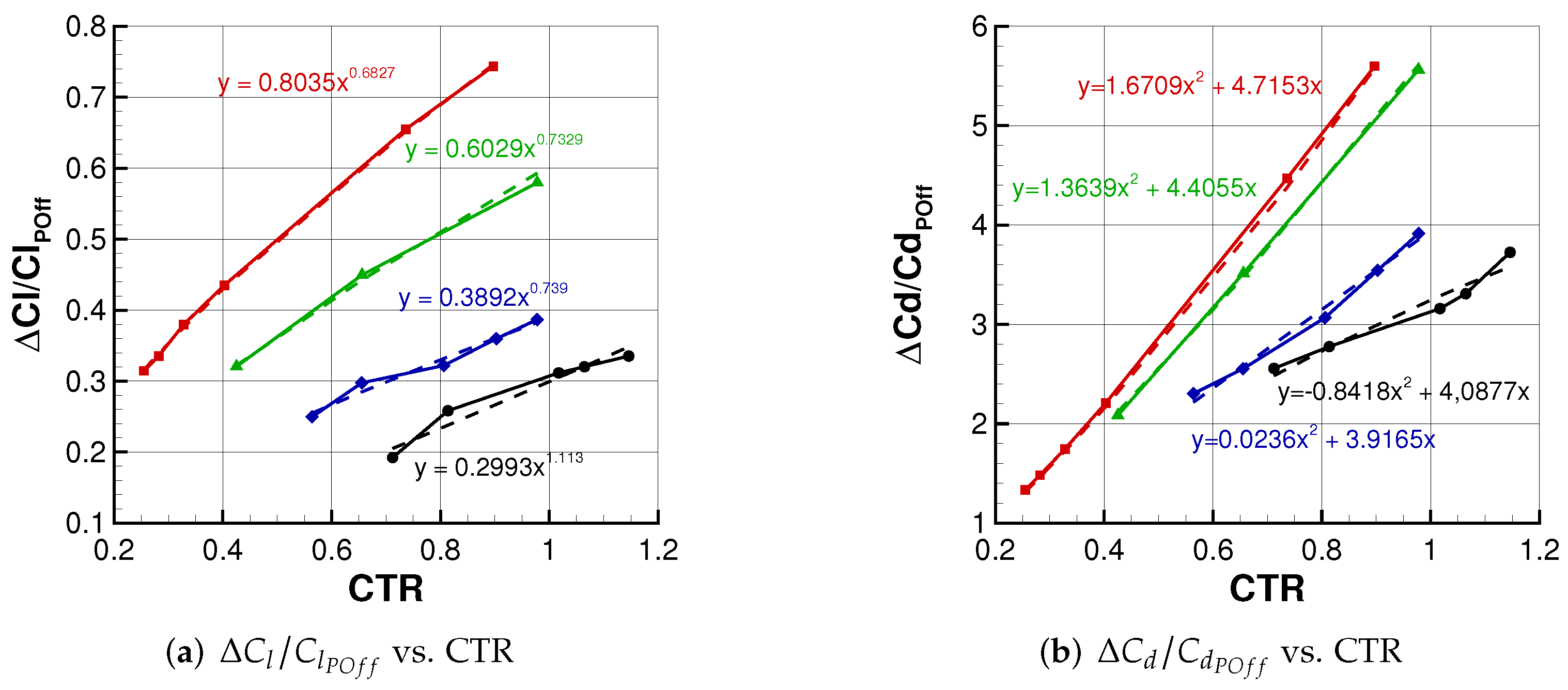
), (  ), (
), (  ), and ( ). In addition, their corresponding tendency lines are dashed.
), ( ), ( ), and ( ). In addition, their corresponding tendency lines are dashed.
), and ( ). In addition, their corresponding tendency lines are dashed.
), ( ), ( ), and ( ). In addition, their corresponding tendency lines are dashed. ), ( ), ( ), and ( ). In addition, their corresponding tendency lines are dashed.
), ( ), ( ), and ( ). In addition, their corresponding tendency lines are dashed.
), ( ), ( ), and ( ). In addition, their corresponding tendency lines are dashed. ), ( ), ( ), and ( ). In addition, their corresponding tendency lines are dashed.
), ( ), ( ), and ( ). In addition, their corresponding tendency lines are dashed.
), ( ), ( ), and ( ). In addition, their corresponding tendency lines are dashed. ), (
), (  ), and ( ) for . In addition, their corresponding tendency lines are dashed.
), ( ), and ( ) for . In addition, their corresponding tendency lines are dashed.
), and ( ) for . In addition, their corresponding tendency lines are dashed.
), ( ), and ( ) for . In addition, their corresponding tendency lines are dashed.
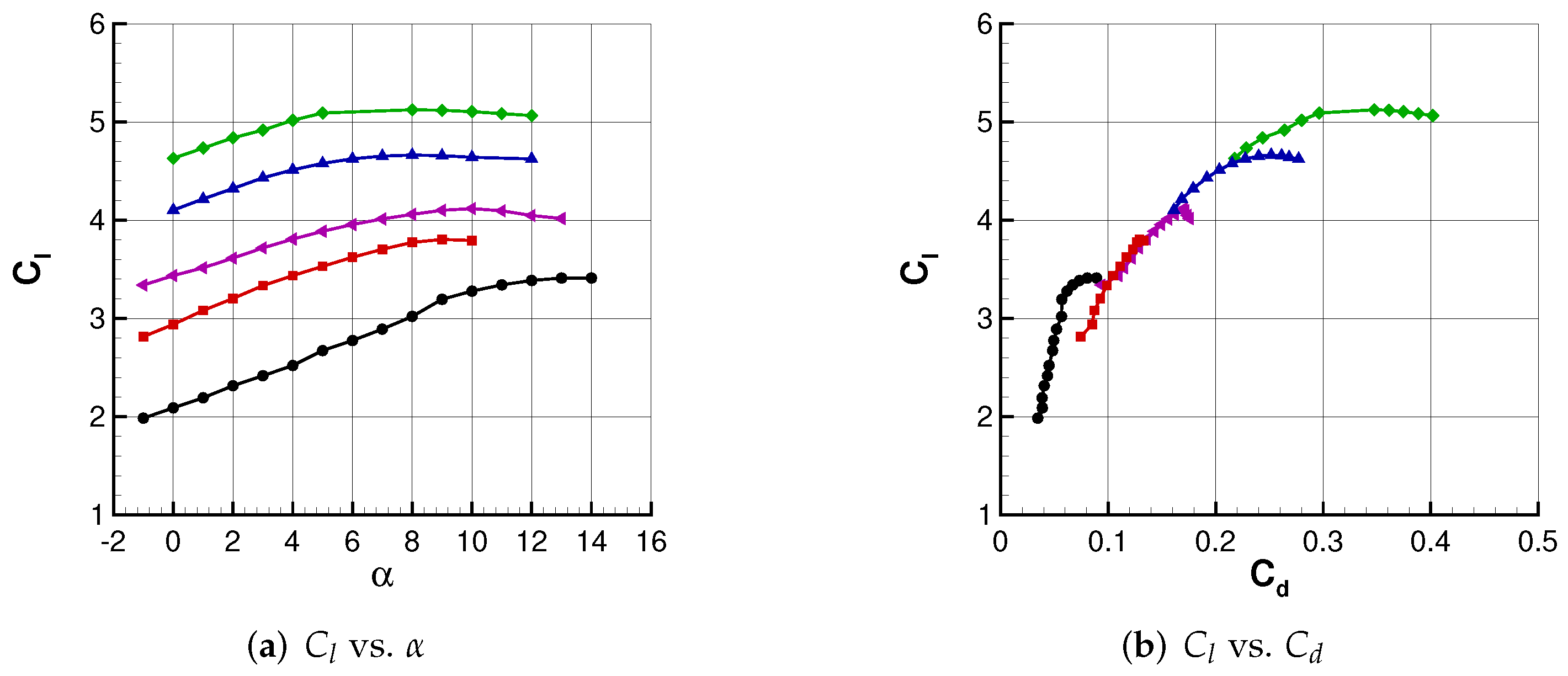
 ). Test case A1 ( ), D1 ( ), E1 ( ), and G1 ( ).
). Test case A1 ( ), D1 ( ), E1 ( ), and G1 ( ).
). Test case A1 ( ), D1 ( ), E1 ( ), and G1 ( ). ), ( ), and ( ). In addition, their corresponding tendency lines are dashed.
), ( ), and ( ). In addition, their corresponding tendency lines are dashed.
), ( ), and ( ). In addition, their corresponding tendency lines are dashed.

| Test 1 | Test 2 | Test 3 | Test 4 | |
|---|---|---|---|---|
| Number of propellers, NP | 8 | 12 | 16 | 20 |
| Propeller diameter [m] | 2.06 | 1.37 | 1.03 | 0.82 |
| Diameter–chord ratio, d/c | 0.802 | 0.533 | 0.401 | 0.319 |
| T [N] | CTR | Flap A | Flap B | ||
|---|---|---|---|---|---|
| Case A1 | 0.802 | 4745 | 0.2549 | ✓ | ✓ |
| Case B1 | 5250 | 0.2820 | ✓ | ✗ | |
| Case C1 | 6100 | 0.3277 | ✓ | ✗ | |
| Case D1 | 7500 | 0.4029 | ✓ | ✓ | |
| Case E1 | 12,200 | 0.6554 | ✓ | ✓ | |
| Case F1 | 13,700 | 0.7360 | ✓ | ✗ | |
| Case G1 | 16,700 | 0.8971 | ✓ | ✓ | |
| Case A2 | 0.533 | 3500 | 0.4251 | ✓ | ✗ |
| Case B2 | 5000 | 0.6073 | ✓ | ✗ | |
| Case C2 | 5400 | 0.6559 | ✓ | ✗ | |
| Case D2 | 7420 | 0.9012 | ✓ | ✗ | |
| Case E2 | 8050 | 0.9778 | ✓ | ✗ | |
| Case A3 | 0.401 | 2625 | 0.5641 | ✓ | ✗ |
| Case B3 | 3050 | 0.6554 | ✓ | ✗ | |
| Case C3 | 3750 | 0.8058 | ✓ | ✗ | |
| Case D3 | 4200 | 0.9025 | ✓ | ✗ | |
| Case E3 | 4550 | 0.9777 | ✓ | ✗ | |
| Case A4 | 0.319 | 2100 | 0.7120 | ✓ | ✗ |
| Case B4 | 2400 | 0.8137 | ✓ | ✗ | |
| Case C4 | 3000 | 1.0171 | ✓ | ✗ | |
| Case D4 | 3140 | 1.0646 | ✓ | ✗ | |
| Case E4 | 3380 | 1.1460 | ✓ | ✗ |
| 1.563 | 0.8813 | 0.2026 | 0.5203 | −0.473 | 6.53 | −1.135 | −7.744 | 8.4 | 0.9283 |
Publisher’s Note: MDPI stays neutral with regard to jurisdictional claims in published maps and institutional affiliations. |
© 2022 by the authors. Licensee MDPI, Basel, Switzerland. This article is an open access article distributed under the terms and conditions of the Creative Commons Attribution (CC BY) license (https://creativecommons.org/licenses/by/4.0/).
Share and Cite
de Rosa, D.; Morales Tirado, E.; Mingione, G. Parametric Investigation of a Distributed Propulsion System on a Regional Aircraft. Aerospace 2022, 9, 176. https://doi.org/10.3390/aerospace9040176
de Rosa D, Morales Tirado E, Mingione G. Parametric Investigation of a Distributed Propulsion System on a Regional Aircraft. Aerospace. 2022; 9(4):176. https://doi.org/10.3390/aerospace9040176
Chicago/Turabian Stylede Rosa, Donato, Elisa Morales Tirado, and Giuseppe Mingione. 2022. "Parametric Investigation of a Distributed Propulsion System on a Regional Aircraft" Aerospace 9, no. 4: 176. https://doi.org/10.3390/aerospace9040176