1. Introduction
According to the technical committee of the American Society for Testing and Materials, additive manufacturing (AM) is described as the process of material joining for the fabrication of three-dimensional (3D) parts. In this context, fused filament fabrication (FFF) is a 3D printing process based on thermoplastic polymers that uses a continuous filament to produce complex three-dimensional parts. This technique is also often confused with Fused Deposition Modelling (FDM), which is a trademark created by Stratasys co-founder Scott Crump in 1988 [
1].
In terms of materials, poly(ethylene terephthalate)-glycol (PETG) is one of the most used materials in 3D printing technology due to the chemical alkali resistance, transparency, gloss, low haze and good printability, among other benefits. Furthermore, with the correct print settings, it is possible to obtain excellent layer adhesion and very low shrinkage properties. At the same time, it is extremely strong, which allows one to print objects that can function at high temperatures or in food-safe applications and possess exceptional impact performance. All these advantages make this material suitable for both the food and medical industries [
2]. In the last case, for example, its rigid structure allows it to survive harsh sterilisation processes, making it a perfect material to be used in medical implants, as well as pharmaceutical packaging and medical devices [
3,
4]. However, adding carbon fibres reduces the risk of warpage even further, making the material more resistant and resilient, making it an excellent choice for automotive and other industrial applications [
5]. The addition of carbon fibres extends its field of application to the automotive and aeronautical sector, and others (such as prosthetics or adaptable parts of wheelchairs), because the material becomes more resistant and resilient, in addition to further decreasing the risk of warping [
6]. On the other hand, when reinforced with aramid fibres, the applications can be extended to the aeronautical and aerospace industries, where high resistance to friction and impact is expected [
7].
Kasmi et al. [
6], for example, developed studies involving PETG and PETG reinforced with carbon fibres and found, for both materials, that the best mechanical properties were obtained with raster orientations of 0°. Furthermore, a decrease in Young’s modulus and ultimate tensile strength was observed with increasing raster orientation. Therefore, it was possible to conclude that the mechanical properties of PETG with layers printed unidirectionally were significantly influenced by the raster orientation and shell presence. Similar conclusions were observed for PETG reinforced with continuous carbon fibres (CCF). For unidirectional layups at 0°, the Young’s modulus and ultimate tensile strength were significantly improved by the presence of the CCF composite, with values from 1.47 GPa and 30 MPa to 25 GPa (17 times higher) and 268 MPa (9 times higher), respectively. On the other hand, the elongation at break was around 1.9% for PETG-CCF specimens against 2.8% for the PETG ones, evidencing a more brittle behaviour. Similar studies were developed by Jiang et al. [
8] with commercially available carbon-fibre-filled (CFF) polymer composite filaments, and the results were compared to unfilled polymers from the same filament suppliers. Fibre length was less than 100 μm. In this case, the tensile modulus increased by 313.2% when CFF was added, for 0° printing orientation, while the tensile strength increased by around 48.2%. Kumar et al. [
9] used a Taguchi L9 approach to optimise the printing parameters in order to maximise the mechanical performance of carbon-fibre-reinforced PETG thermoplastics. The optimal tensile and flexural strength, as well as the hardness, were around 34.6 MPa, 36.5 MPa and 68.7 BHN, respectively, and the values obtained with a printing speed of 60 mm/s, infill density 80% and 200 μm layer height. The authors also noted that, while the print speed and infill density govern the tensile strength and hardness, flexural strength is influenced by layer height and infill density. In another study, Kumar et al. [
10] studied the infill density (25%, 50%, 75% and 100%) and the annealing treatment of PETG and PETG with 20 wt.% of carbon fibres (PETG+CF). It was observed that the best mechanical properties were obtained with annealed samples and 100% infill density, but compared to the annealed PETG, they were higher for annealed PETG+CF. For example, improvements of 21%, 25%, 23% and 18% were observed in terms of hardness, tensile, impact and flexural strength. Bhandari et al. [
11] studied the interlayer mechanical properties of PETG and PETG reinforced with short carbon fibres (SCF) and observed that the composites showed lower interlayer tensile strength than the neat PETG. This decrease was explained by the increase in the melt viscosity and consequent slower interlayer diffusion bonding. However, this decrease can be recovered by annealing when the temperature is higher than the glass transition temperature of the amorphous polymer (PETG). The postprocessing treatment, for example, increased the interlayer Young’s modulus (1.65 times compared to unannealed composite and 1.32 times compared to neat annealed PETG) and ductility of the printed composites. Ferreira et al. [
12] evaluated the benefits of adding short carbon fibres (20 wt.%) to PETG polymer and found benefits of 191.4% and 5.1% in terms of flexural modulus and strength, respectively, while tensile modulus improvements were only approximately 70.1%. However, a decrease of around 28.1% was observed in terms of tensile strength. Mansour et al. [
13], using similar materials (PETG and PETG with 20 wt.% of short carbon fibres), studied the compression properties and found a decrease in the compressive strain of 66% when the short carbon fibres (SCF) were added, while the modulus and hardness increased by around 30% and 27%, respectively. In terms of the loss factor and damping, those obtained from the cyclic compression and models tests dropped from 17.3% to 15.4% and 13.8% to 12.3%, respectively. Kromoser and Pachner [
14] developed a study on the load-bearing behaviour of knots made from different kinds of polymer-based printing materials, including PETG, and the results showed that PACF (a carbon-fibre-infused polyamide-based material) had the best compressive mechanical properties and a brittle failure behaviour. A similar behaviour was observed for PETG but for lower compressive values (2–3 times smaller). Sörensen et al. [
15] used the FFF process to manufacture a tooling to obtain a small series of sheet metal parts in combination with the rubber pad forming process for the automotive sector and, for this purpose, a variety of common AM polymeric materials (PETG, PLA and ABS) were compared in compression tests. Both PETG and PLA were able to fulfil the proposed performance (loading capacity), but in this study, PLA was selected due to its bio-based structure and its industrial composting possibilities. Hsueh et al. [
16] compared the compression properties of PLA and PETG specimens at different printing temperatures and speeds. They found that the values of the compression properties increased with the increasing printing temperature due to the decrease in the contact stress at the line and line contacts. It was also observed that there was a minimal effect on the compression properties of PETG with respect to the printing speed. However, the compression properties of PLA were higher than those of PETG, similar to their tensile properties. Mercado-Colmenero et al. [
17] developed a numerical and experimental study on PETG produced by the FDM technology in order to obtain its mechanical characterisation under uniaxial compression loads. They found that the specimens manufactured in the X, Y and Z directions had a completely linear behaviour until reaching the elastic limit, the point from which the plasticisation process begins until the final fracture. However, different structural failures were observed. For the specimens produced along the Z direction, fracture was brittle due to the delamination of adjacent layers and breakage of the filaments, while, along the X and Y directions, they presented permanent plastic deformations due to the lower strength compared to the specimens manufactured in Z. Finally, Patterson et al. [
18] studied the IZOD impact properties of different materials and observed, for example, that polylactic acid (PLA), PLA + wood fibre (WPLA), PLA + chopped carbon fibre (CFPLA) and PLA + aluminium powder (AlPLA) showed little or no local plastic deformation, while some plastic deformation on the fracture surface (mainly localised and not too deep into the part) was noted for acrylonitrile butadiene styrene (ABS), high-temperature PLA (HTPLA) and high-impact polystyrene (HIPS). Finally, polycarbonate (PC), nylon (a synthetic polyamide) and polyethylene terephthalateþglycol (PETG) showed significant plastic deformation, including large and deep scars on the part, stretching and layer pullout.
Therefore, from the literature [
2,
3,
4,
5,
6,
7], it is evident that PETG and PETG-based composites have applications in many industries due to their resistance to heat, impact and solvents. In terms of compressive properties, the focus of the present study, the literature is not abundant on this topic and what exists is not enough to establish a consolidated knowledge base [
13,
14,
15,
16,
17], because most of the available studies focus essentially on the tensile mode. On the other hand, as consequence of the inherent viscoelasticity of the matrix phase, polymer composites are prone to creep and stress relaxation, making it a great challenge when used in long-term applications. However, in terms of creep and stress relaxation behaviour, these subjects are totally absent in the open literature for PETG and PETG-based composites, limiting their use in many applications due to lack of knowledge. In this context, the novelty of this study is related to the effect of fibre type on the compression properties of PETG-based composites, to consolidate knowledge, but essentially at the level of creep and stress relaxation behaviour due to the absence of studies in this domain. For this purpose, an experimental study was developed to characterise the compressive properties of PETG and PETG reinforced with carbon and aramid fibres, as well as the stress relaxation and creep behaviour of these materials.
2. Materials and Methods
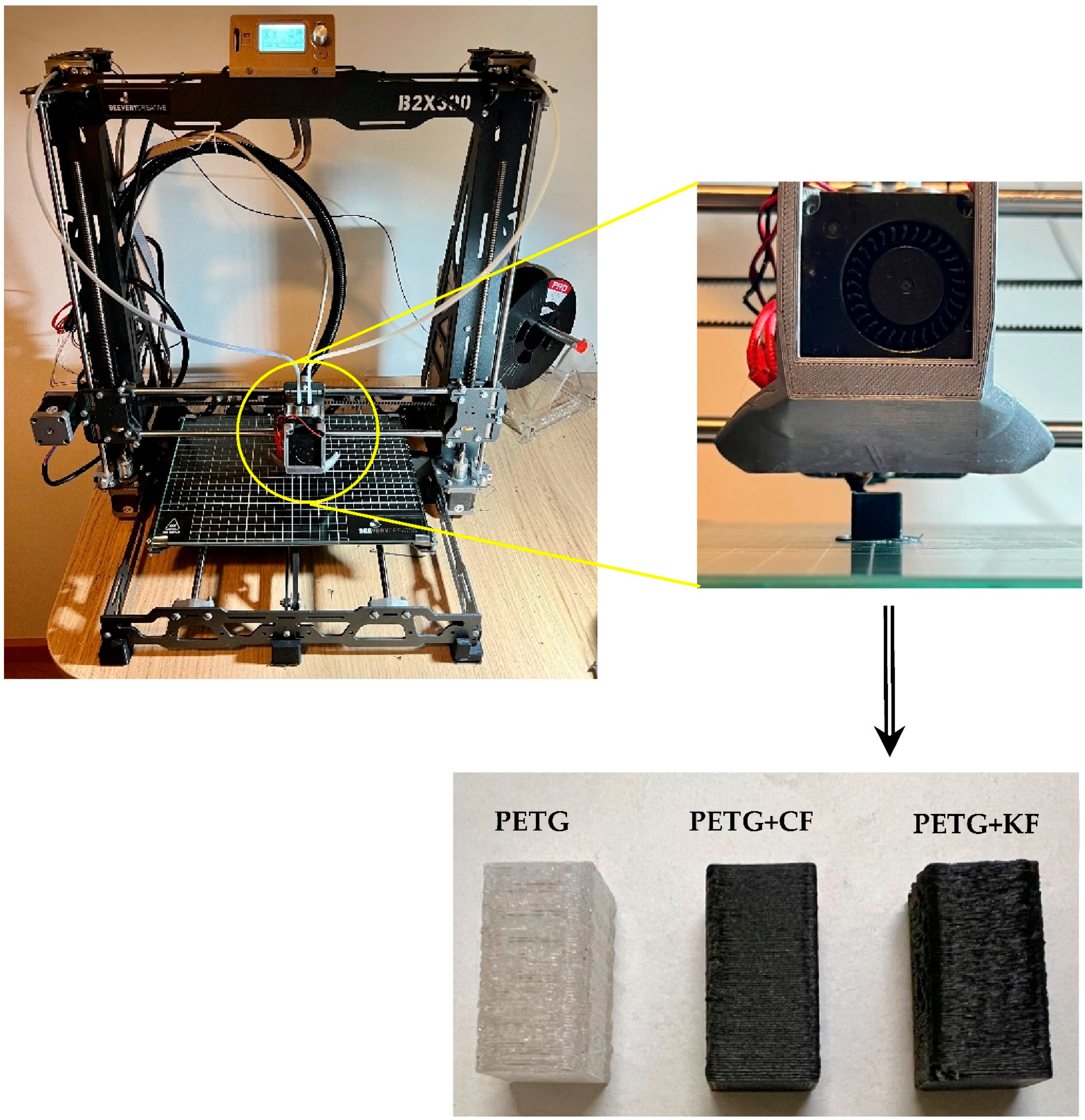
The B2X300 printer was used to extrude the initial 1.75-mm-diameter filament through a 0.6-mm-diameter nozzle. The extruded filament was placed on a platform heated by a print head in a user-defined pattern to achieve the desired flat shape. Once a particular layer was finished, the print head was raised and continued to deposit the next layer. Using this equipment and methodology (see
Figure 1), specimens with dimensions of 12.7 × 12.7 × 25.4 mm
3 were printed, values that are recommended by the ASTM D695-15 standard [
19].
In terms of materials, poly(ethylene terephthalate)-glycol (PETG) is one of the most used materials in 3D printing technology due to its chemical alkali resistance, transparency, gloss, low haze and good printability, among other benefits. However, the addition of carbon fibres (CF) further expands its field of application because the composite becomes more resistant and resilient, as well as significantly reducing the risk of warping. In this case, it becomes an excellent choice for automotive, aeronautical and aerospace applications, besides other industrial applications. On the other hand, when reinforced with aramid fibres (KF), applications can be extended to components where high resistance to friction and impact is expected. Therefore, given the benefits reported for these materials, PETG, PETG + CF and PETG + KF were the filaments selected to obtain the specimens used in this study. While PETG composites containing fibres were supplied by Nanovia (Louargat, France), neat PETG was supplied by FilTech (Baesweiler, Germany). Different printing parameters were used, and
Table 1 shows those that maximised the mechanical properties of these materials. For this purpose, a study was previously carried out. The criterion of maximum mechanical performance was adopted, because, in any structural application, we expect, in general, to maximise the mechanical properties.
The deposition angle direction was [0/45/−45/90/90/−45/45/0], which means that the first layer was printed in a unidirectional pattern at an angle of 0° from the horizontal. The second layer was rotated 45° away from the horizontal, the third rotated −45° and the fourth rotated 90°, and this sequence continued as a mirror until the code was completed. This is a quasi-isotropic sequence and was selected because the extensional stiffness of the laminate was practically the same in each in-plane direction.
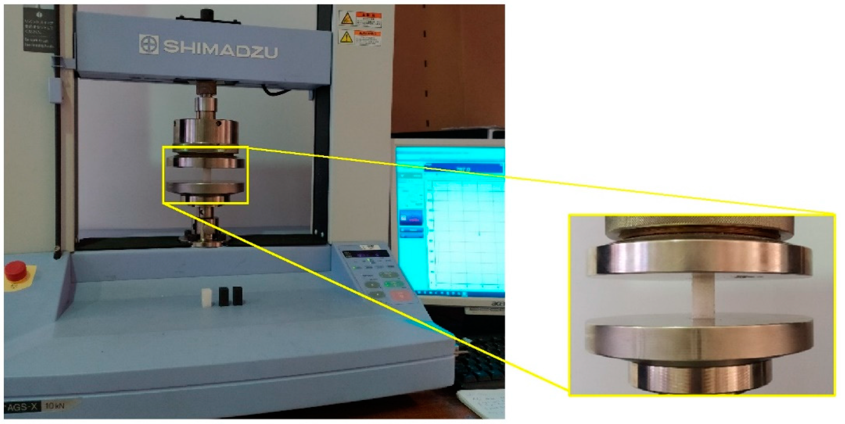
Finally, compressive tests were carried out in accordance with the ASTM D695-15 standard [
19] in a Shimadzu universal testing machine (Duisburg, Germany), model Autograph AGS-X, equipped with a 10 kN load cell (
Figure 2). For each condition, 5 specimens were tested at room temperature with a displacement rate of 1.3 mm/min. Compressive yield strength was calculated by dividing the yield compressive load carried by the cross-sectional area of the specimen. The compressive modulus was calculated by drawing a tangent to the initial linear portion of the load deformation curve.
Stress relaxation and creep tests were also carried out in the same machine (Shimadzu, model Autograph AG-X), at room temperature, and using specimens with geometry similar to those used on the compressive tests. For the first tests, a fixed strain was applied (correspondent to 75%, 50% and 25% of the yield compressive stress for all configurations) and the stress recorded during the loading time. In terms of creep tests, a fixed stress was applied (correspondent to 75%, 50% and 25% of the yield compressive stress for all configurations) and the displacement recorded during the loading time. These values were selected to guarantee that all tests were performed in the elastic regime of all configurations analysed.
3. Results and Discussion
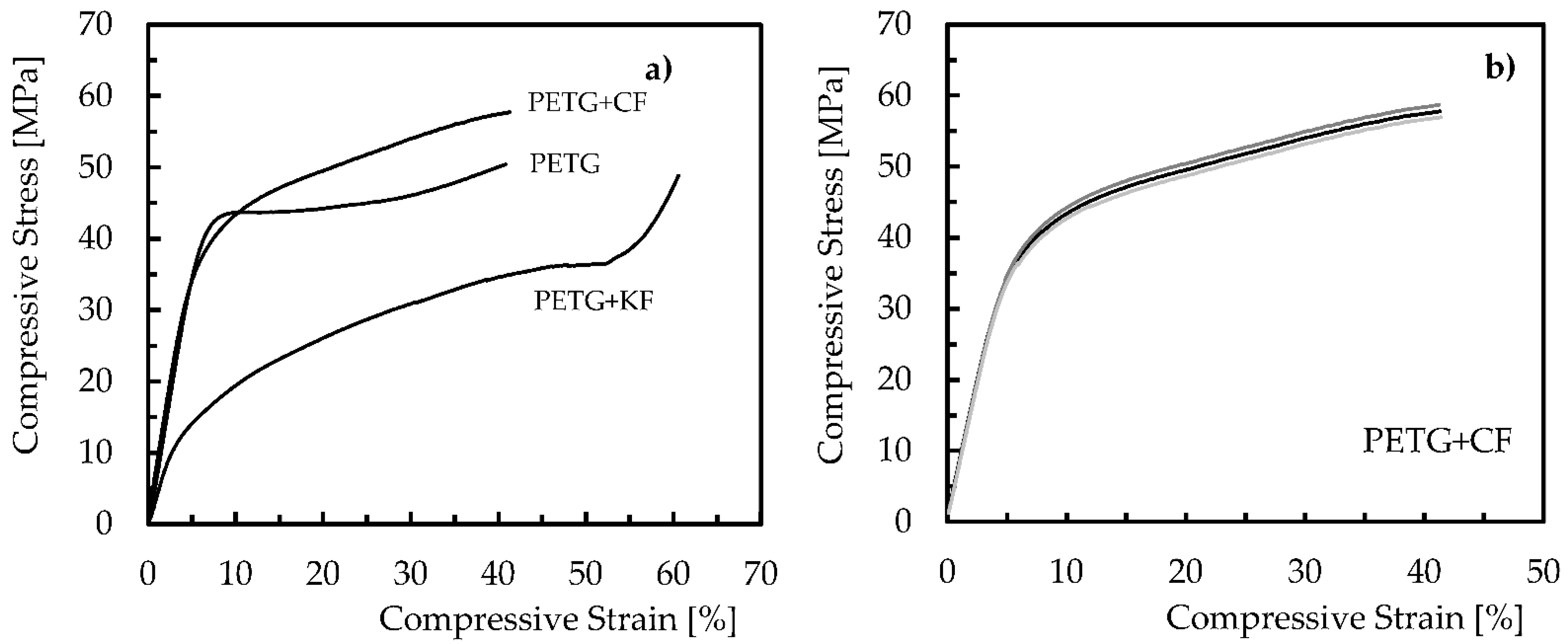
Experimental tests were performed to obtain the compressive properties. In this context,
Figure 3 shows the load–displacement curves obtained for each condition, which are representative of the others.
Figure 3b shows the repeatability of the curves for PETG with carbon fibres, evidencing the low dispersion represented in
Table 2. The low dispersion observed extends to the other materials analysed.
For all materials, a linear region is observed, in which the material deforms elastically and returns to its original length when the stress is removed. This region terminates when the yield point is reached, and the material starts to have a plastic behaviour. Under these conditions, it no longer regains its original length when the load is removed. However, depending on the material, the linear region presents different extensions, denoting that there are materials with longer elastic regimes than others. Therefore, different compressive properties are expected, which are summarised in terms of mean values and respective standard deviations in
Table 2.
Regarding the yield compressive strength, the highest value was obtained for the neat PETG, and when the carbon and Kevlar fibres were added, a decrease of around 9.9% and 68.7% was found, respectively. A similar behaviour is also observed for the compressive displacement, where an average value of 5.4 mm is obtained for pure PETG, but, in this case, the decrease is around 20.4% and 46.3%, respectively. Concerning the compressive modulus, and when compared to the neat PETG (680.8 MPa), there is an increase of 12.4% when carbon fibres are added to the PETG matrix and a decrease of 39.6% for Kevlar fibres. These results agree with the studies developed by Mansour et al. [
13], where, for similar materials (PETG and PETG with 20 wt.% of short carbon fibres), they found a decrease in the compressive strain and an increase in modulus when carbon fibres were added. In terms of compressive strength, the decrease that is observed is in line with the studies developed by Mahesh et al. [
20], where the addition of SCF to PETG composites (5 and 10 wt.% of SCF) promoted decreases between 3% and 12%. According to the authors, most of the load is supported by the matrix, which means poor matrix–fibre adhesion and load transfer at these points. Furthermore, these authors also mention that excessive shear stresses acting on the layer interface and fibre–matrix interface, as well as the air gaps between the adjacent printed layers, contribute to this decrease [
20]. However, the literature reports good fibre–matrix adhesion for glass and carbon fibres, while Kevlar fibres are recognised for establishing weak fibre–matrix adhesion [
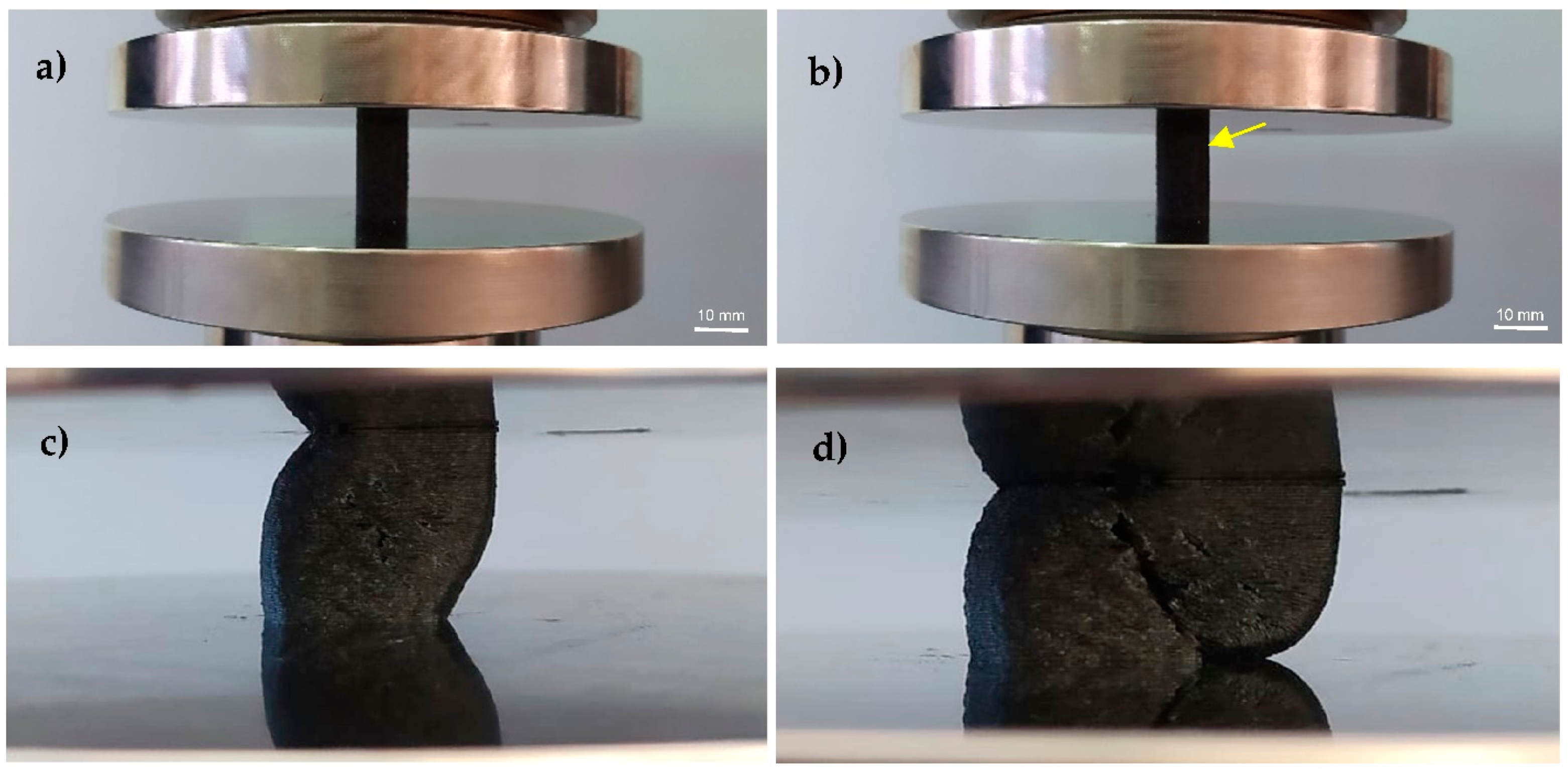
21]. In this context, the poor results obtained with Kevlar fibres can be explained by the weak interfaces between the Kevlar fibres and the PETG matrix, while, for the PETG composite reinforced with carbon fibres, it can also be explained by the damage mechanisms observed in
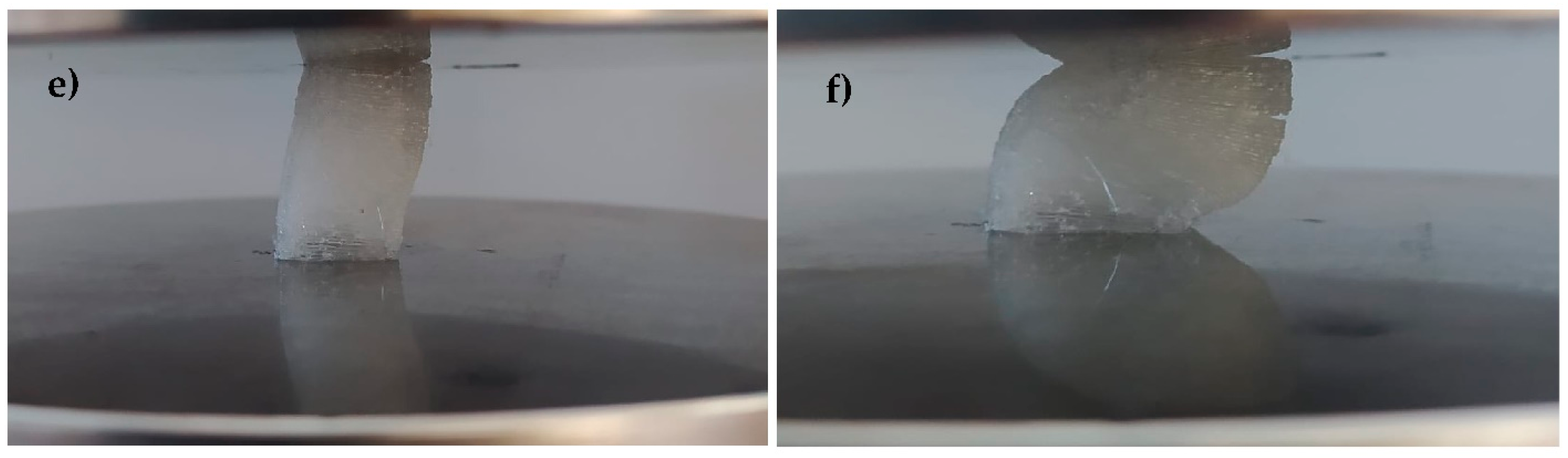
Figure 4. This figure shows details of the specimens during the compressive tests for PETG and the PETG composite reinforced with carbon fibres (PETG+CF). In terms of PETG+CF, for example, in the linear region, the specimen geometry maintains its shape (
Figure 4a), and the compressive load closes the intra- and inter-layer porosities generally exhibited within the print beads and adjacent layers of the print [
22]. Subsequently, this phenomenon promotes internal instability that leads to the minor buckling of the samples (buckling initiated at the arrowhead in
Figure 4b), which, when increasing, allows the adjacent fibre–matrix and matrix–matrix interfaces buckled within the specimen to bend in a similar way (see
Figure 4c) and, consequently, shear stresses/strains arise [
22]. Continuing to apply the load, a significant shear deformation is observed with the consequent sudden occurrence of a dominant crack between layers (see
Figure 4d). In terms of neat PETG,
Figure 4e,f report a similar behaviour, but instead of a dominant crack, there are several small cracks between layers.
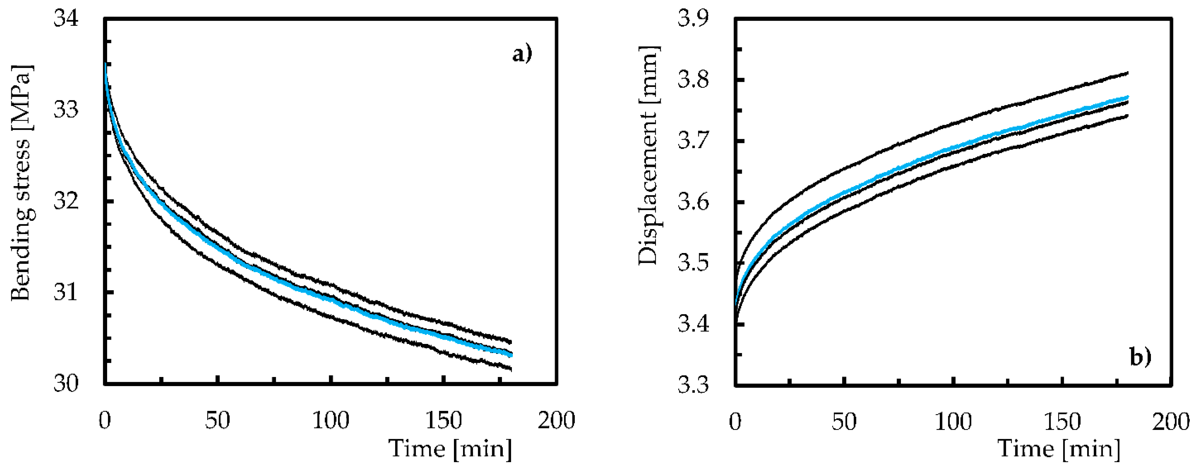
Regarding the creep and stress relaxation behaviour, the results obtained from these tests are shown in
Figure 5 for neat PETG. Three curves obtained from the experimental tests and the respective average curve (blue colour) are shown, which, despite representing the observed behaviour for 50% of the yield compressive stress, are also representative of the tests performed for the other stress levels.
It is possible to notice a consistent behaviour and without significant dispersion, which justifies the low scattering presented in the figures below and the respective discussion. Therefore,
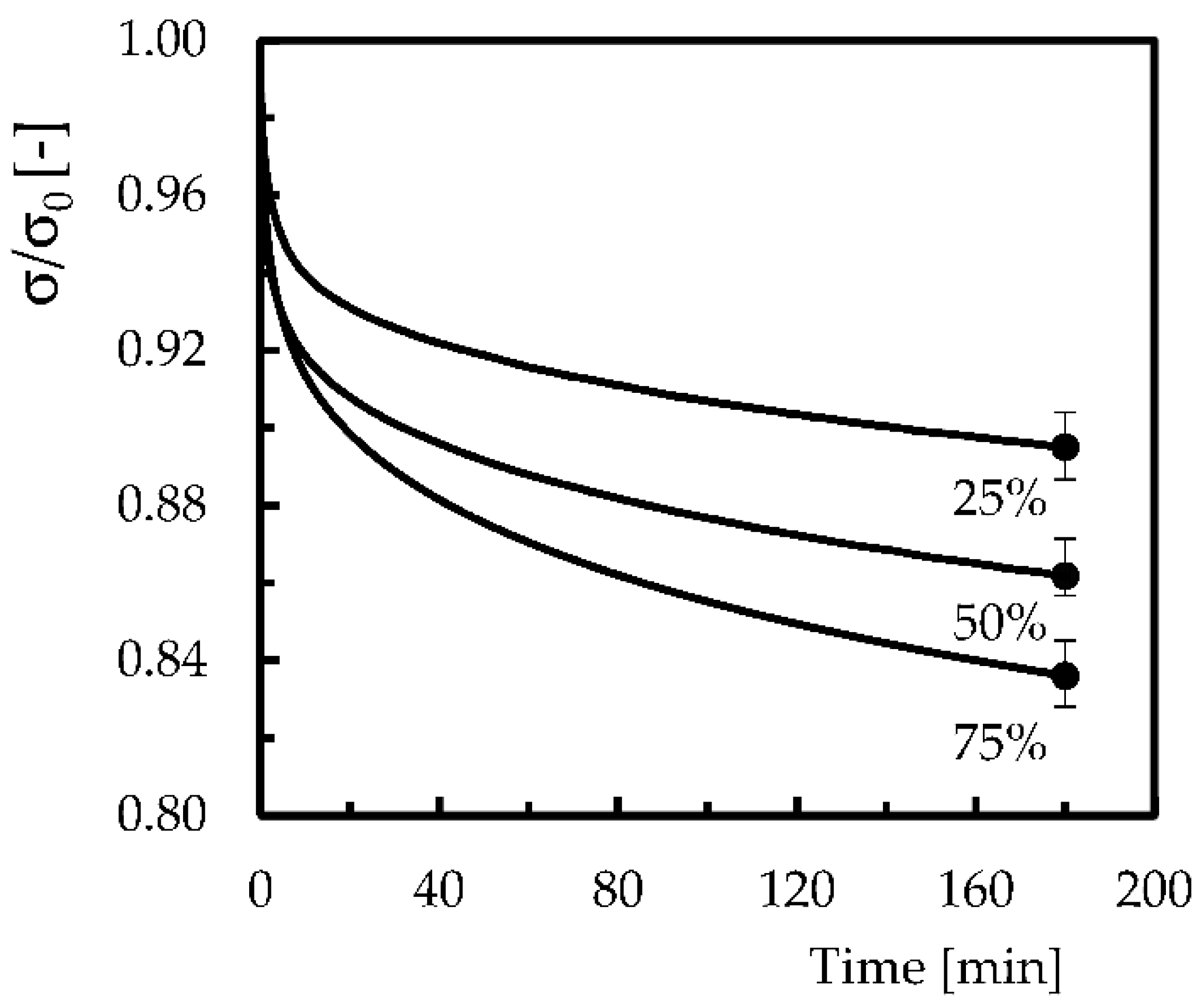
Figure 6 plots the average compressive stress versus time obtained for a fixed strain correspondent to 75%, 50% and 25% of the yield compressive stress, where σ is the compressive stress at any given moment of the test and σ
0 is the initial compressive stress. The final bands represent the maximum and minimum values obtained for each condition analysed. In this case, the compressive stress decreases with time for all analysed strains, but this tendency becomes more pronounced with the increase in the strain for which the experiment is carried out. For example, for a constant displacement corresponding to 25% of the yield compressive stress, the compressive stress continuously decreases over the analysed time, reaching, for example, values around 10.5% lower after 10,800 s (3 h). However, this difference increases to 13.8% and 16.4% for compressive displacements correspondent to 50% and 75% of the yield compressive stress, respectively. In fact, after some time, it would be expected that this reduction would tend towards a constant value, but, in the present work, this was not achieved because short-term tests were considered. According to the open literature, these tests are an easy, fast and reliable method to predict long-term behaviour [
23,
24,
25]. On the other hand, it is also reported that an initial stage occurs in which the stress decreases considerably in relation to the remaining time [
26,
27,
28], and this evidence is also observed in the present study for all compressive strains analysed.
The bibliography justifies the typical decreases observed in plastics during stress relaxation tests due to physical and/or chemical phenomena. In the first case, molecular rearrangements that require little formation or rupture of primary bonds explain the observed decrease, while, from a chemical point of view, it is justified by the chain scission, crosslink scission or crosslink formation [
29,
30,
31], both expected in this study. Furthermore, any decohesion that may occur between the printed interface layers or the air gaps between adjacent printed layers can also contribute to the observed decrease. Regarding the displacement effect (correspondent to 25%, 50% and 75% of the yield compressive stress), it is possible to observe that its increase promotes higher stress relaxation due to a change in the mechanisms mentioned above. For example, at lower displacement levels, stress relaxation is mainly induced by the molecular rearrangements and/or chain scission, while, for higher displacement levels, it is due to damage and its propagation. This is line with the studies developed by Mirzae et al. [
32], where these authors also observed that increasing the strain level promotes more stress relaxation.
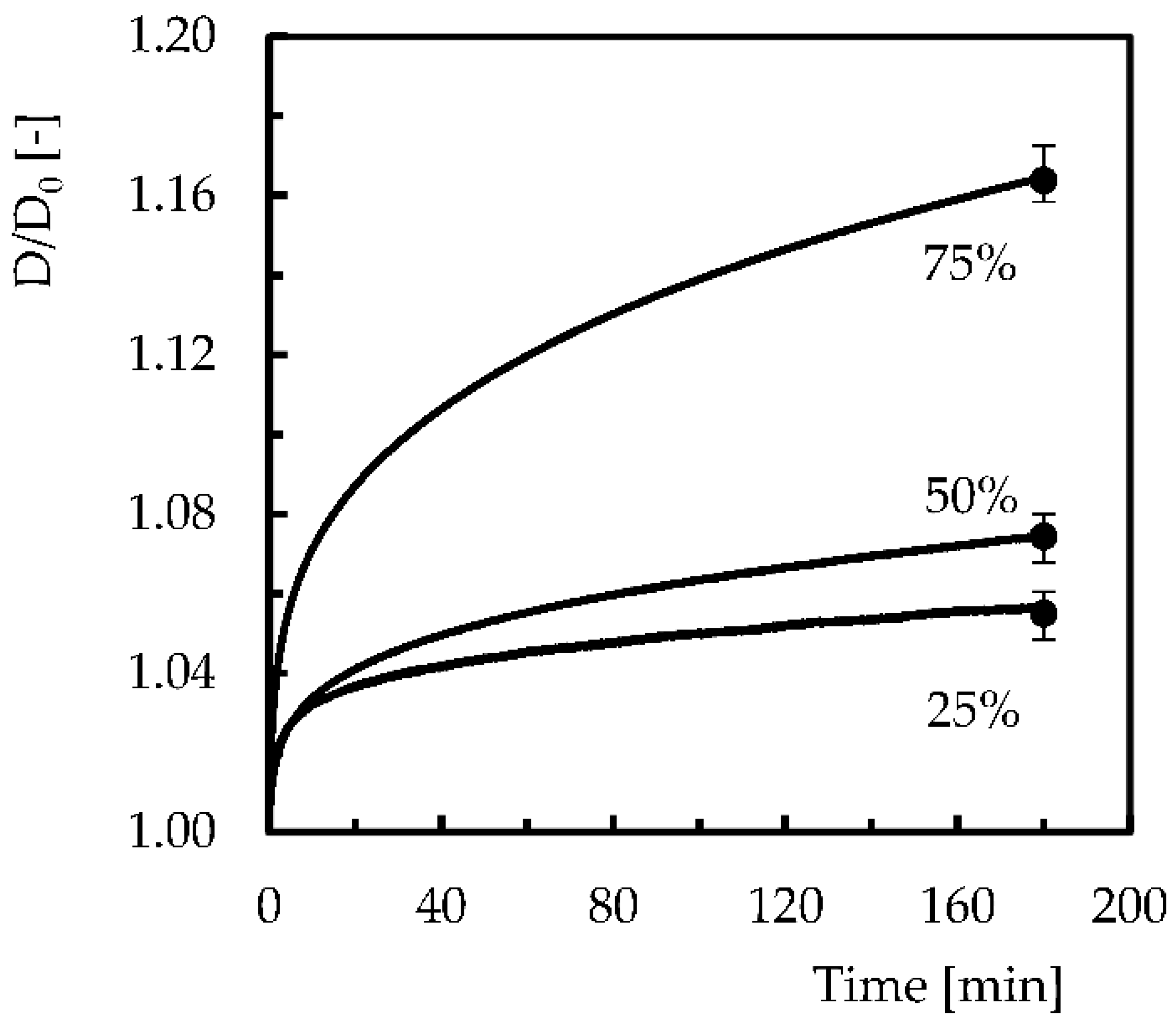
The creep behaviour observed for the different compressive stress levels is shown in
Figure 7, where the displacement is the value obtained at any instant of the test (D) divided by its initial value (D
0). Once again, the final bands represent the maximum and minimum values obtained for each condition analysed. It can be noted that all curves present an instantaneous displacement, which is dependent on the compressible stress level, followed by the primary and secondary stage. This is a typical behaviour of creep curves, where the third stage is only expected for higher stress values or longer times. In quantitative terms, for example, after 180 min, the compressive strain increases by 5.5%, 7.4% and 16.4% for compressive stresses of 25%, 50% and 75% of the yield compressive stress. These results prove that the creep phenomenon in polymers occurs even at room temperature and for stresses below the ultimate strength, which is explained by the molecular motion in the backbone polymer arrangement [
33,
34,
35,
36].
It is also possible to notice that the stress levels significantly influence the creep displacement of the material. This behaviour agrees with what has been described for stress relaxation and is also justified by the change in the previously reported mechanisms. In this case, at lower stress levels, creep is mainly induced by molecular movements, while at higher stress levels, creep is dominated by damage and its propagation. For the highest stress levels, the load transfer on the interface regions is significantly affected and, inclusively, some debonding is expected [
22]. However, as displacement is held constant in stress relaxation, any mechanism reported above will have lower severity than in creep, because the deflection is always increasing [
22].
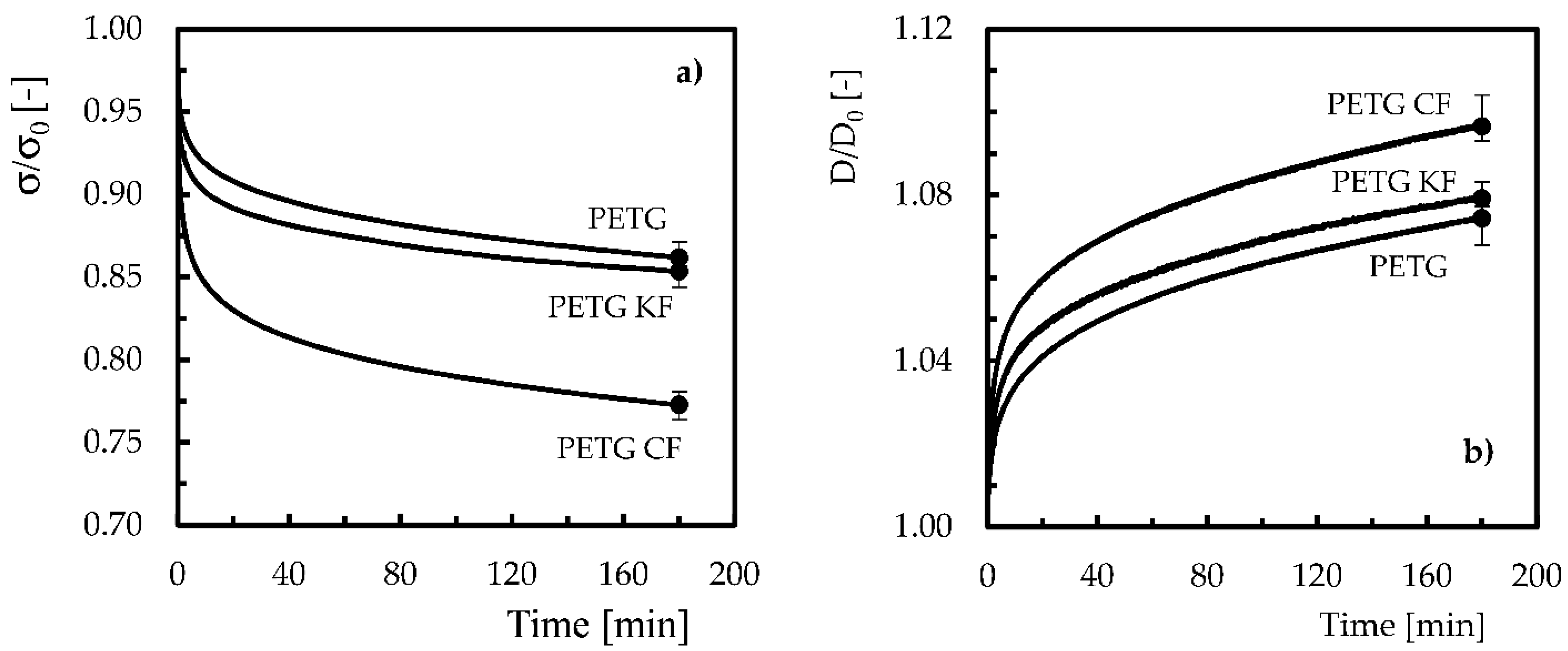
In terms of PETG-based composites, stress relaxation and creep behaviour are compared in
Figure 8 for 50% of the yield compressive stress. In this figure, the type of fibres used is also compared.
Concerning the stress relaxation behaviour (
Figure 8a), the neat polymer is, of all materials, the one with the lowest relaxation. For example, compared to the initial compressive stress, after 180 min, the neat PETG showed a decrease of around 13.8%, while, for PETG + KF and PETG + CF, this value was around 14.7% and 22.7% less than that obtained for the neat polymer, respectively. On the other hand, the creep behaviour (
Figure 8b) showed a similar trend, where the compressive displacement after 180 min increased by around 7.4% compared to the initial value for neat PETG. However, when Kevlar and carbon fibres were added to the polymer, the compressive displacements after 180 min were, respectively, 7.9% and 9.7% higher than the value obtained for the neat polymer. In terms of polymers, and as reported above, while stress relaxation occurs due to physical and/or chemical phenomena, molecular motion in the backbone polymer arrangement explains the creep behaviour. However, when fibres are used to reinforce polymers, they hinder the molecular flow in the matrix and, consequently, delay the relaxation process [
37]. In this context, the interface properties play a relevant role because relaxation is due to the breaking of bonds and their propagation. In terms of creep behaviour, the fibre–matrix interface is also very important because the bonds’ breakage and their propagation control the creep displacement [
34,
38]. Therefore, the creep process is delayed because both elastic deformation and viscous flow are retarded by the presence of fibres. Nevertheless, reducing the size of the reinforcements and an increase in their weight content promotes aggregation and the consequent loss of mechanical properties [
39]. In addition, Mahesh et al. [
20], when using a similar filament, found that most of the load was supported by the matrix, revealing, in this case, poor matrix–fibre adhesion. In such contexts, these authors reported that the excessive shear stresses acting on the layer interface and fibre–matrix interface, accompanied by the air gaps between printed layers, justified the lower compressive strength of the composites compared to neat PETG. In fact, the inter-layer adhesion proves to be determinant regarding thermal and mechanical properties, including tensile, fatigue, toughness and creep [
40,
41,
42]. Voids promote low inter-layer strength and are sites of crack growth due to reduced inter-layer adhesion [
42]. Furthermore, voids created during printing processes can reduce the material density and cause lower thermal, mechanical and conductive properties [
42,
43]. Therefore, all these facts reported in the open literature explain the higher compressive displacement, stress relaxation and creep behaviour observed in composites compared to neat PETG.
4. Conclusions
Poly(ethylene terephthalate)-glycol (PETG) is a thermoplastic widely used in 3D printing due to its excellent layer adhesion, very low shrinkage, good mechanical strength and high service temperature. These advantages make it suitable for several applications, but when reinforced with fibres, it becomes even more attractive. In previous studies, the characterisation of neat PETG and PETG-based composites essentially focuses on the tensile mode; however, the compression behaviour should be considered early in the design phase because it is also a very common loading mode. In this context, the compressive properties of PETG and PETG reinforced with carbon and aramid fibres were analysed in terms of static properties as well as creep and stress relaxation behaviour.
From the static characterisation, it was possible to conclude that, in relation to the neat PETG, the yield compressive strength decreased for both composites, with the largest drop observed for the PETG reinforced with Kevlar fibres (around 68.7% lower). Similar behaviour was observed for the compressive strain for PETG reinforced with carbon and Kevlar, where there was a decrease of 20.4% and 46.3%, respectively. Nevertheless, the highest compressive modulus was observed for PETG reinforced with carbon fibres (increase of 12.4%), while the lowest modulus was observed for PETG with Kevlar fibres (decrease of 39.6%).
In terms of stress relaxation behaviour, it was possible to observe, for the neat PETG, as expected, a decrease in compressive stresses over time, but more expressive for higher strain levels. Compared to the initial compressive stress, after 180 min, the neat PETG showed a decrease of 13.8%, while, for PETG reinforced with Kevlar and carbon fibres, decreases of around 14.7% and 22.7%, respectively, were observed. On the other hand, the creep response promoted higher compressive displacements, which were shown to be dependent on the level of compressive stresses. Thus, the compressive displacements after 180 min were, for PETG reinforced with Kevlar and carbon fibres, respectively, 7.9% and 9.7% higher, than the value obtained for the neat PETG. However, in the design of components subject to the compression mode, contrary to what is typical for the tensile mode, when fibres are added to PETG, higher values of stress relaxation and compressive displacement are observed.


