1. Introduction
The need to reduce greenhouse gas emissions and thus halt the rise in Earth’s temperature—which is now being felt very acutely through very high temperatures, rapid changes in weather, droughts, and the melting of glaciers—has arisen. Such extremely high temperatures do not allow smaller planes to fly (in 2018 and 2017 in Phoenix this situation occurred). Reducing CO
2 emissions will reduce the pollution of the air and oceans. It should not be forgotten that the extraction of fossil fuels alone leads to the destruction of the environment and fauna. Another very serious problem is the depletion of fossil fuel sources. In its Statistical Review of World Energy, BP predicted that in as little as 50 years they may be depleted [
1]. For this reason, it is necessary to significantly reduce the demand for fossil fuels.
Aviation is not the biggest CO
2 emitter in the transport sector. However, it is responsible for other important pollutants and noise, which means that the decarbonisation of aviation and making it more eco-friendly is one of the important goals of today’s world. According to data given by the Environmental and Energy Study Institution and the Environmental Report issued by the ICAO, aviation is responsible for 2.4% of total global carbon dioxide emissions (for the transport sector, aircraft produced 11.6% of CO
2). Furthermore, emissions of pollutants other than CO
2 from aircrafts have a very harmful effect on climate. Aviation is also responsible for around 1.6% of global high-altitude nitrogen oxide emissions of nitrogen oxides (NOx), which could lead to the production of ozone and the formation of water vapour causing contrails, which spread into high-level thin cirrus clouds and act as a blanket for thermal infrared radiation [
2,
3].
These issues have been covered in several international documents, recently in EU’s Flightpath2050 and European Green Deal, which set very ambitious emissions and external noise reduction targets. The former document assumes that in 2050 the pollution generated by aviation should be reduced by 90% for NOx, 75% for CO
2, and generate 65% less noise than in 2000 [
4]. In the latter, the following goals were pointed out: to reduce greenhouse gas emissions by a minimum of 55% by 2030 and to make Europe the first climate neutral continent in the world in 2050 [
5]. According to these documents, aviation is facing very ambitious pollution reduction targets, which could be impossible to achieve by contemporary technologies, forcing us to seek new solutions [
6].
One of the possible solutions to reduce harmful emissions from aircraft is to replace conventional engines with electric drives. In the case of road transport, electric vehicles are becoming increasingly popular among road users. In case of this type of propulsion, the most important part is the energy source—this can be batteries or fuel cells. To date, the former is the most widely used in the transport sector. The biggest problem with batteries available today is their limited parameters, such as the specific energy density. Therefore, with the technology currently available, only small General Aviation aircraft could be electrified. For passenger aircraft, the most feasible solution for smaller machines flying shorter (e.g., domestic) routes would be to hybridise them. For long-haul aircrafts with large numbers of passengers on board, the only alternatives are to adapt their propulsion systems to burn hydrogen as fuel or to use Sustainable Aviation Fuel (SAF) on a larger scale [
7,
8,
9].
The electrification of such aircrafts, which operate largely from sports airfields often located close to or within city limits, will make it possible to significantly reduce the noise generated by aircraft traffic. This will increase the comfort of people living near airports, as well as the on-board comfort itself. In addition, such propulsion offers the possibility of establishing new flight routes. The advantages of the electric drive include zero emissions, lower maintenance requirements, and better overall efficiency compared to conventional engines [
10,
11]. Zero emissions of harmful gases are possible only with the right energy mix.
Designing an aircraft with a new propulsion system involves analysing many complex aspects. An additional difficulty is the lack of sufficient data to select the appropriate propulsion parameters. In available publications, a proposed approach to the design of electric aircrafts is the use of system engineering, which is also applied in the design of conventionally powered aircrafts [
12,
13].
This article focuses on the feasibility of electric propulsion using batteries as an energy source in small General Aviation (GA) aircraft using Model-Based System Engineering (MBSE) methods. The article is structured as follows: the current state of the art of electric propulsion is briefly presented and a brief overview of batteries in an aviation context is given. In addition, the electric aircraft developed here so far are introduced. In the next section, Model-Based System Engineering is described, the methodology of which has been used in the development of the analysed model and will be used in further research on alternative propulsion aircrafts. The model is then presented with a detailed description of its principles of operation and assumptions. In the fourth section, the minimum requirements that the aircraft performing selected tasks should meet are considered—cross-country flight, performing a certain number of touch-and-go procedures and towing a glider—should meet. Additionally, the results obtained from the simulations are presented and discussed. The last section of this article presents an extensive summary, conclusions and directions for further research concerning the analysed issue.
2. State of the Art
2.1. Battery Electric Drive
Electric propulsion using batteries as the power source is the simplest drive to build. It is already widely used in various types of vehicles, e.g., bicycles, scooters, cars, and forklifts. The history of electric vehicles dates back to the 1830s when Thomas Davenport created the first basic model of an electric car. In 1883, the brothers Gaston and Albert Tissandier made the first electrically powered flight. They did this by fitting a Siemens electric motor to an airship [
14,
15].
Figure 1 shows a general diagram of the battery-electric drive system of an aircraft. Five basic subsystems that form the average propulsion system can be distinguished, namely: (1) charging subsystem, (2) battery with Battery Management System (BMS), (3) converter, (4) electric motor, and (5) propeller. The task of the first subsystem is to ensure proper charging conditions for the battery set, converting alternating current (AC) to direct current (DC), ensuring proper charging current depending on the battery type or charge level. The second subsystem is responsible of the source of energy for the electric engine. The BMS controls the battery parameters, its charging and discharging, and protects it from deep discharge and overvoltage. The battery provides direct current; for this reason, it is necessary to use a converter that can, for example, convert direct current (DC) into alternating current (AC) or regulate voltage or current. The electric motor converts electrical energy into torque and transmits it to the propeller, which rotates to produce thrust in the aircraft. Sometimes, it is highly desirable to integrate a gearbox between the electric engine and the propeller [
7].
In contrast to conventional propulsion, in an electric drive there is the possibility of energy recovery during certain phases of flight—descent, or braking on the runway; the propeller then generates negative torque. This energy flow is also indicated in
Figure 1. The issue related to the design of propellers for electric aircraft enabling better energy recovery has already been addressed [
16].
The use of electric propulsion opens up new possibilities in aircraft design. One of these is the Distributed Electric Propulsion (DEP). This concept is based on the fact that the electric propulsion subsystems do not have mechanical connections between the battery and the motor. This allows the design of a completely new arrangement of individual propulsion subsystems, providing the opportunity to introduce additional changes to the shape of the aircraft and improve its aerodynamic properties or create additional space in the cockpit [
17].
In addition to the advantages and possibilities mentioned previously, electric propulsion also has disadvantages. These are mainly related to the storage of energy in batteries. The most serious problem is the low specific energy of the battery compared to conventional fuel, which entails the necessity of using many batteries and in turn contributes to a higher weight of the power source. Therefore, this type of propulsion is not suitable for long-range flights [
7,
8]. An additional problem is the cost of batteries and the certification of electric aircrafts. The requirements to be met by such aircraft are still being developed, and new types of batteries or other components introduced in the future will require additional certification. In June 2020, the European Union Aviation Safety Agency (EASA) issued the world’s first certificate for a Pipistrel all-electric aircraft [
18,
19]. When the problem of using electric aircraft is analysed comprehensively, the next issues to be taken into account are the way of generating electricity and the adaptation of the airport infrastructure. In case of the first aspect, if electricity is not obtained in an environmentally friendly way (renewable sources, nuclear power plants), then the aircraft should not be treated as zero emission. In its report for 2020, the International Energy Agency outlined the mix of electricity sources in the European Union:
20.5% nuclear;
14.9% coal;
20.2% gas;
1.4% oil;
43% renewables.
The figures for 2020 may be distorted due to the COVID-19 pandemic. An additional question that needs to be answered concerns the price of electricity and whether its possible increase will not deprive one of the most important advantages of electric aircraft: significantly lower flight costs compared to conventional propulsion [
20,
21]. Another aspect is the adjustment of airports to their operations with electric aircraft. This involves an adaptation of the infrastructure, e.g., equipping them with an appropriate number of fast chargers, equipment that would allow them to extinguish a fire of such an aircraft, and providing the airports with the electricity of the proper parameters [
22].
2.2. Battery
In transport, the following battery types are used: lead acid (PbA), nickel metal (NiMH), and lithium-ion cell [
7,
23]. Lead-acid batteries were used in almost every type of vehicle made in the previous century. It has a lower capacity, specific energy, and bigger weight than NiMH. The NiMH battery is well suited to hybrid systems. In comparison to Li-ion cells, the nickel metal battery is safer due to the lower risk of flammability, is more tolerant of overcharge, and has a broad temperature range. The lithium-ion cell was invented relatively recently. It has the best characteristics among the batteries mentioned above, but it is also the most expensive [
23]. The comparison between these three types of batteries is shown in
Table 1.
The lithium-based battery is now in very intense development. Scientists are searching for new cathode materials, which will allow the battery to obtain better properties. New polyanion materials for the cathode are also being searched for. Polyanions increase the redox potential of the cathode and stabilise its structure. The greatest interest is in lithium–oxygen (also known as lithium–air) and lithium–sulphur (Li-S) batteries. In these two new types of batteries, the reactions at the cathodes are significantly different from those in Li-ion batteries. Here, the reduction in oxygen or sulphur is reversible. [
24,
25]. The biggest challenge posed by aviation to batteries is increasing their specific energy. Theoretically, lithium sulphur could achieve 2567 Wh/kg (practically about 350–500 Wh/kg), because the sulphur cathode has a lower potential than Li/Li+, dissolves the intermediate reaction product in the electrolyte, also has low electrical conductivity and a very low vaporisation temperature [
8,
24]. Lithium–air batteries are divided into two groups: aqueous and nonaqueous. The specific energy depends on the type of electrolyte and, respectively, it is about 3582 and 3505 Wh/kg. These types of batteries are in an early stage of development and face problems with respect to a large voltage gap, rapid fading, the need to use a special membrane to block CO
2 and water to protect the cathode, and more [
25].
Compared with a fuel cell (FC), the battery performs better when operating at high or low power demand and also when power demand is dynamically changing. For this reason, the FC-based drive must be equipped with an energy buffer consisting of a set of supercapacitors and a battery [
26].
One of the problems with the battery is its limited useful life, which depends on the battery age and the number of charging/discharging cycles. At the moment, the only possible solution is to replace the batteries in a vehicle with a new one. For this reason and because of the ever-increasing number of electric vehicles, it is important to recycle batteries appropriately. During the design of an electric vehicle, the impact of the battery life cycle on the environment should be considered, from the extraction of raw materials for the production process to recycling [
27].
2.3. Electric Aircrafts
There have been many electric aircraft designs over the years. In this section, a review of the most mature electric aircraft models is presented.
2.3.1. Extra 330EL
Extra Aircraft, together with Siemens, MT-Propeller, and Pipistrel, created the electric acrobatic aircraft for two persons. During the tests, it achieved a maximum speed of 337.5 km/h and a maximum climb rate of 11.5 m/s. It allows for a 20 min flight including take-off, climbing, and 5 min on full throttle. It is driven by an electric motor SP260D from Siemens, with an output power of 260 kW. Its efficiency is 95%. The motor is powered by two battery packs, each with 14 Li-ion battery packs with a capacity of 18.6 kWh. The entire engine weighs 50 kg and has a low power-to-weight ratio of 5 kW per kilogram. The first flight of 330EL took place in July 2016 [
28].
2.3.2. Airbus E-Fan
This is a two-seater aeroplane designed mainly for pilot training. It was first presented at the Farnborough Airshow in 2014. Unfortunately, the further development program was cancelled in 2017. It is driven by two electric motors, each with a power of 30 kW. The batteries, which weigh 167 kg, have been placed in the wings and it takes 1 h to charge them. The MTOW (Maximum Take-Off Weight) is equal to 550 kg. The maximum speed is 220 km/h and the cruising speed is 160 km/h. The flight time is 60 min [
29].
2.3.3. Pipistrel Alpha Electro
With a very powerful motor producing 85 kW of power, Alpha Electro could operate from smaller airports. The plane is designed for training flights lasting up to 1 h. The reserve provides an additional 30 min of flight time. There is room for two people inside. During landing, up to 13% of the energy is recovered. The engine only weighs 20 kg. The 21 kWh battery pack is dual redundant and takes less than 1 h to charge or could be easily replaced in 5 min. The cost to charge the battery per hour of flight is approximately USD 3, and the hourly operating cost is USD 25. This level of cost will never be achieved by planes of the same class using gasoline. The maximum speed is 250 km/h and the maximum rate of climb is 6.2 m/s. The MTOW is 550 kg [
30,
31,
32]. Recently, the manufacturer unveiled the world’s first certified electric aircraft, the Pipistrel Velis Electro.
2.3.4. Rolls-Royce Spirit of Innovation
This was designed specifically to break the speed record among electric aircraft and it did so in November 2021. It achieved a top speed of 623.5 km/h and an average speed over a 3 km distance of 555.9 km/h, while over a 15 km distance it reached 532 km/h, additionally breaking the record for the fastest climb to an altitude of 3000 m. The aircraft was built under the Accelerating the Electrification of Flight (ACCEL) project. It was equipped with a 400 kW electric motor and its energy source was 6480 cells forming a 750 V battery weighing 450 kg. The problems faced by Spirit of Innovation are the very short flight time of 7–8 min and the very rapid degradation of batteries—they can only undergo 500–1500 charging cycles [
33,
34].
3. Aircraft Model
The variety among small General Aviation aircraft is very broad. They can be divided according to the MTOW, the intended use, the materials used for construction, and the allowed number of persons on board.
The simulations carried out aim to determine the weight class and tasks to be carried out, for which electric propulsion in small General Aviation aircraft would be a possible solution. None of the analysed aircraft are electric. For analysis purposes, they were retrofitted with a new propulsion system in the simulations. Their parameters and simulated missions are described in more detail later in this article.
3.1. Methodology
Making significant changes to an existing structure or developing a new aircraft involves considering many variables and parameters. When using a new propulsion system, in addition to analysing its capabilities in terms of meeting the pilot’s needs for the given task, the following additional considerations must be taken into account:
Integration and interactions between the new drive and the other systems;
Structural changes in airframe due to new arrangement of aircraft systems and changes in aircraft shape;
Changes in aerodynamics and aircraft flight mechanics due to changes in mass distribution and shape.
An additional issue, which was mentioned earlier, is the availability of an appropriate infrastructure. Due to a very comprehensive approach to the analysed problem, which requires cooperation between different areas of aircraft design, the use of Model-Based System Engineering is recommended. This approach is characterised by placing models at the centre of work and taking into account the requirements, life cycle of the developed product together with its later recycling. Among the advantages are the facilitation of collaboration and the lower costs associated with the possibility of performing more accurate computer analyses without the need to produce prototypes [
35]. This approach is used for the general estimation of parameters in aerospace [
36], but also for the construction of detailed simulation models for the analysis of various types of vehicles and, in particular, electric vehicles [
26]. Despite many advantages, this methodology is not yet widely used.
MATLAB/Simulink software was used to prepare and run the simulations. The model presented here, which should be regarded as preliminary, was developed based on the example provided by the MathWorks team, “Electrical Component Analysis for Hybrid and Electric Aircraft” [
37]. Compared to the original, the model used for the analysis in this paper has been significantly modified in terms of parameter control, simulation of a given aircraft, and battery management; a protection system was also added. In further research, optimisation of the developed model is envisaged.
The model was developed using the backward approach, which is commonly applied to determine the energy demand of the analysed system. For this approach, prior planning of the flight path (how the parameters of the set mission change) is required [
38]. Due to the application of this method, the principle of operation of the designed model can be simplistically described as follows: the subsystem representing the aircraft, based on the parameters coming from Flight Control Unit and Environment subsystem, calculates the torque demand of the engine and “forces” the electric motor block to produce the ordered value, the magnitude of which affects the power consumption from the battery.
3.2. Model
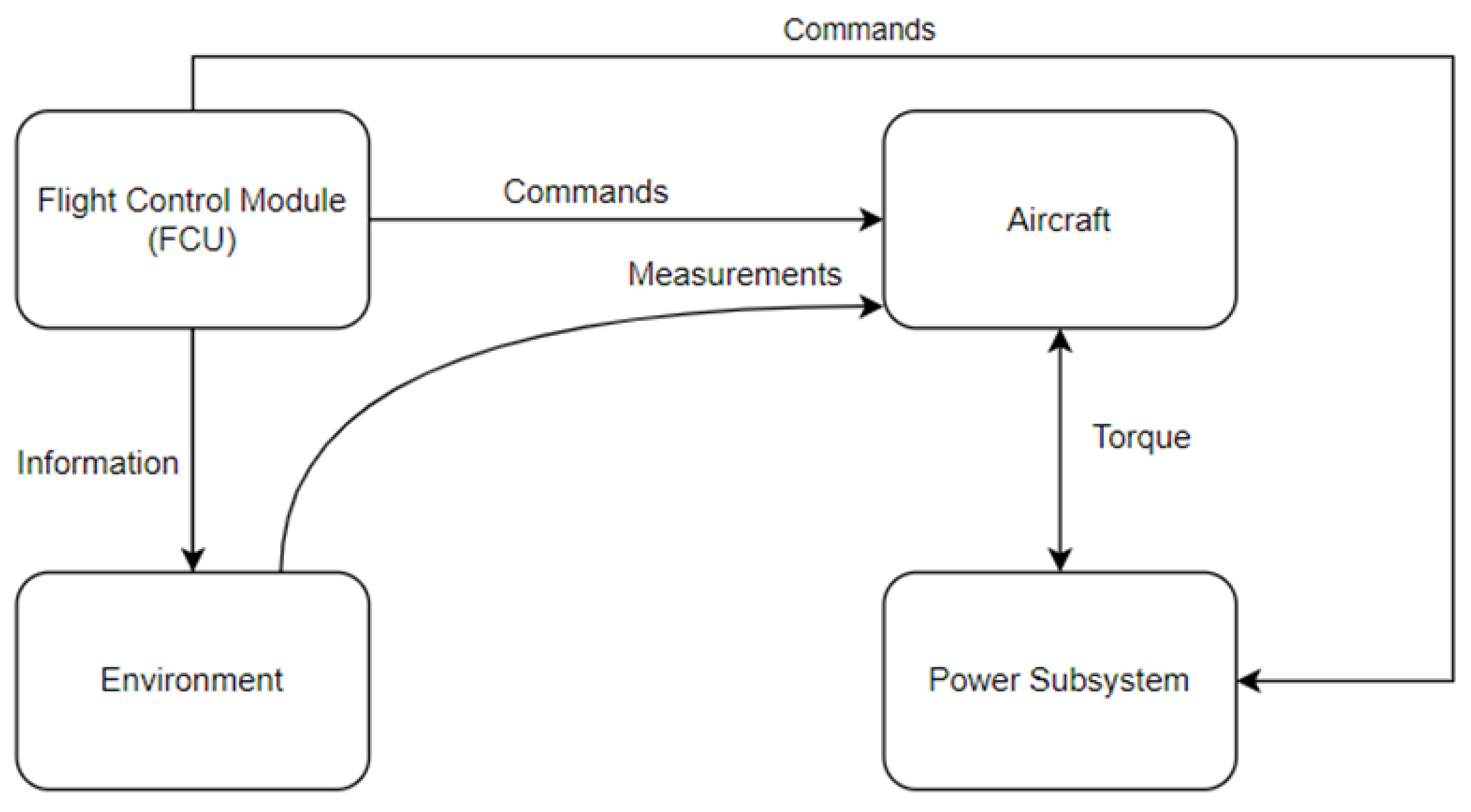
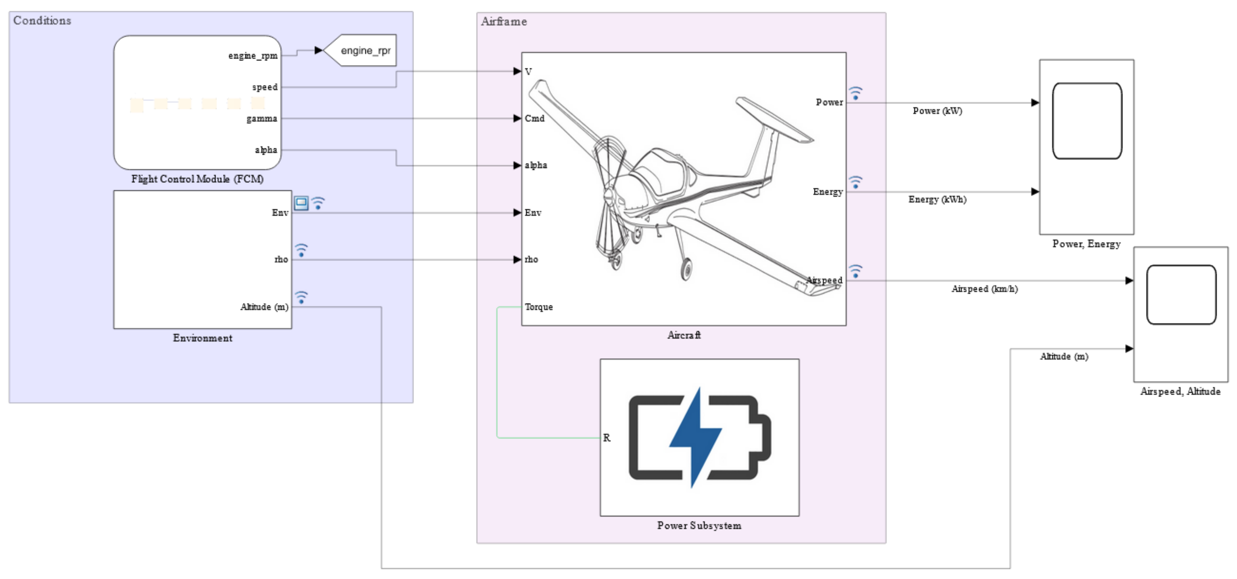
The model consists of four main subsystems (
Figure 2): Aircraft, Power Subsystem, Flight Control Module (FCU), and Environment. The Flight Control Module was developed using the Stateflow tool available in MATLAB/Simulink and it simulates a pilot controlling an aircraft. This module manages flight parameters, e.g., speeds, angle of attack, and engine rpm. Commands to change parameters are passed to the Aircraft and Power Subsystems. It also informs the Environment subsystem about the altitude change. The Environment subsystem is responsible for calculating the changes in atmospheric parameters (air density, pressure, temperature) occurring as the aircraft changes altitude. It passes this information to the Aircraft subsystem for more accurate calculations. The task of the Aircraft subsystem is to calculate, on the basis of the received parameters, the energy demand and the required torque of the aircraft to fly with the given parameters. The main elements of this subsystem are the basic formulas for the lift, thrust, and drag forces and the block that calculates the forces applied to the mass point. The basic equations used for the calculations are presented below:
where: T—thrust [N], D—drag [N], W—weight [N], γ—flight path angle [rad], q—dynamic pressure [Pa], ρ—air density [kg/m3], v—aircraft velocity [m/s], L—lift [N], S—aircraft wing area, C
L—lift coefficient, C
D—drag coefficient.
The Power Subsystem was developed with the use of Simscape, a tool for modelling physical systems, and consists of three main subsystems: Battery, including a Battery Management System (BMS), Electric Motor, and Loads. The Loads subsystem simulates the power requirements of avionics, heating (starts automatically when the aircraft exceeds a set altitude), and lighting.
The actual detailed block diagram of the simulation model of electric aircraft developed in the MATLAB-Simulink is presented in the
Appendix A (
Figure A1) in form of the pdf file and webview hyperlinked model is presented in
supplementary materials.
3.3. Model Simplifications
The following simplifications are used in the model: (1) the electric motor runs on DC, (2) the aircraft is considered as a mass point; (3) no consideration of temperature effects on battery operation; (4) the flight takes place in ideally nonwind, nonthermal conditions. In the case of the first simplification, it is related to the use of an electric motor block available in a program called Motor&Drive (System Level). The advantage of this solution is that it does not require the accurate parameterisation of the motor but only requires the definition of the torque-speed envelope. This allows identification of the required parameters of the motor performance and, on their basis, selection of the appropriate AC drive unit available on the market for the optimised simulation model. The change in the type of current is related to the fact that motors operating on alternating current are better suited for applications requiring high power and are more efficient. The most common motor used in electric vehicles and aircraft is the permanent magnet synchronous motor (PMSM). As an additional simplification, the aerodynamic coefficients of each aircraft were estimated from available data. The cruise speed has been selected with reference to ICE-powered aircraft. For electric aircraft on the market, their recommended cruise speeds are lower. On the other hand, the higher energy demand associated with manoeuvres in the air (e.g., turns) is not taken into account during flight.
As this is a preliminary study of the potential of an electric-powered aircraft, the model does not take into account the full constraints of regulations and good practices; among others, that the required diversion time for VFR flights is 30 min (cross-country) or 10 min (local) has not been taken into account.
3.4. Selection of Aircrafts
Three aircraft representing three different classes were selected for analysis: Diamond DA20 Katana, WT-9 Dynamic, and PZL-101 Gawron. The first of the mentioned has been chosen due to its popularity in Western Europe in both pilot training and recreational flying; it is also a newer construction than the Cessna 150/152. Katana was developed from motor glider Diamond HK36 Super Dimona. Compared to the WT-9, the Katana landing gear is not retractable, resulting in an increased drag coefficient. Dynamic represents a class of ultralight aircraft and can tow gliders, whereas Gawron is commonly used as an aircraft towing glider in Polish aeroclubs. PZL-101 Gawron is the oldest and the heaviest aircraft among the analysed. Its first flight took place in 1958 [
39]. The parameters of each aircraft are presented in
Table 2.
Due to the retrofitting of the analysed aircraft, only the empty weight of the aircraft has changed. This is due to the use of electric propulsion. The drag coefficient was estimated based on the aircraft configuration—vertical location of the wing, fuselage cross section, fixed or retractable landing gear. The lift coefficient was estimated using the information about airfoils used in the analysed aircraft and Equations (2) and (3). The parameters of the simulated flights were used as variables in the equations. Other parameters have been taken from Pilot’s Operating Handbooks.
A PB345V124E-L battery pack based on Li-ion cells was chosen as the power source. It is used in the Pipistrel Alpha Electro. Its basic parameters needed for the simulation are shown in
Table 3.
Each of the aircrafts analysed was equipped with two battery packs (total 20.7 kWh), which were connected in parallel to increase capacity. This is linked to the assumption that there are no changes to the aircraft geometry (retrofitting). Increasing the number of batteries results in a significant increase in the weight of the aircraft and a reduction in the payload that can be carried. In addition, it would increase the difficulty of quickly replacing a flat battery with a new one and significantly increase the cost of the aircraft. To secure enough battery power to avoid damage and allow safe landing at or off airports depending on the aircraft position, the lowest possible battery discharge level was assumed to be 20% (which means that the remaining level of energy capacity is equal to 12 Ah and the remaining energy rating is 4.14 kWh).
3.5. Analysed Missions
The following tasks were selected for analysis: cross-country flight, performing the touch-and-go procedure—which is the basic training for pilots or student pilots—and towing gliders. Based on the data collected from the pilots and using the flight records, parameters were developed that are satisfactory and allow the achievement of goals for each of the tasks. For flights, according to the collected data, the minimum range should be 300 km and a speed range between 90 and 110 kts (167–205 km/h). For the touch-and-go procedure, the aircraft should be able to perform between 8 and 10 touch-and-go procedures (from a practical point of view, this means performing between 9 and 11 landings). The towing aircraft should be able to perform at least 10 tows, which are usually performed at a speed of about 120 km/h and a climb rate of 1.5 m/s. In case of towing, there are training tows at about 300 m above the ground level and thermal tows at least 600 m above the ground level.
3.5.1. Case 1: Cross-Country Flight
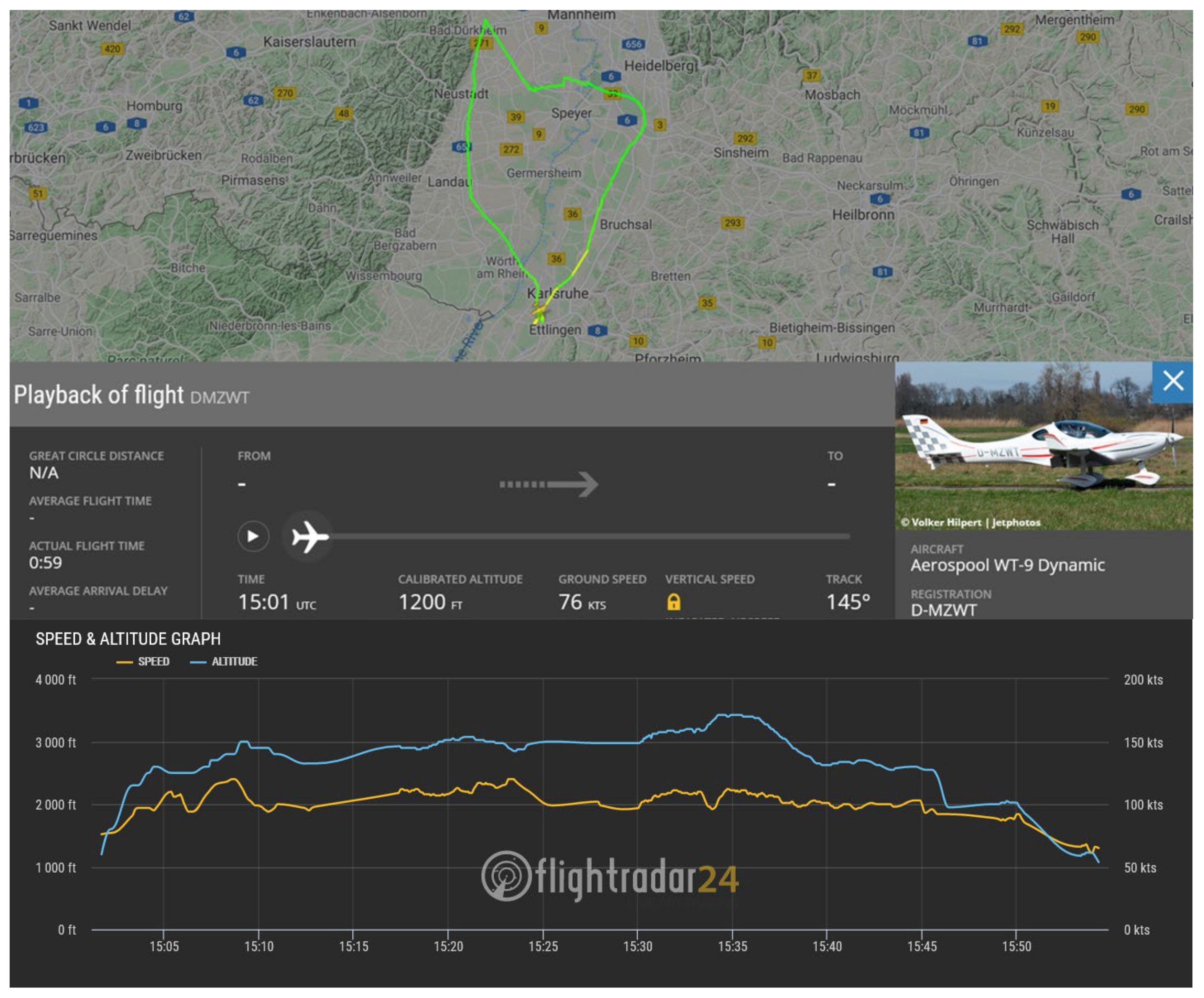
Diamond DA20 Katana and WT-9 Dynamic were selected for the first task, where they were to perform the longest flight possible. Cruise speed and altitude were selected based on a sample flight of the Dynamic aircraft recorded on Flightradar24 (
Figure 3). Other speeds and the rate of climb (ROC) were taken from
Table 3. The rate of descent (ROD) is the same for each aircraft. The flights are carried out with a crew of two.
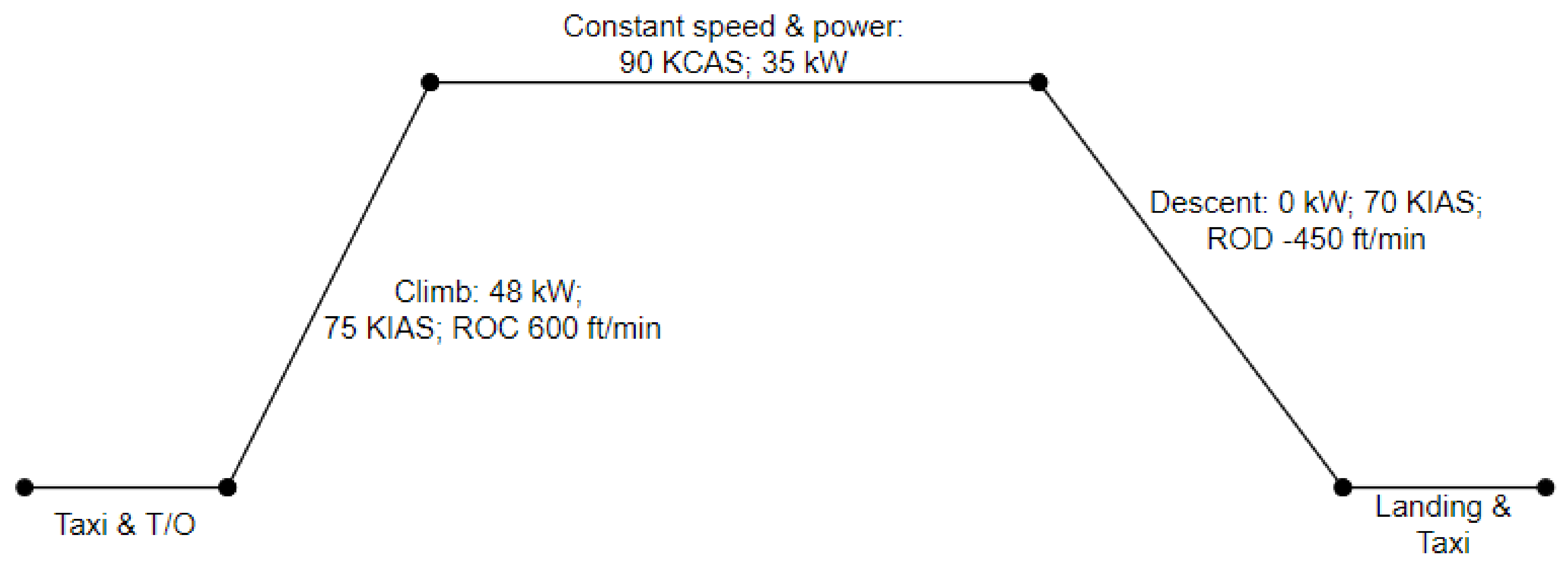
Table 4 shows the flight parameters for both aircraft.
3.5.2. Case 2: Touch-and-Go Procedure
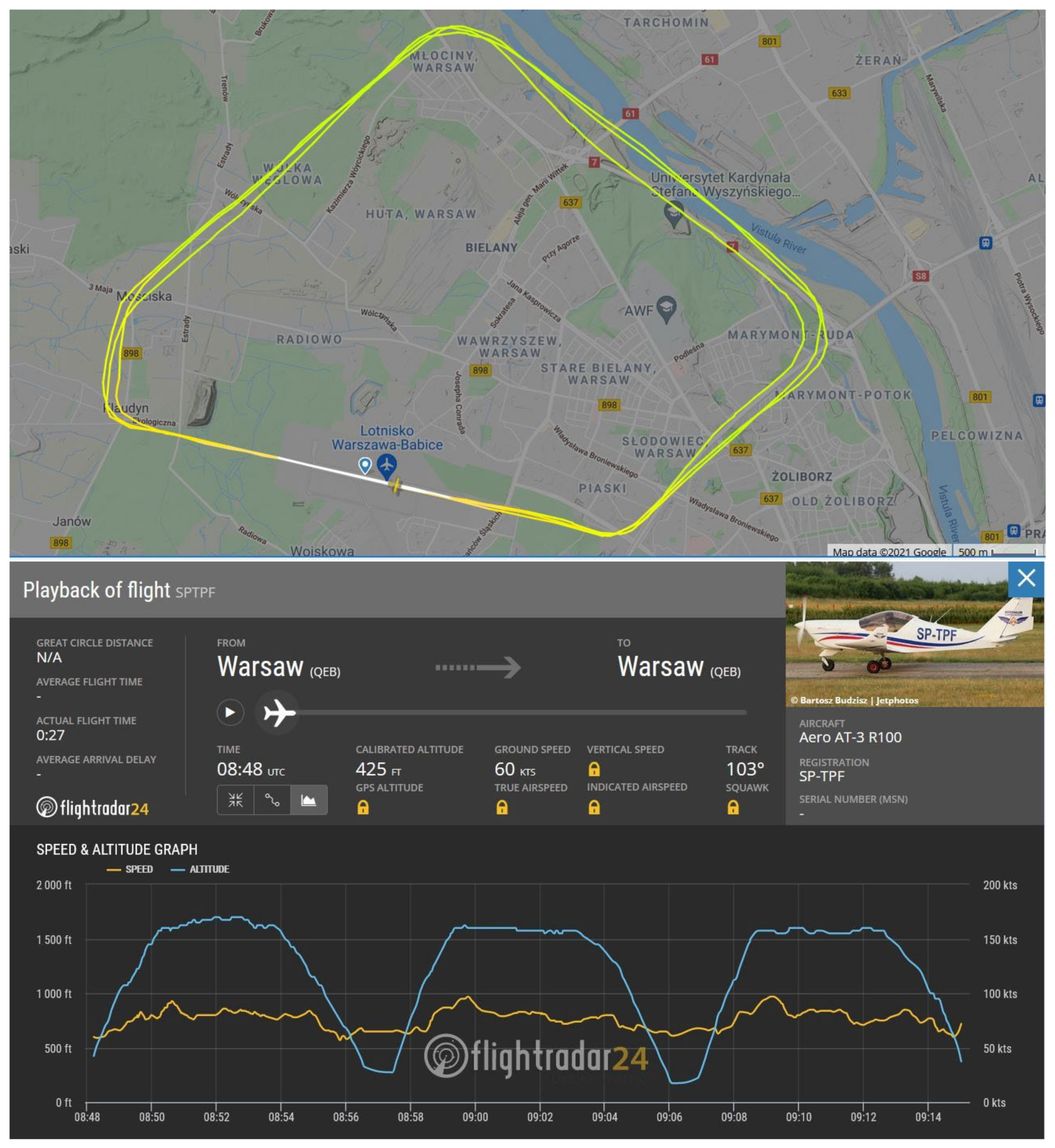
The parameters for simulating the performance of a touch-and-go procedure were modelled on data obtained from Flightradar24 (
Figure 4). For this recorded flight, the aircraft performed the touch-and-go procedure twice (three landings) at Warszawa-Babice Airport (EPBC). This airport is known for a very strict noise standard due to the proximity of residential buildings. In view of this, the use of electric aircraft would be advisable at this airport. The simulated traffic pattern was also based on the mandatory traffic pattern at this airport, which is approximately 20.250 km long. The elevation of the airport is 130 m above sea level, and the height at which the traffic pattern was carried out was 350 m above ground level. Two aircrafts, with two people onboard, were compared in the simulation: the Diamond DA20 Katana and the WT-9 Dynamic. The average flight speed in the traffic pattern was 160 km/h. The other flight parameters are as recommended by the manufacturers. The data for this simulated task are presented in
Table 5.
3.5.3. Case 3: Glider Towing
For this task, two very different structures were chosen for comparison—the PZL-101 Gawron, which was designed in the 1950s, and the WT-9 Dynamic representing the Ultralight (UL) aircraft class. In the simulation, the glider parameters being towed are similar to the SZD-9 Bocian. The flight parameters of the towing aircraft were developed based on the data obtained from the pilots and are given in
Table 6. Each aircraft made two tows—one training at 300 m AGL and the other at 600 m AGL.
4. Results
The simulations were performed using the MATLAB/Simulink software. The analysed missions included the following flight stages: runway run-up, climb, cruise, descent, runway deceleration, and runway exit or glider approach in the case of towing aircraft. The last stage is related to the safety of other pilots because if the aircraft cannot leave the runway, it results in closure. Each case was analysed that way.
4.1. Model Verification
The developed simulation model was verified using data from a real electric aircraft, Pipistrel Velis Electro. The aircraft and flight parameters were implemented into the model, and then the obtained power demand results were compared with the manufacturer’s data (
Figure 5).
Table 7 shows the results and the differences between them.
The results obtained from the simulation indicate a lower power consumption of the aircraft than is realistic. Nevertheless, the obtained simulation results should be considered as very correct and validates the usefulness of this model at this stage of the analysis; the lower than realistic level of power demand is justified by simplifications in the models and not taking into account the difficulty of estimating the impact of additional factors that usually increase energy consumption, such as additional maneuvers and flight corrections, wind, temperature, and underestimation of lift and drag coefficients.
The above model can be used to evaluate electric aircraft during the initial stages of concept definition, and also after successive improvement during the development of the individual project as well as throughout the design and analysis process.
4.2. Case 1: Cross-Country Flight
According to the minimum requirements for a cross-country flight, the minimum range should be 300 km and the speed should be in the range of 167–205 km/h. Flight parameters are shown in
Table 2. During the simulation of this task, the maximum range with a safe reserve of 20% battery charge of the analysed aircraft is tested (battery depth of discharge is 80%).
In the case of the Diamond DA20 Katana aircraft, the maximum flight distance was 64.75 km and during taxiing it covered an additional 2.42 km (67.17 km in total). The entire operation was completed in approximately 28 min. The battery was discharged to 20.05% and during descent, energy recovery allowed the battery to recharge by approximately 3.39%, reducing energy consumption by 0.45 to 11.1 kWh (
Figure 6).
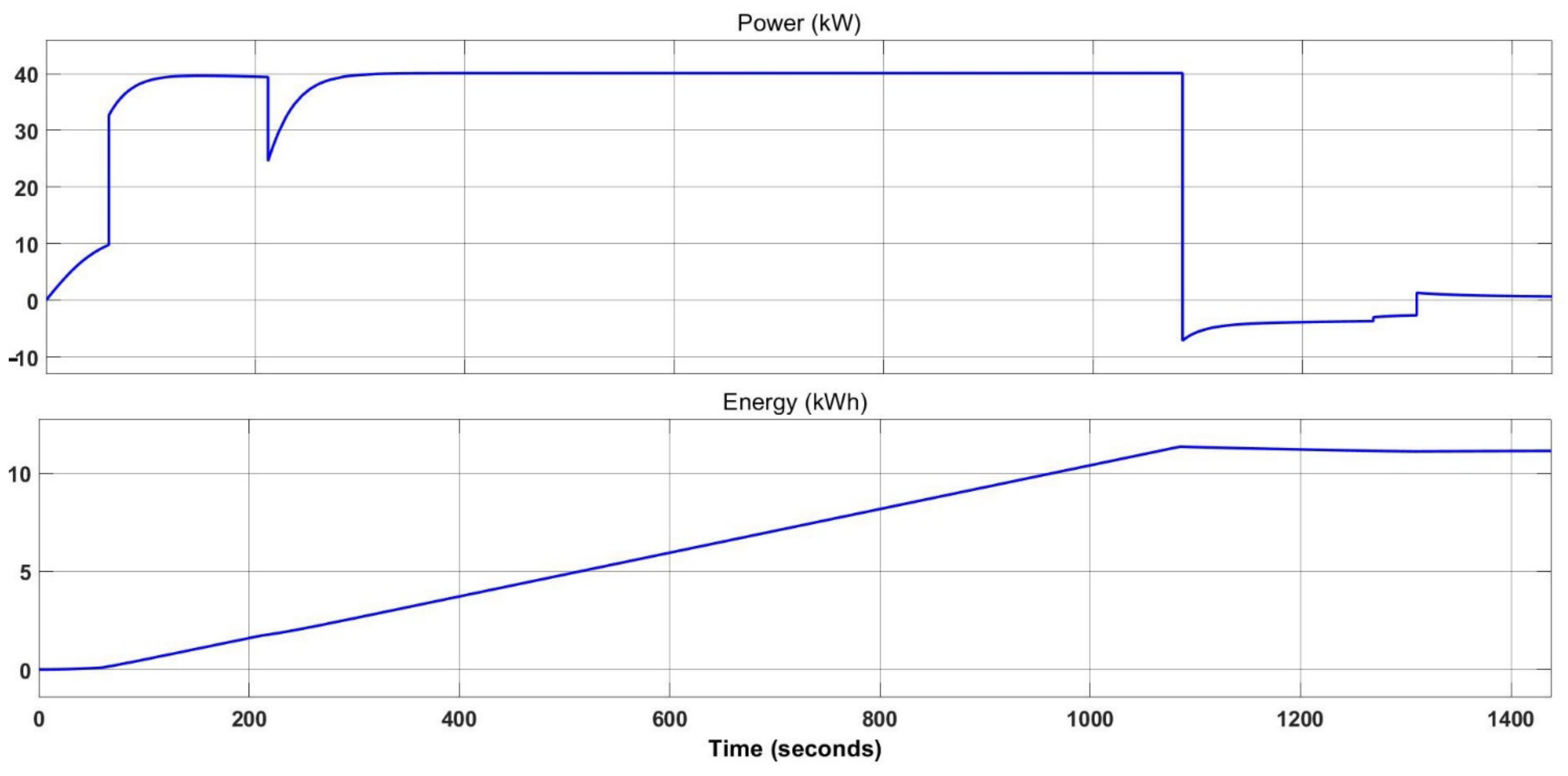
The WT-9 Dynamic had a planned route of 114 km, during which, including the necessary taxiing on the ground, the aircraft covered a total distance of 115.8925 km in nearly 44 min. At the transition from cruise to descent, the battery charge was 20.93%, the descent phase recharged it to 22.88%, and the additional taxiing brought the battery charge down to 22.20%. The maximum energy consumption was reached at the end of the cruise phase and amounted to 11.434 kWh, while due to recuperation during descent, the total energy consumption dropped to 11.154 kWh. Taxiing, after landing, raised energy consumption to 11.17 kWh (
Figure 7).
Table 8 summarises the simulation results obtained for Diamond DA20 Katana and WT-9 Dynamic.
4.3. Case 2: Touch-and-Go Procedure
Table 5 shows the mission parameters with two touch-and-go procedures at Babice Airport (EPBC). The aircraft should be able to repeat this between 8 and 10 times. Simulations were carried out until the battery charge reached 20% or until the target number of touch-and-go was reached.
The simulation performed for the Diamond DA20 Katana showed that the aircraft successfully completed the planned mission. The total energy consumption was 8.6 kWh (
Figure 8). The battery was discharged to the level of 45%. The aircraft completed its mission in about 32 min, covering 64.7 km in that time. During descent and landing, the battery increased its charge level by 0.08%. The Diamond DA20 Katana can perform a maximum of three touch-and-go procedures, consuming 11.3 kWh. It covers a total of 85.42 km in 41 min. The battery charge level at the end of the mission was 22.82%.
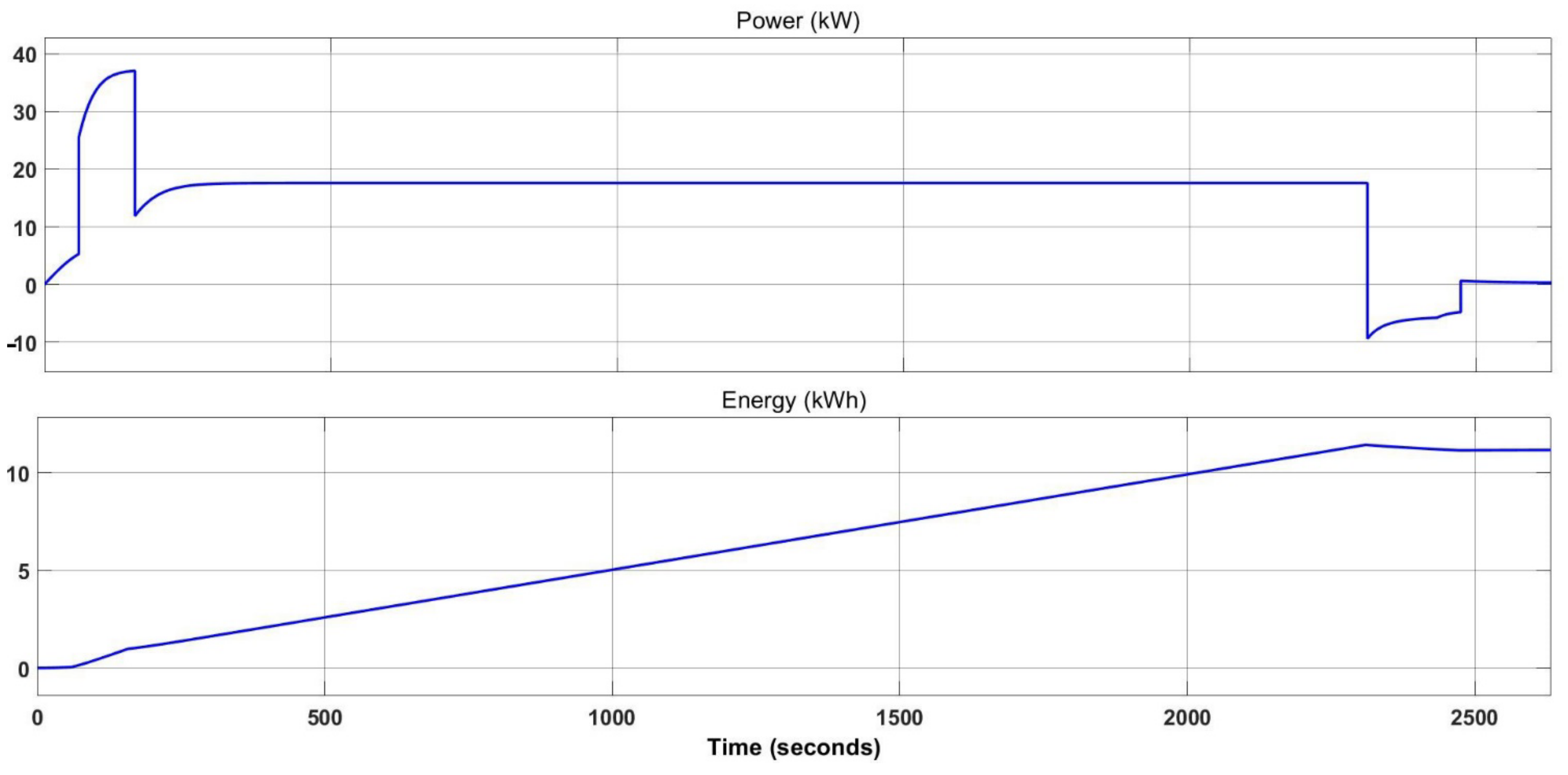
The WT-9 Dynamic aircraft also successfully completed the planned mission. The two touch-and-go procedures took 30 min to complete and the distance covered, including the necessary taxiing, was 65 km. As with the Diamond DA20 Katana, Dynamic charged the batteries by 0.52% during descent and landing on the runway. During the mission, the aircraft’s power consumption was 6 kWh (
Figure 9) and the batteries were discharged to the level of 61%. WT-9 Dynamic can perform a maximum of four touch-and-go procedures, consuming 10 kWh. It covers a total of 106.6 km in 49 min. The battery charge level at the end of the mission was 30.92%.
Table 9 compares the flight parameters obtained during the simulation of performing two touch-and-go procedures at Babice Airport (EPBC) for Diamond DA20 Katana and WT-9 Dynamic with electric motors.
4.4. Case 3: Glider Towing
The towing aircraft should be able to perform at least 10 tows without refueling. PZL-101 Gawron can perform an average of 15 tows on a single tank. For each aircraft, two simulations were performed, tow on 300 m and tow on 600 m.
Table 6 presents the flight parameters.
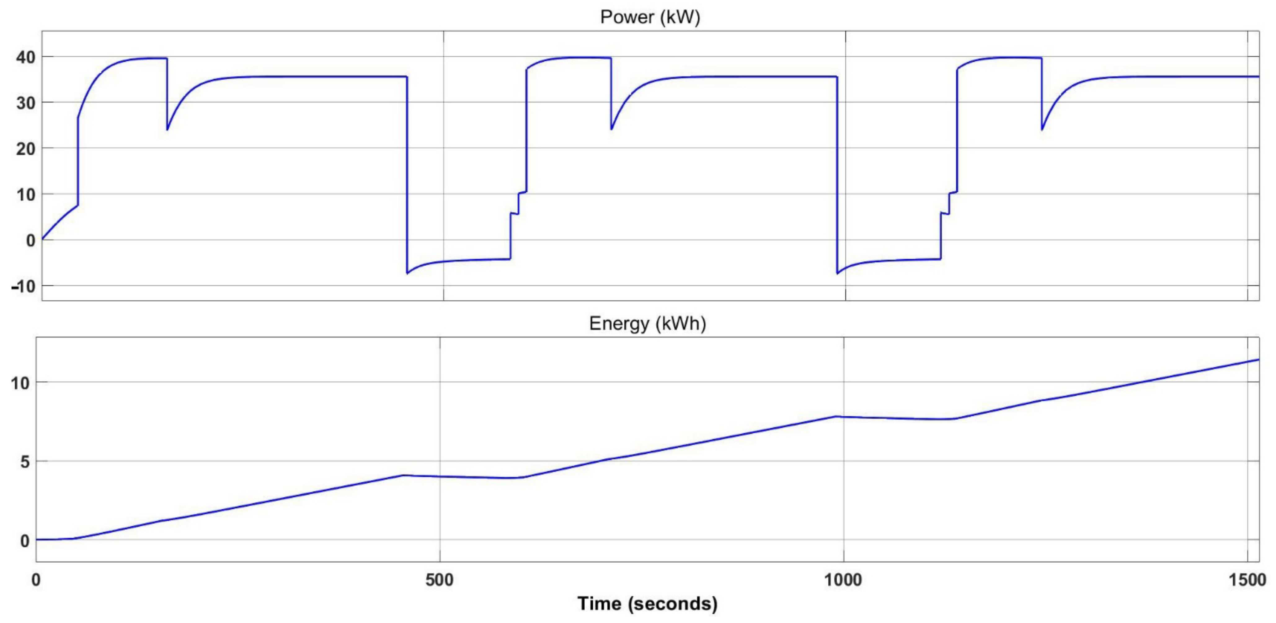
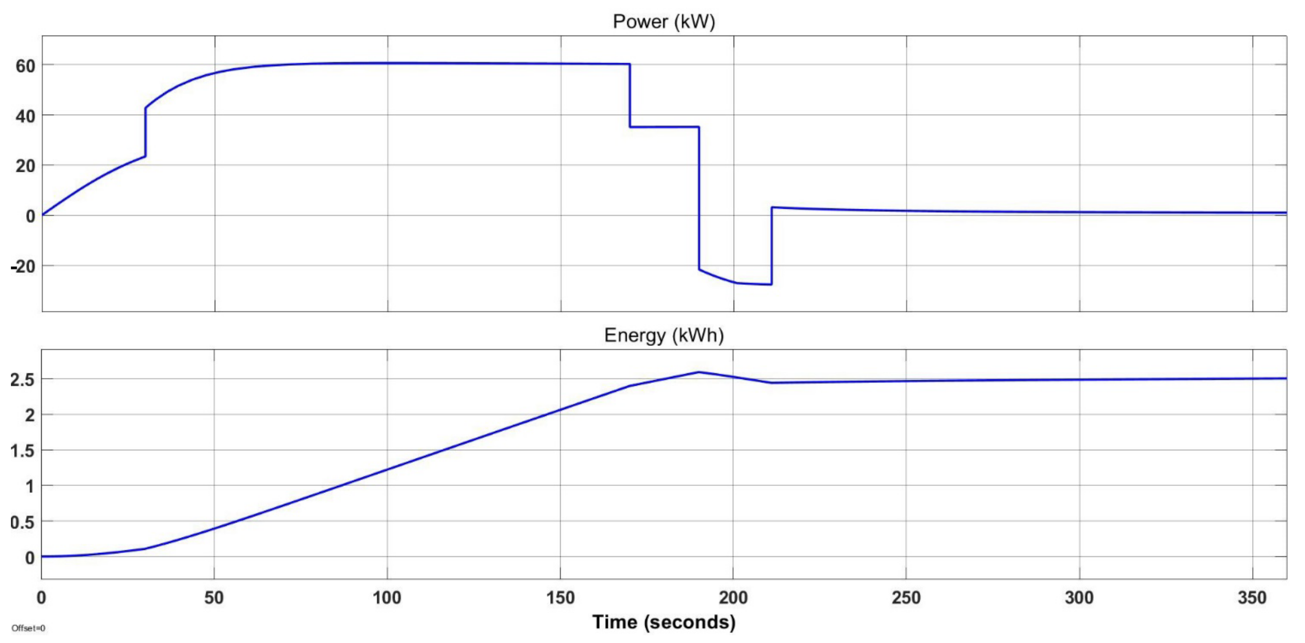
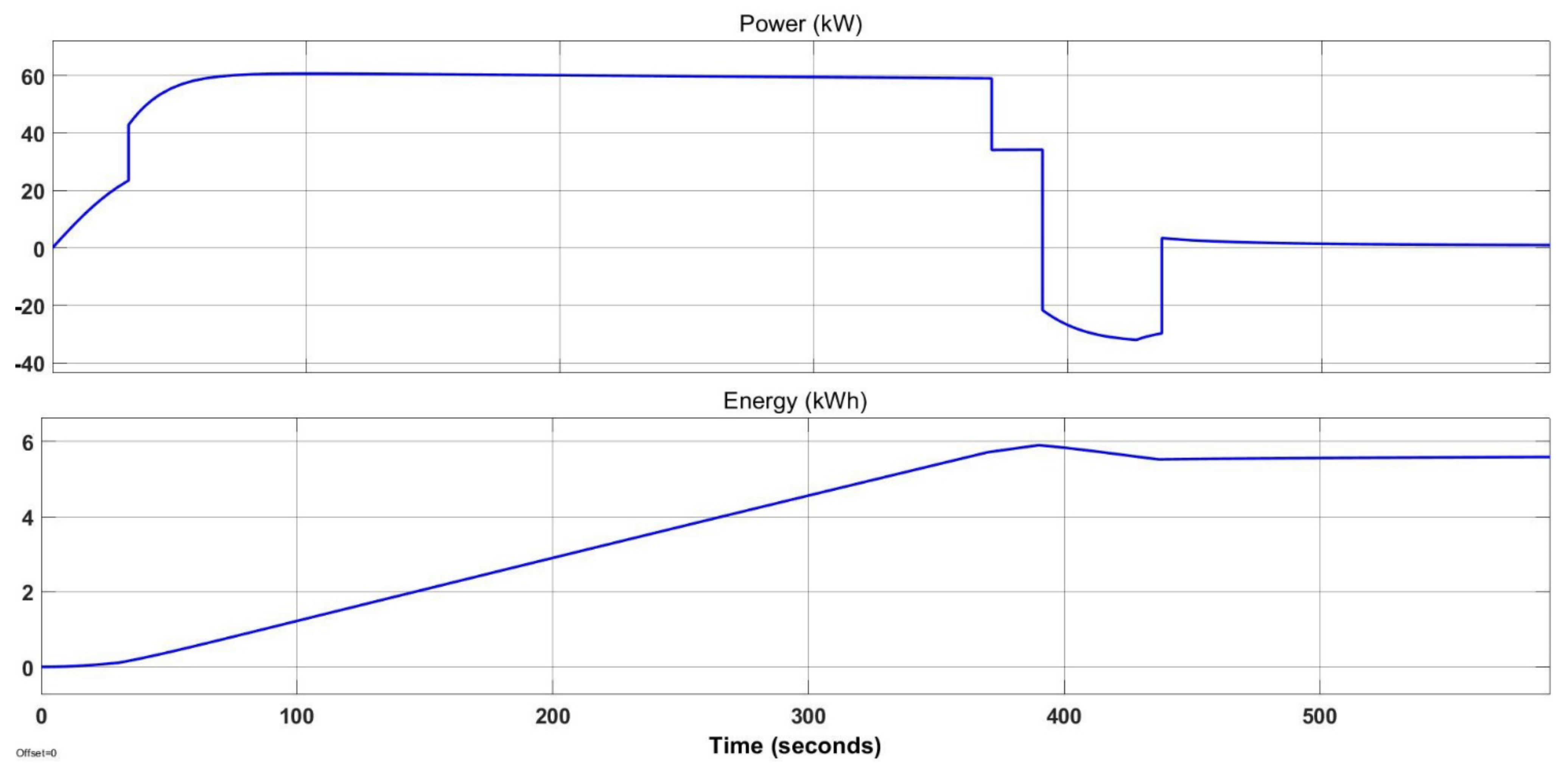
The PZL-101 Gawron aircraft during towing to a height of 300 m above ground level (AGL) and, after landing, taxiing to another glider discharges the battery by about 20%, while in case of towing to the height of 600 m AGL the demand for battery energy is twice as high. This gives the possibility to perform towing 4 and 2 times, respectively, without the need to recharge or change the battery. During such a tow, the highest total energy consumption is 2.6 and 5.9 kWh respectively, while descending reduces this to 2.50 and 5.6 kWh, correspondingly (
Figure 10 and
Figure 11).
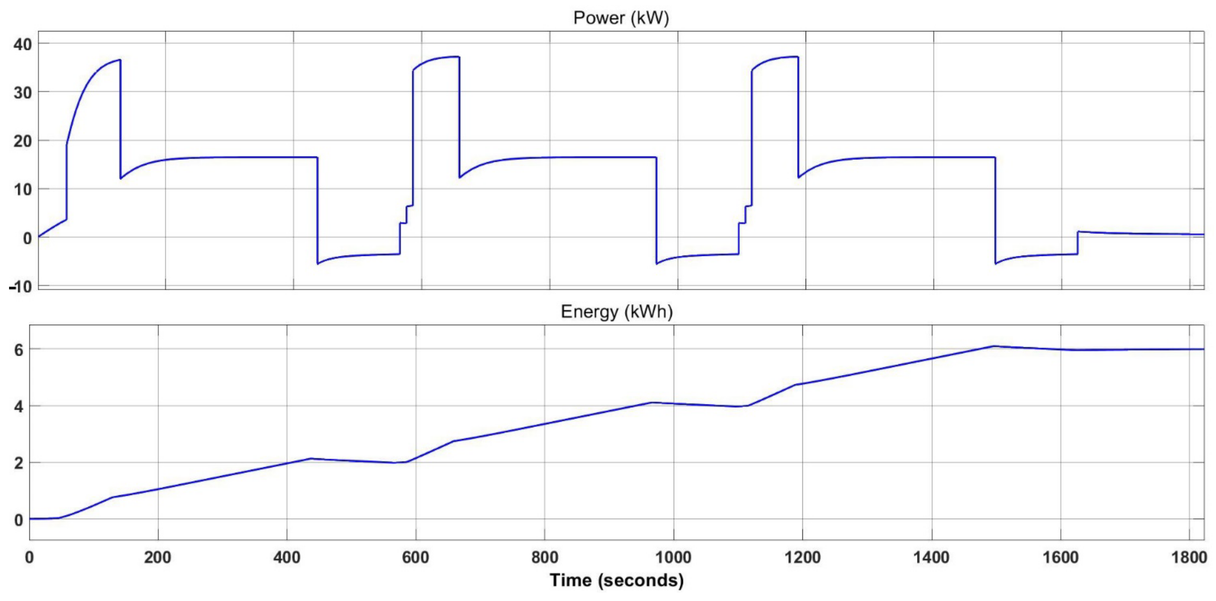
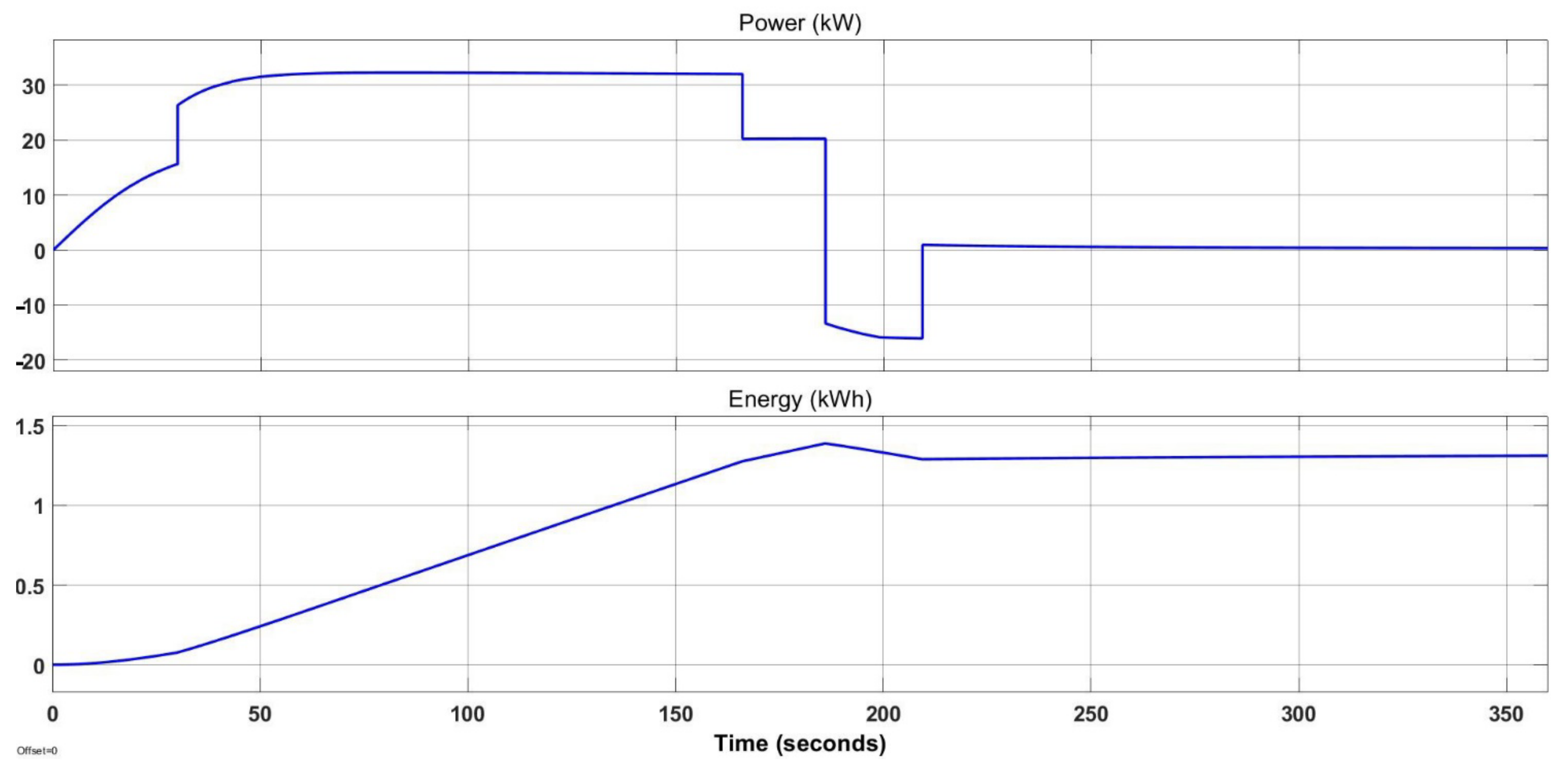
In case of the WT-9 Dynamic version adapted to towing gliders, it is possible to perform towing 8 times to a height of 300 m AGL or 4 to a height of 600 m AGL. In the first case, the maximum energy consumption was 1.4 kWh, while energy recovery during the descent reduced it to 1.31 kWh (
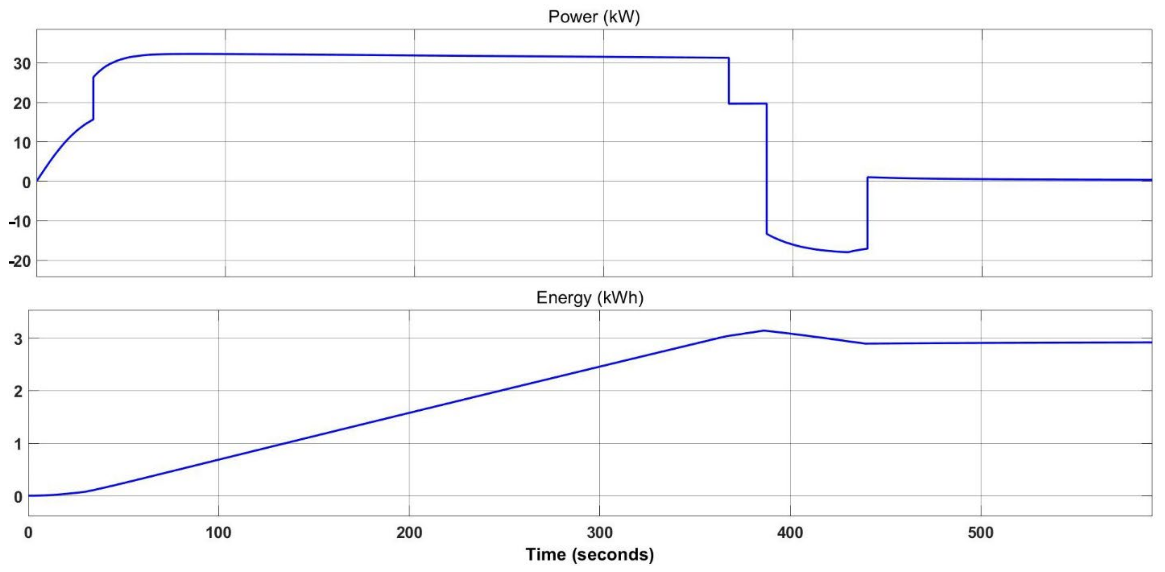
Figure 12). Each tow consumes about 10% of the battery energy. The battery increases its charge level by 0.6% during this stage of the flight. Simulation of the tow to a higher altitude showed that the final energy consumption was 2.92 kWh, which is 0.23 kWh lower than the maximum (
Figure 13). Such a tow reduces the battery charge by about 20%. Descending the aircraft allows the battery to recharge by 1.2%.
Table 10 compares the flight parameters of the Gawron and Dynamic aircraft when towing a glider.
4.5. Predictions
According to data from 2009–2019, the energy density of Li-ion batteries improved by about 10% each year [
46]. Taking this trend as a constant, simple analyses have been performed to estimate the year in which the electric aircraft will reach the assumed minimum requirements.
The minimum requirements are as follows:
The range of flight 300 km;
Performing 8 touch-and-go procedures;
Perform 10 tows at height 300 and 600 m.
Table 11 shows the approximate dates on which the aircraft representing each class with the electrical propulsion system would reach the minimum requirements set by the users. It should be taken into account that these are only projections based on the trend of increasing battery energy density observed between 2009 and 2019.
Due to the fact that better results were obtained from the simulation model than in reality, it is more likely that the analysed aircraft will reach the minimum requirements 1 or 2 years later than predicted in
Table 11. In the next steps, the predictive models will be refined so that it is possible to apply more sophisticated criteria and apply to the issues of energy consumption optimisation as well as flight route planning and flight strategy in accordance with the methodology already used by the authors [
47].
5. Conclusions
The paper presents an analysis of potential small General Aviation aircraft with electric propulsion. For this purpose, three existing designs with combustion engines, representing different classes of aircraft, were selected. The main objective of the simulations was to assess the feasibility of using electric aircraft equipped with currently available batteries in the context of performing various tasks (cross-country flight, touch-and-go procedure, glider towing). Finally, additional simulations were carried out to determine approximate dates for electric aircraft to reach minimum requirements, based on the observed trend of increasing the battery energy density.
For the simulation, the parameters of existing conventionally powered aircrafts were used, which were “virtually” retrofitted with electric propulsion. The selection of individual models was carried out on the basis of the collected information on their universality and usability. In case of an aircraft designed from scratch as electric, one can expect to obtain better performance than in the analysed cases. It is especially visible in the case of the older construction of the PZL-101 Gawron aircraft.
Based on the simulations carried out, it can be seen that the greatest potential for use at this point (2021) in battery development is with an electric ultralight class aircraft. Simulations have shown that the mass of an electric aircraft has the greatest impact on its performance. Currently, such an aircraft would be best suited for flights close to airports, performing touch-and-go procedures or towing gliders to lower altitudes requiring a large change in operating power during operation. For the latter task, it is expected to reach minimum requirements as early as 2022. Simulation of the first task indicates that it is already reasonable to consider starting basic pilot training (touch-and-go procedures) with the use of an electric ultralight aircraft. This would also reduce the cost per flight hour.
The use of methods of Model Based System Engineering allows assessment of the purposefulness of ongoing design work on new types of electrically powered aircraft. Using this methodology, it is possible to verify the potential use of a given aircraft in the implementation of a selected task and estimate the parameters of the engine and batteries. It also allows for determination of the most appropriate cruising speed for new electric aeroplanes. The method can also be successfully used to optimise the parameters of newly designed aeroplanes and their propulsion systems, allowing the improvement of their final functional characteristics. In this context, it can be successfully stated that the time perspective specified in the forecast should be shortened. The analysis did not take into account possible—but difficult to predict—revolutionary changes in battery technology. Due to the significant involvement of the scientific potential in these works, it can be considered that, thanks to such discoveries, progress may be faster than assumed.
Further research will be conducted towards the use of MBSE methods in the analysis of low emission propulsion systems for aviation. This is related to facilitating the management of the entire life cycle of the designed systems, which allows the delivery of a better product along with a reduction in costs. Work is currently underway to include additional energy sources in the simulation model, such as fuel cells and photovoltaic cells, and is focused on optimisation of energy consumption and aircraft design. The methodology itself will be developed by the authors in application to other cases, i.e., High-Altitude Long-Endurance Unmanned Aerial Vehicles and autonomous vehicles.
Author Contributions
Conceptualisation, M.P. and W.S.; methodology, M.P., W.S.; software, M.P.; validation, M.P., W.S.; formal analysis, M.P. W.S.; investigation, M.P.; resources, M.P., W.S.; data curation, M.P.; writing—original draft preparation, M.P.; writing—review and editing, M.P., W.S.; visualisation, M.P.; supervision, W.S.; project administration, M.P., W.S.; funding acquisition, M.P., W.S. All authors have read and agreed to the published version of the manuscript.
Funding
This research was partially founded from EEA and Norway Grants 2014–2021 and was partially carried out in the framework of the project No. NOR/POLNOR/LEPolUAV/0066/2019 Long-endurance UAV for collecting air quality data with high spatial and temporal resolutions”. This work has been also supported by Silesian University of Technology (grant no. 10/060/BKM21/2011). The APC was funded by Silesian University of Technology.
Data Availability Statement
The data presented in this study are available in the article and supplementary material.
Conflicts of Interest
The authors declare no conflict of interest.
Appendix A. The Simulation Model of Electric Aircraft Developed in the MATLAB-Simulink Environment
Figure A1.
The simulation model of electric aircraft developed in the MATLAB-Simulink environment.
Figure A1.
The simulation model of electric aircraft developed in the MATLAB-Simulink environment.
References
- BP. Statistical Review of World Energy. Available online: https://www.bp.com/en/global/corporate/energy-economics/statistical-review-of-world-energy/oil.html (accessed on 29 November 2021).
- ICAO. 2019 Environmental Report. Available online: https://www.icao.int/environmental-protection/Pages/envrep2019.aspx (accessed on 29 November 2021).
- EESI. The Growth in Greenhouse Gas Emissions from Commercial Aviation. October 2019 (revised September 2021). Available online: https://www.eesi.org/files/FactSheet_Climate_Impacts_Aviation_1019.pdf (accessed on 29 November 2021).
- European Commission. Flightpath 2050. Available online: https://op.europa.eu/en/publication-detail/-/publication/296a9bd7-fef9-4ae8-82c4-a21ff48be673 (accessed on 29 November 2021).
- European Commission. The European Green Deal. Available online: https://eur-lex.europa.eu/legal-content/EN/TXT/?uri=CELEX%3A52019DC0640 (accessed on 29 November 2021).
- Cameretti, M.C.; Del Pizzo, A.; Di Noia, L.P.; Ferrara, M.; Pascarella, C. Modeling and Investigation of a Turboprop Hybrid Electric Propulsion System. Aerospace 2018, 5, 123. [Google Scholar] [CrossRef] [Green Version]
- Stan, C. Alternative Propulsion for Automobiles; Springer International Publishing: Cham, Switzerland, 2017. [Google Scholar]
- National Academies of Science, Engineering and Medicine. Electric Propulsion. In Commercial Aircraft Propulsion and Energy Systems Research: Reducing Global Carbon Emissions; The National Academies Press: Washington, DC, USA, 2016; Chapter 4. [Google Scholar]
- IATA. Sustainable Aviation Fuels. Available online: https://www.iata.org/contentassets/d13875e9ed784f75bac90f000760e998/saf-and-sustainability.pdf (accessed on 29 November 2021).
- Xie, Y.; Savvaris, A.; Tsourdos, A.; Laycock, J.; Farmer, A. Modelling and Control of a Hybrid Electric Propulsion System for Unmanned Aerial Vehicles. In Proceedings of the 2018 IEEE Aerospace Conference, Big Sky, MT, USA, 3–10 March 2018. [Google Scholar]
- Ribold, C.E.D.; Gualdoni, F.; Trainelli, L. Preliminary weight sizing of light pure-electric and hybrid-electric aircraft. Transp. Res. Procedia 2018, 29, 376–389. [Google Scholar] [CrossRef]
- Vepa, R. Electric Aircraft Dynamics: A Systems Engineering Approach; CRC Press: Boca Raton, FL, USA, 2020. [Google Scholar]
- Sadraey, M.H. Aircraft Design: A Systems Engineering Approach; Wiley: Chichester, UK, 2012. [Google Scholar]
- Faraz, A.; Ambikapathy, A.; Thangavel, S.; Logavani, K.; Prasad, G.A. Battery Electric Vehicles (BEVs). In Electric Vehicles, Green Energy and Technology; Springer: Singapore, 2021. [Google Scholar]
- Think:Act. Aircraft Electrical Propulsion—The Next Chapter of Aviation? Roland Berger Ltd.: London, UK, 2017. [Google Scholar]
- Yokota, K.; Fujimoto, H.; Hori, Y. Descent Angle Control by Regenerative Air Brake Using Observer-based Thrust Control for Electric Aircraft. In Proceedings of the AIAA Propulsion and Energy 2020 Forum, Virtual Event, 24–28 August 2020. [Google Scholar]
- Kim, H.D.; Perry, A.T.; Ansell, P.J. A Review of Distributed Electric Propulsion Concepts for Air Vehicle Technology. In Proceedings of the 2018 AIAA/IEEE Electric Aircraft Technologies Symposium, Cincinnati, OH, USA, 9–11 July 2018. [Google Scholar]
- Reimers, J.O. Introduction of Electric Aviation in Norway. Feasibility Study by Green Future AS. Available online: https://avinor.no/contentassets/c29b7a7ec1164e5d8f7500f8fef810cc/introduction-of-electric-aircraft-in-norway.pdf (accessed on 30 November 2021).
- European Aviation Safety Agency. Type Certificate Data Sheet for Type Virus SW 121 (EASA.A.573); European Aviation Safety Agency: Cologne, Germany, 2020. [Google Scholar]
- Hospodka, J.; Bínová, H.; Pleninger, S. Assessment of All-Electric General Aviation Aircraft. Energies 2020, 13, 6206. [Google Scholar] [CrossRef]
- IEA. European Electricity Supply in 2020, IEA, Paris. Available online: https://www.iea.org/data-and-statistics/charts/european-electricity-supply-in-2020 (accessed on 1 December 2021).
- Trainelli, L.; Salucci, F.; Riboldi, C.E.D.; Rolando, A.; Bigoni, F. Optimal Sizing and Operation of Airport Infrastructures in Support of Electric-Powered Aviation. Aerospace 2021, 8, 40. [Google Scholar] [CrossRef]
- Folkson, R. Alternative Fuels and Advanced Vehicle Technologies for Improved Environmental Performance. Towards Zero Carbon Transportation; Woodhead Publishing: London, UK, 2014. [Google Scholar]
- Nitta, N.; Wu, F.; Lee, T.J.; Yushin, G. Li-ion battery materials: Present and future. Materials Today 2015, 18, 5. [Google Scholar] [CrossRef]
- Bruce, P.G.; Hardwick, L.J.; Abraham, K.M. Lithium-air and lithium-sulfur batteries. Mater. Res. Soc. 2011, 36, 506–512. [Google Scholar] [CrossRef]
- Niestrój, R.; Rogala, T.; Skarka, W. An Energy Consumption Model for Designing an AGV Energy Storage System with a PEMFC Stack. Energies 2020, 13, 3435. [Google Scholar] [CrossRef]
- Casals, L.C.; García, B.A.; Canal, C. Second life batteries lifespan: Rest of useful life and environmental analysis. J. Environ. Manag. 2019, 232, 354–363. [Google Scholar] [CrossRef] [PubMed]
- Aerospace Technology. Extra 330LE Electric Aircraft. Available online: https://www.aerospace-technology.com/projects/extra-330le-electric-aircraft/ (accessed on 2 December 2021).
- Aerospace Technology. E-Fan Electric Aircraft. Available online: https://www.aerospace-technology.com/projects/e-fan-electric-aircraft/ (accessed on 2 December 2021).
- Pipistrel. Alpha Electro (Prototype Name Was WATTsUP), the New 2-Seat Electric Trainer: The Greenest Way of Learning to Fly! Available online: https://www.pipistrel.ad/training/alpha-electro (accessed on 2 December 2021).
- Pipistrel. Information about Pipistrel Alpha Electro. Available online: https://www.pipistrel-usa.com/alpha-electro/ (accessed on 2 December 2021).
- Pope, S. Pipstrel Alpha Electro Coming to U.S. Flight Training Market Next Year? Flying 27 July 2018. Available online: https://www.flyingmag.com/pipstrel-alpha-electro-coming-to-us-flight-training-market-next-year/ (accessed on 4 December 2021).
- Hanley, S. Rolls-Royce Sets Electric Airplane Speed Record. Available online: https://cleantechnica.com/2021/11/26/rolls-royce-sets-electric-airplane-speed-record/ (accessed on 29 November 2021).
- Lipscombe-Southwell, A. Rolls-Royce Claims Its All-Electric Plane is the Fastest ever Made. Available online: https://www.sciencefocus.com/news/rolls-royce-claims-its-all-electric-plane-is-the-fastest-ever-made/ (accessed on 29 November 2021).
- Beery, P.; Paulo, E. Application of Model-Based Systems Engineering Concepts to Support Mission Engineering. Systems 2019, 7, 44. [Google Scholar] [CrossRef] [Green Version]
- Mateja, K.; Skarka, W. Towards energetic autonomy of UAV. Transdisciplinary engineering for complex socio-technical systems—real-life applications. In Proceedings of the 27th ISTE International Conference on Transdisciplinary Engineering, 1–10 July 2020; Pokojski, J., Gil, M., Newnes, L., Stjepandić, J., Wognum, N., Eds.; IOS Press: Amsterdam, The Netherlands, 2020; pp. 423–432. Available online: http://ebooks.iospress.nl/volumearticle/55605 (accessed on 3 December 2021).
- MathWorks. Electrical Component Analysis for Hybrid and Electric Aircraft. Available online: https://www.mathworks.com/help/aeroblks/Electrical-Component-Analysis-Hybrid-and-Electric-Aircraft.html (accessed on 20 March 2021).
- Horrein, L.; Bouscayrol, A.; Delarue, P.; Verhille, J.N.; Mayet, C. Forward and Backward simulations of a power propulsion system. IFAC Proc. Vol. 2012, 45, 441–446. [Google Scholar] [CrossRef] [Green Version]
- PZL-101A Gawron Airplane Flight Manual. Available online: https://nakolannik.pl/pzl-101a-gawron-instrukcja-uzytkowania-w-locie/ (accessed on 7 October 2021).
- Diamond Aircraft. DA20-C1 Airplane Flight Manual; Diamond Aircraft Industries Inc.: London, ON, Canada, 2012. [Google Scholar]
- Producer Website. Available online: https://lsa.aerospool.sk/ (accessed on 29 October 2021).
- Pipistrel. Available online: https://www.pipistrel-aircraft.com/aircraft/electric-flight/batteries-systems-and-bms/ (accessed on 30 September 2021).
- Flight History for Aircraft—D-MZWT. Flightradar24. Available online: https://www.flightradar24.com/data/aircraft/d-mzwt (accessed on 29 October 2021).
- Flight History for Aircraft—SP-TPF. Flightradar24. Available online: https://www.flightradar24.com/data/aircraft/sp-tpf (accessed on 29 October 2021).
- Pipistrel. Pilot’s Operating Handbook; VELIS Electro Non Type Certified. Document No.: POX-X128-00-40-001; Pipistrel: Aj-dovščina, Slovenia, 2021. [Google Scholar]
- Löbberding, H.; Wessel, S.; Offermanns, C.; Kehrer, M.; Rother, J.; Heimes, H.; Kampker, A. From Cell to Battery System in BEVs: Analysis of System Packing Efficiency and Cell Types. World Electr. Veh. J. 2020, 11, 77. [Google Scholar] [CrossRef]
- Targosz, M.; Skarka, W.; Przystałka, P. Model-Based Optimization of Velocity Strategy for Lightweight Electric Racing Cars. J. Adv. Transp. 2018, 2018, 3614025. [Google Scholar] [CrossRef] [Green Version]
| Publisher’s Note: MDPI stays neutral with regard to jurisdictional claims in published maps and institutional affiliations. |
© 2022 by the authors. Licensee MDPI, Basel, Switzerland. This article is an open access article distributed under the terms and conditions of the Creative Commons Attribution (CC BY) license (https://creativecommons.org/licenses/by/4.0/).


