Article

Supersonic Combustion Mode Analysis of a Cavity Based Scramjet

1
School of Aeronautics and Astronautics, Shanghai Jiao Tong University, Shanghai 200240, China
2
Institute of Mechanics CAS, Beijing 100190, China
*
Authors to whom correspondence should be addressed.
Aerospace 2022, 9(12), 826; https://doi.org/10.3390/aerospace9120826
Submission received: 7 November 2022 / Revised: 8 December 2022 / Accepted: 13 December 2022 / Published: 15 December 2022
(This article belongs to the Special Issue Advances in Hypersonic Aircraft Propulsion Technology)

Abstract

:
Since flame stability is the key to the performance of scramjets, scramjet combustion mode and instability characteristics were investigated by using the POD method based on a cavity-stabilized scramjet. Experiments were developed on a directly connected scramjet model that had an inlet flow of Mach 2.5 with a cavity stabilizer. CH* chemiluminescence, schlieren, and a wall static pressure sensor were employed to observe flow and combustion behavior. Three typical combustion modes were classified by distinguishing averaged CH* chemiluminescence images of three ethylene fuel jet equivalence ratios. The formation reason was explained using schlieren images and pressure characteristics. POD modes (PDMs) were determined using the proper orthogonal decomposition (POD) of sequential flame CH* chemiluminescence images. The PSD (power spectral density) of the PDM spectra showed large peaks in a frequency range of 100–600 Hz for three typical stabilized combustion modes. The results provide oscillation characteristics of three scramjet combustion modes.

1. Introduction

The development of aircraft with higher speeds has always been the direction of mankind’s unremitting pursuit of the aerospace field. The concepts of supersonic combustion and scramjets make it possible for aircraft to achieve hypersonic flight in the atmosphere. However, ignition and flame stabilization are challenging issues in a scramjet [1,2,3,4,5]. The residence time of the air in a combustor (tflow ≈ 0.5 ms) is even shorter than the typical self-ignition time of fuel (tig ≈ 1–2 ms) [6,7,8]. In the 1990s, the Russian Central Institute of Aviation Motors (CIAM) first used the cavity as a flame stabilizer in a hydrogen-fueled dual-mode scramjet flight experiment jointly conducted with France [9,10]. However, supersonic combustion is an unsteady process, and combustion oscillations may be caused by many factors, such as a specific equivalence ratio, acceleration, and deceleration [11,12,13].
The cavity flame holder stabilizes flames and enhances combustion by creating a shear layer, a recirculation region, and recompression shock. The recirculation zones created by cavities in high-temperature environments increase the residence time of the fuel–air mixture. The hot fuel–air mix and combust in the cavity, which produces intermediate radicals that bleed into the freestream, producing a steady stream of hot reactive species that stabilize combustion within the supersonic core flow [14].
Experiments have been conducted to examine combustion in cavity-based scramjets at high Mach. Recent results indicate that flame-holding location changes drive the scram/dual mode transition and limit the combustion envelope [15]. Liu et al. [16] noticed that the propagation of the initial flame kernel takes place toward the cavity front edge in the upstream direction. just after the forced ignition in the cavity. Cao et al. [17] elucidated a link between the fuel injection schemes, flame stabilization locations, and local combustion modes. Zhu et al. [18] found an intermittent backflash phenomenon when the fuel equivalence ratio rises to near 0.2 in a kerosene-fueled staged-strut scramjet with a freestream Mach number of 3.0. Potturi and Edwards [19] found the flame is premixed in the vicinity of the cavity, propagating into a rich-to-stoichiometric fuel–air mixture at a turbulent flame speed. Liu et al. [16] studied the flame propagation in a cavity with fuel injected transversely in front of it, noting the formative process of the shear layer flame. Tian et al. [20] noted the flame propagates into the main flow with the increase in the equivalence ratio using OH-PLIF images. Accordingly, the shockwave trains move into the isolator and interact with the boundary layer, which causes the boundary layer to separate. Wang et al. [21] found that the rear wall expansion cavity is advantageous to thermal choking prevention and thrust increments.
Micka and Driscoll [22] defined two distinct combustion modes based on the cavity combustor mode, the cavity shear layer mode, and the fuel injection mode. Furthermore, in consideration of oscillation, Yuan [12] summarized combustion into four modes, weak combustion, cavity shear-layer-stabilized scramjet combustion, jet-wake-stabilized ramjet combustion, and the oscillation combustion modes, through more than forty experiments. As flame dynamics are nonlinear, small changes may result in flame stability transitions [23,24]. In a low stagnation temperature condition, a stable flame anchored in the cavity shear layer, in contrast to higher stagnation temperatures, stabilizes in the fuel jet wake, and the flame will oscillate in the intermediate stagnation temperatures.
Combustion modes and the oscillation of scramjet combustion have attracted much attention in the last few decades. Oscillations can significantly affect the stability and efficiency of scramjet combustion [25,26]. Flame structures and oscillations will be affected by interactions between the instability of the inflow and the combustion [18,27,28,29,30]. The reaction zone oscillating between different modes can be observed [25]. Aguilera [31] found that increasing the equivalence ratio can decrease the mode transition duration time. Fotia and Driscoll [32] noted that the flame has low-frequency periodic oscillation, and the oscillation of the flame surface is coupled with the oscillation of the upstream shockwave train. Choi et al. [33] believed that combustion instability is affected by jet, shockwave, boundary layer, and cavity oscillation, and the interaction between the unstable flow field and combustion heat release enhances it. Ma et al. [34,35] established the acoustic feedback cycle model. The calculated oscillation frequency is in good agreement with the measured spectrum, which is about 350 Hz. Lin et al. [36] analyzed the source of the oscillation frequency via measurement and showed that the dominant frequency is in the range of 100–400 Hz, which increases with an increasing equivalent ratio. Allison et al. [37] performed a fast Fourier transform (FFT) analysis on an integrated CH* chemiluminescence image and found that the characteristic frequency is 340 Hz, which is related to instability. Nakaya et al. [23] analyzed flame dynamics by using the method of proper orthogonal decomposition (POD) on high-framerate (HFR) CH* chemiluminescence images. The results showed that the spectra revealed dominant frequencies in the range of 100–500 Hz, and the power spectral density (PSD) peak magnitudes of the jet-wake combustion mode were lower than those of the cavity shear-layer combustion mode. In order to distinguish from the combustion mode, the POD mode will be written as PDM (below). Xiang Li [38] summarized the combustion stabilization modes and their oscillation frequency, as reported in the previous literature.
Scramjet combustion mode characteristics were investigated in this paper by using the POD method based on a cavity-stabilized scramjet model in three typical modes, and this paper focused on the instability characteristics and the combustion dynamics in different combustion modes. The experiment was carried out on a directly connected scramjet model. Static and high-frequency dynamic pressure measurements were conducted on the combustor, and HRF CH* chemiluminescence and schlieren images of supersonic combustion flames were captured. Three combustion modes were obtained by controlling for the equivalence ratio.

2. Materials and Methods

2.1. Experiment Setup

Supersonic combustion experiments were performed using a directly connected scramjet model. The system is shown in Figure 1. Burning hydrogen and supplementing oxygen were used to realize high temperature, high pressure, and a 21% oxygen molar fraction. In this work, the Mach number of the scramjet model inlet flow was 2.5, the total temperature was 1249 K, the total pressure was 1.55 MPa, and the total flowrate was 1.77 kg/s.
The experimental combustor model is shown in Figure 1b. The combustor had a rectangular cross-section with a one-side expansion. The expansion angle was 2°, the inlet height was 40 mm, and the inlet width was 80 mm. A single cavity was used to stabilize the flame, and the flame observation windows were located in the cavity. The ethylene fuel was injected through six 1.5 mm diameter nozzles in a row. The fuel jet was set at 9.5 mm upstream of the cavity. The injector and cavity structures are shown in Figure 2.
The wall pressure was measured on the upper walls of the combustor by using a DTC Initium ESP-32HD electronic pressure scanning module with a 100 psi range. The intrinsic error of the DTC Initial ESP-32HD was 0.05% of the full range: E = 0.05% × 100 psi. Data used in the work are the average of 20 measurements. According to the error transfer formula,
e y = 1 N ( f x i ) 2 u x i 2
The error of the mean data is e = 0.9 psi = 0.06 bar.
High-frequency pressure-measuring points were arranged at the pressure-measuring points by two KULITE XTEL high-frequency pressure sensors, which were referred to as CH02 (front of fuel jet) and CH03 (posterior edge of cavity). A high-speed camera (Phantom V1612) with a filter with a wavelength of 430 ± 10 nm and a peak transmittance of 0.882 was used to capture CH* chemiluminescence. In this experiment, the camera resolution was 512 × 256, and exposure time was 10 μs. The experimental cases and their corresponding combustion modes are shown in Table 1.

2.2. Proper Orthogonal Decomposition (POD) Method

POD has been considered an effective way to analyze the characteristics of flow oscillation in recent years. In the present study, 2000 images of CH* chemiluminescence were used to conduct POD analysis for each case.
The data are arranged into a data matrix ( S m × n t ) in such a way that every column of the matrix ( S : , i ) represents one transient instance (one CH* chemiluminescence image). The pixel value of the images was processed into a matrix for analysis. The 2D image matrices were vectorized as s(i) (i = 1, 2, …, n) and merged into a matrix, S = (s(1), s(2), …, s(n)), n = 2000. S was then factorized using singular value decomposition (SVD). The SVD of S can be formulated by the following definition:
S = U λ V *
where U m × m and V n × n . U and V are the left and right singular vectors of S, respectively, while V* represents the adjoint matrix of V and λ = diag(λ1, λ2, …, λn), where λ1 ≥ λ2 ≥ … ≥ λn ≥ 0 are the singular values of S.
The spatial modes can be obtained by using the left singular vectors of S. Each column of matrix U was then reprocessed into a two-dimensional matrix, Φ, which consisted of the POD modes.
Φ ( k ) = U ( k )
The diagonal matrix, λ, was processed into a vector and consisted of the eigenvalues of the POD modes that corresponded to the energies. Matrix V consists of time coefficient vectors for each mode. The fast Fourier transform (FFT) algorithm was employed to analyze the time coefficient to obtain the power spectral density (PSD). The whole calculation process was carried out using the MATLAB program and function.

3. Results

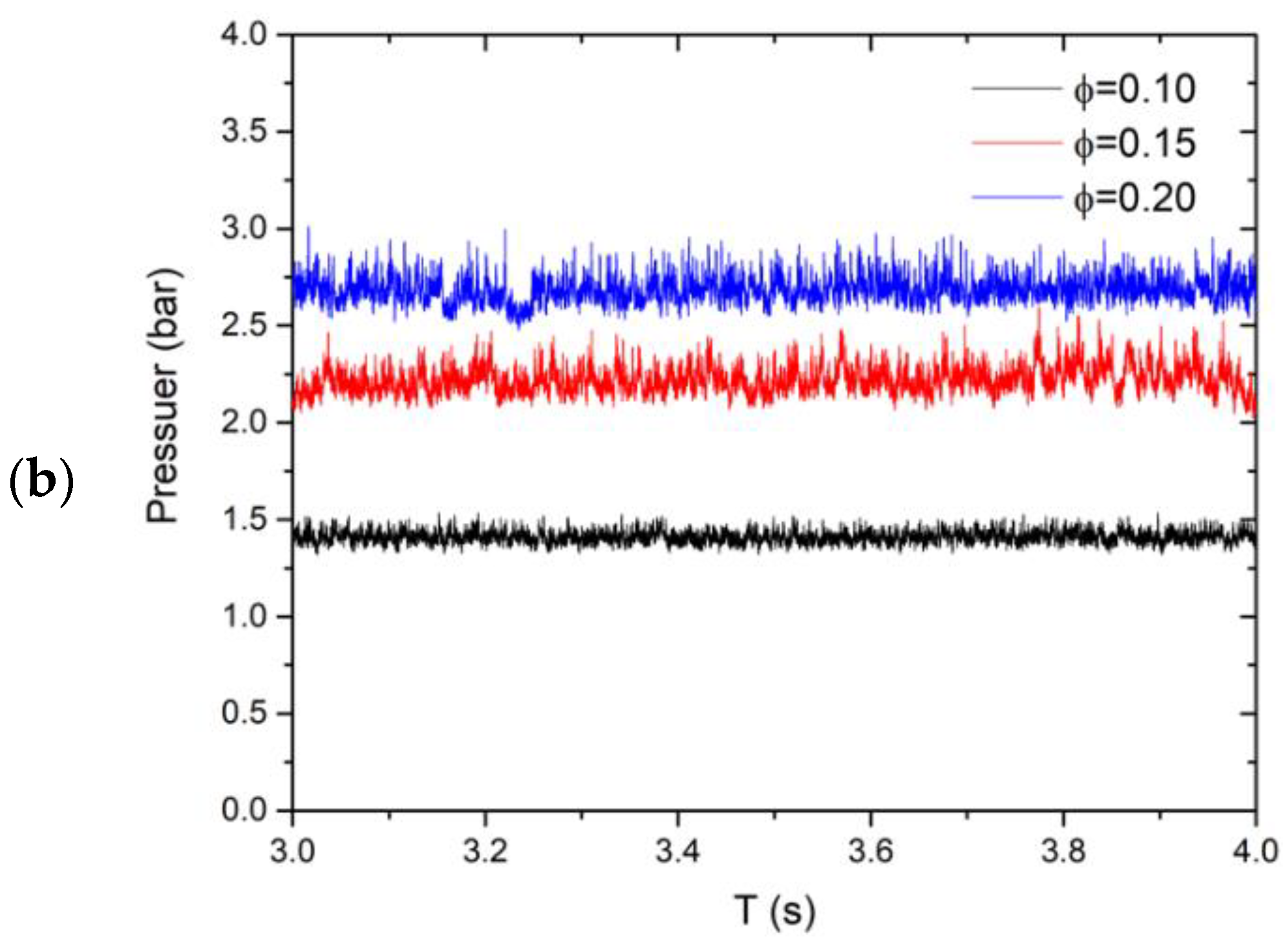
3.1. Pressure Characteristics of Scramjet

Figure 3 shows the static pressure measured along the scramjet combustor for various equivalence ratios. Due to the fluctuation of data, the error bar of the data is provided by calculating the standard deviation.
S = 1 n ( x i x ¯ ) 2 n 1
The combustion pressure increased with the increasing equivalence ratio. In the case of equivalence ratio φ = 0.10, the pressure in the combustion chamber did not increase significantly. When the equivalence ratio reached 0.15, the pressure in the combustion chamber increased obviously. When the equivalence ratio increased to 0.20, the increase in the combustion heat release reached a critical state. At the same time, the backpressure in the combustor increased the pressure in the front of the fuel jet.
It also can be seen that the high-frequency pressure was clearly in front of the fuel jet, as shown in Figure 4. The pressure history had a similar trend with equivalent ratios of 0.1 and 0.15. After the equivalent ratio reached 0.2, the pressure at the measuring point increased significantly, which presented an unstable state of high oscillation.

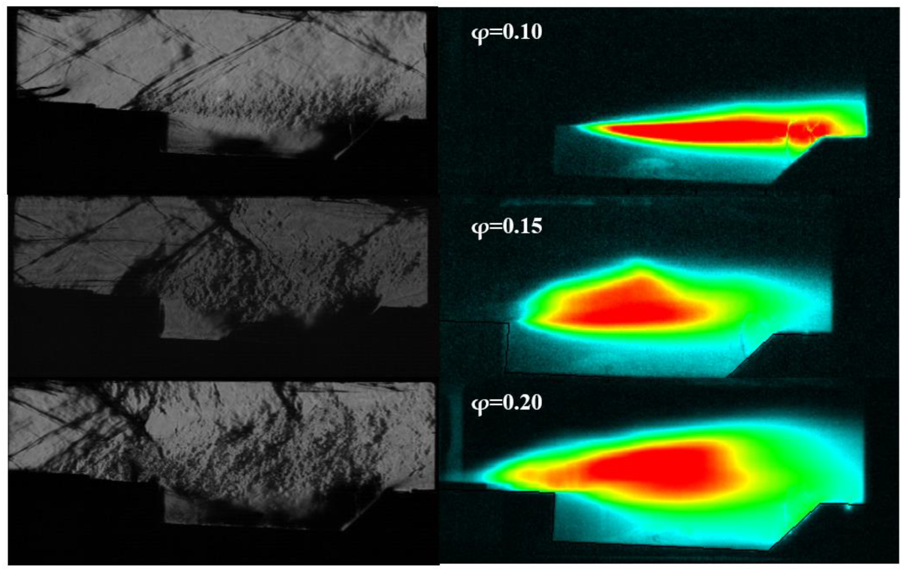
3.2. Flow and Combustion Modes in Combustor

Flame CH* chemiluminescence images were employed to analyze the flame structure and mode with different equivalence ratio conditions in a scramjet combustor. The flow and combustion structure in the combustor can be seen intuitively from schlieren and averaged CH* chemiluminescence images in Figure 5. The mean images of CH* chemiluminescence on the right of Figure 5. were obtained by processing the average grayscale of 2000 transient images. As shown in the schlieren images, the shockwave in the combustor moved upstream with the increase in the equivalence ratio. Under the conditions of equivalence ratios 0.1 and 0.15, the precombustion shockwave was stable in the downstream of the fuel jet. After the equivalence ratio reached 0.2, the shockwave stable position obviously moved forward to the upstream of the fuel jet.
In addition, when the equivalence ratio was 0.1, there was no “X”-type shockwave in the combustor, and the flame stabilized in the cavity shear layer, which was the shear layer stabilization mode. When the equivalent ratio increased to 0.15, an “X”-type shockwave appeared on the upside of the flame due to the increase in combustion heat release and backpressure, which made the flame present a jet wake stabilization mode. The peak area of the grayscale image was divided into two parts, namely, the flame stabilization area of the shear layer and the jet flame stabilization area above it. The flame stabilized at the shear layer, and the jet waked simultaneously. When the equivalence ratio increased to 0.2, the backpressure increased with the continually increasing heat release, and the “X”-type shockwave moved upstream to the front of the fuel jet. Therefore, the jet flame stabilization zone moved upstream to the front of the fuel jet. It formed a jet front flame stabilization mode where the jet flame stabilization zone was larger than the shear layer flame stabilization zone.

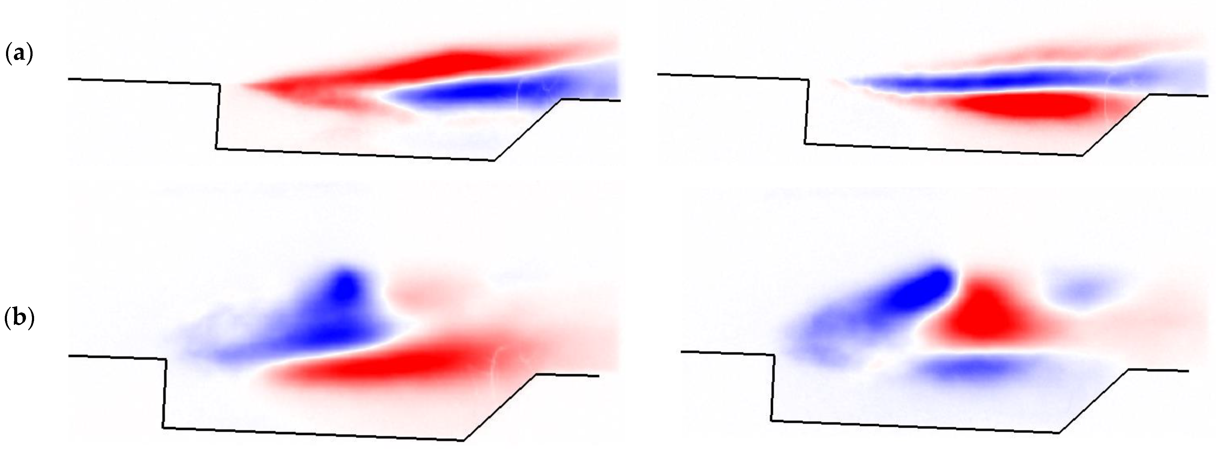
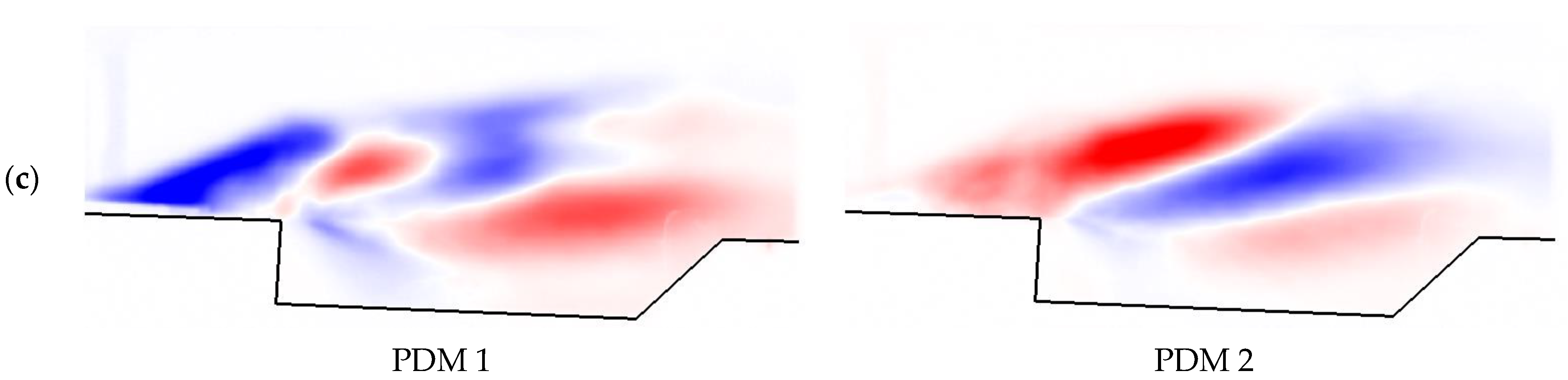
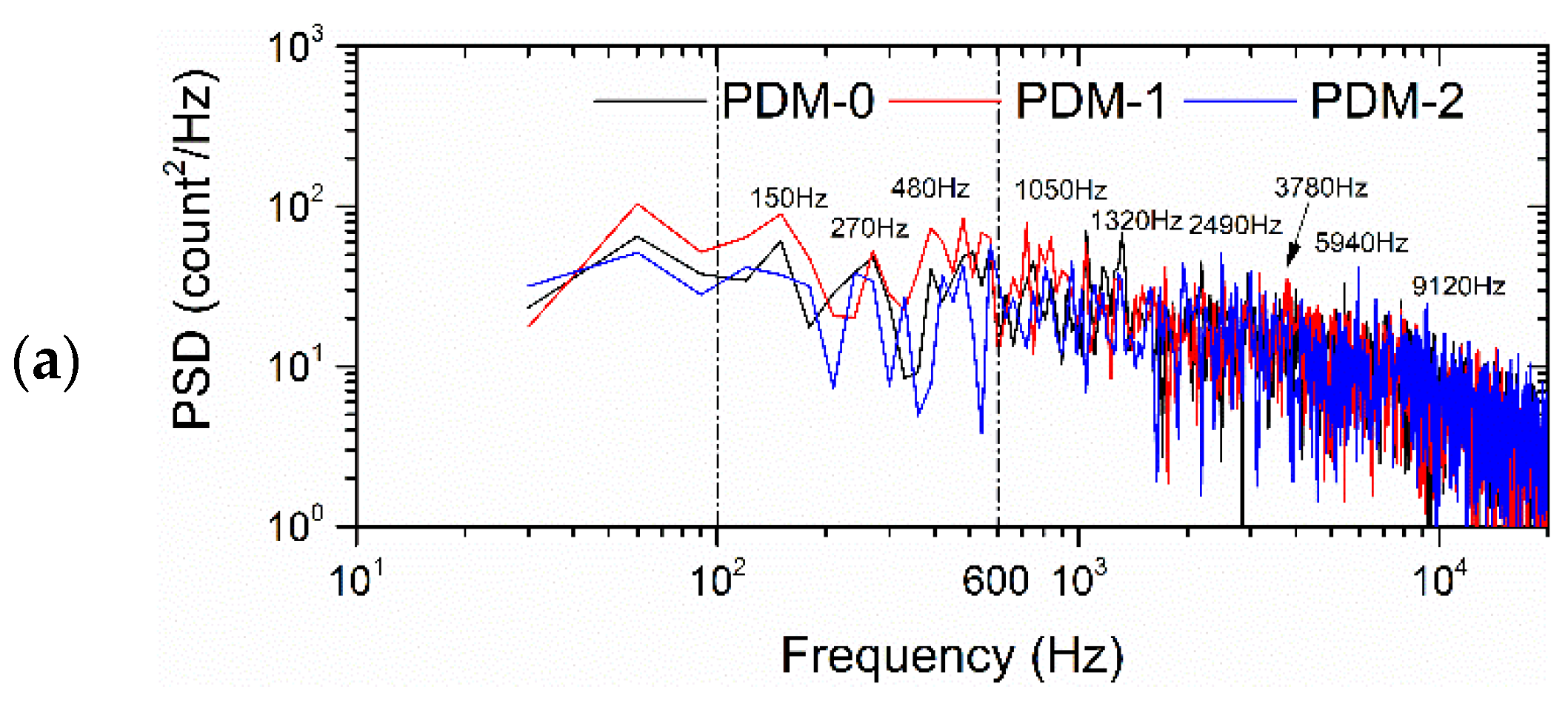
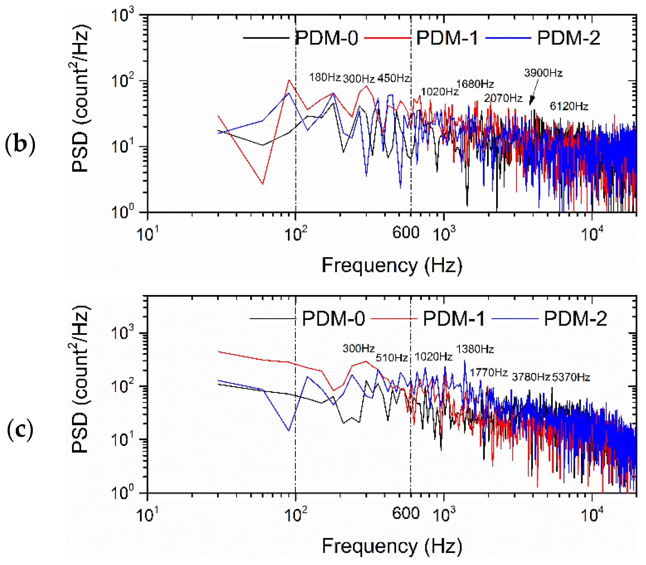
3.3. POD Mode (PDM) Characteristics of Flame

Combustion modes and instabilities were investigated based on time-resolved measurements of CH* chemiluminescence. Sequential images of CH* chemiluminescence were decomposed into the summation of PDMs, which were used to represent the dynamic process of the flame. The red and blue areas represent the areas where the flame oscillated significantly. The shades of red or blue represent the amplitude of the oscillation in different phases, which are indicated by positive and negative values. The first two PDMs were selected to characterize the stability. The PDM image in Figure 6 shows that the jet depth became larger with the increase in the injection equivalence ratio upstream of the cavity front edge. Furthermore, the flame oscillation area moved to the upper part of the cavity, which indicated that the leeward area formed by fuel injection created a favorable environment for flame generation.
The power spectral density (PSD) for the time coefficient was obtained using the fast Fourier transform (FFT) to investigate the characteristic frequencies. Figure 7 shows the PSD spectrum of PDM 0, 1, and 2 for φ = 0.10, 0.15, and 0.20. With the combustion mode transition from the shear layer mode to the jet front mode, the oscillation amplitude shows an increasing trend.
In the three spectra, the low frequency still occupies a high energy ratio, with peaks between 100 and 600 Hz. According to Lin et al. [36], the frequency spectra of pressure oscillations have distinct peaks between 100 and 400 Hz. Shinji Nakaya also reported that low-frequency peaks were between 100 and 500 Hz. The oscillations based on these frequencies were formed by injector–flame feedback, shock–flame acoustic feedback, and shock–flame acoustic convective feedback.
The difference in PSD frequencies was due to the difference in the stagnation temperature and Mach speed [23]. Under the condition of different equivalence ratios, the location and intensity of the shockwave in the flow field are different, which results in different stagnation temperatures in the combustor. When the equivalent ratio was 0.1, the flame stabilization mode was the shear layer, and the low frequencies of 150 Hz and 480 Hz were more prominent. With the increase in the equivalence ratio, the flame stabilization mode transitioned to the coexistence of jet flame stabilization and shear layer flame stabilization. Furthermore, the frequency spectrum appeared and gradually increased to 300 Hz, while the dominant frequencies near 150 Hz and 480 Hz decreased or even disappeared. Therefore, we believe that the jet flame stabilization mode was the main reason for the 300 Hz dominant frequency. There were also several high-frequency peaks of more than 1000 Hz observed in the spectra, which were thought to be caused by turbulent structures. However, more evidence may be needed to support this conclusion. Further investigation is required to find the cause of high-frequency oscillation [23].

4. Discussion

Instability combustion behaviors in a scramjet were investigated in a scramjet model with an ethylene injection system upstream of the cavity. The single cavity was employed as a flame holder at Ma 2.5. The technologies of high-framerate (HFR) CH* chemiluminescence images, schlieren, and high-frequency pressure sensors were adopted to observe flow and combustion behavior.
The supersonic combustion in the scramjet was divided into three modes according to different equivalent ratios. These are the cavity shear layer mode, the jet wake mode, and the jet front mode. Compared with earlier research, we found that the jet front mode is a new combustion mode that can be defined. It is formed because the fuel jet is closer to the front edge of the cavity (10 mm) compared with being far from the front edge of the cavity or at the bottom of the cavity in earlier research.
Shockwaves can provide reliable flow conditions for the flame-anchored position. Three different shockwaves at three selected equivalent ratios were observed in the combustor using schlieren images, which explained the formation of three combustion modes.
The instabilities in combustion were investigated based on time-resolved measurements of CH* chemiluminescence. The flame oscillation area moved to the upper side of the cavity and then moved to the front of the fuel jet with the increase in the injection equivalence ratio. This indicated that the jet depth became larger, and the leeward area formed by the fuel injection created a favorable environment for flame generation.
Low-frequency peaks were observed using PSD between 100 and 600 Hz, and the low frequency was formed by injector–flame feedback, shock–flame acoustic feedback, and shock–flame acoustic convective feedback.

5. Conclusions

Directly connected scramjet experiments were carried out to investigate the combustion characteristics. The single cavity was employed as a flame holder. Three typical combustion modes were classified by distinguishing averaged CH* chemiluminescence images of three ethylene fuel jet equivalence ratios. The reason for the formation was explained using schlieren images and pressure characteristics. PDMs were determined using the POD of flame CH* chemiluminescence sequential images. There were large peaks in the frequency range of 100–600 Hz for the three typical stabilized combustion modes. The cause of the high-frequency oscillation will be investigated further. The formation process of the three modes will be discussed next.

Author Contributions

Conceptualization, H.G. and Y.M.; methodology, Y.M.; writing—original draft preparation, Y.M.; writing—editing, W.S. and R.Z.; writing—review, F.C. All authors have read and agreed to the published version of the manuscript.

Funding

This research was funded by the Natural Science Foundation of Chongqing, China, grant number cstc2021jcyj-msxmX1118; the National Natural Science Foundation of China, grant number 11772342; and the Shanghai Post-Doctoral Excellence Program, grant number 2020251.

Data Availability Statement

Data available on request from the authors.

Acknowledgments

Thanks to the laboratory engineers for their support in completing the experiment. Thanks to Li for the English polishing work performed on the article.

Conflicts of Interest

The authors declare no conflict of interest.

References

  1. Billig, F.S. Research on supersonic combustion. J. Propuls. Power 1993, 9, 499–514. [Google Scholar] [CrossRef]
  2. Ju, Y.; Sun, W. Plasma assisted combustion: Dynamics and chemistry. Prog. Energy Combust. Sci. 2015, 48, 21–83. [Google Scholar] [CrossRef]
  3. Reddy, P.N.; Venkatasubbaiah, K. Numerical Investigations on Development of Scramjet Combustor. J. Aerosp. Eng. 2015, 28, 04014120. [Google Scholar] [CrossRef]
  4. Meng, Y.; Gu, H.; Zhang, X. Experimental Study of Kerosene Ignition and Flame Stabilization in a Supersonic Combustor. Int. J. Turbo Jet-Engines 2019, 39, 403–410. [Google Scholar] [CrossRef]
  5. He, Z.; Wang, H.; Li, F.; Tian, Y.; Wan, M.; Zhu, J. Effect of Fuel-Injection Distance and Cavity Rear-Wall Height on the Flameholding Characteristics in a Mach 2.52 Supersonic Flow. Aerospace 2022, 9, 566. [Google Scholar] [CrossRef]
  6. Dooley, S.; Won, S.H.; Heyne, J.; Farouk, T.I.; Ju, Y.; Dryer, F.L.; Kumar, K.; Hui, X.; Sung, C.-J.; Wang, H.; et al. The experimental evaluation of a methodology for surrogate fuel formulation to emulate gas phase combustion kinetic phenomena. Combust. Flame 2012, 159, 1444–1466. [Google Scholar] [CrossRef]
  7. Zhu, S.-H.; Xu, X. Experimental Study on Flame Transition in a Two-Stage Struts Dual-Mode Scramjet. J. Aerosp. Eng. 2017, 30, 06017002. [Google Scholar] [CrossRef]
  8. Aradag, S.; Gelisli, K.A.; Yaldir, E.C. Effects of Active and Passive Control Techniques on Mach 1.5 Cavity Flow Dynamics. Int. J. Aerosp. Eng. 2017, 2017, 8253264. [Google Scholar] [CrossRef]
  9. Vinogradov, V.; Grachev, V.; Petrov, M.; Shikhman, I. Experimental investigation of a 2-D dual mode scramjet with hydrogenfuel at Mach 4–6. In Proceedings of the 2nd International Aerospace Planes Conference, Orlando, FL, USA, 29–31 October 1990. [Google Scholar] [CrossRef]
  10. Ben-Yakar, A.; Hanson, R. Cavity flameholders for ignition and flame stabilization in scramjets—Review and experimental study. In Proceedings of the 34th AIAA/ASME/SAE/ASEE Joint Propulsion Conference and Exhibit, Cleveland, OH, USA, 13–15 July 1998. [Google Scholar] [CrossRef]
  11. Meng, Y.; Gu, H.; Zhuang, J.; Sun, W.; Gao, Z.; Lian, H.; Yue, L.; Chang, X. Experimental study of mode transition characteristics of a cavity-based scramjet combustor during acceleration. Aerosp. Sci. Technol. 2019, 93, 105316. [Google Scholar] [CrossRef] [Green Version]
  12. Yuan, Y.; Zhang, T.; Yao, W.; Fan, X.; Zhang, P. Characterization of flame stabilization modes in an ethylene-fueled supersonic combustor using time-resolved CH* chemiluminescence. Proc. Combust. Inst. 2017, 36, 2919–2925. [Google Scholar] [CrossRef] [Green Version]
  13. Meng, Y.; Gu, H.; Chen, F. Influence of Plasma on the Combustion Mode in a Scramjet. Aerospace 2022, 9, 73. [Google Scholar] [CrossRef]
  14. Vanyai, T.; Landsberg, W.O.; McIntyre, T.J.; Veeraragavan, A. OH visualization of ethylene combustion modes in the exhaust of a fundamental, supersonic combustor. Combust. Flame 2021, 226, 143–155. [Google Scholar] [CrossRef]
  15. Landsberg, W.O.; Vanyai, T.; McIntyre, T.J.; Veeraragavan, A. Dual/scram-mode combustion limits of ethylene and surrogate endothermically-cracked hydrocarbon fuels at Mach 8 equivalent high-enthalpy conditions. Proc. Combust. Inst. 2021, 38, 3835–3843. [Google Scholar] [CrossRef]
  16. Liu, X.; Cai, Z.; Tong, Y.; Zheng, H. Investigation of transient ignition process in a cavity based scramjet combustor using combined ethylene injectors. Acta Astronaut. 2017, 137, 1–7. [Google Scholar] [CrossRef]
  17. Cao, D.; Brod, H.E.; Yokev, N.; Michaels, D. Flame stabilization and local combustion modes in a cavity-based scramjet using different fuel injection schemes. Combust. Flame 2021, 233, 111562. [Google Scholar] [CrossRef]
  18. Zhu, S.; Xu, X.; Yang, Q.; Jin, Y. Intermittent back-flash phenomenon of supersonic combustion in the staged-strut scramjet engine. Aerosp. Sci. Technol. 2018, 79, 70–74. [Google Scholar] [CrossRef]
  19. Potturi, A.S.; Edwards, J.R. Large-eddy/Reynolds-averaged Navier–Stokes simulation of cavity-stabilized ethylene combustion. Combust. Flame 2015, 162, 1176–1192. [Google Scholar] [CrossRef]
  20. Tian, Y.; Yang, S.; Le, J.; Su, T.; Yue, M.; Zhong, F.; Tian, X. Investigation of combustion and flame stabilization modes in a hydrogen fueled scramjet combustor. Int. J. Hydrog. Energy 2016, 41, 19218–19230. [Google Scholar] [CrossRef]
  21. Wang, Z.; Cai, Z.; Sun, M.; Wang, H.; Zhang, Y. Large Eddy Simulation of the flame stabilization process in a scramjet combustor with rearwall-expansion cavity. Int. J. Hydrog. Energy 2016, 41, 19278–19288. [Google Scholar] [CrossRef]
  22. Micka, D.J.; Driscoll, J.F. Combustion characteristics of a dual-mode scramjet combustor with cavity flameholder. Proc. Combust. Inst. 2009, 32, 2397–2404. [Google Scholar] [CrossRef]
  23. Nakaya, S.; Kinoshita, R.; Lee, J.; Ishikawa, H.; Tsue, M. Analysis of supersonic combustion characteristics of ethylene/methane fuel mixture on high-speed measurements of CH* chemiluminescence. Proc. Combust. Inst. 2019, 37, 3749–3756. [Google Scholar] [CrossRef]
  24. Wang, H.; Wang, Z.; Sun, M.; Wu, H. Combustion modes of hydrogen jet combustion in a cavity-based supersonic combustor. Int. J. Hydrog. Energy 2013, 38, 12078–12089. [Google Scholar] [CrossRef]
  25. Feng, R.; Zhu, J.; Wang, Z.; Zhang, F.; Ban, Y.; Zhao, G.; Tian, Y.; Wang, C.; Wang, H.; Cai, Z.; et al. Suppression of combustion mode transitions in a hydrogen-fueled scramjet combustor by a multi-channel gliding arc plasma. Combust. Flame 2022, 237, 111843. [Google Scholar] [CrossRef]
  26. Wang, T.; Li, G.; Yang, Y.; Wang, Z.; Cai, Z.; Sun, M. Combustion modes periodical transition in a hydrogen-fueled scramjet combustor with rear-wall-expansion cavity flameholder. Int. J. Hydrog. Energy 2020, 45, 3209–3215. [Google Scholar] [CrossRef]
  27. Zhu, S.; Xu, X.; Ji, P. Flame Stabilization and Propagation in Dual-Mode Scramjet with Staged-Strut Injectors. AIAA J. 2017, 55, 171–179. [Google Scholar] [CrossRef]
  28. Yan, Z.; Shaohua, Z.; Bing, C.; Xu, X. Hysteresis of mode transition in a dual-struts based scramjet. Acta Astronaut. 2016, 128, 147–159. [Google Scholar] [CrossRef]
  29. Zhang, J.; Chang, J.; Ma, J.; Zhang, C.; Bao, W. Investigation of flame establishment and stabilization mechanism in a kerosene fueled supersonic combustor equipped with a thin strut. Aerosp. Sci. Technol. 2017, 70, 152–160. [Google Scholar] [CrossRef]
  30. Masumoto, R.; Tomioka, S.; Kudo, K.; Murakami, A.; Kato, K.; Yamasaki, H. Experimental Study on Combustion Modes in a Supersonic Combustor. J. Propuls. Power 2011, 27, 346–355. [Google Scholar] [CrossRef]
  31. Aguilera, C.; Yu, K.H. Scramjet to ramjet transition in a dual-mode combustor with fin-guided injection. Proc. Combust. Inst. 2017, 36, 2911–2918. [Google Scholar] [CrossRef]
  32. Fotia, M.L.; Driscoll, J.F. Ram-Scram Transition and Flame/Shock-Train Interactions in a Model Scramjet Experiment. J. Propuls. Power 2013, 29, 261–273. [Google Scholar] [CrossRef]
  33. Choi, J.Y.; Yang, V.; Fuhua, M.; Won, S.H.; Jeung, I.S. DES combustion modeling of a scramjet combustor. AIAA Pap. 2006, 5097, 2006. [Google Scholar]
  34. Li, J.; Ma, F.; Yang, V.; Lin, K.-C.; Jackson, T. A Comprehensive Study of Combustion Oscillations in a Hydrocarbon-Fueled Scramjet Engine. In Proceedings of the 45th AIAA Aerospace Sciences Meeting and Exhibit, Reno, Nevada, 8–11 January 2007. [Google Scholar] [CrossRef]
  35. Ma, F.; Li, J.; Yang, V.; Lin, K.-C.; Jackson, T. Thermoacoustic Flow Instability in a Scramjet Combustor. In Proceedings of the 41st AIAA/ASME/SAE/ASEE Joint Propulsion Conference & Exhibit, Tucson, Arizona, 10–13 July 2005. [Google Scholar] [CrossRef]
  36. Lin, K.-C.; Jackson, K.; Behdadnia, R.; Jackson, T.A.; Ma, F.; Yang, V. Acoustic Characterization of an Ethylene-Fueled Scramjet Combustor with a Cavity Flameholder. J. Propuls. Power 2010, 26, 1161–1170. [Google Scholar] [CrossRef] [Green Version]
  37. Allison, P.M.; Frederickson, K.; Kirik, J.W.; Rockwell, R.D.; Lempert, W.R.; Sutton, J.A. Investigation of supersonic combustion dynamics via 50 kHz CH* chemiluminescence imaging. Proc. Combust. Inst. 2017, 36, 2849–2856. [Google Scholar] [CrossRef]
  38. Li, X.; Lei, Q.; Zhao, X.; Fan, W.; Chen, S.; Chen, L.; Tian, Y.; Zhou, Q. Combustion Characteristics of a Supersonic Combustor with a Large Cavity Length-to-Depth Ratio. Aerospace 2022, 9, 214. [Google Scholar] [CrossRef]
Figure 1. Scramjet experimental system: (a) system diagram; (b) scramjet combustor model and measurements points.
Aerospace 09 00826 g001
Figure 2. The cavity and fuel jet structure.
Aerospace 09 00826 g002
Figure 3. Static pressure for various equivalence ratios along the scramjet combustor.
Aerospace 09 00826 g003
Figure 4. Pressure history of (a) points CH02 (front of fuel jet) and (b) CH03 (posterior edge of cavity).
Aerospace 09 00826 g004aAerospace 09 00826 g004b
Figure 5. Schlieren and pseudo-color images of averaged flame CH* chemiluminescence.
Aerospace 09 00826 g005
Figure 6. The first two PDMs of flame CH* chemiluminescence. (a) φ = 0.1, (b) φ = 0.15, (c) φ = 0.2.
Aerospace 09 00826 g006aAerospace 09 00826 g006b
Figure 7. Power spectrum density of FFT for PDM coefficients. (a) φ = 0.1, (b) φ = 0.15, (c) φ = 0.2.
Aerospace 09 00826 g007aAerospace 09 00826 g007b
Table 1. Equivalence ratios for various flame stabilization modes.
CasesEquivalence Ratio φCombustion Stabilization Mode
10.10Cavity shear layer
20.15Jet wake
30.20Jet front
Publisher’s Note: MDPI stays neutral with regard to jurisdictional claims in published maps and institutional affiliations.

