Article

Optimization Design of the NUAA-PTRE: A New Pre-Cooled Turbine Engine Adapting to 0~5 Mach Number

1
College of Energy and Power Engineering, Nanjing University of Aeronautics and Astronautics, Nanjing 210016, China
2
Beijing Power Machinery Research Institute, Beijing 100074, China
3
Xi’an Yuanhang Vacuum Brazing Technology Co., Ltd., Xi’an 710200, China
*
Authors to whom correspondence should be addressed.
Aerospace 2023, 10(2), 185; https://doi.org/10.3390/aerospace10020185
Submission received: 10 December 2022 / Revised: 19 January 2023 / Accepted: 12 February 2023 / Published: 15 February 2023
(This article belongs to the Special Issue Advances in Hypersonic Aircraft Propulsion Technology)

Abstract

:
A model of a NUAA-PTRE pre-cooled air turbine engine was established. The design point parameters of the engine were optimized, including the pressure ratio, air flow rate of the compressor, efficiency, throat area, and efficiency of the turbine. The air flow rate at the engine operating point was 142.73 kg/s. High performance of the key components under a wide range of working conditions was realized after optimization. To achieve the indicators of the overall scheme, adaptability studies of key components were conducted. A three-stage variable geometry design was applied to the inlet. The pre-cooler was optimized with a power-to-weight ratio of over 100 kW/kg and a compactness of 278 m2/m3. The built-in rocket gas generator and dual-component injector were developed, and the combustion and heat transfer processes were simulated. The overall optimization design of the NUAA-PTRE and the adaptive design of the components were completed, and high performance of the engine in a wide range of flight conditions at Ma 0~5 and altitude 0~25 km was achieved.

1. Introduction

In order to meet the demand for full-speed range flight of aircraft, various forms of combined power have received a lot of attention. The working range of the general aviation turbine engine is at a Mach number of 0~3, the optimal working range of the sub-scramjet engine is at Mach 2~6, and the working Mach number of the scramjet engine can reach more than 5 [1]. The combined-cycle engine combines different types of engines, thereby broadening the operating range. Turbine-based combined-cycle (TBCC) engines [2], rocket-based combined-cycle (RBCC) engines [3,4,5], pulse detonation engines [6,7], airbreathing combined-cycle engines [8,9,10], etc., have been produced [11].
In the 1950s, the United States first proposed pre-cooled airbreathing combined-cycle engines [12]. Since then, pre-cooled airbreathing combined-cycle engines have made continuous progress under the research of various countries. In the late 1980s, the Institute of Space and Astronautical Science (ISAS) began to develop an air turbo ramjet of expander cycle (ATREX) engine with an expansion cycle. In 1995, a sea-level static test was conducted on the ATREX-500 model test machine. Due to the use of liquid hydrogen for pre-cooling, the air flow of the engine increased, and the corrected speed and pressure ratio of the fan increased; thereby, the thrust and specific impulse increased by 1.8 times and 1.25 times, respectively [13]. After that, the Japan Aerospace Exploration Agency (JAXA) conducted research on the pre-cooled turbojet engine (PCTJ) on the basis of the ATREX research. The program produced a model prototype, named the S-engine, and completed a flight demonstration test in 2010. In addition, considering the safety and stability issues of hydrogen fuel, a performance analysis of various other fuel coolants was also carried out to find a better alternative fuel and coolant [14].
The synergetic airbreathing rocket engine (SABRE), developed by British Reaction Engine Limited, is a typical pre-cooling combined-cycle power engine. Since its inception, the scheme has received extensive attention due to its compact and efficient characteristics and outstanding performance advantages [15]. For the first time, the closed cycle of the intermediate medium helium was innovatively introduced, which solved the problem of hydrogen embrittlement caused by the direct pre-cooling of liquid hydrogen. Based on this engine, a number of advanced aerospace power vehicles have been proposed, such as the aerospace aircraft SKYLON [16,17], which is designed for reusable round-trip transportation, as well as the SCIMITAR scheme, which pays more attention to endurance and is aimed at hypersonic civil aviation aircraft [18].
The United States is also developing hypersonic aircraft and full-speed-range propulsion systems, in which the combined power based on the turbine cycle also faces the problem of pre-cooling under high temperature. In the 1950s, the United States proposed the concept of mass injection and pre-compressor cooling (MIPCC). The Defense Advanced Research Projects Agency (DARPA) also proposed the advanced full-range engine (AFRE) project to develop and demonstrate a new aircraft propulsion system to achieve operation in the full speed range, from low speed when taking-off to hypersonic flight [19,20].
In recent years, various institutes have carried out research on the modeling and performance calculation of component-level research on pre-cooling combined engines. This provides a theoretical basis for further engine tests. Yiming Chen et al. [21] used the logarithmic mean temperature difference (LMTD) methodology to model and calculate the annular micro-pipe pre-cooler of the pre-cooled engine at Mach 4. Under a given situation, the size parameters of the micro-pipe can be determined by iterative solution, including the inner and outer diameter of the pipe, the axial length, the number of micro-pipe modules, and the number of pipe rows. Xuanfei Yu et al. [22] developed a numerical model of the fuel indirect pre-cooled cycles (IPC), performed numerical analysis, defined the pre-cooling compression sub-cycle, and defined a new efficiency figure, revealing the performance advantages of the fuel indirect pre-cooled cycles to the Brayton cycle. Z.Y. Hou et al. [23] used a stainless-steel strut with an active cooling structure for thermal protection in a severe combustor environment in a rocket-based combined cycle (RBCC) engine.
For the overall scheme of the new pre-cooled combined-cycle propulsion, researchers have proposed many innovative high-performance overall thermal cycles and corresponding engine schemes and have conducted theoretical modeling and performance analysis. Xiaofeng Ma et al. [24] proposed a supercritical CO2 recuperative Brayton cycle for hypersonic vehicles to meet the high air-inlet temperature, engine-wall temperature, and electrical–energy demand. Wei Zhao et al. [25] proposed a novel pre-cooled and fuel-rich pre-burned mixed-flow turbofan (PFPMT) cycle, established the engine cycle model, and carried out performance analysis. The results show that the engine has a higher specific impulse and higher thrust ratio than the ATR GG engine. V. Fernández-Villacé et al. [26] established a numerical model of the combined power of an air turbo-rocket expander and a dual-mode ramjet. After the Mach number reached 4.5, the operation transformed from the air turbine rocket mode to the ramjet mode. I. Rodríguez-Miranda et al. [27] assessed the capabilities of the air-turbo-rocket expander through a complete theoretical study of the thermodynamic cycle and identified dimensionless parameters in the cycle and performance analysis. A numerical model based on differential algebraic equations was developed using an object-oriented simulation tool, and the expander cycle was optimized. Helen Webber et al. [28] found that the maximum irreversible loss in the cycle comes from the heat transfer of the pre-cooler. If the heat transfer coefficient of the air side of the pre-cooler can be increased, the cycle efficiency can be further improved. Jianqiang Zhang et al. [29] conducted an efficiency calculation and cycle optimization for the SABRE engine, established an engine component level model, conducted an efficiency analysis, and proposed methods to improve cycle efficiency. Pengcheng Dong et al. [4] put forward the hypersonic pre-cooled combined-cycle engine (HPCCE), whose most remarkable feature is multi-cycle coupling. This mechanism is studied via engine cycle analysis with enthalpy–entropy relations. Rui Gu et al. [30] proposed a novel experimental facility to evaluate the internal thrust performance of the RBCC engine. Zifei Ji et al. [31] presented a configuration for the rotating detonative airbreathing combined-cycle engine with compatibility between turbomachinery and rotating detonation.
With research institutions exploring the pre-cooled air turbo combined power, the theoretical research of each pre-cooling scheme has been demonstrated. Different engine numerical models and calculation methods were established by the researchers, and beneficial exploration on the pre-cooling combined-cycle power under different thermal cycle modes were conducted. Consequently, the engine thermodynamic cycle has been continuously optimized, and the cycle efficiency, specific impulse thrust, and other key overall performances of the engine were optimized, solving the match of flow rates and efficient heat transfer problems. The key components and key technologies have been studied in depth, including the variable geometry inlet [32], micro-pipe pre-cooler [33], etc., in which numerical simulation and optimization have been conducted. Both the SABRE engine in Britain and the ATREX engine in Japan have undergone a series of ground tests and flight tests of small-scale models. The feasibility of the scheme has been verified from different component characteristics and engine actual flight characteristics, and the expected test results have been obtained. In addition, the research team also conducted in-depth experimental research on heat transfer and the flow mechanism, and they found the flow and heat transfer characteristics of fuel in the boiling state [34], which provides a reliable theoretical basis for engine design and control.
On the basis of the previous research on the airbreathing pre-cooled combined-cycle engine, our research group proposed a new type of air turbo rocket engine, the NUAA-PTRE (Nanjing University of Aeronautics and Astronautics, pre-cooled turbo rocket engine), using endothermic hydrocarbon fuel as the coolant and fuel. The oxidant is liquid oxygen, and endothermic hydrocarbon fuel is a two-component mixture of 58.92% n-decane and 41.08% 1,2,4 trimethyl cyclohexane. In this paper, the structure and thermodynamic cycle analysis of the new air turbine rocket engine is described, and the simulation modeling and numerical calculation of the engine was carried out. Under the common working conditions, the engine cycle was iteratively calculated, and the performance characteristics of each component and the overall engine were obtained. The reliability of the calculation method was verified by comparing it with the test data of the PATR air turbo engine with a similar structure. Then, the key design parameters of the core engine were optimized. The most outstanding feature of the NUAA-PTRE is that it can continuously maintain high performance at a wide range of speeds and in a wide range of airspace. The key technologies of key components were optimized to meet the overall goal. First, a three-stage variable geometry intake port was realized to adapt to the complex intake conditions and to reduce the intake loss. Second, an annular microchannel heat exchanger was designed to achieve efficient and compact heat transfer, as well as to significantly reduce the inlet temperature at a high Mach number. Third, a built-in wide range variable flow rocket generator was designed to effectively deal with the complex gas conditions caused by the different cracking degrees of hydrocarbon fuel at different temperatures. Through CFD analysis, it was found that there was a recirculation zone at the head of the combustion chamber, which provided an important reference for thermal protection. The research and development of these technologies has provided a guarantee for the high performance of the engine under a wide speed range of Ma 0~5 and a wide altitude range of 0~25 km.

2. Engine Model Establishment of the NUAA-PTRE

2.1. Analysis of the Engine Structure and Thermal Cycle

The NUAA-PTRE is a tandem pre-cooled turbo rocket combined-cycle engine. Compared with the traditional combined-cycle engine, the NUAA-PTRE operates in the mode of the turbofan/ram, working together, and it is simpler in structure. The structure of the NUAA-PTRE consists of an integrated adaptive variable geometry intake/pre-cooler, compressor, turbine, mixer/flame stabilizer, combustion chamber, nozzle, rich-fuel gas generator, pump system, gearbox, distributor, etc. Its structure is shown in Figure 1.
The air is compressed isentropically in the inlet (0–1), then heat is released isobarically in the pre-cooler (1–2). The air is compressed isentropically in the compressor (2–3) and heated isobarically in the precombustion chamber (3–4), and it expands isentropically in the turbine (4–5). Air is heated isobarically in the mixer (5–6), and then it is heated isobarically in the combustion chamber (6–7). Air expands isentropically in the nozzle (7–9), and finally, heat is released isobarically in the atmospheric environment (9–0). The thermal cycle diagram of the air circuit is shown in Figure 2. It can be seen from Figure 2 that the turbine inlet and combustion chamber inlet have the highest temperature, which is the key part of the thermal protection. As is shown in Figure 2, the air temperature in the pre-cooler significantly decreases, reducing the temperature of the engine thermal cycle, especially the high temperature at the turbine inlet and the combustion chamber inlet, which is conducive to the stable operation of the engine. This reduces the requirements for material selection, leaving room for growth in other performance areas, such as the engine economy.

2.2. Engine Modeling and Calculation

According to the characteristics of the NUAA-PTRE, some assumptions were made, as follows [35]:
(1)
The gas generator and combustion chamber are in thermochemical equilibrium, which means there is no other heat exchange process, except combustion chemical reaction;
(2)
The gas flowing through the nozzle and turbine is frozen flow.
(3)
The airflow along the inner channel is one-dimensional steady flow;
(4)
The variable specific heat calculation is adopted. That is, the change in specific heat ratio and specific heat capacity with the temperature of the air flowing through the inlet and compressor, and gas flowing through the turbine and nozzle, is considered.
(5)
It is considered that the outlet parameters of the gas generator are the same as those of the turbine inlet.
(6)
It is considered that there is no heat exchange loss in the pre-cooler, which means that the heat exchange process in the precooler is an ideal cycle.

2.3. Calculation and Solution Process

Common working conditions are assumed as follows:
(1)
Compressor speed is equal to turbine speed: n k = n t .
(2)
The pressure at the junction between two adjacent components is the same, including the introduced pre-cooler, which has been reflected in the component-level modeling process in this paper.
(3)
The power of the compressor and turbine is balanced: η m = L c ˙ / L t ˙ .
(4)
Heat exchange in the pre-cooling device is balanced:
η 2 ( T a 2 , in T ox , in ) = T ox , out T ox , in ;
(5)
The flow is continuous. The total gas flow is the sum of the air flow, gas flow, and oxygen flow. The air flow is consistent with the flow in the compressor, which is q a . The gas fuel flow and oxygen flow are consistent with those in the generator as q f   and q o x , respectively, as is shown in the following formula:
q t o t = q a + q f + q o x

2.4. Iterative Solution Process

2.4.1. Solution of Design Point

After comprehensive judgment, appropriate compressor design parameters under standard operating conditions were preliminarily selected, consisting of the design pressure ratio, design efficiency, and design corrected flow. After determining the compressor design point, the turbine pressure drop ratio, π t , and turbine throat area, A t , should be adjusted iteratively. The iterative equations are the heat transfer balance in pre-cooler 2 and the power balance of compressor and turbine, so that the heat exchange efficiency of pre-cooler 2, η 2   , and turbine mechanical efficiency, η m , determine the turbine pressure ratio, π t   Finally, the turbine pressure ratio, π t , and the turbine throat area, A t , are determined when power equilibrium and mass flow continuity equations are satisfied.

2.4.2. Solution of Non-Design Point

The balance under non-design-point working conditions is achieved by changing the turbine pressure ratio, π t , and air total temperature at the outlet of pre-cooler 2,   T a 2 , out . The air temperature at the outlet of pre-cooler 2 and turbine pressure drop ratio should match each other and be adjusted iteratively, step by step, so as to finally make sure that the heat transfer efficiency of pre-cooler 2, η 2 , and mechanical efficiency, η m , fall within the allowable range of residual error; thus, the working point position of the non-design point can be determined.

3. Calculation Results and Analysis

3.1. Validation of the Model and Calculation Program

In order to verify the reliability of the performance calculation program, the performance parameters of PATR (pre-cooling air turbo rocket) engines were selected for preliminary comparison. The typical trajectory of the PATR engine is shown in Table 1 [36].
The thrust was nondimensionalized by the value of thrust on Mach 0 to compare the change trend. As is shown in Figure 3a, the calculated thrust of the NUAA-PTRE and PATR engine on the same trajectory was compared. It can be seen that, at a low Mach number, the results calculated by the NUAA-PTRE performance calculation program are basically consistent with the thrust trend of the PATR engine, while they are approximately five times greater in numerical value, determined by lager scale design of NUAA-PTRE. However, when the Mach number rises to 4, the NUAA-PTRE thrust increases, while the PATR engine thrust decreases, which is caused by the cracking of the endothermic hydrocarbon fuel in the pre-cooler of the NUAA-PTRE. It can be seen that the change trend of the NUAA-PTRE using normal fuel (i.e., no chemical heat sink) is similar to that of the PATR engine in the full speed domain, which proves that the engine performance calculation program of the NUAA-PTRE is reasonable and conforms to the performance law of engine operation.
As shown in Figure 3b, more dates between Mach 4 to Mach 5 were added to study the specifical cracking processes of endothermic hydrocarbon fuel. The thrust increased significantly when Mach number reached Mach 4.1 due to the increase in air flow caused by the decrease in temperature after precooling with cracking heat adsorption. When the Mach number is 4.1, the total temperature of air at the inlet of the pre-cooler 1 is 948.8 K, which just crossed the critical temperature for the cracking of endothermic hydrocarbon fuels, thus greatly increasing the degree of endothermic hydrocarbon fuel cracking.

3.2. Optimization and Selection of Design Point Parameters

Selecting and determining engine design point parameters is conducive to improving the working performance of the engine at the design point, taking into account the economy of engine operation. Furthermore, it can pre-consider the safety of the engine, reducing the difficulty with later research and improving feasibility.

3.2.1. Selection of the Air Flow and Precombustion Chamber Temperature

In this paper, the design point parameters were selected under the working conditions of a Mach number of 5 and an altitude of 25 km, which are to meet the requirements of high-speed cruise. The design air flow datum at a Mach number of 0 and altitude of 0 km (sea-level static state) was selected as 125 kg/s to meet the thrust requirements of take-off at sea level. Based on the performance data of a general compressor, the actual flow rate of air through the compressor at high altitude was 142.730 kg/s.
The higher the temperature of the precombustion chamber, the stronger the turbine’s ability to work, indicating that the core engine can be driven with a lower gas flow, which will improve the specific impulse performance of the engine. On the other hand, the lower the gas flow, the lower the coolant flow through the pre-cooler. The core problem with the NUAA-PTRE was the reliable pre-cooling of air at high Mach numbers of Ma 4–5. Endothermic hydrocarbon fuel was used to increase the cooling power. Finally, the precombustion chamber temperature was selected as 1600 K, which can basically meet specific impulse performance and reliable air-cooling needs at the same time.

3.2.2. Selection of the Design Pressure Ratio of the Compressor

The design pressure ratio of the compressor increased from 2.2 to 4.4; the thrust changed with the design pressure ratio almost linearly, as shown in Figure 4. As shown in Figure 4, the specific impulse decreased with the increase in design pressure ratio, and the change rate of specific impulse decreased as the design pressure ratio increased. At a low design pressure ratio, the specific impulse was greatly affected by its change.
As is shown in Figure 4, the total temperature at the outlet of the pre-cooler and at the outlet of the compressor decreased with the increase in the design pressure ratio, and the total temperature at the outlet of the pre-cooler was more sensitive to the change in the design pressure ratio. The outlet temperature must not be too high due to the thermal load intensity of the materials and the design level of the engine. The design pressure ratio must not be too low to guarantee that the total outlet temperature of the compressor is less than 950 K. The NUAA-PTRE needs to consider the economy comprehensively, so the specific impulse performance of the engine was given priority, which required the design pressure ratio to be lower. At the same time, in order to control the total temperature at the outlet, the design pressure ratio should not be too low. After comprehensive consideration, the compressor design pressure ratio was determined to be 2.8.

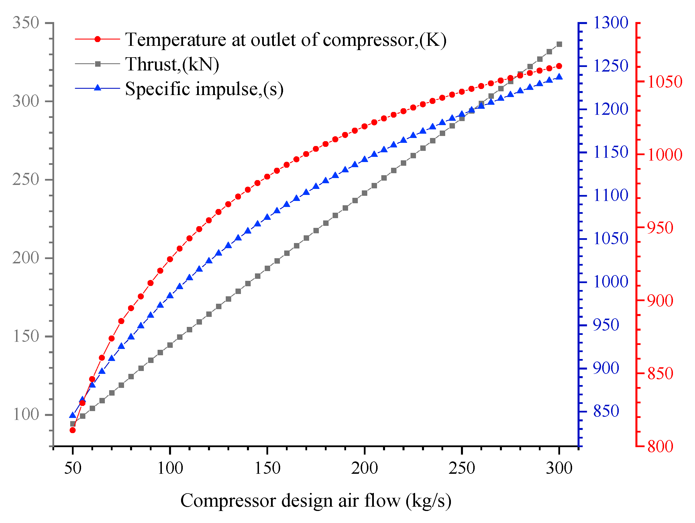
3.2.3. Selection of the Design Flow of the Compressor

Figure 5 shows that the engine thrust and specific impulse were positively correlated with the compressor design flow. The thrust was approximately linear with the compressor, while the change rate of the specific impulse with the increase in compressor design flow gradually decreased, from 845 s to 1245 s.
As is shown in Figure 5, the air total temperature at the outlet of the pre-cooler and the total temperature at the outlet of the compressor had similar variation trends, the total temperature at the outlet of the compressor increased with the compressor design flow, and the change rate decreased. If the economy is considered a priority, the compressor flow rate should be as high as possible; then, the specific impulse can be as large as possible. However, due to the strength limitation of the existing materials and the level of engine design and manufacturing, the compressor design flow could not be too large, preventing the temperature at the outlet of the compressor from exceeding 950 K. After comprehensive consideration, the compressor flow at the design point was finally selected as 120 kg/s.

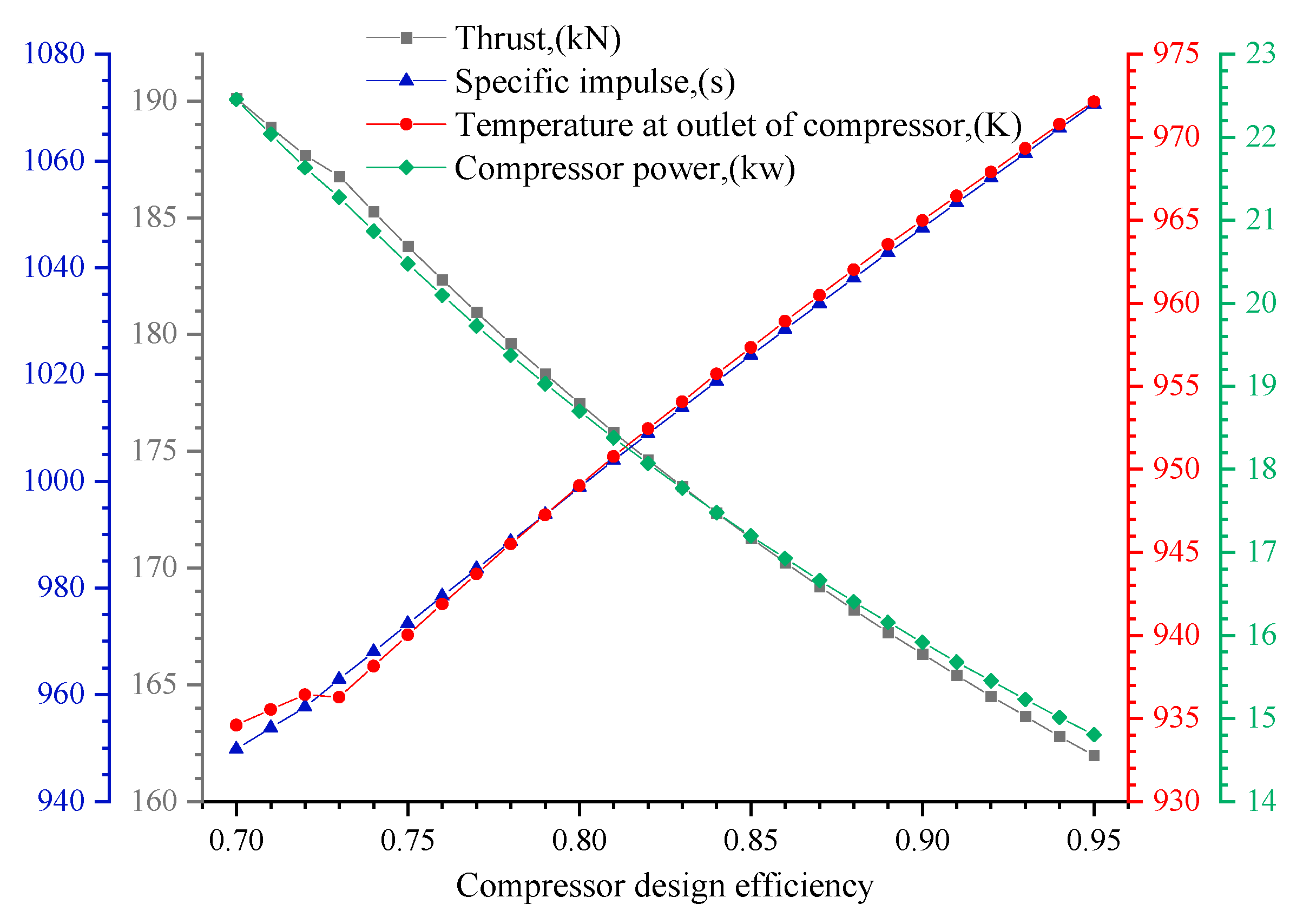
3.2.4. Selection of Compressor Design Efficiency

As shown in Figure 6, as the compressor design efficiency increased from 0.7 to 0.95, the thrust decreased almost linearly from 191 kN to 162 kN, while the specific impulse increased from 950 s to 1075 s in an approximately positive linear relationship with the compressor design efficiency.
As is shown in Figure 6, the air total temperature at the outlet of the pre-cooler and the total temperature at the outlet of the compressor had similar trends, both of which increased with the compressor design efficiency, and they fluctuated around 0.73.
According to Figure 6, the total temperature at the outlet of the compressor increased with the compressor design efficiency. The compressor power decreased when the compressor design efficiency increased. This will result in the flow decreasing accordingly, which also reduces the engine thrust. If the economy is considered, the compressor efficiency should be as high as possible, so as to make the specific impulse as large as possible. The temperature of air at the outlet of the compressor should be less than 950 K, so the design compressor efficiency is limited to 0.85.

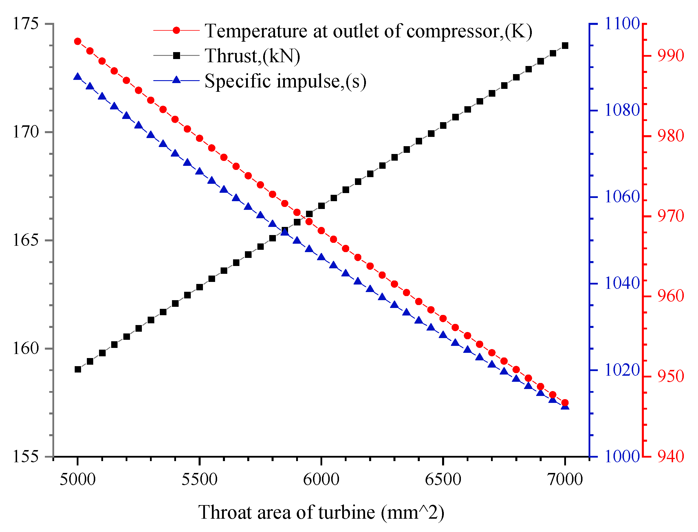
3.2.5. Selection of the Design Throat Area of Turbine

As is shown in Figure 7, the throat area of the turbine increased from 5000 mm2 to 7000 mm2, and the thrust increased with the increase in turbine throat area. Additionally, the specific impulse and turbine throat area were approximately negatively correlated.
The turbine throat area increased from 5000 mm2 to 7000 mm2, and the air total temperature at the outlet of the pre-cooler and the compressor decreased with the design pressure ratio. Considering the economy, if the specific impulse is expected to be higher, the turbine throat area is required to be smaller. However, due to material limitations, the total temperature at the compressor outlet should be less than 950 K. After comprehensive consideration, the turbine throat area was finally selected as 6600 mm2

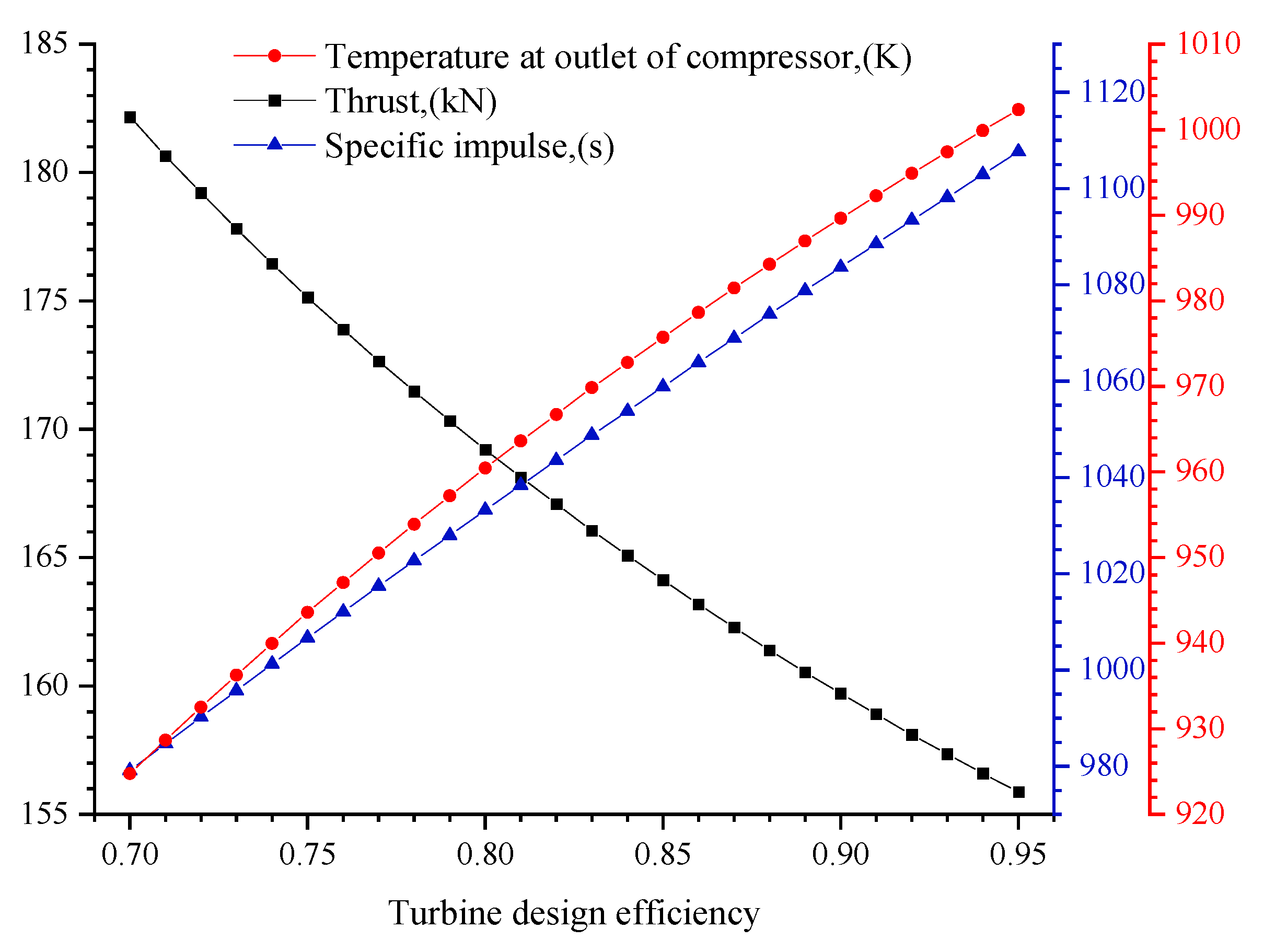
3.2.6. Selection of Turbine Design Efficiency

As is shown in Figure 8, the turbine efficiency increased from 0.7 to 0.95, and the thrust decreased almost linearly from 183 kN to 155 kN. The specific impulse changed almost linearly with turbine efficiency, increasing from 975 s to 1120 s.
According to Figure 8, the total temperature at the outlet of the compressor increased linearly with turbine efficiency. If the economy is considered, the turbine efficiency should be as high as possible, and the greater the specific impulse, the better. However, high temperature will put forward higher requirements for the heat resistance of materials and thermal load capacity of various engine components. Due to the limitation of materials and existing engine design and manufacturing level, turbine efficiency cannot be too high. After comprehensive consideration, the turbine efficiency was finally selected as 0.78 to ensure that the temperature of air at the outlet of the compressor is less than 950 K.

4. Research on the High-Performance Design of the Key Components

After determining the overall performance index of the NUAA-PTRE, specific requirements were put forward for each component of the engine. For the first time, the engine used endothermic hydrocarbon fuel to cool air and combined a turbine engine with a rocket engine, so the structural design of components faced new requirements. In addition, the pre-cooled air turbo rocket engine faced the challenges of a wide speed range, from Ma 0 to Ma 5, as well as a wide altitude range, from 0 to 25 km. The engine should not only be able to cool the high-temperature air in effectively under the Mach 5 design conditions to achieve high-performance work, but it should also be able to cope with complex intake conditions. At the same time, the physical properties of the endothermic hydrocarbon fuel will undergo more complex changes under the temperature changes in different inlet air conditions. The cracking of fuel at high temperatures will have an impact on the fuel composition and thermodynamic parameters, which puts forward new requirements for the pre-cooler, rocket generator, and other components.

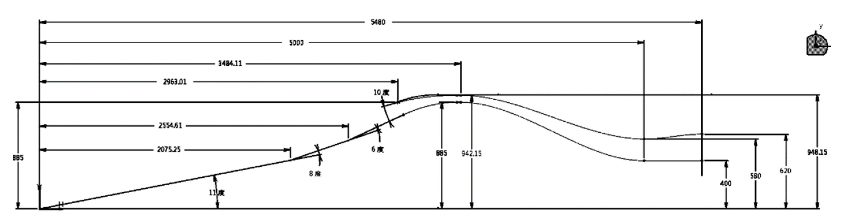
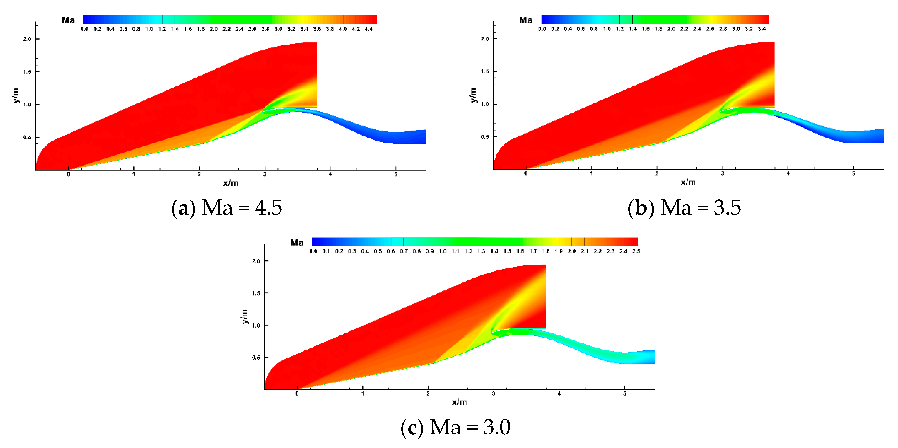
4.1. Ma 0~5 Wide-Range High-Performance Inlet Design

Due to the wide working range of the NUAA-PTRE, the inlet Mach number changes from 0 to 5. If a fixed structure inlet is used, a large amount of inlet loss will occur under off-design conditions. In order to improve the performance loss caused by deviation from the design point, it was necessary to carry out research on the inlet technology at a wide Mach number range to improve the performance parameters of the inlet at non-design points and to meet the performance requirements of the combined-cycle propulsion system for the inlet in the Ma 0~5 wide speed range. The design optimization of the Ma 0~5 wide-range, high-performance, adjustable inlet port was carried out according to the specific changes in the inlet conditions.
The capture area and capture radius of the inlet can be calculated according to the design flow required by the overall engine at the high-altitude point. On this basis, the two-dimensional axisymmetric scheme design and numerical simulation were carried out, and the inlet wave system was designed by changing the seal Mach number, the total turning angle of the external pressure section, the inlet internal pressure angle, and the inlet capture radius. The best wave system design scheme was selected through comparison to determine which scheme could meet the intake flow required by the engine under Ma 5 and to achieve shock wave fitting. The Mach number of the throat was between 2.0 and 2.5, and the total pressure recovery coefficient was higher, reaching 0.68, reducing the total inlet pressure loss. On the basis of determining the wave system design scheme, the diffuser was designed after its throat, and the design scheme with the strongest back pressure bearing capacity was selected. The total pressure recovery coefficient at the outlet was 0.3332, the Mach number at the outlet was 0.262, the maximum allowable back pressure was 420 Mpa, and the maximum static pressure ratio was 168.5. Finally, the structure and size design of the air intake was completed, with an axial length of 5480 mm and throat diameter of 948.15 mm, as shown in Figure 9.
In order to achieve high efficiency intake in the wide range of Ma 0~5, the variable geometry inlet was preliminarily explored. In order to ensure the normal operation of the inlet at an off-design Mach number, the key parameter was the throat area of the inlet. After several modifications, it was determined that the throat area of the inlet was adjustable in three stages: Ma 4~5, Ma 3~3.5, and Ma 2.5 and below. The geometric parameters of the three-stage inlet are shown in Table 2. As the intake Mach number increases, the throat area decreases, which requires larger outer diameter of throat or smaller inner diameter of throat. The outer diameter of throat is designed, being constant under different intake air conditions to reduce the diameter of the intake, so that the inner diameter of throat increases with increasing Mach number.
Figure 10 shows the Mach number contour map of the inlet flow field at and off-design Mach number. Each map shows the flow field map under the maximum back pressure state, and the back pressure needed to be adjusted continuously during calculation until the end shock wave was pushed to the throat (supersonic state) or the inlet flow reached the required value (subsonic state). When the Mach number was 5, the flow rate was 142.94 kg/s, meeting the flow requirements. When the Mach number was 0.262, the total pressure recovery coefficient σ was 0.3332, and the maximum back pressure can reach 168.5 times of inlet pressure. At Ma 4.5, the flow was 144.02 kg/s, which was less than the required flow. When the Mach number was 0.260, the total pressure recovery coefficient σ = 0.4325, and the maximum withstanding back pressure was 119.6 times greater. At Ma 4.0~2.0, the inlet flow was greater than the flow required by the technical requirements. At Ma 1.3~0, the inlet flow could be equal to the required flow by adjusting the inlet–outlet back pressure. As mentioned above, the intake flow was increased, and the intake pressure loss was reduced through the three-stage variable-structure intake port. The intake air flow at the design point of Ma 0 and 0 km above sea level was 142.94 kg/s, which meets the requirements of the NUAA-PTRE for the intake air duct under the condition of wide-range Ma 0~5 intake air.

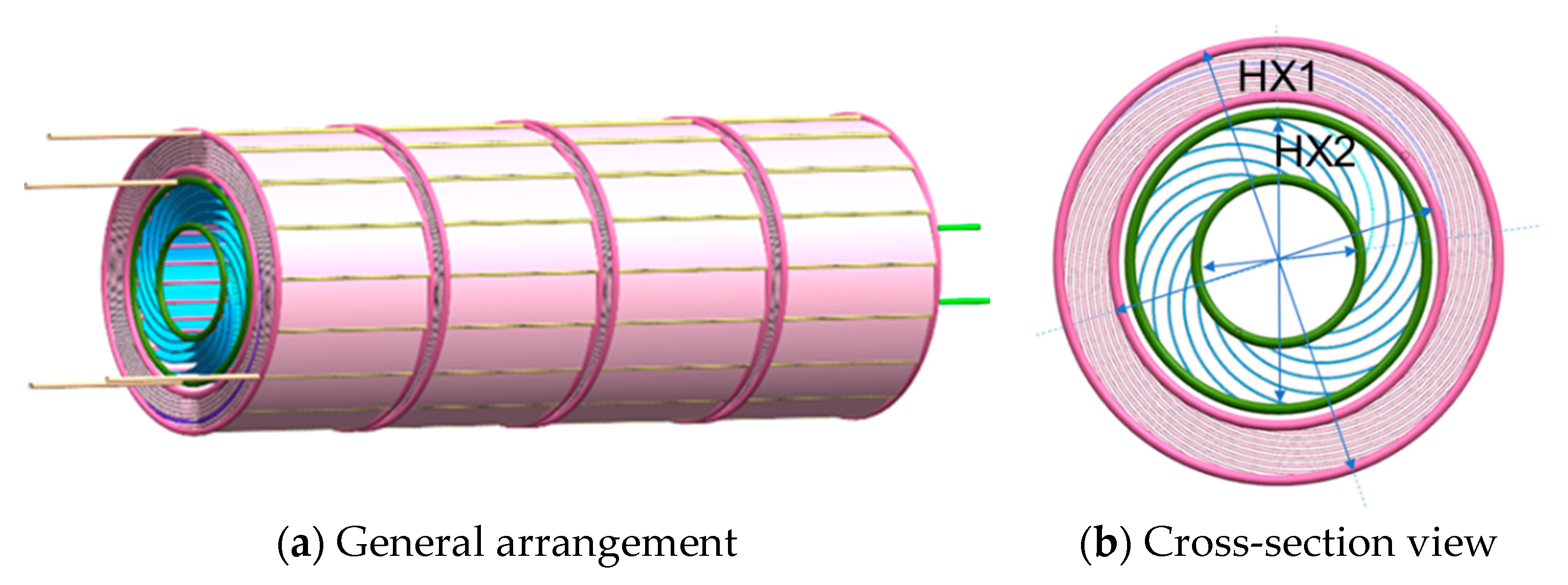
4.2. Design of High Heat Load and the Compact Tandem Pre-Cooler

During the flight at a high Mach number of Ma 4~5, in order to prevent the intake stagnation temperature from exceeding the heat resistance limit of the compressor and turbine materials due to excessive intake stagnation temperature, and to maintain the performance of the power system, it was necessary to reduce the intake temperature and increase the compressor pressure ratio in the intake system through the pre-cooler; this is of great significance for the hypersonic vehicle to expand the flight envelope of the vehicle and to improve the thrust weight ratio of the engine. To achieve the normal operation of the NUAA-PTRE at a high Mach number, it was necessary to increase the total heat transfer efficiency of the multi-stage pre-cooling device to more than 0.85; it was also necessary to increase the work weight ratio of the heat exchanger to more than 62 kW/kg to meet the requirements of structural compactness and weight, and the temperature in front of the turbine was required to be less than 1600 K to reduce the heat load of materials.
In order to achieve these targets, the NUAA-PTRE puts forward newer and higher technical and indicator requirements for the pre-cooler compared with the traditional aspirated pre-cooled combined engine. That is, under high-Mach-number flight conditions, two cooling media, oxidant and endothermic hydrocarbon fuel, were used to cool the air, step-by-step; in addition, the high heat sink during the pyrolysis of the endothermic hydrocarbon fuel was used to improve the pre-cooler’s pre-cooling capacity, as well as to cool the air from 1330 K to 810 K at a Ma 5 design point. The contradiction between flow resistance and heat transfer is the design difficulty of a compact pre-cooler with a light weight and high efficiency. At the same time, there are difficulties in the calculation of the physical parameters of the cooling medium from the liquid state to the supercritical state and the high-temperature cracking reaction. In view of the above key technical requirements, the research team, based on the accumulation of previous research achievements on the pre-cooler, designed the overall countercurrent layout, double-layer inner and outer ring nested structure, and highly compact pre-cooler structure, according to the requirements of the overall plan. With comprehensive consideration of the liquid heat transfer process, super critical heat transfer process, cracking endothermic reaction, and changes in the physical parameters of each section, the heat transfer characteristics of the pre-cooler were predicted accurately.
The pre-cooler was composed of internal and external annular pre-coolers in series, as shown in Figure 11. The outer ring is pre-cooler 1 (air/endothermic hydrocarbon fuel), and the inner ring is pre-cooler 2 (air/oxidant). The working process of the pre-cooler can be divided into two series stages: the cooling stage of the endothermic hydrocarbon fuel and the oxidant cooling stage, during which the hot air is successively cooled by the endothermic hydrocarbon fuel and oxidant in the pre-cooler. For the cooling stage of the endothermic hydrocarbon fuel, the fuel with a low temperature and high pressure flows into the main pipe of the inner ring of pre-cooler 1, then enters each branch pipe, distributes evenly to each pre-cooler, flows into the capillary bundle, gradually absorbs the heat of high-temperature air, and finally flows out through the branch pipe and main pipe of the outer ring. High temperature air washes each group of capillary tube bundles laterally along the radial direction, gradually releasing heat and being cooled. In the oxidant cooling stage, similar to the previous stage, the oxidant with low temperature and high pressure flows into the main pipe of the inner ring of pre-cooler 2, flows through the branch pipe and capillary tube bundle, and further cools the high-temperature air flowing from preheater 1 to reduce it to the expected temperature after pre-cooling.
Table 3 and Table 4 compare the numerical calculation results and design requirements of the pre-cooler. It can be seen from Table 3 that the total pressure loss of air at the design point (Ma = 5) was small, with a total pressure loss of 2% and a heat exchange efficiency of 0.828. Compared with the requirements of a 856 K pre-cooling outlet temperature and heat exchange efficiency, the pre-cooler structure needed to be further optimized. The total pressure loss was smaller than expected. The heat exchange capacity of pre-cooler 1 could be further improved by increasing the heat exchange area. It can be seen from Table 4 that the heat exchange efficiency of pre-cooler 2 was 0.99, the heat exchange capacity of pre-cooler 2 had met the design requirements, the outlet temperature of oxidant was close to the inlet air temperature, and pre-cooler 2’s pre-cooling capacity could be further improved only by increasing the oxidant flow rate of pre-cooler 2.
CFD simulation of flow and heat transfer was carried out for the pre-cooler. After the air passed through the two-stage pre-cooler, the temperature gradually decreased and was cooled, from 1300 K to 870 K, as shown in Figure 12. The preliminary designed pre-cooler had a work–weight ratio of more than 100 kW/kg and a compactness of 278 m2/m3, which was nearly twice the work–weight ratio of 65 kW/kg required for the overall plan, and this significantly improved the specific impulse of the engine. The total heat transfer efficiency of the two-stage pre-cooler exceeded 0.9, which meets the requirements of the NUAA-PTRE for efficient and compact heat transfer of the pre-cooler in the Ma 0~5-wide speed range. The feasibility of the pre-cooler scheme was preliminarily verified by numerical simulation, meeting the index requirements of the NUAA-PTRE overall plan.

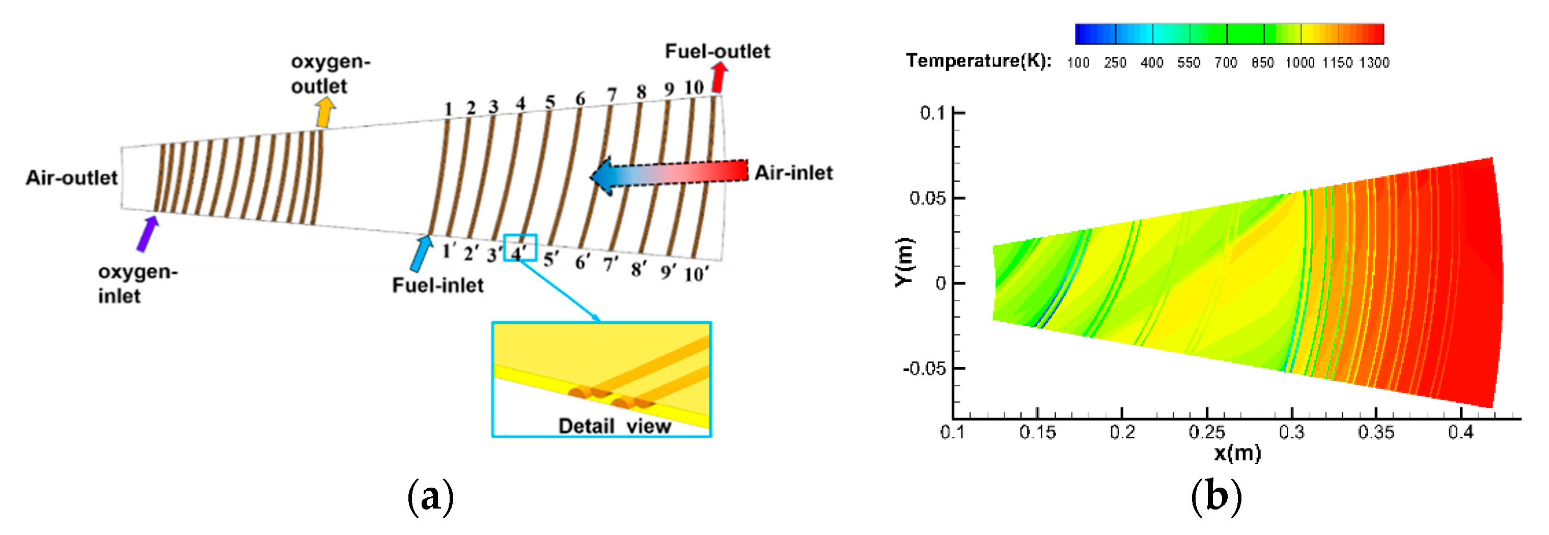
4.3. Design of a Wide-Flow-Range Built-In Rocket Generator

In the wide speed range of Ma 0–5, the endothermic hydrocarbon fuel at the outlet of the pre-cooler was characterized by a wide flow range and a wide temperature range. The fuel was in a macromolecular state before cracking and a small molecular state after cracking. With the rise in cracking temperature, the composition and concentration of the small molecular products became different. At the same time, the cracking of the endothermic hydrocarbon fuel under high temperature also presented the problem of coking, which may cause blockage of the injector, which brings great challenges to the design of the injector of the rocket generator. Under the wide airspace speed regime with a flight altitude of 0~25 km and flight speed of 0~5 Ma, the NUAA-PTRE required the flow variation range of oxidant to be 3.71~10.72 kg/s and the flow range of fuel to be 4.03~11.65 kg/s, achieving a 3:1 flow ratio.
In order to adapt to the structural characteristics of the NUAA-PTRE, the injector and combustion chamber of the rocket generator are mainly circular cylindrical structures. The nozzle layout adopts a 3 circle and 40 nozzle layout, with a total of 120 nozzles, as shown in Figure 13c. The flow requirements at the design point have been fulfilled. The total gas flow was 20.96 kg/s, the oxidant flow was 10.04 kg/s, and the gas fuel flow was 10.92 kg/s. The sectional structure of the rocket generator is shown in Figure 13a. The fuel and oxidizer enter the combustion chamber through the injector and ignite by electric spark ignition. The spark plug is located at the injector outlet. The oxidizer and gaseous fuel enter the combustion chamber from the nozzle outlet and ignite immediately.
The structure diagram of each injection unit is shown in Figure 13b. Coaxial DC nozzles were used for the gas fuel and oxidant. As the degree of fuel cracking at low temperatures was small and macromolecules accounted for a large proportion of the fuel components, the fuel was easy to coke in the pre-cooler to produce solid particles, which may lead to nozzle blockage. Therefore, the gaseous fuel was supplied from the central channel of the coaxial DC nozzle, and the oxidant was supplied from the outer annular channel. After a certain period of work, if the accumulated solid particles caused the fuel nozzle to become blocked, the central fuel nozzle could be replaced, and the outer epoxide nozzle could continue to be reused.
Under the design conditions, the combustion and heat transfer process of the rocket generator were simulated. There was a large density difference in the area near the injector, as shown in Figure 14a, which caused the gas fuel and oxidant to have a strong vortex effect at the end of the injector (or the head of the rocket generator), as shown in Figure 14b, indicating that the gas fuel and oxidant had been mixed violently in this area. The recirculation enhanced the mixing combustion, and a stagnation point with zero velocity was formed on the wall of the combustion chamber, resulting in a peak value of the heat flow there, forming a small high temperature zone.
Aimed at the working characteristics of Ma 0–5 with a wide 3:1 flow variation range and wide temperature range, the scheme demonstration, structural design, and three-dimensional flow field simulation of different injectors under built-in structural constraints were carried out, the coupled flow combustion characteristics were obtained, and the injection atomization scheme was optimized. Through the analysis of heat transfer and flow in the combustion chamber, the high temperature backflow area in the combustion chamber head was found, which provides an important reference for the structural optimization and thermal protection design of the combustion chamber. The heat load of the NUAA-PTRE at a high Mach number was reduced. The development of the built-in cylindrical rocket generator was adapted to the complex gas inlet formed by the cracking of the hydrocarbon fuel under different conditions, and the injector blockage caused by fuel coking was solved through the design of the detachable structure. This meets the requirements of the NUAA-PTRE for inlet air mixing and a wide-flow-rate change ratio in a rocket generator in a wide speed range of Ma 0~5 and at an altitude of 0~25 km, and it provides support for the realization of the NUAA-PTRE overall scheme.
This enables the NUAA-PTRE to work continuously in a wide speed domain and a wide space domain. Through the analysis of heat transfer and flow in the combustion chamber, the high temperature backflow area in the combustion chamber head was found, which provides an important reference for the structural optimization and thermal protection design of the combustion chamber. This ensures the high performance and stable operation of the NUAA-PTRE at a high Mach number.

5. Conclusions

The calculation model of the NUAA-PTRE was established, the overall thermal cycle process was analyzed, and the iterative calculation was completed. Through the optimization of design parameters and component level optimization, the engine performance was improved and working range of the engine was expanded.
(1)
According to the flight condition requirements, it was determined that the air flow rate was 142.730 kg/s and the temperature at the precombustion chamber was 1600 K under the working conditions at the design point where the Mach number was 5 and the altitude was 25 km. Taking the best comprehensive performance at the design point as the objective, the design pressure ratio of the compressor was determined to be 2.8; the design flow of the compressor was 120 kg/s; the design efficiency of the compressor was 0.85; the rear area of the turbine was 6600 mm2; and the turbine design efficiency was 0.78.
(2)
In order to realize the high-performance operation of the engine in a wide range, the engine components were optimized, so that the engine could work normally in the speed range of Ma 0~5 and altitude range of 0~25 km and maintain high performance and economy.
(3)
The optimization design technology of the adjustable inlet was studied. The throat area of the inlet was adjusted in three stages, adapting to the change in inlet conditions under Ma 0~5. Under Mach 5 design-point, the back pressure of the inlet can reach 420 Mpa, which is 168.5 times of the inlet pressure. The resistance capacity for backpressure blocks the effect of pressure from the gas generator and the combustion chamber. The cascade pre-cooling technology with a low resistance flow, high efficiency, and high power-to-weight ratio was studied. The design of a lightweight and efficient compact pre-cooler was preliminarily completed. The power-to-weight ratio of the pre-cooler exceeded 100 kW/kg, and the compactness reached 278 m2/m3. The technology of a built-in, wide-range, variable-flow rocket generator was studied. The annular cylindrical combustor and the bipropellant-mixed injector were designed. The coking problem of hydrocarbon fuel is solved through the detachable fuel nozzle at the central axis. The combustion and heat transfer processes of the rocket generator were simulated.

Author Contributions

Conceptualization, Z.Y., J.N. and F.J.; methodology, Z.Y. and Y.G.; software, Y.G. and T.Y.; validation, Z.Y., Y.G. and T.Y.; formal analysis, Z.Y., Y.G., Z.J., B.L., W.P.; investigation, B.G., X.W. and M.L.; resources, Z.Y. and J.N.; data curation, Z.Y.; writing—original draft preparation, Y.G. and T.Y.; writing—review and editing, Z.Y., B.L., Z.J., W.P., F.J.; visualization, Z.Y. and B.G.; supervision, Z.J. and F.J.; project administration, Z.Y.; funding acquisition, Z.Y. and J.N. All authors have read and agreed to the published version of the manuscript.

Funding

The authors would like to thank the financial support by the Science Center for Gas Turbine Project, entitled as “Research on the overall technology of Ma 0-5 pre-cooled turbo-rocket combied cycle engine”, under Grant Number P2021-A-I-001-002.

Conflicts of Interest

The authors declare no conflict of interest.

References

  1. Wang, W.W.; Dan, L.I.; Zeng, J. Development of Propulsion System for Near-Space HTHL High-Speed Vehicles Abroad. Gas Turbine Exp. Res. 2014, 27, 57–62. (In Chinese) [Google Scholar]
  2. Snyder, L.; Escher, D.; DeFrancesco, R.; Gutierrez, J.; Buckwalter, D. Turbine based combination cycle (TBCC)propulsion subsystem integration. In Proceedings of the 40th AIAA/ASME/SAE/ASEE Joint Propulsion Conference and Exhibit, Fort Lauderdale, FL, USA, 11–14 July 2004; p. 3649. [Google Scholar]
  3. Zhang, T.; Wang, Z.; Huang, W.; Chen, J.; Sun, M.-B. The overall layout of rocket-based combined-cycle engines: A review. J. Zhejiang Univ. -Sci. A 2019, 20, 163–183. [Google Scholar] [CrossRef]
  4. Dong, P.; Tang, H.; Chen, M. Study on multi-cycle coupling mechanism of hypersonic precooled combined cycle engine. Appl. Therm. Eng. 2018, 131, 497–506. [Google Scholar] [CrossRef]
  5. Dong, Z.; Sun, M.; Wang, Z.; Chen, J.; Cai, Z. Survey on key techniques of rocket-based combined-cycle engine in ejector mode. Acta Astronaut. 2019, 164, 51–68. [Google Scholar] [CrossRef]
  6. Kailasanath, K. Recent developments in the research on pulse detonation engines. AIAA J. 2003, 41, 145–159. [Google Scholar] [CrossRef]
  7. Pandey, K.M.; Debnath, P. Review on recent advances in pulse detonation engines. J. Combust. 2016, 2016, 4193034. [Google Scholar] [CrossRef]
  8. Heiser, W.H.; Pratt, D.T.; Daley, D.H. Hypersonic Airbreathing Propulsion; Aiaa: Reston, VA, USA, 1994. [Google Scholar]
  9. AIAA High Speed Air Breathing Propulsion Technical Committee. High speed air-breathing propulsion. Aerosp. Am. 2008, 46, 64–65. [Google Scholar]
  10. Auslender, A.H.; Suder, K.L.; Thomas, S.R. An Overview of the NASA FAP hypersonics project airbreathing propulsion research. In Proceedings of the 16th AIAA/DLR/DGLR International Space Planes and Hypersonic Systems and Technologies Conference, Bremen, Germany, 19–22 October 2009. AIAA-2009-7277. [Google Scholar]
  11. Jackson, T.A.; Eklund, D.R.; Fink, A.J. High speed propulsion: Performance advantage of advanced materials. J. Mater. Sci. 2004, 39, 5905–5913. [Google Scholar] [CrossRef]
  12. Varvill, R.; Bond, A. A comparison of propulsion concepts for SSTO reusable launchers. J. Br. Interplanet. Soc. 2003, 56, 108–117. [Google Scholar]
  13. Sato, T.; Tanatsugu, N.; Naruo, Y.; Omi, J.; Tomike, J.; Nishino, T. Development study on ATREX engine. Acta Astronaut. 2000, 47, 799–808. [Google Scholar] [CrossRef]
  14. Kobayashi, H.; Taguchi, H.; Kojima, T.; Sato, T. Performance analysis of Mach 5 hypersonic turbojet developed in JAXA. In Proceedings of the 18th AIAA/3AF International Space Planes and Hypersonic Systems and Technologies Conference, Tours, France, 24–28 September 2012; p. 5839. [Google Scholar]
  15. Varvill, R. Heat exchanger development at Reaction Engines Ltd. Acta Astronaut. 2010, 66, 1468–1474. [Google Scholar] [CrossRef]
  16. Hempsell, M. Progress on the SKYLON and SABRE. In Proceedings of the International Astronautical Congress, Beijing, China, 23–27 September 2013; Volume 11, pp. 8427–8440. [Google Scholar]
  17. Mehta, U.B.; Aftosmis, M.J.; Bowles, J.V.; Pandya, S.A. Skylon aerodynamics and SABRE plumes. In Proceedings of the 20th AIAA International Space Planes and Hypersonic Systems and Technologies Conference, Glasgow, Scotland, 6–9 July 2015; p. 3605. [Google Scholar]
  18. Jivraj, F.; Bond, A.; Varvill, R.; Paniagua, G. The scimitar precooled Mach 5 engine. In Proceedings of the European Conference for Aero-Space Sciences, Brussels, Belgium, 31 July 2007. [Google Scholar]
  19. GREINER Maj; Nathan, USAF. Advanced Full Range Engine (AFRE). Available online: https://www.darpa.mil/program/advanced-full-range-engine (accessed on 12 January 2018).
  20. Lu, Y.; Fei, H.; Yang, H.; Huang, Y.; Zhang, H. Effect of different cooling mediums on mass injection pre-compression cooling. Appl. Therm. Eng. 2022, 209, 118216. [Google Scholar] [CrossRef]
  21. Chen, Y.; Zou, Z.; Liu, H.; Li, H.; Li, H.; Zhao, R. Verification at Mach 4 heat conditions of an annular microtube-typed precooler for hypersonic precooled engines. Appl. Therm. Eng. 2022, 201, 117742. [Google Scholar] [CrossRef]
  22. Yu, X.; Wang, C.; Yu, D. Thermodynamic assessment on performance extremes of the fuel indirect precooled cycle for hypersonic airbreathing propulsion. Energy 2019, 186, 115772. [Google Scholar] [CrossRef]
  23. Hou, Z.Y.; He, G.Q.; Li, W.Q.; Qin, F.; Wei, X.G.; Jing, T.T. Numerical investigation on thermal behaviors of active-cooled strut in RBCC engine. Appl. Therm. Eng. 2017, 113, 822–830. [Google Scholar] [CrossRef]
  24. Ma, X.; Jiang, P.; Zhu, Y. Performance analysis and dynamic optimization of integrated cooling and power generation system based on supercritical CO2 cycle for turbine-based combined cycle engine. Appl. Therm. Eng. 2022, 215, 118867. [Google Scholar] [CrossRef]
  25. Zhao, W.; Huang, C.; Zhao, Q.; Ma, Y.; Xu, J. Performance analysis of a pre-cooled and fuel-rich pre-burned mixed-flow turbofan cycle for high speed vehicles. Energy 2018, 154, 96–109. [Google Scholar] [CrossRef]
  26. Fernández-Villace, V.; Paniagua, G.; Steelant, J. Installed performance evaluation of an air turbo-rocket expander engine. Aerosp. Sci. Technol. 2014, 35, 63–79. [Google Scholar] [CrossRef] [Green Version]
  27. Rodríguez-Miranda, I.; Fernández-Villacé, V.; Paniagua, G. Modeling, Analysis, and Optimization of theAir-Turborocket Expander Engine. J. Propuls. Power 2013, 29, 1266–1273. [Google Scholar] [CrossRef]
  28. Webber, H.; Bond, A.; Hempsell, M. Sensitivity of pre-cooled air-breathing engine performance to heat exchanger design parameters. In Proceedings of the 57th International Astronautical Congress, Valencia, Spain, 2–6 October 2006. [Google Scholar] [CrossRef]
  29. Zhang, J.; Wang, Z.; Li, Q. Thermodynamic efficiency analysis and cycle optimization of deeply precooled combined cycle engine in the air-breathing mode. Acta Astronaut. 2017, 138, 394–406. [Google Scholar] [CrossRef]
  30. Gu, R.; Sun, M.; Li, P.; Cai, Z.; Yao, Y. A novel experimental method to the internal thrust of rocket-based combined-cycle engine. Appl. Therm. Eng. 2021, 196, 117245. [Google Scholar] [CrossRef]
  31. Ji, Z.; Zhang, H.; Wang, B. Thermodynamic performance analysis of the rotating detonative airbreathing combined cycle engine. Aerosp. Sci. Technol. 2021, 113, 106694. [Google Scholar] [CrossRef]
  32. Zuo, F.Y.; Mölder, S. Hypersonic wavecatcher intakes and variable-geometry turbine based combined cycle engines. Prog. Aerosp. Sci. 2019, 106, 108–144. [Google Scholar] [CrossRef]
  33. Wei, X.; Jin, F.; Ji, H.; Jin, Y. Thermodynamic analysis of key parameters on the performance of air breathing pre-cooled engine. Appl. Therm. Eng. 2022, 201, 117733. [Google Scholar] [CrossRef]
  34. Sakamoto, Y.; Kobayashi, H.; Naruo, Y.; Takesaki, Y.; Nakajima, Y.; Kabayama, K.; Sato, T. Investigation of boiling hydrogen flow characteristics under low-pressure conditions-Flow regime transition characteristics. Int. J. Hydrog. Energy 2021, 46, 8239–8252. [Google Scholar] [CrossRef]
  35. Huang, C. Research on air turbo ramjet expander engine component matching and performance optimization. Ph.D. Thesis, Institute of Engineering Thermophysics, Chinese Academy of Sciences, Beijing, China, 16 December 2018. (In Chinese). [Google Scholar]
  36. Zhang, M.; Nan, X.; Liu, D. Principles and realizing ways of combined power system for pre-cooling air turbo rocket. J. Rocket. Propuls. 2016, 42, 6–12. (In Chinese) [Google Scholar]
Figure 1. The structure of the NUAA-PTRE.
Aerospace 10 00185 g001
Figure 2. Thermal cycle diagram of the air circuit.
Aerospace 10 00185 g002
Figure 3. (a) Data comparison between the NUAA-PTRE and PATR engine. (b) Thrust variation of NUAA-PTRE.
Aerospace 10 00185 g003
Figure 4. Variations in thrust, specific impulse, and the temperature at the outlet of the compressor, with compressor design pressure ratio.
Aerospace 10 00185 g004
Figure 5. Variations in thrust, specific impulse, and temperature at the outlet of the compressor, with compressor design air flow considered.
Aerospace 10 00185 g005
Figure 6. Variations in thrust, specific impulse, the temperature at the outlet of compressor, and compressor power with compressor design efficiency.
Aerospace 10 00185 g006
Figure 7. Variations of thrust, specific impulse, and temperature at the outlet of compressor with throat area of turbine.
Aerospace 10 00185 g007
Figure 8. Variations in thrust, specific impulse, and temperature at the outlet of compressor with turbine design efficiency.
Aerospace 10 00185 g008
Figure 9. Structure of the intake.
Aerospace 10 00185 g009
Figure 10. Mach number contour map of the inlet flow field.
Aerospace 10 00185 g010
Figure 11. The structure of the pre-cooler.
Aerospace 10 00185 g011
Figure 12. Symmetrical plane (a) calculation model and (b) temperature distribution of the pre-cooler.
Aerospace 10 00185 g012
Figure 13. Schematic diagram of injector structure.
Aerospace 10 00185 g013
Figure 14. (a) Density distribution and (b) temperature distribution in the gas generator.
Aerospace 10 00185 g014
Table 1. The typical trajectory of the PATR engine.
Mach number0.01.02.03.04.05.0
Altitude/km0.03.3211.4817.3421.7325.0
Table 2. Geometric parameters of the intake.
Mach NumberMa 4~5Ma 3~3.5Ma 0~2.5
Outer diameter
of throat (mm)
1884.31884.31884.3
Inner diameter
of throat (mm)
1770.01731.91693.8
Throat area (m2)0.328 0.4330.535
Table 3. Comparison between the simulation and design requirements of pre-cooler 1.
Temperature after Pre-CoolingTotal Pressure Recovery Coefficient of AirOutlet Temperature of EHFTotal Pressure Recovery Coefficient of EHFHeat Exchange PowerHeat Exchange Efficiency
Simulation934 K0.021151 K0.00265 MW0.828
Design requirement856 K<=0.081257 K<=0.0977.5 MW>=0.93
Table 4. Comparison between the simulation and design requirements of pre-cooler 2.
Temperature after Pre-CoolingTotal Pressure Recovery Coefficient of AirOutlet Temperature of OxidantTotal Pressure Recovery Coefficient of OxidantHeat Exchange PowerHeat Exchange Efficiency
Simulation870 K0.005926 K0.00310.37 MW0.99
Design requirement809.3 K<=0.08820.6 K<=0.099.08 MW>=0.94
Disclaimer/Publisher’s Note: The statements, opinions and data contained in all publications are solely those of the individual author(s) and contributor(s) and not of MDPI and/or the editor(s). MDPI and/or the editor(s) disclaim responsibility for any injury to people or property resulting from any ideas, methods, instructions or products referred to in the content.

