1. Introduction
Aircraft systems operate in a very challenging thermal environment. While outside temperatures can be between −70 °C to +55 °C, unpressurized equipment bays may have even higher temperature ranges. Traditionally, most electronic equipment (also called avionics boxes) is installed in pressurized or ventilated zones. In commercial and business aircraft, these equipment bays are typically ventilated through the aircraft environmental control systems (ECS). Equipment bays generally are tightly packed to minimize the space required, leaving usable space for passengers or other payloads. In addition, the ventilation should ideally be kept to a minimum, not penalizing the ECS and thus the overall aircraft weight, drag and power consumption.
The thermal analysis of equipment bays is typically challenging, as it requires detailed information about the geometry, system operation and heat loads, and the potential ventilation system supply. Hence, aircraft thermal analyses are carried out later in the design stage when bay architecture is well defined. Therefore, any thermal issues discovered late in the development of a new aircraft may lead to major costly modifications and delays in the development cycle. The thermal analysis of aircraft equipment bays is typically performed to validate if the design meets the minimal certification requirements rather than optimizing the cooling strategy or the system placement upfront in the conceptual design. A non-optimal aircraft design is against the aim of reducing the environmental footprint of future aircraft.
The importance of thermal considerations, particularly for future aircraft, has been recently exposed in a review paper by Van Heerden et al. [
1]. The current literature on thermal analysis in aircraft focuses mainly on passenger cabin studies [
2,
3]. Butler et al. [
4,
5,
6] published work for the aircraft crown area. With the advent of more electrical actuator technologies, several researchers focused on this particular aspect [
7,
8,
9]. Also, recent literature discusses details about battery thermal management for hybrid or all-electric aircraft [
10]. Sanchez et al. [
11] formulated the need for a multi-level approach to improving thermal analysis throughout the development process of future aircraft to meet the need to introduce thermal analysis earlier in the development cycle. In particular, the authors developed a so-called thermal risk assessment (TRA) methodology suitable for conceptual design [
12,
13].
The prior work shows a knowledge gap for the thermal interactions occurring in typical tightly packed aircraft equipment bays. In particular, system thermal interactions, such as radiation, may play a more significant role in tightly packaged avionics bays [
13,
14]. In addition, mixed convection regime exists when the equipment bay’s ventilation flow rate is not strong enough to compete against buoyancy effects. The effect of radiation on mixed convection cooling of a ventilated cavity with multiple openings has been studied by Ezzaraa et al. [
15]. One of the study’s findings is that increasing radiation leads to a hotter environment in the cavity in the case of a mixed convection regime, while in the forced convection regime, increasing radiation has a positive effect on the cooling process.
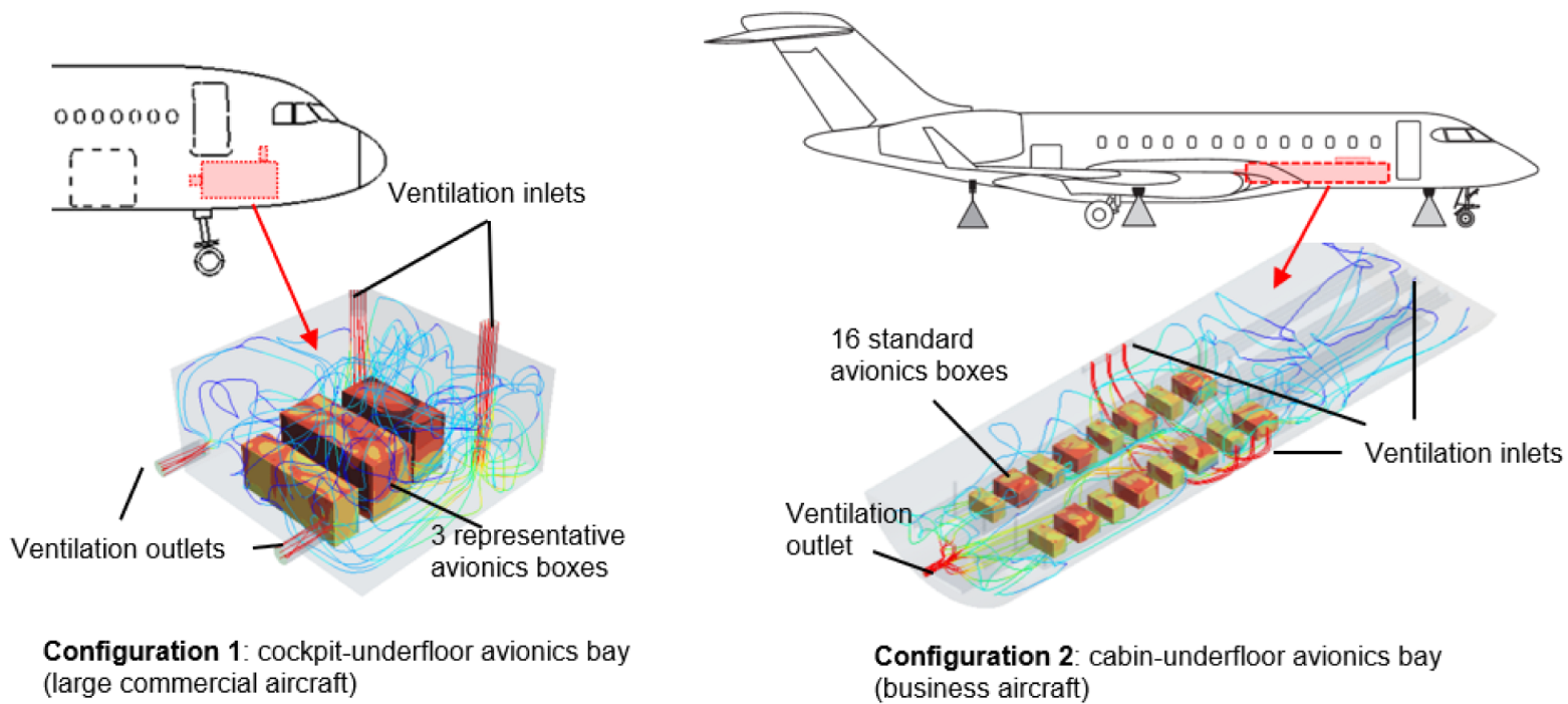
Therefore, this paper aims to study the effects of radiation on more complex geometrical configurations such as aircraft equipment bays. The authors investigate the influence of radiation on the overall system heat dissipation in two representative avionics bays, depicted in
Figure 1, using computational fluid dynamics (CFD). The aim is to gain knowledge about the conditions, which requires considering radiation in a conceptual design context, such as the TRA mentioned above.
Section 2 presents the assumptions, analyses and results for Configuration 1 and 2. The influence of gap width and ventilation flow rate is investigated using a parametric study. In addition, an analytical method is used to analyze the thermal interactions better.
Section 3 summarizes the findings and recommends the following steps to improve current conceptual design methods.
2. CFD Studies to Investigate the Influence of Heat Radiation on Aircraft Thermal Behavior
This CFD study investigates whether the influence of heat radiation inside an equipment bay is significant. The analyses carried out deal with two avionics equipment bay configurations:
A cockpit underfloor equipment bay, representative of a commercial narrow-body aircraft, such as the Airbus A320 (
Figure 1, Configuration 1).
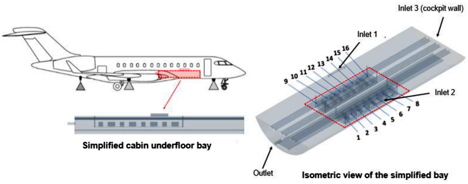
A cabin underfloor equipment bay, representative of a business aircraft, such as the Bombardier Global 5000 (
Figure 1, Configuration 2).
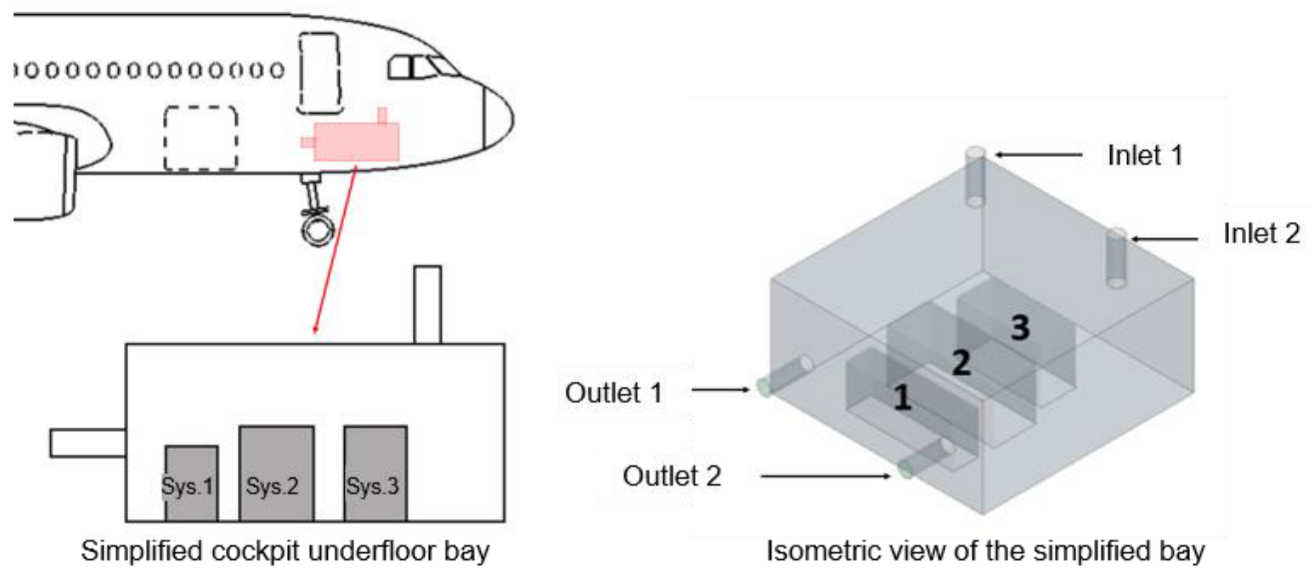
2.1. Description of the Cockpit-Underfloor Avionics Bay (Configuration 1)
This first configuration deals with the cockpit underfloor equipment bay of a commercial aircraft. The CFD study highlights the influence of heat radiative exchange on avionics equipment by comparing the cockpit underfloor thermal environment with and without radiation.
This type of avionics ventilation system is typically fully automatic and controlled by an avionics equipment ventilation computer. The ventilation air enters the bay from the cockpit through cockpit panels that use two exhaust fans. This air is then passed to the space under the cargo compartment with the help of an outlet bypass valve.
The approximate dimensions of the equipment bays are derived from the drawing of the aircraft available on the Airbus website [
16]. Notice that the geometry of this equipment bay has been simplified and is depicted in
Figure 2.
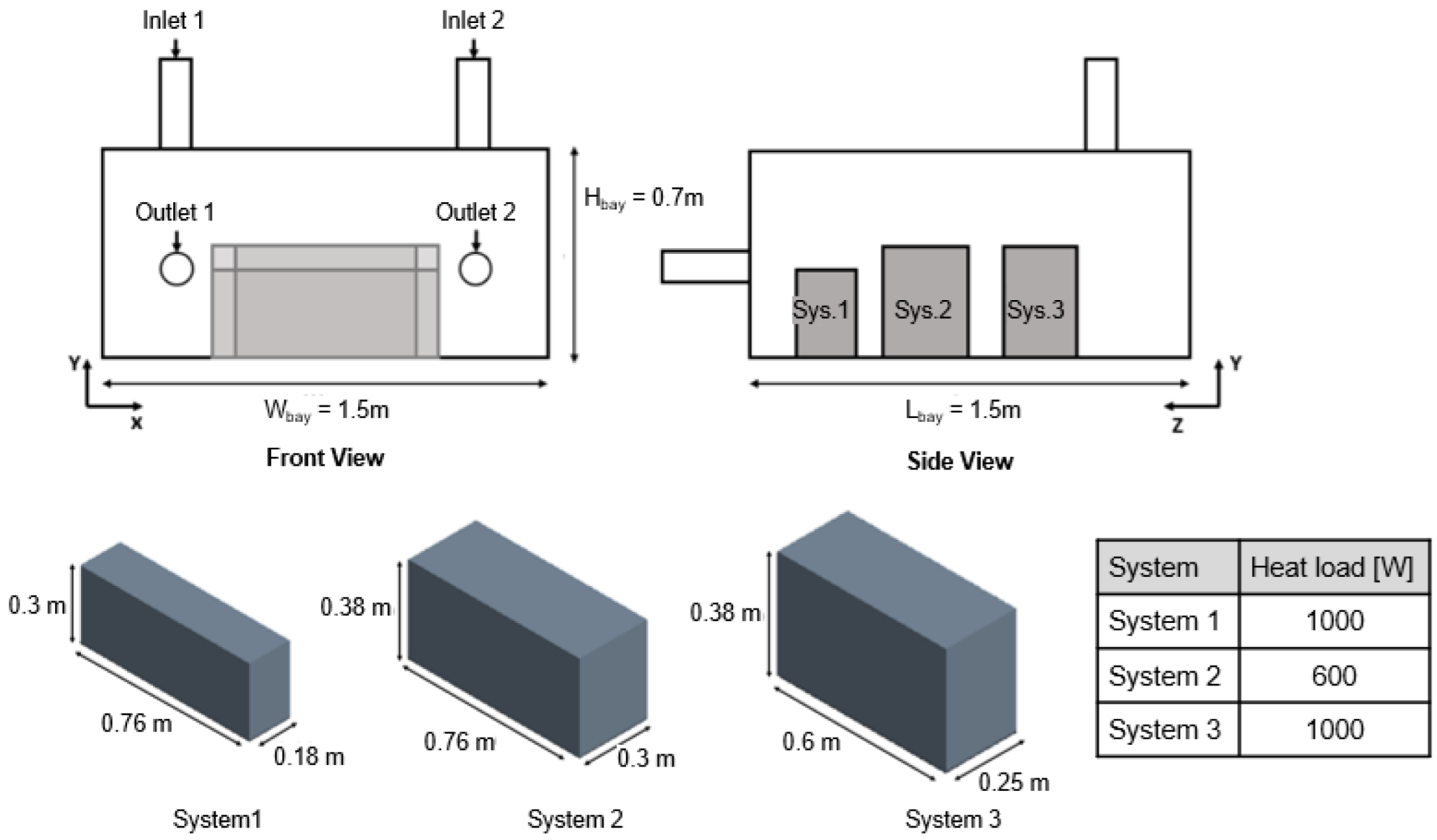
This study considers three systems similar to those used in previous work [
12,
13]. The first system is analogous to a High Voltage Power Supply (HVPS) with a heat load of 1000 W. Whereas System 2 and System 3 are assumed to be systems of the type “5 MCU” (Modular Concept Units) and type “3 MCU” with heat loads of 600 W and 1000 W, respectively.
Figure 3 summarizes the system specifications.
This configuration considers a hot day scenario with a ground-level ambient temperature of 55 °C (at 1 atm), which typically represents one of the most critical scenarios for aircraft thermal analysis. Due to the cockpit pressurization and controlled temperature, the top wall of the equipment bay, which is the cockpit floor, is assumed to be at 30 °C, whereas the underfloor equipment bay bottom wall is hotter at 55 °C. This configuration creates an unstable temperature gradient that requires modeling the buoyancy effects. All the other walls of the equipment bay are at 55 °C except the equipment bay left wall, which is assumed adiabatic. This wall represents the interface between the cockpit underfloor and the cabin underfloor equipment bay; its temperature depends on the thermal environment of the cabin underfloor bay, which is not considered in this study. According to the DO-160 standard [
17,
18,
19,
20], the systems have a temperature limit of 70 °C, which requires a mass flow rate of 0.035 kg/s-kW. Hence, to meet these standards, the total cooling mass flow rate is assumed at 0.0382 kg/s. The temperature of the inlet cooling air is assumed at 30 °C, and the outlet split ratio is 0.5, which means that outlets 1 and 2 extract the same mass flow. The boundary conditions are summarized in
Table 1.
The CFD model has the following characteristics:
Ideal and incompressible gas model.
Segregated flow and energy solvers with second-order convection schemes that use steady-state Reynolds Average Navier-Stoker equations (RANS) were selected because segregated solvers offered better convergence and numerical stability.
To model the turbulence effects of the flow, the authors selected the k-ω SST turbulent model with all y+ wall treatment based on benchmark studies conducted by Yuce and Pulat [
21].
Buyoancy is modeled using the Boussinesq approximation [
22].
Radiation is modeled using the S2S model of Star-CCM+, which is based on enclosure theory [
23,
24] and uses view factors to compute the radiative heat exchange.
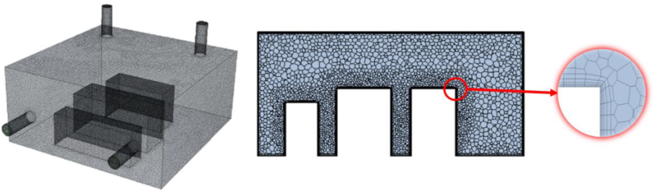
A mix of polyhedral and boundary layer meshes of 600 000 elements in total based on a grid independency study [
25] (
Figure 4).
2.2. Description of the Underfloor Equipment Bay (Configuration 2)
This second configuration deals with the cabin underfloor equipment bay, similar to the Bombardier Global 5000 (
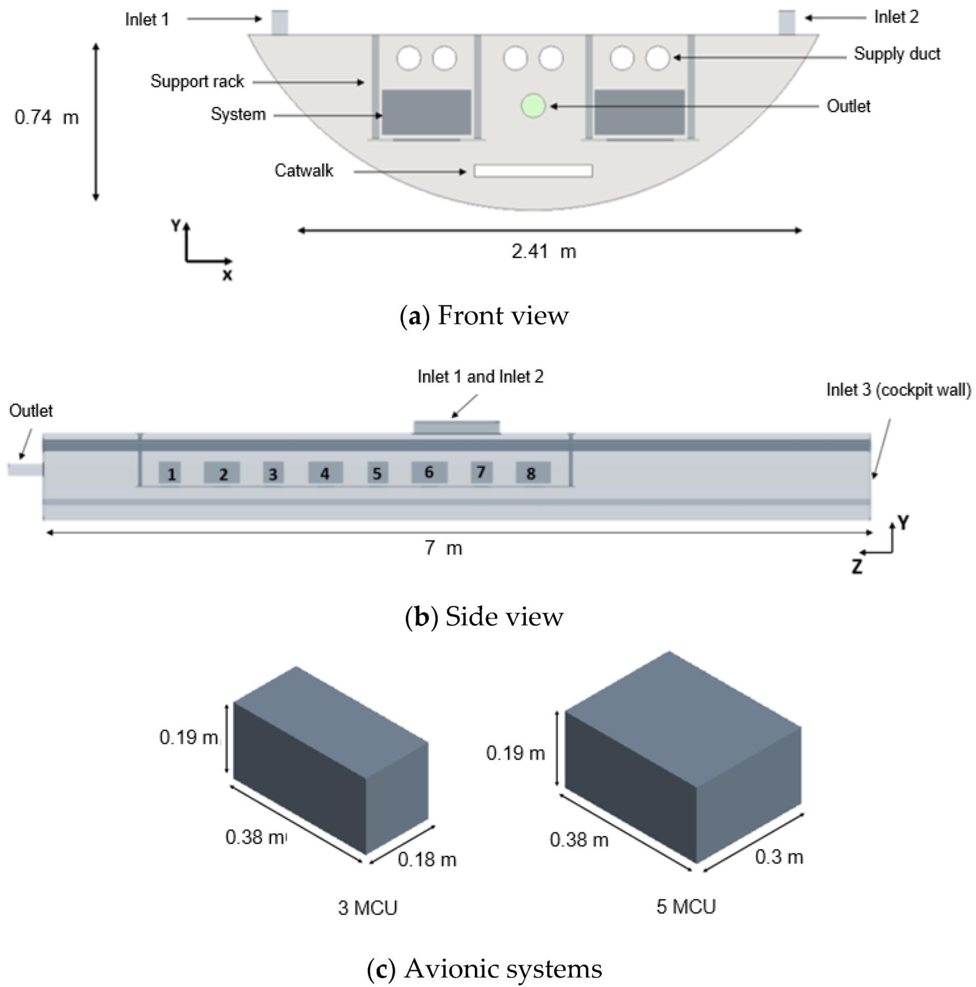
Figure 5). This configuration consists of two rows of eight systems located in a pressurized environment connected to the cockpit underfloor, the passenger cabin, and the belly fairing. In this CFD study, the authors investigate the effects of system distance gaps and ventilation flow rate on the system radiation magnitude.
In such an aircraft configuration, typically, the environmental control system (ECS) ventilates the air to the cabin underfloor equipment bay. The avionics exhaust system ensures the ventilation of the bay. The air enters the bay from the forward cabin exhaust. This air is then sucked through twin ducts via an avionics exhaust fan to the forward outflow valve [
18]. To generalize the bay configuration, the authors replaced the exhaust ducts by a single-outlet exhaust fan. It is assumed that flow also enters the equipment bay via cockpit exhaust in addition to the passenger cabin exhaust. The total airflow provided to the equipment bay represents 50% of the ventilation flow extracted from the passenger cabin. The remaining 50% of the ventilation is recirculated to the passenger cabin.
The bay sizes are derived from a sketch available in the pilot training guide of the aircraft [
19].
Figure 6 shows the generalized bay configuration.
This equipment bay consists of 16 systems, which are of the types 3 MCU and 5 MCU, according to avionics packaging standards, as depicted in
Figure 6c. They dissipate 300 W, and 500 W heat loads, respectively, for this case study, similar to the assumptions made in [
13]. The heat load dissipated by each avionic system is applied as a uniform heat source. The 3 MCU and 5 MCU systems are placed alternatingly, as shown in
Figure 6b.
As per MIL-STD-1472G standard [
20], for ease of maintenance, the minimum gap between avionics systems in equipment bays must be more than 0.045 m. The CFD study considers three different gap widths to evaluate the influence of the system gap on their radiative heat exchange. The smallest gap is 0.05 m, the minimum distance to satisfy certification constraints. The two other gap widths are 0. 1 m and 0.2 m, representing more considerable distances between the equipment when connection and wires require more space between the systems. The CFD study also considers three different ventilation flow rates representing different operating conditions of the ECS. The flow repartition is then derived from the ECS supply flow and assumed to be 22% for the cockpit and 78% for the passenger cabin.
Table 2 shows the parametric study conducted for the cabin underfloor equipment bay.
This study considers the ambient air temperature of 55 °C (at 1 atm). The top wall is at 30 °C, and the other bay walls are at 55 °C. Other objects inside the bay, such as the catwalk and the supporting rack, are assumed adiabatic to make this study as generic as possible. This equipment bay configuration has three inlets and one outlet, and the cooling air temperature is 30 °C.
Table 3 summarizes the boundary conditions.
The CFD model has the following characteristics:
Ideal and incompressible gas model.
Segregated flow and energy solvers with second-order convection schemes that use steady-state Reynolds Average Navier-Stoker equations (RANS) were selected because segregated solvers offered better convergence and numerical stability.
To model the turbulence effects of the flow, the authors selected the k-ω SST turbulent model with all y+ wall treatment based on benchmark studies conducted by Yuce and Pulat [
21].
Buoyancy is modeled using the Boussinesq approximation [
22].
Radiation is modeled using the S2S model of Star-CCM+, which is based on enclosure theory [
23,
24] and uses view factors to compute the radiative heat exchange.
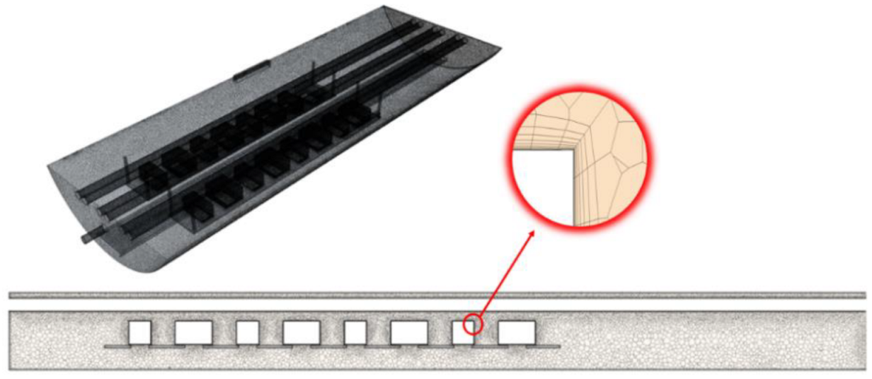
A mix of polyhedral and prism layer meshes of 3 800 000 elements in total based on a grid independency study [
25] (
Figure 7).
3. Results and Discussions
3.1. Effects of Radiation Heat Transfer on System Thermal Environment
Configuration 1 has been used to highlight the effects of radiation heat transfer on the overall system thermal environment.
Table 4 shows the results obtained for the surface averaged temperatures of the systems with and without radiation. It also gives the fraction of radiation in the total system heat flux.
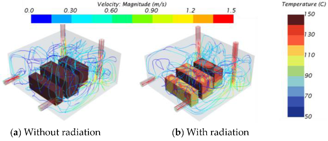
Figure 8 shows the CFD results obtained with and without considering radiation.
The results show that the radiative heat transfer brings down the temperature of the systems by 50% to 60%. Indeed, radiative heat exchanges with the adjacent systems and the bay walls allow the considered systems to exchange additional thermal energy. Moreover, the contribution of radiation represents 50% of the total heat flux dissipated by the systems.
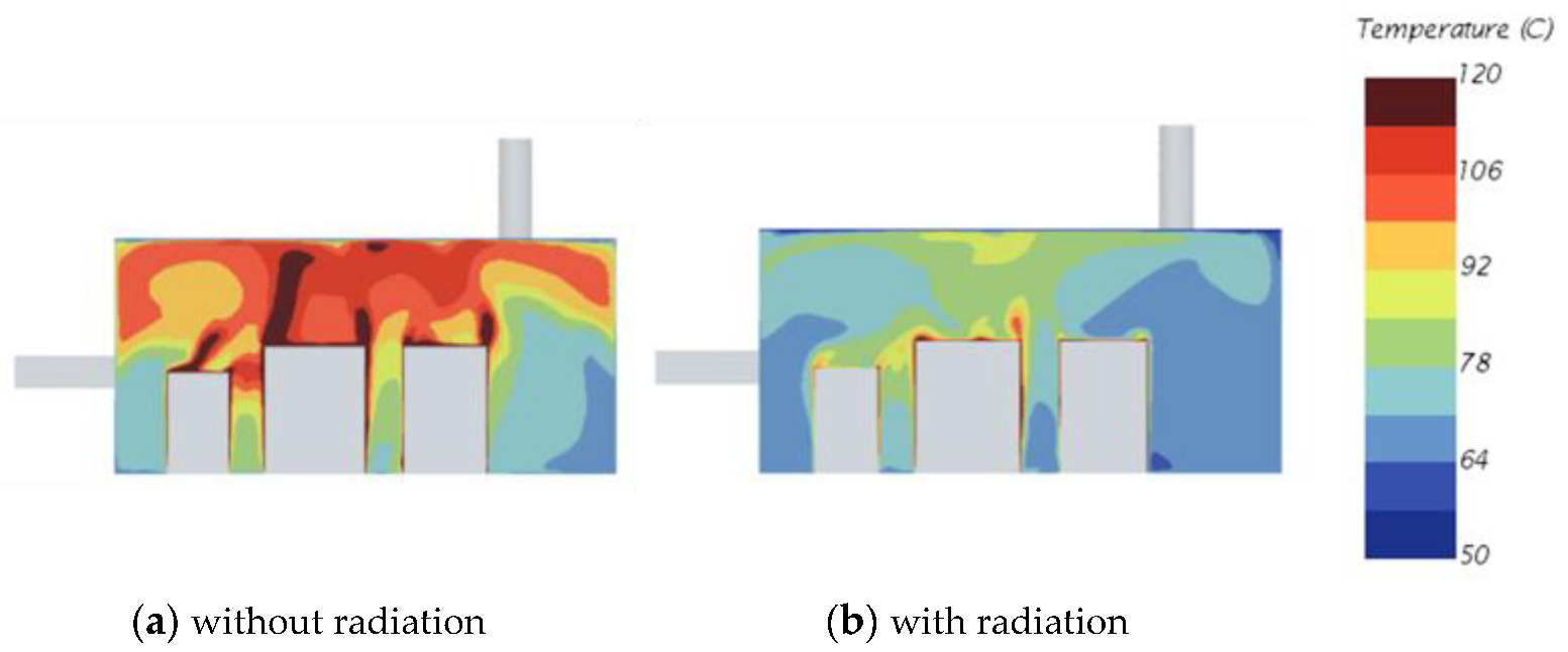
Figure 9 shows the air temperature surrounding the systems without and with radiation considered in the CFD simulation. When neglecting radiation, the boundary layer temperatures of the systems are hotter than when considering radiation. This means the systems dissipate more heat to their surrounding air when no radiation happens. In other words, radiation heat flux weakens the boundary layer.
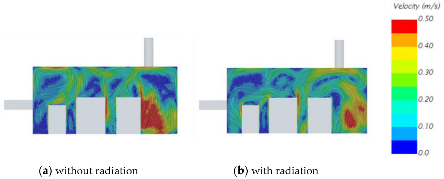
Figure 10 shows that radiation inside an equipment bay also impacts the velocity field. Because the systems dissipate more heat in their surrounding air, the plume effects are more substantial without radiation.
Overall, this study reveals that radiation significantly impacts equipment surface temperature and the overall thermal environment of an equipment bay. Radiation consideration cannot always be neglected when studying the thermal management of aircraft equipment bays.
3.2. Effects of Gap Distance between Adjacent Systems and Ventilation Flow Rate on Radiation Magnitude
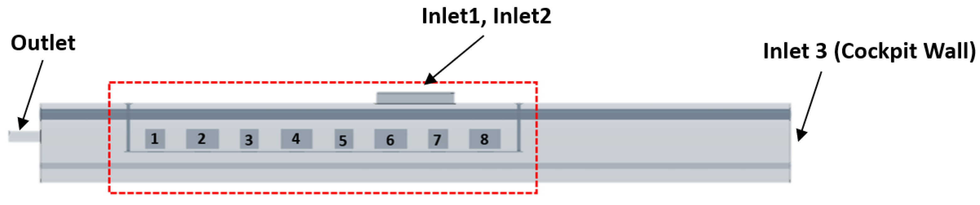
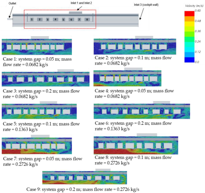
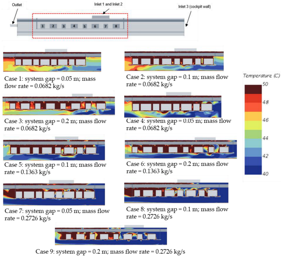
The underfloor equipment bay studied in configuration 2 allows the investigation of the impact of the gap distance between adjacent systems and the ventilation flow rate on the radiation magnitude. As the geometry of the underfloor equipment bay is symmetric, the following discussions will focus only on one side of the bay, which contains systems 1 to 8, and the temperature and velocity contour results will be only shown for the area defined by the red rectangular box in
Figure 11.
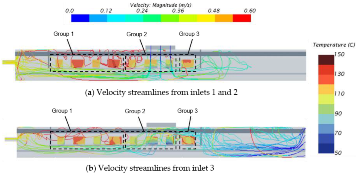
Figure 12 shows the CFD results for the velocity streamlines generated from the inlets. The mainstream inlet flows influence the systems thermal behavior close to the inlets. This allows organizing the systems into three groups according to their relative location with the inlets and outlets of the equipment bay.
Group 1 contains systems 1, 2, 3 and 4, located between the outlet and inlets 1 and 2 (cabin exhaust). Group 2 includes systems 5, 6 and 7 in front of inlets 1 and 2. Finally, Group 3 contains system 8 facing inlet 3 (cockpit exhaust).
To assess the proportion of radiation in the overall system heat transfer, the radiative and the total system heat fluxes are derived from the CFD results and used to calculate the radiative heat flux ratio.
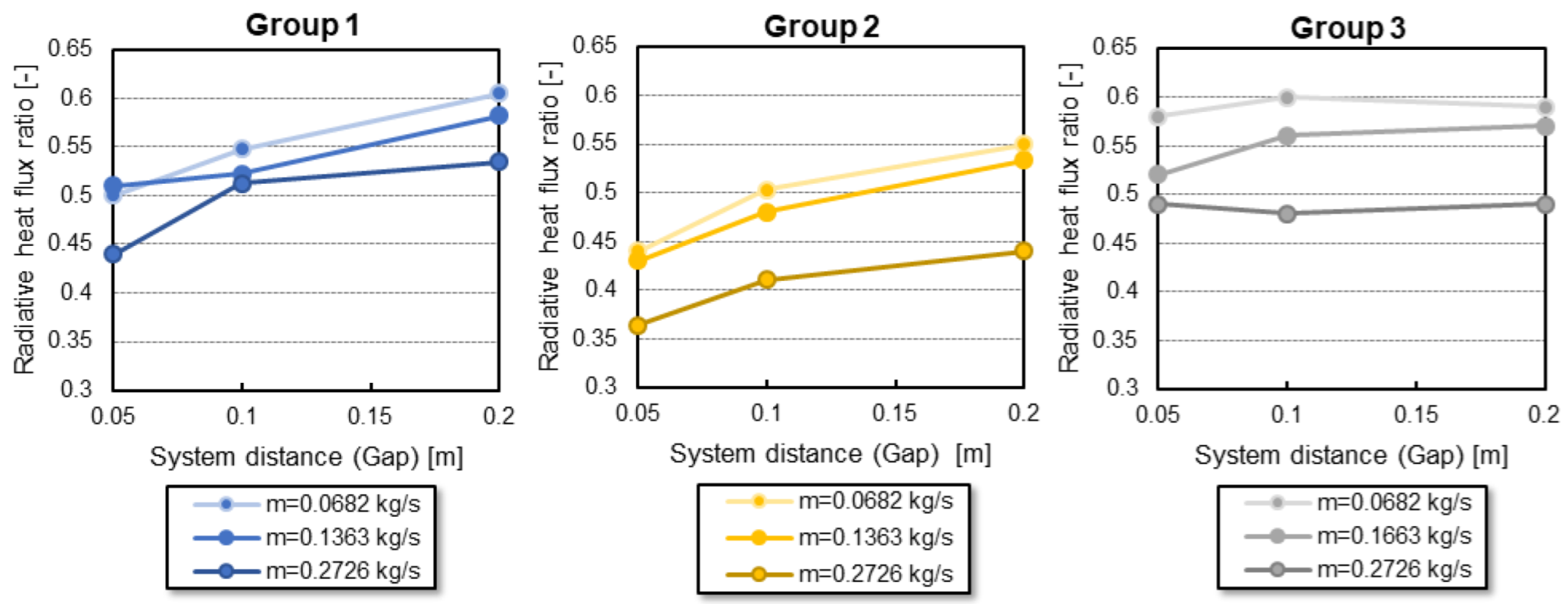
Figure 13 shows the evolution of this ratio averaged per group with the system distance.
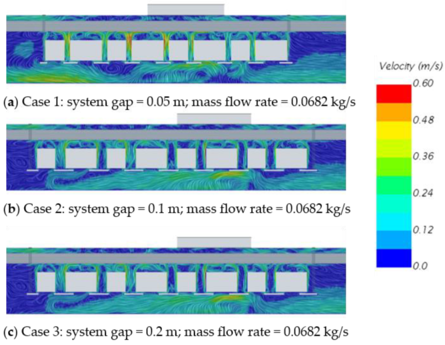
For groups 1 and 2, the radiative heat flux ratio increases with the gap distance between the systems for all the mass flow rate values.
Figure 14 shows the velocity contour for cases 1, 2, and 3 for the three studied gap distances with the smallest flow rate value. Here the CFD results show that the velocity magnitude in the gap area between the systems increases with the gap width. This also means that a small gap between the systems leads to higher velocity magnitude and, therefore, stronger convective than radiative heat exchange.
For group 3, the radiative heat flux ratio stays almost constant with the gap width variation between the system. The radiative heat flux ratio is less sensitive to the gap width than the other groups. Since only one system is in the group, its interaction with the other system is less critical as it has only one side facing another system. Indeed, the flow coming from the cockpit exhaust reaches the system in the same way, independent of the gap distance. Thus, the convective heat exchange is always of the same order of magnitude, which explains why the radiative heat exchange stays almost constant.
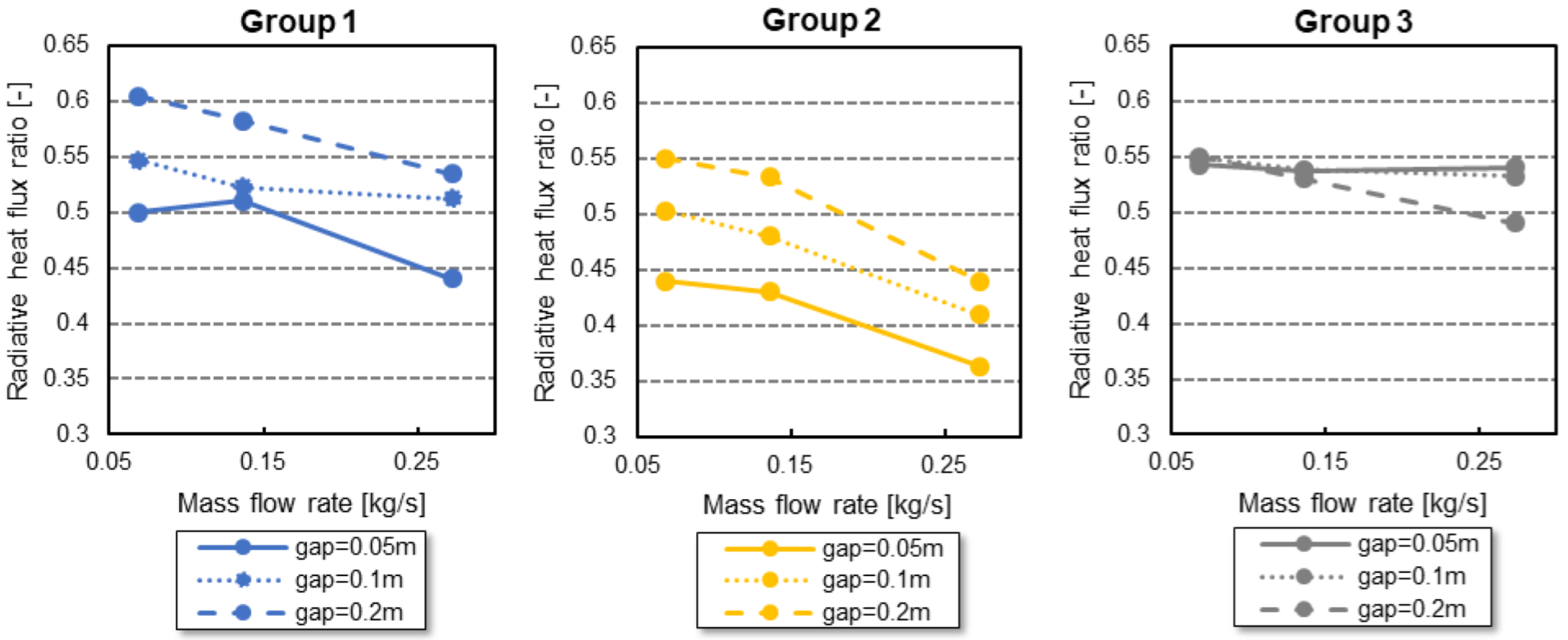
Figure 15 shows the radiative heat flux ratio as a function of the inlet mass flow for the three groups of systems.
For groups 1 and 2, the radiative heat flux ratio decreases with the mass flow rate for the three different system distances. Increasing mass flow rate leads to increased convective heat exchange between the systems and their environment; this increased convective heat exchange becomes more important than radiation.
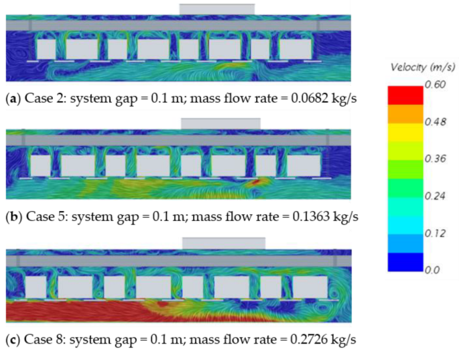
Figure 16 shows the velocity contours for cases 2, 5, and 8, which have the same system distance but different mass flow rates. The velocity magnitude in the gap between the systems increases with the distance, which confirms that convective effects gain in intensity with the distance between the systems.
For group 3, the radiative heat flux ratio stays constant while the mass flow rate increases, except for the lowest value of the inlet flow rate (
Figure 15). The combination of low flow speed and large system gap (
Figure 14c, Case 3) allows more air to fill the gap between systems 7 and 8, consequently increasing the convective effects at the cost of the radiative ones.
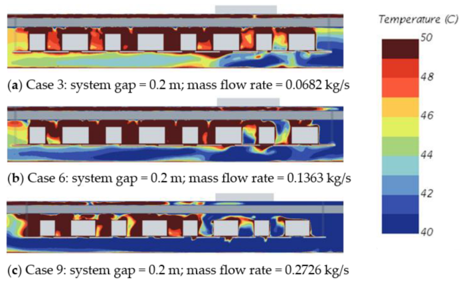
The previous paragraphs highlight the scenarios where the radiative heat exchanges prevail. In this last paragraph, the discussions will focus on the thermal environment of the three cases with the highest radiative heat flux ratio.
Figure 17 shows the temperature contour for cases 3, 6, and 9. These cases have all the maximum gap distance considered in this study, which shows that the gap distance plays a major role in the radiation exchange. However, the temperature contours show that the mass flow rate has a non-negligible effect on the system’s thermal environment, even though convective effects are less dominant than radiation. When the mass flow rate increases, the inlet flow reaches more systems downstream (Group 2). However, the four systems from Group 1 (Left part of the bay in
Figure 17), which have the highest radiative heat flux ratio, have the hottest environment for all inlet flow rate values.
4. Conclusions and Axes for Future Work
This paper investigates the influence of radiation on the overall system heat dissipation in two representative underfloor equipment bays of commercial and business aircraft. The authors use CFD simulations to demonstrate that heat radiation might significantly impact the equipment’s thermal environment.
A first case study dealing with a simplified cockpit underfloor equipment bay demonstrates that radiation exchange represents 50% of the overall heat flux dissipated by a system in its environment. Thus, radiation must be considered when studying an avionics thermal environment.
Then, a parametric study conducted in a generic but representative cabin underfloor equipment bay investigates the effects of ventilation flow rates and gap distances between adjacent systems on radiation magnitudes. The first outcome of this study is that the inlet mainstream flow affects the extent of radiation effects. Thus, the systems are grouped based on their relative location with regard to the inlet flow sources. Secondly, the authors analyze the sensitivity of system radiation heat flux with the gap distance between adjacent systems. Increasing the distance between two adjacent systems leads to higher radiative heat flux dissipation. On the other hand, increasing the inlet mass flow rate increases the convective heat exchange, thus reducing the radiative heat flux dissipated by the systems.
In summary, this paper’s results suggest that the radiative effects must be considered when:
The gap distance between the systems is larger than 0.1 m;
The flow rate between two systems is not strong enough to have high convective heat exchanges;
The systems of interest are hidden by other systems from the ventilation sources;
The systems of interest have significant internal heat dissipation.
Concluding, the results of the paper are important for aircraft manufacturers and system designers to focus on the type and depth of thermal analysis in early design phases.
Within this paper, the authors focus on a qualitative approach to assess the effects of the ventilation flow rate of an equipment bay and the gap distance between the systems on the radiation magnitude. Future work will focus on a quantitative assessment, which requires more extensive and detailed radiation calculations of radiation impacts on cooling system requirements of aircraft equipment bays. It is also expected that the contribution of the radiative cooling will decrease with the avionics box’s heat dissipation if the avionics box is internally ventilated. In this paper, the avionic boxes considered were sealed and cooled solely by their surfaces. Therefore, future work should address more extensive parametric studies dealing with system heat loads and wall and inlet temperatures to cover more aircraft operating conditions and other types of systems (e.g., different types of avionics boxes, batteries, hot air ducts, or motors) relevant for future aircraft featuring significant thermal challenges.
This extensive study, combined with the presented paper’s results, will allow for the derivation analytical correlations suitable for aircraft conceptual design, in particular, to enhance the previously developed thermal risk analysis (TRA). Those correlations will also indicate when it is necessary to include radiation in the cooling model for more advanced thermal analyses. Thus, with representative and easily usable correlations, conceptual aircraft designers will benefit from the guidelines and results presented in this paper to consider radiation when optimizing aircraft thermal management.
Overall, this paper’s results will contribute to enhance conceptual design methods, such as the TRA, and help optimizing thermal analysis and management strategies for future aircraft.
Author Contributions
Conceptualization, F.S. and S.L.-H.; methodology, F.S. and S.L.-H.; validation, F.S., S.L.-H. and T.B.; formal analysis, T.B.; investigation, T.B.; resources, S.L.-H.; data curation, T.B.; writing—original draft preparation, F.S., S.L.-H. and T.B.; writing—review and editing, S.L.-H.; visualization, F.S., S.L.-H. and T.B.; supervision, S.L.-H.; project administration, S.L.-H.; funding acquisition, S.L.-H. All authors have read and agreed to the published version of the manuscript.
Funding
This research was funded by the Natural Sciences and Engineering Research Council of Canada (NSERC), Grant Numbers CRDPJ 538897-19 and R.G.P.I.N./5515-2019, the Consortium de recherche et d’innovation en aérospatiale au Québec (CRIAQ), and Bombardier. The funding was attributed in the context of a collaboration with the project AGILE4.0 (Towards Cyber-physical Collaborative Aircraft Development), which is funded by the European Union Horizon 2020 Program under grant agreement no 815122.
Institutional Review Board Statement
Not applicable.
Informed Consent Statement
Not applicable.
Data Availability Statement
The data presented in this study are available on request from the corresponding author.
Acknowledgments
The authors acknowledge the contribution of Sebastien Beaulac from Bombardier, who provided valuable inputs during the study design and the analysis of the results.
Conflicts of Interest
The authors declare no conflict of interest. Bombardier, as one of the funders, advised in the study’s design and the interpretation of data; they also reviewed the results before publication.
Appendix A
Figure A1.
Velocity magnitude contour for all studied cases of Configuration 2.
Figure A1.
Velocity magnitude contour for all studied cases of Configuration 2.
Figure A2.
System temperature contour for all studied cases of Configuration 2.
Figure A2.
System temperature contour for all studied cases of Configuration 2.
Table A1.
System radiative heat fluxes for all studied cases of Configuration 2.
Table A1.
System radiative heat fluxes for all studied cases of Configuration 2.
| | | Total Heat Flux [W/m2] | Radiative Heat Flux
[W/m2] |
|---|
| System | Type | Heat load/Area | Case 1 | Case 2 | Case 3 | Case 4 | Case 5 | Case 6 | Case 7 | Case 8 | Case 9 |
| 1 | 3 MCU | 858.1 | 450.8 | 487.2 | 510.8 | 435.2 | 460.1 | 497.1 | 407.2 | 441.3 | 469.4 |
| 2 | 5 MCU | 1028.0 | 534.7 | 588.0 | 643.4 | 525.3 | 558.8 | 614.7 | 503.5 | 538.2 | 560.4 |
| 3 | 3 MCU | 858.1 | 370.5 | 428.9 | 484.9 | 356.2 | 408.4 | 475.3 | 317.9 | 374.9 | 430.6 |
| 4 | 5 MCU | 1028.0 | 529.7 | 563.6 | 636.4 | 509.9 | 540.1 | 612.2 | 446.3 | 491.8 | 556.0 |
| 5 | 3 MCU | 858.1 | 357.7 | 416.6 | 464.4 | 350.4 | 392.4 | 462.1 | 276.5 | 325.0 | 388.7 |
| 6 | 5 MCU | 1028.0 | 505.0 | 576.3 | 611.7 | 490.9 | 535.1 | 564.6 | 418.3 | 450.1 | 462.1 |
| 7 | 3 MCU | 858.1 | 352.3 | 391.6 | 437.7 | 341.6 | 393.8 | 436.0 | 305.5 | 353.9 | 357.1 |
| 8 | 5 MCU | 1028.0 | 599.1 | 617.5 | 610.8 | 538.6 | 575.5 | 583.9 | 506.0 | 494.5 | 502.3 |
| 9 | 3 MCU | 858.1 | 454.9 | 478.0 | 505.0 | 439.7 | 451.7 | 484.4 | 403.0 | 444.8 | 473.2 |
| 10 | 5 MCU | 1028.0 | 535.5 | 583.7 | 636.7 | 521.0 | 552.8 | 613.2 | 488.9 | 526.1 | 576.3 |
| 11 | 3 MCU | 858.1 | 369.3 | 427.5 | 477.1 | 357.3 | 420.9 | 471.2 | 337.9 | 377.6 | 439.7 |
| 12 | 5 MCU | 1028.0 | 531.5 | 579.1 | 626.8 | 526.2 | 542.7 | 608.9 | 426.1 | 509.0 | 545.0 |
| 13 | 3 MCU | 858.1 | 367.3 | 420.5 | 477.1 | 341.6 | 380.4 | 448.8 | 272.2 | 321.8 | 401.5 |
| 14 | 5 MCU | 1028.0 | 515.1 | 545.3 | 615.8 | 504.1 | 510.5 | 565.5 | 416.1 | 429.7 | 455.1 |
| 15 | 3 MCU | 858.1 | 352.9 | 392.2 | 441.5 | 329.6 | 374.9 | 428.6 | 303.5 | 333.2 | 383.1 |
| 16 | 5 MCU | 1028.0 | 599.8 | 595.4 | 609.2 | 533.3 | 576.7 | 588.2 | 493.6 | 483.0 | 521.5 |
References
- van Heerden, A.S.J.; Judt, D.M.; Jafari, S.; Lawson, C.P.; Nikolaidis, T.; Bosak, D. Aircraft Thermal Management: Practices, Technology, System Architectures, Future Challenges, and Opportunities. Prog. Aerosp. Sci. 2022, 128, 100767. [Google Scholar] [CrossRef]
- Kühn, M.; Bosbach, J.; Wagner, C. Experimental Parametric Study of Forced and Mixed Convection in a Passenger Aircraft Cabin Mock-Up. Build. Environ. 2009, 44, 961–970. [Google Scholar] [CrossRef]
- Bianco, V.; Manca, O.; Nardini, S.; Roma, M. Numerical Investigation of Transient Thermal and Fluidynamic Fields in an Executive Aircraft Cabin. Appl. Therm. Eng. 2009, 29, 3418–3425. [Google Scholar] [CrossRef] [Green Version]
- Geron, M.; Butler, C.; Stafford, J.; Newport, D. Development and Validation of a Compact Thermal Model for an Aircraft Compartment. Appl. Therm. Eng. 2013, 61, 65–74. [Google Scholar] [CrossRef] [Green Version]
- Butler, C.; Newport, D.; Geron, M. Optimising the Locations of Thermally Sensitive Equipment in an Aircraft Crown Compartment. Aerosp. Sci. Technol. 2013, 28, 391–400. [Google Scholar] [CrossRef]
- Butler, C.; Newport, D. Experimental and Numerical Analysis of Thermally Dissipating Equipment in an Aircraft Confined Compartment. Appl. Therm. Eng. 2014, 73, 869–878. [Google Scholar] [CrossRef]
- Lawson, C.P.; Pointon, J.M. Thermal Management of Electromechanical Actuation on an All-Electric Aircraft. In Proceedings of the 26th International Congress of Aeronautical Sciences, ICAS-2008-6.6, Anchorage, Alaska, 14–19 September 2008. [Google Scholar]
- McCarthy, K.; Heltzel, A.; Walters, E.; Roach, J.; Iden, S.; Lamm, P. A Reduced-Order Enclosure Radiation Modeling Technique for Aircraft Actuators. In SAE Technical Papers 2010-01-1741; SAE International: Warrendale, PA, USA, 2010. [Google Scholar] [CrossRef]
- Sanchez, F.; Delbecq, S. Surrogate Modeling Technique for the Conceptual and Preliminary Design of Embedded Actuation Systems and Components. In Proceedings of the 30th Congress of the International Council of the Aeronautical Sciences, Daejeon, Republic of Korea, 25 September 2016; p. 11. [Google Scholar]
- Yetik, O.; Karakoc, T.H. Thermal Management System with Nanofluids for Hybrid Electric Aircraft Battery. Int. J. Energy Res. 2021, 45, 8919–8931. [Google Scholar] [CrossRef]
- Sanchez, F.; Liscouët-Hanke, S.; Boutin, Y.; Beaulac, S.; Dufresne, S. Multi-Level Modeling Methodology for Aircraft Thermal Architecture Design. In SAE Technical Paper 2018-01-1910; SAE International: Warrendale, PA, USA, 2018. [Google Scholar] [CrossRef]
- Sanchez, F.; Liscouët-Hanke, S. Thermal Risk Prediction Methodology for Conceptual Design of Aircraft Equipment Bays. Aerosp. Sci. Technol. 2020, 104, 105946. [Google Scholar] [CrossRef]
- Sanchez, F.; Huzaifa, A.M.; Liscouët-Hanke, S. Ventilation Considerations for an Enhanced Thermal Risk Prediction in Aircraft Conceptual Design. Aerosp. Sci. Technol. 2021, 108, 106401. [Google Scholar] [CrossRef]
- Bhise, T.; Sanchez, F.; Liscouët-Hanke, S. Systems Radiation Consideration for Thermal Risk Assessment of Avionics Bays in Conceptual Design. In Proceedings of the CASI AERO Conference, Online, 14 June 2021. [Google Scholar]
- Ezzaraa, K.; Bahlaoui, A.; Arroub, I.; Raji, A.; Hasnaoui, M.; Naïmi, M. Radiation Effect on Mixed Convection Cooling in a Ventilated Horizontal Cavity with Multiple Ports. Int. J. Mech. Sci. 2019, 153–154, 310–320. [Google Scholar] [CrossRef]
- Airbus Airport Operations—AutoCAD 3 View Aircraft Drawings. Available online: https://www.airbus.com/en/airport-operations-and-technical-data/airport-operations-autocad-3-view-aircraft-drawings (accessed on 2 November 2022).
- DO-160G, R. RTCA DO-160G for Airborne Equipment | DO-160. Available online: https://do160.org/rtca-do-160g/ (accessed on 20 May 2021).
- Bombardier Bombardier Global Express—Integrated Air Management System. Bombard. Glob. Express 2012. Available online: https://www.smartcockpit.com/docs/Global_Express-Integrated_Air_Management_System.pdf (accessed on 20 October 2022).
- Bombardier Bombardier Global—Airplane Genaral. Bombard. Glob. 2005. Available online: https://www.smartcockpit.com/docs/Airplane_General.pdf (accessed on 20 October 2022).
- MIL-STD-1472 G; Design Criteria for Human Engineering. Department of Defense: Arlington, VA, USA, 2019. Available online: https://govtribe.com/file/government-file/fa86291995012-mil-std-1472g-human-engineering-17-jan-2019-dot-pdf (accessed on 3 November 2022).
- Yuce, B.E.; Pulat, E. Forced, Natural and Mixed Convection Benchmark Studies for Indoor Thermal Environments. Int. Commun. Heat Mass Transf. 2018, 92, 1–14. [Google Scholar] [CrossRef]
- Boussinesq, J. Théorie Analytique de La Chaleur; Faculté des sciences de l’université de Paris: Paris, France, 1903; Volume 2. [Google Scholar]
- Siegel, R.; Howell, J.R. Thermal Radiation Heat Transfer, 3rd ed.; Hemisphere Publishing Co.: Washington, DC, USA, 1992. [Google Scholar]
- Holman, J.P. Heat Transfer, 8th SI Metric ed.; McGraw Hill: New York, NY, USA, 2001. [Google Scholar]
- Roache, P.J. Quantification of Uncertainty in Computational Fluid Dynamics. Annu. Rev. Fluid Mech. 1997, 29, 123–160. [Google Scholar] [CrossRef]
Figure 1.
Aircraft avionics bay configurations for the investigation of the thermal radiation aspect.
Figure 1.
Aircraft avionics bay configurations for the investigation of the thermal radiation aspect.
Figure 2.
Cockpit underfloor equipment bay in a larger commercial aircraft and derived simplified bay model with three cubic-shaped systems (Configuration 1).
Figure 2.
Cockpit underfloor equipment bay in a larger commercial aircraft and derived simplified bay model with three cubic-shaped systems (Configuration 1).
Figure 3.
Simplified cockpit underfloor equipment bay with dimensions and air-inlet and outlet locations (Sys1, Sys2, and Sys3 refer to System 1, System 2, and System 3).
Figure 3.
Simplified cockpit underfloor equipment bay with dimensions and air-inlet and outlet locations (Sys1, Sys2, and Sys3 refer to System 1, System 2, and System 3).
Figure 4.
Mesh used in the CFD model for configuration 1.
Figure 4.
Mesh used in the CFD model for configuration 1.
Figure 5.
Cabin underfloor equipment bay in a business jet and derived simplified bay model with 16 cubic-shaped systems (Configuration 2).
Figure 5.
Cabin underfloor equipment bay in a business jet and derived simplified bay model with 16 cubic-shaped systems (Configuration 2).
Figure 6.
Geometrical description of the cabin underfloor equipment bay (Configuration 2).
Figure 6.
Geometrical description of the cabin underfloor equipment bay (Configuration 2).
Figure 7.
Mesh of the CFD model of configuration 2.
Figure 7.
Mesh of the CFD model of configuration 2.
Figure 8.
System surface temperature contours and velocity streamlines for the cockpit underfloor equipment bay (Configuration 1).
Figure 8.
System surface temperature contours and velocity streamlines for the cockpit underfloor equipment bay (Configuration 1).
Figure 9.
Cross-sectional view (centered on Outlet 1) of the air temperature for the cockpit underfloor equipment bay (Configuration 1).
Figure 9.
Cross-sectional view (centered on Outlet 1) of the air temperature for the cockpit underfloor equipment bay (Configuration 1).
Figure 10.
Cross-sectional view (Centered on Outlet 1) of the velocity magnitude contour for the cockpit underfloor equipment bay (Configuration 1).
Figure 10.
Cross-sectional view (Centered on Outlet 1) of the velocity magnitude contour for the cockpit underfloor equipment bay (Configuration 1).
Figure 11.
Side view of the underfloor equipment bay (Configuration 2).
Figure 11.
Side view of the underfloor equipment bay (Configuration 2).
Figure 12.
Velocity streamlines from inlets 1, 2, and 3 for the underfloor equipment bay (Configuration 2).
Figure 12.
Velocity streamlines from inlets 1, 2, and 3 for the underfloor equipment bay (Configuration 2).
Figure 13.
Evolution of the radiative heat flux ratio with system gap distance for different inlet mass flow rates (Configuration 2).
Figure 13.
Evolution of the radiative heat flux ratio with system gap distance for different inlet mass flow rates (Configuration 2).
Figure 14.
Velocity contour for Cases 1, 2, and 3 of the underfloor equipment bay (Configuration 2) for increasing gap distances and a constant mass flow rate.
Figure 14.
Velocity contour for Cases 1, 2, and 3 of the underfloor equipment bay (Configuration 2) for increasing gap distances and a constant mass flow rate.
Figure 15.
Evolution of radiative heat flux ratio with inlet mass flow rate for different system gap distances (Configuration 2).
Figure 15.
Evolution of radiative heat flux ratio with inlet mass flow rate for different system gap distances (Configuration 2).
Figure 16.
Velocity contours for Cases 2, 5, and 8 of the underfloor equipment bay (Configuration 2) for increasing mass flow rates and a constant system gap.
Figure 16.
Velocity contours for Cases 2, 5, and 8 of the underfloor equipment bay (Configuration 2) for increasing mass flow rates and a constant system gap.
Figure 17.
Air temperature contour for Cases 3, 6, and 9 of the underfloor equipment bay (Configuration 2) when radiative effects are dominating.
Figure 17.
Air temperature contour for Cases 3, 6, and 9 of the underfloor equipment bay (Configuration 2) when radiative effects are dominating.
Table 1.
Boundary conditions for the cockpit underfloor equipment bay (Configuration 1).
Table 1.
Boundary conditions for the cockpit underfloor equipment bay (Configuration 1).
| Entity | Boundary Condition | Physics Value |
|---|
| Inlet 1 and Inlet 2 | Mass Flow Inlet | 0.0191 kg/s at 30 °C |
| Outlet 1 and Outlet 2 | Pressure Outlet | Split Ratio 0.5 |
| Bay Left Wall | Adiabatic | - |
| Bay Right Wall | Constant Temperature | 55 °C |
| Bay Top Wal | Constant Temperature | 30 °C |
| Bay Bottom Wall | Constant Temperature | 55 °C |
| Bay Front Wall | Constant Temperature | 55 °C |
| Bay Back Wall | Constant Temperature | 55 °C |
Table 2.
Parametric study for the cabin underfloor equipment bay (Configuration 2).
Table 2.
Parametric study for the cabin underfloor equipment bay (Configuration 2).
| Case | Mass Flow Rate (kg/s) | Gap (m) |
|---|
| | Inlet 1 (39%) | Inlet 2 (39%) | Inlet 3 (22%) | Total | |
| 1 | 0.0266 | 0.0266 | 0.0150 | 0.0682 | 0.05 |
| 2 | 0.0266 | 0.0266 | 0.0150 | 0.0682 | 0.1 |
| 3 | 0.0266 | 0.0266 | 0.0150 | 0.0682 | 0.2 |
| 4 | 0.0532 | 0.0532 | 0.0300 | 0.1363 | 0.05 |
| 5 | 0.0532 | 0.0532 | 0.0300 | 0.1363 | 0.1 |
| 6 | 0.0532 | 0.0532 | 0.0300 | 0.1363 | 0.2 |
| 7 | 0.1063 | 0.1063 | 0.0600 | 0.2726 | 0.05 |
| 8 | 0.1063 | 0.1063 | 0.0600 | 0.2726 | 0.1 |
| 9 | 0.1063 | 0.1063 | 0.0600 | 0.2726 | 0.2 |
Table 3.
Boundary conditions for the CFD study of the cabin underfloor equipment bay (Configuration 2).
Table 3.
Boundary conditions for the CFD study of the cabin underfloor equipment bay (Configuration 2).
| Entity | Boundary Condition | Physics Value |
|---|
| Aft Cabin Wall | Constant Temperature | 55 °C |
| Bay Bottom Wall | Constant Temperature | 55 °C |
| Catwalk | Adiabatic | - |
| Inlet 1 | Mass Flow Inlet | Case dependent |
| Inlet 2 | Mass Flow Inlet | Case dependent |
| Inlet 3 | Mass Flow Inlet | Case dependent |
| Outlet | Pressure Outlet | Split Ratio 1 |
| Supply Duct | Constant Temperature | 30 °C |
| Supporting Rack | Adiabatic | - |
| Bay Top Wall | Constant Temperature | 30 °C |
Table 4.
System surface-averaged temperature and radiative heat flux for Configuration 1.
Table 4.
System surface-averaged temperature and radiative heat flux for Configuration 1.
| System | Without Radiation | With Radiation |
|---|
| | Temperature (°C) | Temperature (°C) | Radiative Heat Flux Ratio |
| System 1 | 125.9 | 83.6 | 0.49 |
| System 2 | 135.9 | 90.0 | 0.47 |
| System 3 | 133.2 | 81.9 | 0.50 |
| Publisher’s Note: MDPI stays neutral with regard to jurisdictional claims in published maps and institutional affiliations. |
© 2022 by the authors. Licensee MDPI, Basel, Switzerland. This article is an open access article distributed under the terms and conditions of the Creative Commons Attribution (CC BY) license (https://creativecommons.org/licenses/by/4.0/).


