Article

Bio-Inspired Self-Organized Fission–Fusion Control Algorithm for UAV Swarm

1
School of Electronic Information Engineering, Beihang University, Beijing 100191, China
2
Shen Yuan Honors College, Beihang University, Beijing 100191, China
3
Institute of Unmanned System, Beihang University, Beijing 100191, China
*
Author to whom correspondence should be addressed.
Aerospace 2022, 9(11), 714; https://doi.org/10.3390/aerospace9110714
Submission received: 30 August 2022 / Revised: 8 November 2022 / Accepted: 9 November 2022 / Published: 12 November 2022

Abstract

:
Swarm control has become a challenging topic for the current unmanned aerial vehicle (UAV) swarm due to its conflicting individual behaviors and high external interference. However, in contrast to static obstacles, limited attention has been paid to the fission–fusion behavior of the swarm against dynamic obstacles. In this paper, inspired by the interaction mechanism and fission–fusion motion of starlings, we propose a Bio-inspired Self-organized Fission–fusion Control (BiSoFC) algorithm for the UAV swarm, where the number of UAVs in the sub-swarm is controllable. It solves the problem of swarm control under dynamic obstacle interference with the tracking function. Firstly, we establish the kinematic equations of the individual UAV and swarm controllers and introduce a fission–fusion control framework to achieve the fission–fusion movement of the UAV swarm with a lower communication load. Afterward, a sub-swarm selection algorithm is built upon the topological interaction structure. When a swarm is faced with different tasks, the swarm that can control the number of agents in a sub-swarm can accomplish the corresponding task with a more reasonable number of agents. Finally, we design a sub-swarm trapping algorithm with a tracking function for the dynamic obstacles. The simulation results show that the UAV swarm can self-organize fission sub-swarms to cope with dynamic obstacles under different disturbance situations, and successfully achieve the goal of protecting the parent swarm from dynamic obstacles. The experimental results prove the feasibility and effectiveness of our proposed control algorithm.

1. Introduction

Natural phenomena such as fish feeding, bird migration, and bat predation have provided evidence that animals in swarms are greater than the sum of their individual parts [1,2,3,4]. The dynamic movement process of the swarm usually involves adding or reducing members, known as swarm fission–fusion [5].
The term “fission–fusion” was first proposed by Kummer et al. [6] to describe the phenomenon where nonhuman primates change their group size by fission–fusing subunits. Animal swarms in nature maximize the advantages of fission–fusion behaviors. For example, wide-nosed dolphins improve the success rate of prey roundup [7,8,9], groups of spider monkeys and sheep enhance foraging efficiency [5,10], and flocks of birds avoid predators [11] through fission–fusion. In recent years, researchers have applied the concept of the fission–fusion of living organisms in other fields, such as intelligent numerical optimization [12,13,14,15], UAV swarm motion [16,17,18], and power control [19,20]. Bansal et al. [13] proposed the spider monkey optimization (SMO) algorithm by studying the fission–fusion phenomena spider monkeys’ foraging. Liang et al. [17] introduced the idea of biological fission–fusion to the interaction topology of an underwater vehicle (UUV). Aureli et al. [19] extended the concept of fission–fusion to the dynamics control architecture.
Most of the works over the last decades mainly focus on the basic flocking behavior, where agents within a specific range can be gathered into a group with the same state of motion through interactions. For this problem, Reynolds [21] introduced the basic heuristic rules (cohesion, separation, and alignment) in the field of swarm control, and numerous swarm control methods have been proposed successively [15,22,23], such as the artificial potential field [22], virtual physics [15], and geometric class [23] methods. Researchers have also investigated the self-organized fission–fusion behavior of swarms lately and promoted the development of related fields. For example, Lei et al. [24] proposed a fission–fusion swarm method based on the neighboring domain, Yang et al. [25] presented a self-organizing fission–fusion method based on intermittent selective interaction, and You et al. [26] utilized the task-driven ideas to achieve a fission–fusion swarm of UAVs. Nevertheless, most of these studies concentrated on the collision avoidance of the single swarm and static obstacles by fission. The swarm fission–fusion motion control in dynamic obstacle environments is insufficiently conducted. Additionally, obstacles or attackers typically interfere with the swarm in the form of random or even tracking dynamics, which could seriously disrupt the movement of the swarm. Therefore, swarm control which relies on the continuous fission–fusion is of significant interest to avoid the successive aggression of dynamic obstacles.
In addition, the interaction structure of most existing fission–fusion algorithms is often implemented as a fixed distance [24,25,26], whose number depends on how many neighbors are present within the range. The assumption above differs from the way species interact in the biological world. In the natural swarm, the large-scale swarm is accomplished by interacting with a limited number of members [25,27,28,29]. Researchers found that the interaction structure of starling flocks is topological and the distance of the interaction structure is unfixed [29]. Each starling only interacts with its nearest six to seven neighbors, and the distance between agents does not affect the interaction distance [29]. Additionally, starlings rely on the six or seven neighbors to interact with the swarm in a topological way, eventually achieving the communication of a huge swarm with thousands of members, and the distance between members does not affect the interaction distance. Based on this finding, researchers have conducted numerous studies and exploited the behavior of starling swarms [30,31]. Recently, Ourari et al. [32] applied the topology of the starling to the collision avoidance of UAV swarms with the reinforcement learning method.
In this paper, inspired by the topological characteristics of starling flocks with the basic three rules [21], we propose a Bio-inspired Self-organized Fission–fusion Control (BiSoFC) algorithm for the UAV swarm with a controllable number of UAVs in the sub-swarm. We first establish the self-organized fission–fusion control framework by combing it with the starling topology and formulate the kinematic equations of the UAV and swarm controller. Then, the interaction structure of starlings is applied in the sub-swarm selection algorithm, and the problem that the number of sub-swarm members cannot be controlled in the existing algorithm is solved. We further design the dynamic obstacle trapping algorithm for different interference cases of dynamic obstacles which have tracking functions. This scheme achieves the self-organized trapping of dynamic obstacles by the sub-swarm to prevent the parent swarm from being disturbed by dynamic obstacles. Meanwhile, the sub-swarm can self-organize to return to the parent swarm for integration after completing trapping. The simulation experiments demonstrate the feasibility and effectiveness of the proposed algorithm:
  • Inspired by the topological interaction structure of starling, we design a self-organized fission–fusion control framework for the UAV swarm and establish the kinematic model of the UAVs as well as the UAV swarm controller.
  • Based on the topological interaction structure of starlings, we introduce a sub-swarm selection algorithm to control the number of agents in the sub-swarm.
  • We present a sub-swarm trapping algorithm for different interference situations of dynamic obstacles with a tracking function.
  • We illustrate the feasibility and effectiveness of our proposed control method by numerical simulations, which include the conditions of differentiation index, polarization index, the precision of response stimuli, and communication load.
The remainder of this paper is organized as follows:
Section 2 analyzes the existing swarm dynamics model to establish the UAV swarm agent kinematic model of the UAV and UAV swarm controller. In Section 3, the starling topological interaction structure is modeled, and the UAV swarm self-organized fission–fusion swarm control framework is proposed. Section 4 uses a sub-swarm selection algorithm based on the starling topological interaction structure. A sub-swarm trapping algorithm is intended for different interference cases of dynamic obstacles with a tracking function. In Section 5, we simulate the proposed bio-inspired self-organized fission–fusion swarm algorithm for the UAV swarm with a controllable number of UAVs in the sub-swarm and establish the evaluation index to analyze the effectiveness of the algorithm. Finally, a conclusion is given in Section 6.

2. Problem Formulation

2.1. Traditional Model for UAV Cluster Dynamics

Consider two swarm systems g sub swarm ,   parent swarm , which consist of a total of N agents. The swarm moves in a three-dimensional space without boundary constraints. It is worth noting that although the two swarms are referred to as sub-swarm and parent swarm, the two swarms are equal and independent, have no leading role in each other, and can accomplish different respective tasks. The following double integrator controls the motion of the agent:
χ ˙ i g = v i g m i g v ˙ i g = u i g ξ v i g 2 v i g + ζ ϑ i g
where χ i g = x i g , y i g , h i g R 3 is the position of agent i in g [sub-swarm, parent-swarm], v i g R n is the velocity vector, u i g R n is the control input acting on it, m i g denotes its quality, ξ v i g 2 v i g is friction with the environment, ξ is the environmental damping factor, ζ ϑ i g is a random noise of the environment with an intensity equal to ζ , and ϑ i g 0 , 1 is a uniformly distributed random vector. According to the existing literature, most of the internal interactions between agents follow the cohesion alignment [22] and the separation rules [21]. A typical implementation is as follows:
u i g = γ i n e v i g + u i g p o s + u i g v e l + u i g g u i + ξ v i g 2 v i g
where γ i n e is the inertia coefficient, u i g p o s is the position cooperation term of agent i in g . u i g v e l is the velocity alignment term of agent i in g , u i g g u i is the navigation function term of agent i in g , and u i g g u i is set to ( 1 , 1 , 0 )T for ease of observation.
Defining u i g p o s as follows:
u i g p o s = 1 N i g j N i g t Γ p o s ( 1 ( l a g d i j g ) 2 ) exp ( l c g d i j g ) x j g x i g x j g x i g
where Γ g p o s is the parameter of position cooperation in g , l a g is the desired spacing of agents in g , l c g is the decay coefficient of agents in g , x i g is agent i spacing position in g , d i j g represents the actual distance between agent i and agent j in g , N i g is the number of interacting agents with agent i in g , and N i g t is the set of neighbors in g that interact with agent i at the moment t .
The traditional definition of u i g v e l is as follows:
u i g v e l = 1 N i g j N i g ( t ) Γ v e l ( v j g v i g )
where Γ g v e l is the parameter of u i g v e l .
The action of Equation (4) is the famous “velocity consensus” algorithm. The swarm can quickly achieve speed convergence to a consistent state through Equation (4) [21]. However, if only a few agents in the swarm recognize the obstacle, the swarm using Equation (4) cannot achieve self-organized fission movement [33]. Yang accomplished a self-organized fission–fusion movement for a static obstacle swarm by introducing an attention mechanism [16]. However, the existing methods for dynamic obstacles with tracking capabilities often reduce the mission completion efficiency of the UAV swarm (e.g., Figure 1a,b) and even fail to complete the original mission results, (e.g., Figure 1c,d).
Therefore, a new control algorithm for self-organized splitting and merging of UAV swarms in a three-dimensional space in a lightweight and low communication cost manner is necessary, which is an extension of the traditional velocity alignment [22]. A sub-swarm selection algorithm is proposed to realize the fission–fusion movement of the UAV swarm in a more flexible way that can control the number of agents in the sub-swarm. Meanwhile, for dynamic obstacles with the tracking function, a sub-swarm trapping algorithm is proposed to ensure that the sub-swarm can trap the dynamic obstacles again self-organized when the dynamic obstacles are tracked during the tracking process of the mother swarm, to achieve the goal of protecting the mother swarm from interference.

2.2. UAV Kinematic Model

Assuming that the UAV is configured with a three-loop self-pilot for velocity, heading angle, and altitude, the UAV kinematic model can be simplified [34] as follows:
x ˙ i g = v i g cos ψ i g y ˙ i g = v i g sin ψ i g ψ ˙ i g = 1 α ψ ( ψ i g i n p ψ i g ) v ˙ i g = 1 α v ( v i g i n p v i g ) h ¨ i g = v i g 1 α h ˙ h ˙ i g + 1 α h ( h i g i n p h i g )
where ( x i g , y i g , h i g ) is the position of agent i in g sub swarm , parent swarm . v i g i n p , Ψ i g i n p and h i g i n p , respectively, denote the horizontal speed, altitude, and heading angle control input commands of agent i in g , v i g , ψ i g , and h ˙ i g represent the horizontal velocity, heading angle, and altitude change rate of agent i in g . α ψ , α v , α h and α h ˙ are self-driving instrument control parameters.
The UAV flight condition constraints are considered as follows:
v min < v i g < v max χ ˙ φ max g v i g min < h ˙ i g < max
where v min , v max , φ max , and max are representing the minimum horizontal speed, maximum horizontal speed, maximum lateral overload, maximum height, and change rate and all are greater than zero, min is the minimum height change rate, and g represents the acceleration of gravity.

2.3. Model Relationship between UAV Cluster Controller and UAV Kinematic Model

The control input u i g solved by the command to obtain the autopilot control input for agent i in g . The definitions are as follows:
u i g = u i g x u i g y u i g h
v i g i n p = α v ( u i g x cos ψ i g + u i g y sin ψ i g ) + v i g ψ i g i n p = α ψ v i g ( u i g x cos ψ i g u i g y sin ψ i g ) + ψ i g h i g i n p = h i + α h α h ˙ h ˙ i g + α h u i g h
where u i g x , u i g y , and u i g h are the swarm control quantities in the x-axis, y-axis, and altitude direction of agent i in the inertial coordinate system, respectively.
The state output values of the UAV dynamics model can be converted into UAV position and velocity vectors as the inputs to the UAV swarm controller, which are as follows:
x i g = ( x i g , y i g , h i g ) v i g = ( v i g cos ψ i g , v i g sin ψ i g , h ˙ i g )

3. Bio-Inspired Self-Organized Fission–Fusion Control Framework

In this section, to reduce the enormous communication load is of the self-organized fission–fusion. A bio-inspired self-organized fission–fusion swarm algorithm for the UAV swarm based on the traditional framework [22] is proposed for the UAV swarm.

3.1. Starling Topological Interaction Algorithm

In practice, the interaction structure with all members of a fixed distance as neighbors usually generates a huge communication load, which is one reason for achieving a large-scale swarm of the UAV swarm during practical use. Therefore, to reduce the communication pressure between UAV swarms, inspired by the flutter interaction structure of the starling flock [29], the topological interaction structure of the starling flock is adopted for the selection of the interaction mechanism of agents and the maximum number of interacting neighbors is set to seven [29]. The set of agent interaction neighbors is represented as follows:
N i g t = j | min p u d i j g , d i j g < R Radius , j = 1 , 2 , 3 , , N G g , j i , u 7
d i j g = x i g x j g
where d i j g represents the actual distance between agent i and agent j in g , N G g is the number of drones in g, and j is the agent that establishes interaction with the agent i . We consider that each agent has the same perceptual radius R R a d i u s . It is worth noting that in the usual case, most of the interaction structures use fixed-distance interaction structures, which are shown in Figure 2a. The Boids model [21], the Couzin model [35], and the Vicsek model [36] all use a fixed-distance interaction structure. In these fixed-distance interaction structures, where the interaction radius σ i is the same as the perception radius R R a d i u s , the R R a d i u s is the maximum Euclidean distance that the agent can perceive. In this paper, the perception radius R R a d i u s is the same as the one in the fixed-distance interaction structure. However, in Figure 2b, the interaction radius σ i is different from the one in the fixed-distance interaction structure. The interaction radius σ i is smaller than the R R a d i u s in such a condition. The feature above is common in the interaction structure of starlings [29]. Therefore, the σ i of the agent in a dense UAV swarm is often much smaller than the R R a d i u s , and the differences are shown in Figure 2. The topological interaction structure is more economical regarding swarm communication resources than the fixed-distance interaction structure, which will be verified in the subsequent simulation experiments.

3.2. UAV SWARM Self-Organized Fission–Fusion Control Framework

The behavior of fission–fusion of a UAV swarm is usually two competing behaviors. UAV fusion behavior requires a highly ordered group among the agents. The fission behavior demands a break in the original orderliness between agents splitting into multiple smaller swarms [5,19].
The effect of dynamic obstacles on the swarm is added to the control algorithm in the form of intrusive forces. The control algorithm for self-organized fission–fusion is defined as follows:
χ ˙ i g = v i g m i g v ˙ i g = γ i n e v i g + u i g p o s + i g u i g g u i + u i g v l l + 1 i g u invaders u i g v e l ξ v i g 2 v i g + ζ ϑ i g u ζ g e n v
where γ i n e is the inertia coefficient, γ i n e v i g is the inertial force of the agent i , u i g p o s is the position cooperation of agent i in g , and u i g v e l is the interaction velocity alignment of agent i in g . The influence of crosswinds are very important in the flight of UAVs [37,38]. Therefore, we define the random noise ζ ϑ i g of the environment specifically as the influence of a random crosswind u ζ g e n v in the environment. The spatial distribution among agents in each UAV swarm is achieved by Equation (3). A velocity alignment based on Equation (4) is proposed for dynamic obstacles:
u i g v e l = 1 N i g j N i g t Γ v e l v j g v i g + 1 i g u t r a p p i n g + u l u r e u invaders
where u l u r e is the induced force generated by the dynamic obstacles on the agent when the sub-swarm is trapped, u t r a p p i n g represents the intrusive force generated by a dynamic obstacle to the agent, and j g is the state indicator of whether agent j in the neighbor of agent i in g under the topological interaction structure requires fission movement as a sub-swarm member. The velocity algorithm for dynamic obstacles can achieve the effect of self-organized fission–fusion with a controllable number of sub-swarm when encountering dynamic obstacles.

4. Sub-Swarm Selection Algorithm and Sub-Swarm Induction Algorithm

To realize the UAV swarm fission–fusion movement for dynamic obstacles with tracking function and reduce the influence of dynamic obstacles on swarm movement. The sub-swarm selection algorithm and sub-swarm induction algorithm are proposed, which realize controllable fission motion with the number of agents in the sub-swarm self-organized induced movement against the interference of dynamic obstacles.

4.1. Sub-Swarm Selection Algorithm

Equation (10) shows that the agents of the swarm only interact with a limited number of neighbors. Algorithm 1 demonstrates the selection mechanism of the sub-swarm when fission behavior occurs, in which swarms are selected by constantly interacting topologically with surrounding agents to finally reach a sub-swarm selection result that can control the number of sub-swarms.
Algorithm 1 Sub-Swarm Selection Algorithm
input: x min g , N i g t
output: sub-swarm
function sub-swarm selection
  now-number 0
  if  x min g < R R a d i u s  then
   for i 1: flight-number do
    if now-number except-number then
     alter-sub-swarmi choose the x min g agent from N i g t
     if  φ i g 0  then
                φ i g = 0
      sub-swarm [1,now-number] alter-sub-swarmi
      now-number now-number + 1
     end if
     if now-number == except-number then
      break
     end if
     for j  1 : N i g t  do
     alter-sub-swarmj choose the x min g agent from N i g t
      if  φ i g 0  then
                φ i g = 0
       sub-swarm [1,now-number] alter-sub-swarmj
       now-number now-number + 1
      end if
      if now-number == except-number then
       break
      end if
     end for
    end if
   end for
  end if
  return sub-swarm
end function

4.2. Sub-Swarm Trapping Algorithm

After the fission behavior occurs, the sub-swarm will perform the corresponding trapping movements in response to the conduct of dynamic obstacles. Algorithm 2 shows the trapping algorithm of the sub-swarm intending to ensure that the parent swarm is not affected by the dynamic obstacle. The algorithm enables the sub-swarm to trap dynamic obstacles. If the moving obstacles re-track the parent swarm during trapping, the sub-swarm will self-organize to re-trap the dynamic obstacles. We propose to evaluate whether the sub-swarm trapping movement at the moment t is affected by the direction of motion of the agent, and the evaluation method is as follows:
Θ g = ( arccos ( x min g x i n v a d e r x min g x i n v a d e r ) t arccos ( x min g x i n v a d e r x min g x i n v a d e r ) t 1 )
Θ pargp Θ subgp = Θ pargp Θ pargp Θ subgp Θ subgp
where x min g is the position of the agent in g that is closest to the dynamic obstacle and x i n v a d e r represents the position vector of the dynamic obstacle.
Where ʑ i n d u c t i o n _ a r e a is the safe trapping range of the sub-swarm, and the sub-swarm within the safe trapping range flies to the pseudo-target point with randomness if the trapping is judged to be successful, and T testing _ thresholds is the judgment threshold. When the number of times ɵ p a r e n t s w a r m ɵ s u b s w a r m = = 1 is determined to be anomalous and exceeds a threshold, the sub-swarm determines that the dynamic obstacle is free from trapping.
Algorithm 2 Sub-Swarm Trapping Algorithm
input: x min g , N i g t , v i n v a d e r
output: utrapping, ulure
function sub-swarm trapping
   T testing _ cycle 0
  if x min g < R R a d i u s   then
   sub-swarm Algorithm 1
   if x min g   >   max ( ʑ induction _ area )   then
u l u r e x min s u b _ s w a r m x i n v a d e r x i n v a d e r x min s u b _ s w a r m + v g

   end if
   if x min g     ʑ i n d u c t i o n _ a r e a   then
u t r a p p i n g u g u i x i n v a d e r x min s u b _ s w a r m x i n v a d e r x min s u b _ s w a r m + k s u b _ s w a r m

   end if
   for i     1   :   T testing _ cycle   do
    if ɵ p a r e n t s w a r m ɵ s u b s w a r m = = 1   then
      T testing _ cycle     T testing _ cycle + 1
    end if
  When T testing _ cycle = = T testing _ thresholds
     u t r a p p i n g 16
  end for
  if ɵ i n v a d e r 0   and   v i n v a d e r 0   then
    φ j g = 0 , j     s u b s w a r m 1 , 2 , , , , e x c e p t _ n u m b e r
  end if
end if
  return u t r a p p i n g ,   u l u r e
end function

5. Simulation Studies

In this section, numerical simulation experiments are conducted to verify the feasibility and effectiveness of the proposed algorithm.

5.1. Swarm Campaign Evaluation Metrics

5.1.1. Order Parameters

The orderliness of cluster motion is usually described by order parameters according to Vicsek [39]. The polarization index and the differentiation index are utilized in this section as order parameters for fission–fusion motion analysis of the UAV swarm.
  • Polarization Index
The polarization index refers to the degree of the motion direction of all UAVs in the carving and the mass of each drone tends to be the same.
The polarization index ϕ 0 , 1 is positively correlated with the degree of fusion movement coherence. A polarization index threshold ϕ f l o c k is set, and the swarm is considered well-ordered when the polarization index is greater than ϕ f l o c k .
ϕ = 1 N i g i = 1 N i g v i g v i g
where v i g R n is velocity vector and N i g is the number of interacting agents with agent i in g .
2.
Differentiation Index
When the fission–fusion movement of a UAV swarm occurs, the velocities of agents within the swarm diverge, which produces a sub-swarm with different velocities and lead to the reduction of the polarization index. However, the polarization index cannot be used as a basis for the occurrence of the fission–fusion movement, since the decrease of the polarization index does not mean the emergence of the fission–fusion movement. The differentiation index λ in [17] is chosen to reflect the velocity differentiation of agents within the swarm, which is defined as follows:
λ = Γ 2 + 1
Γ = 1 N i = 1 N ( v i v ¯ ) 3 ( ( 1 N i = 1 N ( v i v ¯ ) 3 ) ) 3
= 1 N i = 1 N ( v i v ¯ ) 4 ( 1 N i = 1 N ( v i v ¯ ) 2 ) 2
where Γ denotes the skewness of the velocity distribution of the UAV swarm and is the kurtosis of the velocity distribution of the UAV cluster. Differentiation index λ [ 0 , 1 ] : λ 5 / 9 corresponds to a single-peaked distribution with undifferentiated individual velocities; λ > 5 / 9 corresponds to a bimodal distribution, where individual velocities have begun to diverge; λ = 1 denotes two independent Rernouli distributions, which indicates that the velocities have fission completely based on the experience; and λ > 0.9 is used as a marker for completing the sub-swarm movement.

5.1.2. Performance Evaluation Index

To compare the tissue motility of the cluster models in different situations, the corresponding precision of response stimuli is introduced to represent the induced motility of the sub-swarm. The communication load is to describe the overall communication pressure of the swarm.
  • The Precision of Response Stimuli
The precision of response stimuli indicates the proximity of the UAV swarm motion direction and the moving obstacle stimulus direction (the opposite of the moving obstacle motion direction) when a moving obstacle is encountered. A value of Λ = 0 means that all agents of the swarm did not change direction after encountering a moving obstacle and Λ = 1 indicates that the UAV swarm has co-located in the same direction of motion with the moving obstacle. The precision of response stimuli is defined as follows:
Λ = A A 0 1 A 0 A = 1 N i g i = 1 N i g 1 + r i r a t t 2 A 0 = 1 + r o r a t t 2
where r i is the unitized velocity vector of agent i , indicating the velocity direction of agent i . r a t t means the direction of movement of the dynamic obstacle, r o is the direction of cluster movement before stimulation, and r a t t and r o are unit vectors.
2.
Communication Load
The communication load represents the average communication distance cost of a UAV swarm, and the communication load decreases with the average communication distance cost. The communication load is defined as follows:
N c l = 1 N i = 1 N j = 1 N i g d i j g
where d i j g is the actual distance between agent i and agent j in g , and N i g is the number of interacting agents with agent i in g .

5.2. Swarm Simulation Parameter Setting

Table 1 shows the parameter settings during the simulation experiment.

5.3. Simulation Results

In this section, two sets of simulation experiments are conducted to verify the feasibility and effectiveness of the proposed algorithm. In the simulation test, the number of agents is set to 20. The agents are randomly generated in cubic meters of space. The initial velocity of the agents is zero. Each simulation step is 1 s. The dynamic obstacle starting points is (20, 60, 0). The number of sub-swarms is five. Please refer to Appendix A for the motion modeling of dynamic obstacles.

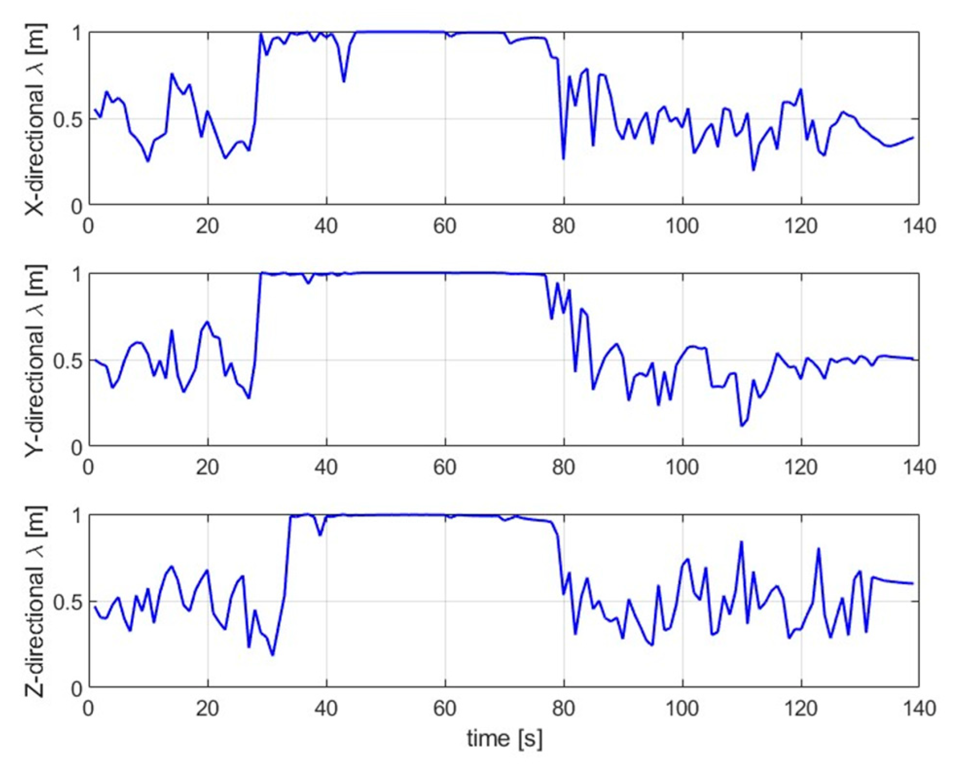
5.3.1. Fission–Fusion in the Absence of Back-Catch

The goal of the UAV swarm control is to achieve self-organized fission–fusion with no anti-catch movement of the sub-swarm and ensure that the parent swarm is not affected by dynamic obstacles. The simulation results are shown in Figure 3a–f. Figure 3a demonstrates the complete UAV swarm, in which the fission sub-swarm process for trapping when dynamic obstacles are encountered and the process of returning to the parent swarm after trapping is completed. In such conditions, the dynamic obstacle tracks the swarm from the position of 20 ,   60 ,   0 . When the dynamic obstacle enters the sensing range of the closest agent, the swarm undergoes a fission motion and splits into a sub-swarm with five as well as a parent swarm with fifteen. The sub-swarm quickly completes position coordination to form a stable swarm state while heading to trap the dynamic obstacle. The self-organized returns to the parent swarm to fuse after the trapping is completed. Figure 3b,c shows the initial state of the UAV swarm, and the UAV swarm moving toward the target point, respectively, where the UAVs achieve self-organization to keep a stable swarm state when no dynamic obstacles are encountered. Figure 3d indicates that when the UAV swarm detects a dynamic obstacle, it starts a fission motion to achieve sub-swarm stabilization quickly, and commences a trapping motion for the dynamic obstacle by flying to a pseudo-target point that is not the same as the real target point simultaneously. Figure 3e shows that when the sub-swarm detects a dynamic obstacle leaving the trapping area and its direction is different from that of the parent swarm, the sub-swarm decides to complete the trapping movement and returns to the parent swarm. Figure 3f shows that after the sub-swarm returns to the parent swarm, the sub-swarm as well as the parent swarm achieve self-organized fusion and reach the target point together.
Figure 4 represents the variation process of polarization and differentiation indices of the UAV swarm in the fission–fusion process in the absence of back-catch. The polarization index in Figure 4a indicates that the UAV swarm achieved the swarm fusion process within 20 s. The polarization index of the sub-swarm Figure 4b and the parent swarm Figure 4c quickly stabilized back to one after the occurrence of the sub-swarm movement. When the sub-swarm returned to the parent swarm, the polarization index re-stabilized around one after a brief drop in a short period. The polarization index of the parent swarm is affected only during the fission process. The whole process is not directly influenced by dynamic obstacles.
Figure 5 represents the variation process of the UAV swarm’s differentiation index in the fission–fusion process without a back-catch. The differentiation index illustrates that the UAV swarm is one swarm around 3~23 s, the sub-swarm is differentiated around 23 s, and the differentiation index of the two swarms is stable at around one. When the sub-swarm returns to the parent swarm after completing trapping for about 76 s, they are fused into a steady swarm, which proves the effectiveness of the bio-inspired self-organized fission–fusion swarm algorithm for UAV swarm with a controllable number of UAVs in sub-swarm.

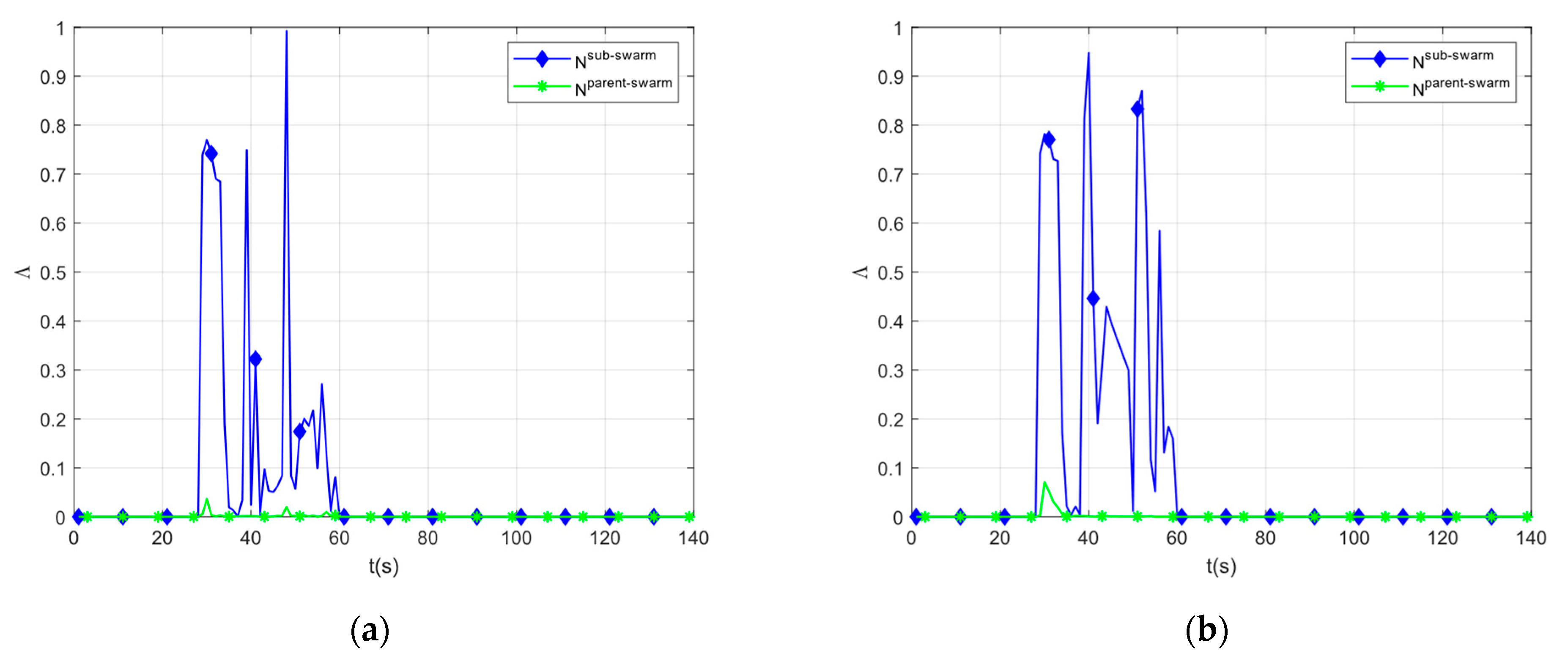
5.3.2. Fission–Fusion Processes in the Case of Back-Catch

In this section, we test whether the UAV swarm can achieve fission–fusion and complete trapping movement to ensure that the parent swarm is not affected by dynamic obstacles when anti-trapping exists.
The simulation results are shown in Figure 6a–f. In Figure 6a, the complete UAV swarm fission into sub-swarm when encountering dynamic obstacles. The sub-swarm completes the trapping motion and finally returns to the parent swarm after completing the trapping in the presence of counter-trapping movement. In such conditions, dynamic obstacles track swarm from the location of 20 ,   60 ,   0 . When a dynamic obstacle enters the sensory range of the closest agent, the swarm self-organizes fission into a sub-swarm with five agents and a parent swarm with fifteen agents. Sub-swarm quickly completes position coordination to form a stable state while heading to trap dynamic obstacles. During the trapping process, the dynamic obstacle are tracked the parent swarm again, and the sub-swarm self-organized the counter-trapping movement and successfully trapped the dynamic obstacle. Finally, the sub-swarm completes the trapping action and self-organizes back to the mother group for integration. Figure 6b shows the initial state of the UAV swarm. In Figure 6c, when the UAV swarm detects a dynamic obstacle, it performs a fission movement and quickly achieves sub-swarm stabilization while starting to trap the dynamic obstacle. Figure 6d indicates that when a dynamic obstacle enters the trapping interval of a sub-swarm, the sub-swarm turns to fly to a pseudo-target point that is different from the actual target point. Figure 6e shows that when the dynamic obstacle has left the trapping area and the flight direction is the same as the parent swarm, the sub-swarm starts a counter-trapping movement and successfully traps the dynamic obstacle again. Figure 6f indicates the sub-swarm returning to the parent swarm after completing the trapping movement to fuse and reach the target point together.
Figure 7 represents the variation process of the UAV swarm’s polarization index in the fission–fusion process in the anti-catch situation. The polarization index demonstrates that the UAV swarm achieves the fusion process from zero to one in 0~10 s. The polarization indices of the sub-swarm and the parent swarm rapidly stabilized back around one after the emergence of the splitting movement, which indicates the formation of two stable swarms. When the sub-swarm returned to the parent swarm, the polarization index re-stabilized around one after a brief decline in a short period. The polarization index of the parent swarm is known to be affected only during the fission process, and the whole process is not directly influenced by dynamic obstacles, which illustrated the effectiveness of the bio-inspired self-organized fission–fusion swarm algorithm for the UAV swarm with a controllable number of UAVs in sub-swarm.
Figure 8 denotes the variation process of the UAV swarm’s differentiation index in the fission–fusion process in the anti-catch situation. The differentiation index shows that the UAV swarm is one swarm from 0 to 30 s, the sub-swarm is differentiated at about 30 s, and the differentiation index of both swarms is stable around one. In the case of anti-capture, the differentiation index did not receive severe effects from the anti-capture process. When the sub-swarm returned to the parent swarm after completing trapping, they fuse into a stable swarm.
Figure 9 represents the precision of response stimuli of sub-swarm and parent swarm during the fission–fusion of the UAV swarm in two cases. The results in Figure 9a show the change in the precision of response stimuli is without backpatch, and the results in Figure 9b show the change in the precision of response stimuli with backpatch. Analyzed in Figure 9, the swarm exhibited good precision of response stimuli performance in the sub-swarm in the fission process. The induced forces and random disturbances of the sub-swarm lead to the significant magnitude of the variation in the precision of response stimuli. For the parent swarm, the fission was slightly affected by dynamic obstacles at the beginning, which is mainly produced by the need for the parent swarm to regroup during the fission process, which is caused by the indirect effect of dynamic obstacles. The dynamic obstacles did not affect the parent swarm for the rest of the time.
Figure 10 demonstrates the change in communication load for the UAV swarm, which utilizes the starling topological interaction structures with different sizes of fixed distance structures. Figure 10a,b shows the communication load variation without back-capture, and the communication load variation with back-capture, respectively. The simulation results show that the UAV swarm in the absence of fission reduces the communication pressure in both cases significantly. The starling topological interaction structure still yields some advantages during fission, which is its dominance in the swarm.

6. Conclusions

With the increasing research on UAV swarms, the control methods for self-organized fission–fusion of UAV swarms have become a growing interest of researchers. However, in the field of dynamic obstacles for tracking functions, the rapidly changed behavior of the dynamic obstacles is still challenging for UAV swarm control. A new Bio-inspired Self-organized Fission–fusion Control (BiSoFC) algorithm for the UAV swarm with a controllable number of UAVs in the sub-swarm is proposed to solve such a problem. Unlike the existing algorithms, our proposed method targets dynamic obstacles with a tracking function by fissioning a controllable number of independent sub-swarms to trap the tracking intruders for movement and return to the parent swarm self-organized to complete the fission–fusion. The objective is that the parent swarm is not affected by dynamic obstacles. We introduced the starling topological interaction structure and proved the structure’s competitiveness by adopting communication load evaluation metrics through simulation results. For the two cases, the simulation experiments of the proposed control algorithm are conducted with numerical simulation with evaluation metrics. Experiments demonstrate the effectiveness and feasibility of the proposed bio-inspired self-organized fission–fusion swarm algorithm for a UAV swarm with a controllable number of UAVs in the sub-swarm. In the future, the game mechanism should be considered in the control method of the swarm and an in-depth study of the effect of some specific parameters on the algorithm should be conducted.

Author Contributions

Conceptualization, X.Z. and Y.W.; methodology, W.D.; software, Y.L.; validation, Z.Z., Y.W. and Z.Z.; formal analysis, X.Z.; investigation, J.X.; resources, X.Z.; data curation, Y.W.; writing—original draft preparation, X.Z.; writing—review and editing, Y.L. and Y.W.; visualization, X.Z.; supervision, Z.Z.; project administration, W.D.; funding acquisition, W.D. All authors have read and agreed to the published version of the manuscript.

Funding

This research was funded by the National Natural Science Foundation of China (Grant NO. U20B2042), Science and Technology Innovation 2030-Key Project of “New Generation Artificial Intelligence” (Grant NO. 2020AAA01082010). Outstanding Research Project of Shen Yuan Honors College, BUAA (Grant NO. 230121701).

Institutional Review Board Statement

Not applicable.

Informed Consent Statement

Not applicable.

Data Availability Statement

Not applicable.

Conflicts of Interest

The authors declare no conflict of interest.

Appendix A

Dynamic Obstacle Movement Model

We set up a dynamic obstacle with a large sensing range and used the drones which are closest to it as the dynamic obstacle tracking targets. The kinematic equations for the dynamic obstacle are formulated as follows:
x ˙ i n v a d e r = v i n v a d e r v ˙ i n v a d e r = u i n v a d e r δ i n v a d e r v i n v a d e r 2 v i n v a d e r
u i n v a d e r = κ i n v a d e r a u t v i n v a d e r v i n v a d e r + κ i n v a d e r x min son _ subgroup x i n v a d e r x min son _ subgroup x i n v a d e r + δ i n v a d e r v i n v a d e r 2 v i n v a d e r
where x i n v a d e r = x i n v a d e r , y i n v a d e r , h i n v a d e r R n is the 3D position coordinates of the dynamic obstacle, v i n v a d e r R n is the velocity vector of the dynamic obstacle, u i n v a d e r R n is the control input of the dynamic obstacle, κ i n v a d e r a u t is the moving inertia coefficient of the dynamic obstacle, κ i n v a d e r is the tracking factor, and δ i n v a d e r v i n v a d e r 2 v i n v a d e r is the friction generated by the dynamic obstacle and the environment.

References

  1. Camazine, S.; Deneubourg, J.L.; Franks, N.R.; Sneyd, J.; Theraula, G.; Bonabeau, E. Self-Organization in Biological Systems; Princeton University Press: Princeton, NJ, USA, 2020. [Google Scholar]
  2. Dutta, K. How birds fly together: The dynamics of flocking. Resonance 2010, 15, 1097–1110. [Google Scholar] [CrossRef]
  3. Sail, P.; Borkar, M.R.; Shaikh, I.; Pal, A. Faunal diversity of an insular crepuscular cave of Goa, India. J. Threat. Taxa 2021, 13, 17630–17638. [Google Scholar] [CrossRef]
  4. Croft, D.P.; James, R.; Thomas, P.O.R.; Hathaway, C.; Mawdsley, D.; Laland, K.N.; Krause, J. Social structure and co-operative interactions in a wild population of guppies (Poecilia reticulata). Behav. Ecol. Sociobiol. 2006, 59, 644–650. [Google Scholar] [CrossRef]
  5. Couzin, I.D.; Laidre, M.E. Fission–fusion populations. Curr. Biol. 2009, 19, R633–R635. [Google Scholar] [CrossRef] [PubMed] [Green Version]
  6. Kummer, H.; Loy, J. Social Behavior and Habitat. (Book Reviews: Primate Societies. Group Techniques of Ecological Adap-tation). Science 1971, 174, 49–51. [Google Scholar] [CrossRef]
  7. Schusterman, R.J.; Thomas, J.A.; Wood, F.G.; Schusterman, R. Dolphin Cognition and Behavior: A Comparative Approach; Psychology Press: London, UK, 2013. [Google Scholar]
  8. Mann, J.; Connor, R.C.; Tyack, P.L.; Whitehead, H. Cetacean Societies: Field Studies of Dolphins and Whales; University of Chicago Press: Chicago, IL, USA, 2000. [Google Scholar]
  9. Pryor, K.; Norris, K.S. Dolphin Societies: Discoveries and Puzzles; University of California Press: Berkeley, CA, USA, 1991. [Google Scholar]
  10. Symington, M.M. fission-fusion social organization in Ateles and Pan. Int. J. Primatol. 1990, 11, 47–61. [Google Scholar] [CrossRef]
  11. Bajec, I.L.; Heppner, F.H. Organized flight in birds. Anim. Behav. 2009, 78, 777–789. [Google Scholar] [CrossRef]
  12. Haque, M.; Rahmani, A.; Egerstedt, M. A hybrid, multi-agent model of foraging bottlenose dolphins. IFAC Proc. Vol. 2009, 42, 262–267. [Google Scholar] [CrossRef] [Green Version]
  13. Bansal, J.C.; Sharma, H.; Jadon, S.S.; Clerc, M. Spider monkey optimization algorithm for numerical optimization. Memetic Comput. 2014, 6, 31–47. [Google Scholar] [CrossRef]
  14. Zelenka, J.; Kasanický, T.; Budinská, I.; Naďo, L.; Kaňuch, P. SkyBat: A Swarm Robotic Model Inspired by Fission-Fusion Be-haviour of Bats. In Proceedings of the International Conference on Robotics in Alpe-Adria Danube Region, Poitiers, France, 29 September 2018; pp. 521–528. [Google Scholar] [CrossRef]
  15. Spears, W.M.; Spears, D.F.; Hamann, J.C.; Heil, R. Distributed, physics-based control of swarms of vehicles. Auton. Robot. 2004, 17, 137–162. [Google Scholar] [CrossRef]
  16. Berlinger, F.; Gauci, M.; Nagpal, R. Implicit coordination for 3D underwater collective behaviors in a fish-inspired robot swarm. Sci. Robot. 2021, 6, eabd8668. [Google Scholar] [CrossRef] [PubMed]
  17. Liang, H.; Fu, Y.; Gao, J. Bio-inspired self-organized cooperative control consensus for crowded UUV swarm based on adaptive dynamic interaction topology. Appl. Intell. 2021, 51, 4664–4681. [Google Scholar] [CrossRef]
  18. Wang, C.; Wu, A.; Hou, Y.; Liang, X.; Xu, L.; Wang, X. Optimal deployment of swarm positions in cooperative interception of multiple UAV swarms. Digit. Commun. Netw. 2022, 8. [Google Scholar] [CrossRef]
  19. Aureli, F.; Schaffner, C.M.; Boesch, C.; Bearder, S.K.; Call, J.; Chapman, C.A.; Connor, R.; Fiore, A.D.; Dunbar, R.I. Fission-fusion dynamics: New research algorithms. Curr. Anthropol. 2008, 49, 627–654. [Google Scholar] [CrossRef]
  20. Magesh, M.; Jawahar, P.K.; Saranya, S.N. Spider Monkey Based Metaheuristic Tuning of PID Controllers for Stability Landing of UAV’S with SMP-Auxetic Landing Gears. In Proceedings of the 2022 First International Conference on Electrical, Information and Communication Technologies (ICEEICT), Trichy, India, 16–18 February 2022; pp. 1–6. [Google Scholar] [CrossRef]
  21. Reynolds, C.W. Flocks, Herds and Schools: A Distributed Behavioral Model. In Proceedings of the 14th Annual Conference on Computer Graphics and Interactive Techniques, Anaheim, CA, USA, 27–31 July 1987; pp. 25–34. [Google Scholar] [CrossRef] [Green Version]
  22. Olfati-Saber, R. Flocking for multi-agent dynamic systems: Algorithms and theory. IEEE Trans. Autom. Control 2006, 51, 401–420. [Google Scholar] [CrossRef] [Green Version]
  23. Lee, G.; Chong, N.Y. A geometric approach to deploying robot swarms. Ann. Math. Artif. Intell. 2008, 52, 257–280. [Google Scholar] [CrossRef]
  24. Lei, X.K.; Liu, M.Y.; Yang, P.P. Fission control algorithm for swarm based on local following interaction. Control Decis. 2013, 28, 741–745. Available online: http://en.cnki.com.cn/Article_en/CJFDTOTAL-KZYC201305020.htm (accessed on 30 August 2022).
  25. Yang, P.; Yan, M.; Song, J.; Tang, Y. Self-Organized fission-fusion Control Algorithm for Flocking Systems Based on Inter-mittent Selective Interaction. Complexity 2019, 2019, 2187812. [Google Scholar] [CrossRef]
  26. You, H.E. Mission-driven autonomous perception and fusion based on UAV swarm. Chin. J.Aeronaut. 2020, 33, 2831–2834. [Google Scholar] [CrossRef]
  27. Ling, H.; Mclvor, G.E.; van der Vaart, K.; Vaughan, R.T.; Thornton, A.; Ouellette, N.T. Costs and benefits of social relationships in the collective motion of bird flocks. Nat. Ecol. Evol. 2019, 3, 943–948. [Google Scholar] [CrossRef]
  28. Ling, H.; Mclvor, G.E.; van der Vaart, K.; Vaughan, R.T.; Thornton, A.; Ouellette, N.T. Local interactions and their group-level consequences in flocking jackdaws. Proc. R. Soc. B 2019, 286, 20190865. [Google Scholar] [CrossRef]
  29. Ballerini, M.; Cabibbo, N.; Candelier, R.; Cavagna, A.; Cisbani, E.; Giardina, I.; Zdravkovic, V. Interaction ruling animal collective behavior depends on topological rather than metric distance: Evidence from a field study. Proc. Natl. Acad. Sci. USA 2008, 105, 1232–1237. [Google Scholar] [CrossRef] [Green Version]
  30. Hildenbrandt, H.; Carere, C.; Hemelrijk, C.K. Self-organized aerial displays of thousands of starlings: A model. Behav. Ecol. 2010, 21, 1349–1359. [Google Scholar] [CrossRef]
  31. Templeton, J.J.; Giraldeau, L.A. Patch assessment in foraging flocks of European starlings: Evidence for the use of public information. Behav. Ecol. 1995, 6, 65–72. [Google Scholar] [CrossRef]
  32. Ourari, R.; Cui, K.; Elshamanhory, A.; Koeppl, H. Nearest-Neighbor-Based Collision Avoidance for Quadrotors via Rein-Forcement Learning. In Proceedings of the International Conference on Robotics and Automation (ICRA), Philadelphia, PA, USA, 23–27 May 2022; pp. 293–300. [Google Scholar] [CrossRef]
  33. Liu, Z.; Tian, Y.; Li, C. Coadaptive following control of swarm robot system with multiple leaders in dynamic damping environment. Jiqiren 2011, 33, 385–393. [Google Scholar] [CrossRef]
  34. Ren, W.; Beard, R.W. Constrained Nonlinear Tracking Control for Small Fixed-Wing Unmanned Air Vehicles. In Proceedings of the 2004 American Control Conference, Boston, MA, USA, 30 June–2 July 2004; pp. 4663–4668. [Google Scholar] [CrossRef]
  35. Couzin, I.D.; Krause, J.; Franks, N.R.; Levin, S.A. Effective leadership and decision-making in animal groups on the move. Nature 2005, 433, 513–516. [Google Scholar] [CrossRef]
  36. Vicsek, T.; Zafeiris, A. Collective motion. Phys. Rep. 2012, 517, 71–140. [Google Scholar] [CrossRef] [Green Version]
  37. Stojakovic, P.; Rasuo, B. Single propeller airplane minimal flight speed based upon the lateral maneuver condition. Aerosp. Sci. Technol. 2016, 49, 239–249. [Google Scholar] [CrossRef]
  38. Stojaković, P.; Velimirović, K.; Rašuo, B. Power optimization of a single propeller airplane take-off run on the basis of lateral maneuver limitations. Aerosp. Sci. Technol. 2018, 72, 553–563. [Google Scholar] [CrossRef]
  39. Vicsek, T.; Czirók, A.; Ben-Jacob, E.; Cohen, I.; Shochet, O. Novel type of phase transition in a system of self-driven particles. Phys. Rev. Lett. 1995, 75, 1226. [Google Scholar] [CrossRef]
Figure 1. The effect of dynamic obstacles on traditional swarm motion. (a) swarm reaches the target point in a roundabout manner avoiding dynamic obstacles; (b) swarm reaches the target point by avoiding dynamic obstacles without tracking capabilities in fission–fusion; (c) swarm avoids dynamic obstacles with tracking capabilities in a roundabout manner but cannot reach the target point; (d) swarm evades dynamic obstacles with tracking capabilities in a fission–fusion but cannot reach the target point.
Aerospace 09 00714 g001
Figure 2. Comparison of fixed-distance interaction structure and topological interaction structure. (a) the fixed-distance interaction structure; (b) the topological interaction structure.
Aerospace 09 00714 g002
Figure 3. Fission–fusion process of the UAV swarm without anti-catch mechanism. (a) the process of the complete UAV swarm fission–fusion; (b) the initial state of the UAV swarm; (c) the swarm quickly forms a stable swarm state; (d) the swarm performs fission movement and traps dynamic obstacles; (e) the subs-warm completes its trapping movement and starts to return to the parent swarm; (f) the sub-swarm fusion with the parent swarm.
Aerospace 09 00714 g003
Figure 4. Polarization index in the fission–fusion process of the UAV swarm without an anti-capture situation. (a) overall polarization index; (b) sub-swarm polarization index; (c) parent swarm polarization index.
Aerospace 09 00714 g004
Figure 5. Divergence indices in the fission–fusion process of the UAV swarm without anti-catch situation.
Aerospace 09 00714 g005
Figure 6. Fission–fusion process of UAV swarm under the anti-capture situation. (a) the process of the complete UAV swarm fission–fusion; (b) the initial state of the UAV swarm; (c) the swarm quickly forms a stable swarm state; (d) the swarm performs fission movement and traps dynamic obstacles; (e) sub-swarm to dynamic obstacles for re-capture movement; (f) the sub-swarm completes trapping and returns to the mother swarm for fusion.
Aerospace 09 00714 g006aAerospace 09 00714 g006b
Figure 7. Polarization indices in the fission–fusion process of UAV swarm under the anti-catch situation. (a) overall polarization index; (b) sub-swarm polarization index; (c) parent swarm polarization index.
Aerospace 09 00714 g007
Figure 8. Divergence indices in the fission–fusion process of UAV swarm under the anti-catch situation.
Aerospace 09 00714 g008
Figure 9. Precision of response stimuli of sub-swarm and parent swarm in two cases. (a) the precision of response stimuli without backpatch; (b) the precision of response stimuli with backpatch.
Aerospace 09 00714 g009
Figure 10. Variation of communication load under different interaction structures in two cases. (a) the communication load variation without back-capture; (b) the communication load variation with back-capture.
Aerospace 09 00714 g010
Table 1. Swarm simulation parameter setting.
ParametersDescriptionNumerical Value
γ i n e inertia coefficient0.8
ξ environmental damping factor0.004
ϑ random noise factor0.003
Γ p o s position cooperation factor 1
Γ v e l s velocity alignment factor1
l c g decay coefficient0.2
l a g desired spacing0.2
α ψ self-driving instrument control parameters.0.75
α v 3
α h 0.3
α h ˙ 1
v min minimum horizontal speed0.05
v max maximum horizontal speed1.5
φ max maximum lateral overload10
max maximum height change rate2.35
ɡgravitational acceleration9.8
min minimum height change rate−2.35
R R a d i u s perception radius70
ϕ f l o c k polarization index threshold0.85
T testing _ thresholds
ʑ i n d u c t i o n _ a r e a
judgment thresholds
safe trapping range
3
3–5
Publisher’s Note: MDPI stays neutral with regard to jurisdictional claims in published maps and institutional affiliations.

