
LOVE-Bug Deployment Demonstrator

Scoutek Ltd., Firby Lodge, Firby, Bedale DL8 2PW, UK
Aerospace 2022, 9(10), 573; https://doi.org/10.3390/aerospace9100573
Submission received: 2 July 2022
/
Revised: 2 September 2022
/
Accepted: 26 September 2022
/
Published: 1 October 2022
(This article belongs to the Special Issue The Search for Signs of Life on Venus: Science Objectives and Mission Designs)
Abstract
:Life on Venus Expedition (LOVE) Bugs are a proposed family of miniature, featherlight probes for exploring and sensing the Venusian atmosphere. The Bugs carry tiny ThumbSat femtosatellite buses and instruments beneath balloons or flexible parawings. They are designed to descend from 68 to 45 km altitude over several hours because this part of the atmosphere appears to be most welcoming to life as we know it, according to the Venus Life Finder Mission Study. The parawing option is the subject of this work. In order to fit in with larger probe missions, the LOVE-Bug concept is opportunistic. One anticipated opportunity is to be ejected when a “mother probe” needs to deploy a drogue chute for stabilisation through the transonic regime. This work developed an analogy for such a dramatic Venusian ejection by dropping from a high-altitude balloon in Earth’s stratosphere. By packaging the payload in a small-diameter low-drag capsule and dropping from 28 km, the vehicle accelerates to supersonic velocity at around 18 km, where the wing is ejected and deployed. A variant of the NASA ParaWing was created by incorporating a drag tail to help to stabilise the wing at extremely high and low velocities. Design, simulation, building, and testing work was carried out, and two flights were flown. The second flight demonstrated successful deployment of the wing in representative Venusian entry conditions. Both flights demonstrated that the ThumbSat performed as required in “space”-type conditions. Recommendations for future work, to qualify the LOVE-Bugs for operation on Venus, are presented.
1. Introduction
Life on Venus Expedition (LOVE) Bugs are a proposed family of small, featherlight “Bugs”—instrumented buses carried beneath balloons or flexible parawings—for exploring and sensing the Venusian atmosphere. The parawing option is the subject of this work.
The LOVE (currently proprietary) and Bugs concepts were created by the author based on requirements provided by the Venus Life Finder (VLF) Mission team [1].
Parawing + Scientific payload + ThumbSat = LOVE-Bug
The envisaged Bugs are tough enough to survive ejection from a mother probe descending at Mach 1.4 in the Venusian atmosphere to take advantage of natural opportunities to “jump off” at the right place and time. The most likely opportunity would be when the mother probe deploys a drogue chute for deceleration through Mach 1.0. The density of the Venusian atmosphere allows LOVE-Bugs to glide for several hours from 68 to 45 km altitude, the region of the atmosphere that is most welcoming to life as we know it [1].
At the heart of each Bug is a tiny ThumbSat [2] femtosatellite brain, no larger than a human thumb, with an area 49 × 49 mm and mass 25 g for the basic model. As ThumbSat contains all of the usual functions of a larger spacecraft “bus”, a ThumbSat-based planetary probe can be scaled up without significantly increasing the overall probe mass, giving a higher payload mass fraction as the total probe mass increases.
The baseline LOVE-Bug probe concept has a mass of 60 g and volume of 50 × 50 × 35 mm (stowed), so several can be opportunistically squeezed into a small parent probe, giving redundancy and better statistical sampling of the atmosphere. Alternatively, many hundreds can be deployed in a dedicated mission, to provide massive coverage of the planetary atmosphere.
One advantage of the size and nature of LOVE-Bugs is that most of the key performance can be evaluated at full scale on Earth by dropping from high-altitude balloons (HABs) that are small enough (<1 kg) to enable simple handling and logistics—the team involved has conducted many such HAB flights. The concept is not especially complex, so practical tests are preferred for proof-of-concept testing, rather than relying on simulation. Empirical testing could be carried out in a wind tunnel, but there are few facilities in the world that provide supersonic flow and are large enough to accommodate a wing of the proposed scale. Additionally, such facilities are expensive to operate, and it is challenging to arrange the test to fully simulate parachute deployment.
The purpose of this work is to practically demonstrate the deployment of the proposed parawing in conditions similar to a Venusian delivery, by an analogue in the Earth’s upper atmosphere. As the proposed LOVE-Bugs for the final flight missions may vary in mass from 60 g to 1 kg or more (for the whole vehicle), the most practical and safe test of the behaviour of such a wide range of vehicles is to deploy a median mass payload of ~0.5 kg and drop it from such an altitude that it is travelling at supersonic velocity by the time it descends to 18 km (the equivalent of Venusian ~68 km altitude) [3].
The secondary goal of this work is to track ThumbSat’s telemetry signal at distributed ground stations to assess transmission range and performance.
Summary of challenges and goals:
- Test the deployment of the wing system proposed for Venusian payload delivery, assuming that similarity between the high-altitude Earth analog and Venusian upper atmosphere is achieved by similar:
- o
- Payload mass and wing dimensions, i.e., similar characteristic aerodynamic dimensions.
- o
- Atmospheric density.
- o
- Deployment Mach number (≥Mach 1.0).
- Test that the ThumbSat including battery continue to operate in conditions similar to parts of the proposed Venusian mission, particularly:
- o
- Temperature −55 °C to +30 °C, <10 mbar to 1 atmosphere.
Although not a primary goal, the mission would also be used to gain experience using devices such as cameras and trackers that can support future test flights, and also to assess the ThumbSat’s performance, such as downlink transmission range.
2. Concept
The key requirement is to deploy a parawing at >Mach 1.0 at an altitude of 18 km (equivalent to ~68 km altitude on Venus), using a ThumbSat to control deployment. To do this safely, while keeping the vehicle lightweight and not using propulsion, or requiring an unfeasibly large balloon to carry it to extreme altitudes, a slender dense aerodynamic “capsule” with a high ballistic coefficient (high mass to drag ratio) was selected, which could be dropped to accelerate to the required velocity.
Other requirements:
- All parts of the payload should be recoverable for future flights.
- The wing deployment and subsequent flight should be recorded in high definition video, and a backup tracker should be incorporated for recovery.
- The ThumbSat transmissions should be monitored by multiple ground stations.
3. Drop Altitude and Velocity Estimation
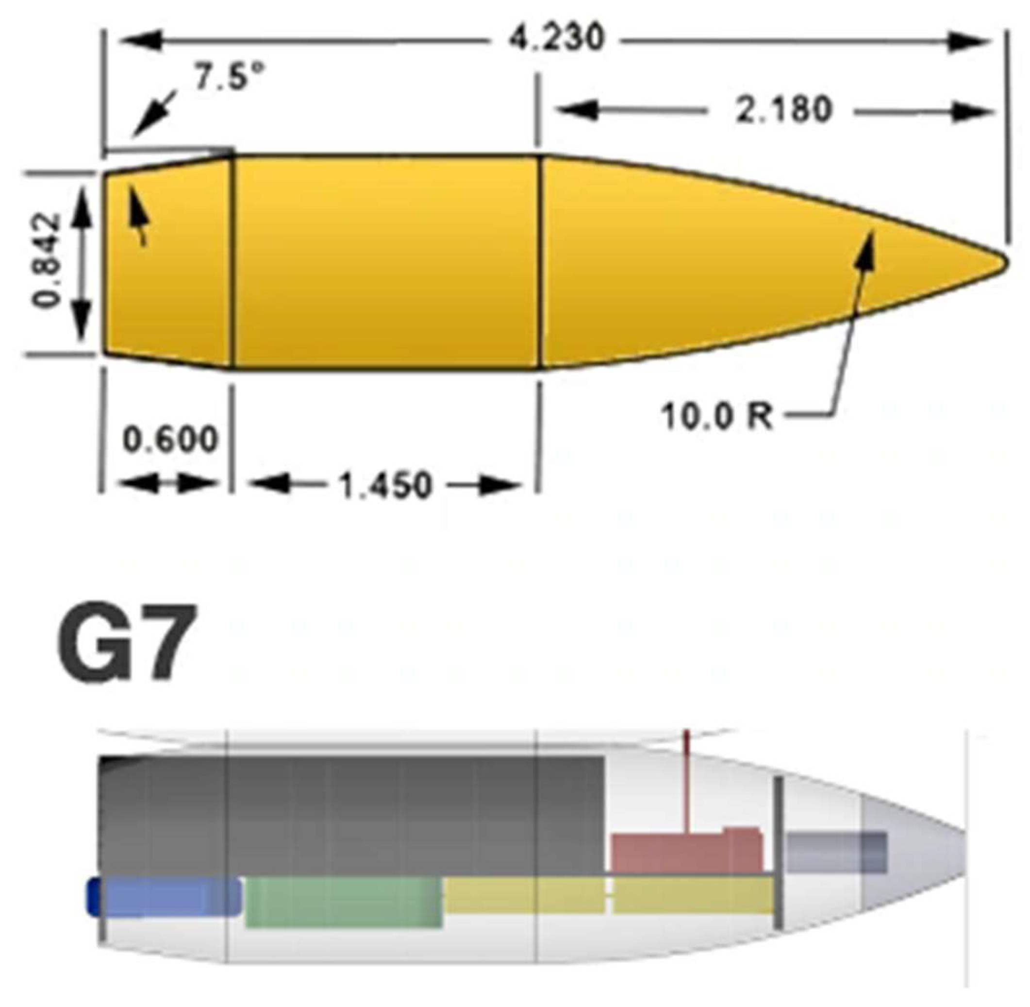
To maximise the reliability of results, the capsule shape was based on a known low-drag shape, that of the G7 bullet (Figure 2) [4].
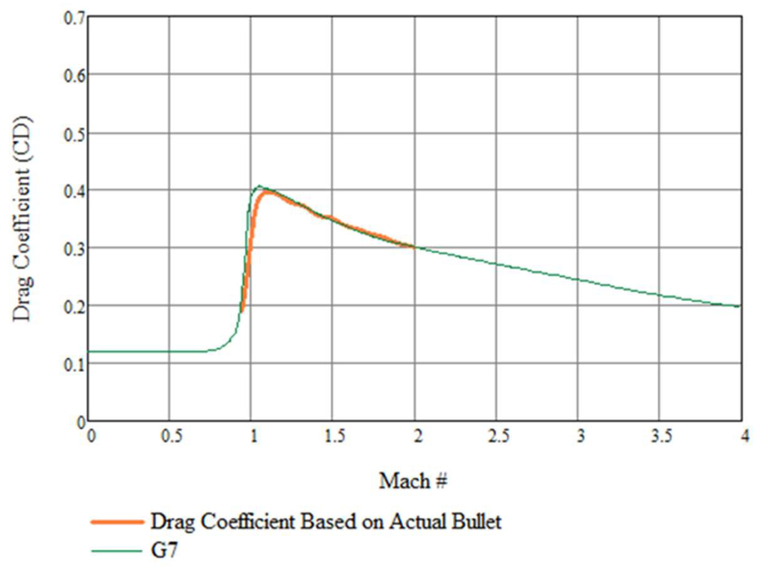
Documented experimental data for the drag coefficient of this shape were used and compared with our own calculations and simulations (Figure 3).
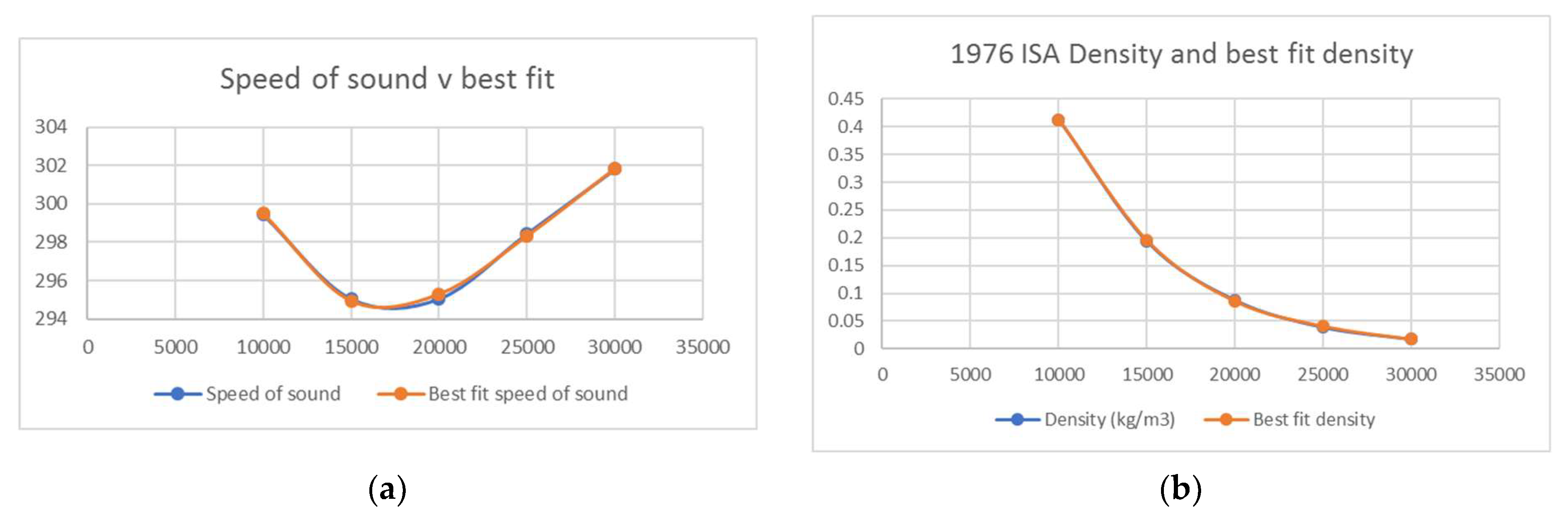
Best fit equations for the speed of sound and density at altitude were created (Figure 4) and added to a master spreadsheet (see Supplementary Material) [5].
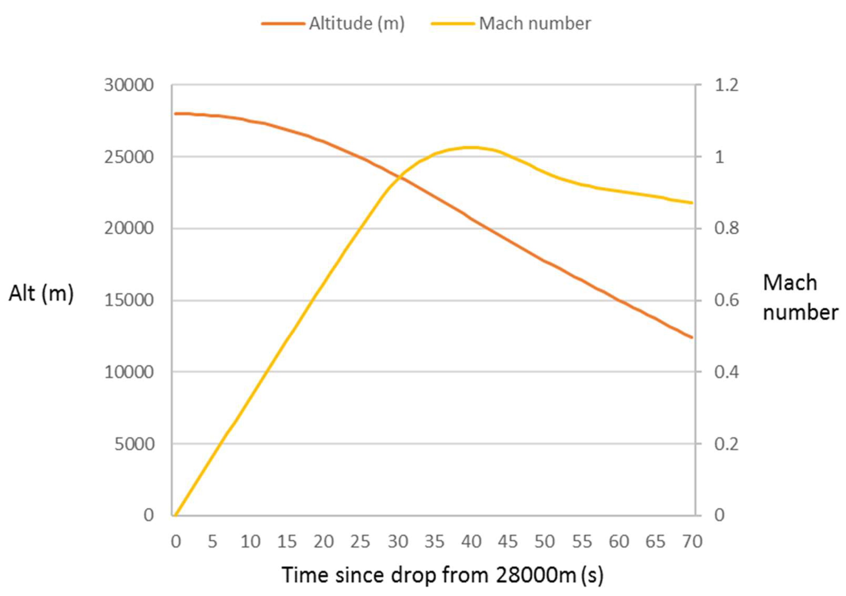
An iterative process was then used to determine a suitable capsule diameter (68 mm), mass (506 g) and drop altitude (28 km) to achieve a representative Venusian planetary entry and deployment. The resulting descent profile is presented in Figure 5. There is a portion of the descent after ~38 s where the velocity is predicted to exceed Mach 1.0 in the low-density upper atmosphere from ~22–19 km. After a few seconds, the atmospheric density increases and the probe decelerates.
4. Payload
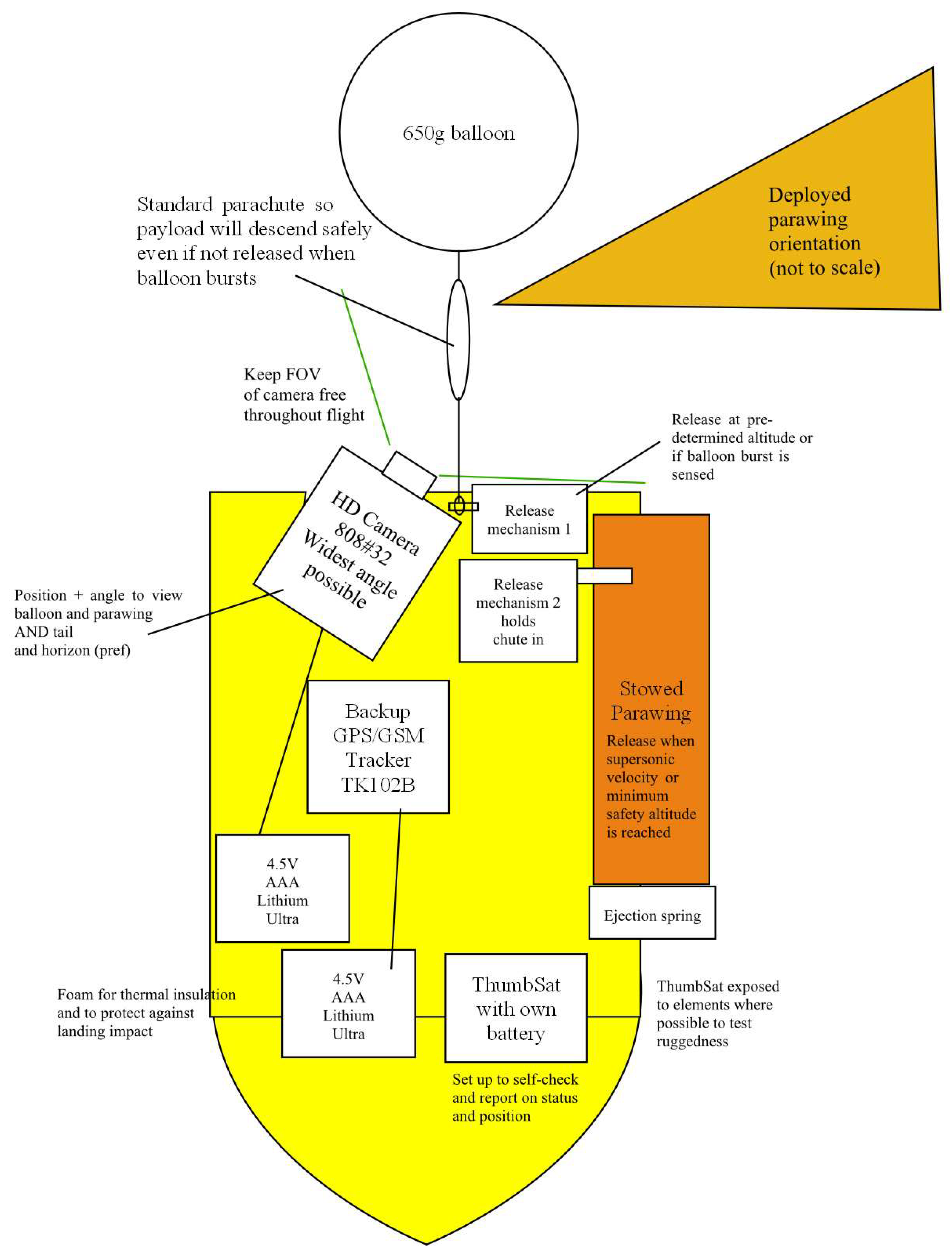
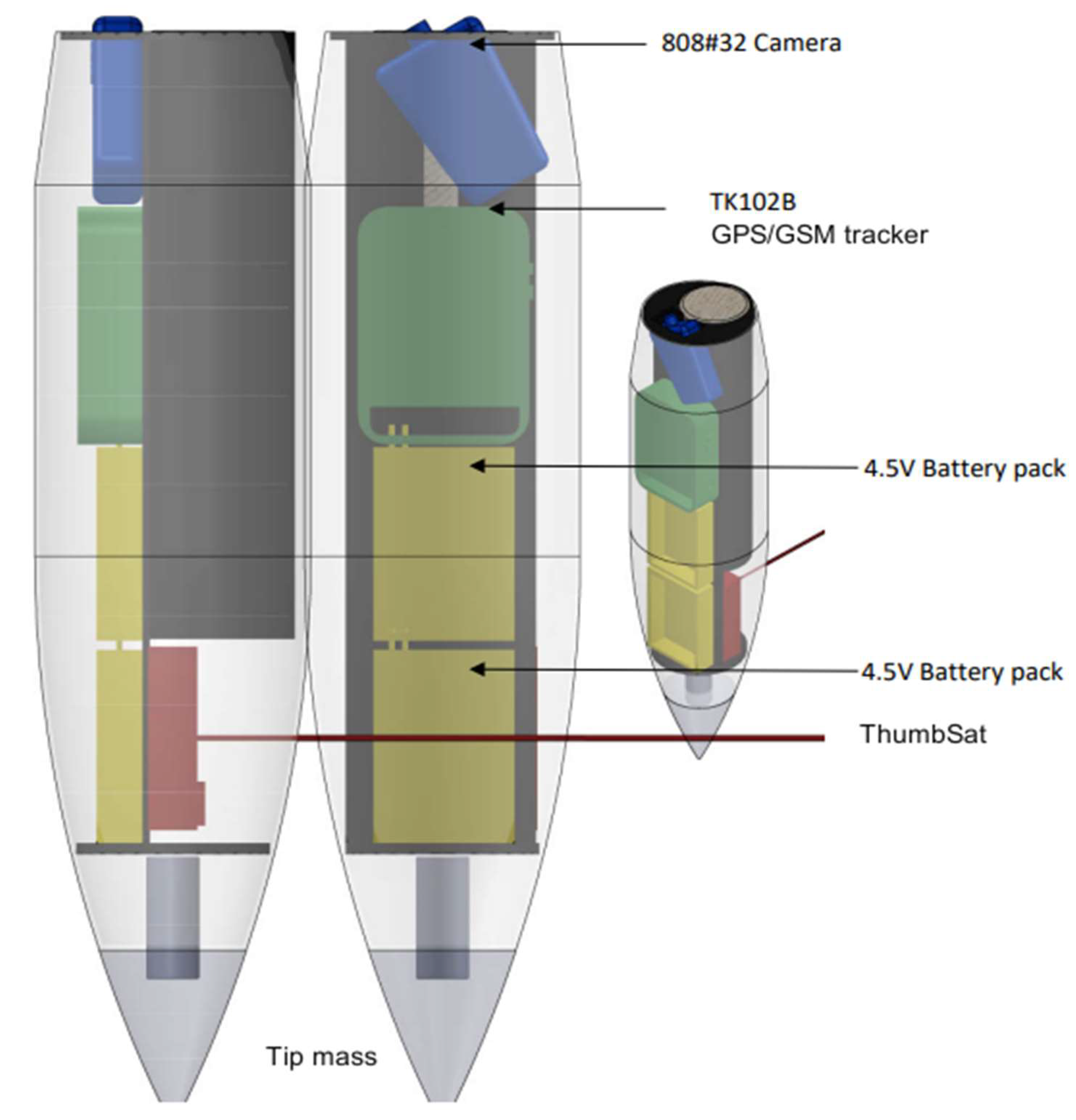
The payload schematic is presented in Figure 6.
The list of components of the payload under test is presented in Table 1.
4.1. ThumbSat
The ThumbSat used in these tests is the V8 version (Figure 7), as proposed for Venus missions [1]. It incorporates all of the usual functions of a much larger satellite “bus”, even though it is only 49 × 49 mm in size and 25 g mass for the basic version. It includes a SkyTraq Venus838 space flight-qualified GPS module for Low Earth Orbit (LEO) use. This is not usable or required for missions beyond Earth but is useful for Earth-based demonstrator missions.
The ThumbSat is powered by a space-flight-type 17355 GE LiSoCl2 high-current battery that has been custom-built for ThumbSat. This 3.6 V, 1800 mAh, battery technology and packaging was selected after a rigorous in-house programme of environmental tests over a wide range of temperatures (−70 to +120 °C), pressures (0 to 2 bar) and vibration levels. The battery has the highest energy density in this class and is spiral wound to give high current discharge. It has a long shelf life.
ThumbSat Flight Algorithm
The ThumbSat was programmed and tested with the following algorithm:
- Transmit position data (baud rate 600 bps) every 15 s during the ascent up to an altitude of 15 km, then every 10 s afterwards.
- Transmit one byte to indicate whether output_1 and output_2 were activated.
- If altitude > 28 km or balloon is sensed to be dropping, trigger output_1 (3 V pulse for 5 s). ThumbSat is assumed to be dropping if (actual position—last position) is <−80 m or if the velocity (from altitude change/time) > 70 m/s.
- Trigger output_2 (3 V pulse for 5 s) *once output_1 has been triggered* IF altitude < 19,000 m OR velocity > 300 m/s, OR time > 50 s after output_1 triggered, if nothing else has happened.
Before flight, the Thumbsat was tested with a GPS simulator at Spirent in Devon, UK to ensure that the onboard GPS continued to function at the simulated altitude and velocity profile that was anticipated during the flight (altitude is above the “COCOM” limit of 18 km). The assembly was placed inside an RF-shielded anechoic chamber. The simulated GPS signals that it would expect to receive if it were travelling at these velocities and altitudes were fed into the chamber, so the GPS receiver and ThumbSat computer behaved as if the ThumbSat was being carried on this trajectory.
4.2. Wing
When considering the potential for life on Venus, the Venus Life Finder team requirements suggested that the most effective probe would be one that is designed to slowly descend through the atmosphere from 68 down to 45 km altitude over 1–3 h, taking measurements, before descending to the surface [1]. Surviving the descent to the surface is desirable but not a requirement.
As opportunities for Venus missions are rare, the team investigated concepts that would require a low overhead of mass, volume, mechanisms, power and logistics from the parent spacecraft and probe, and began by looking at potential deployment opportunities that are common to planetary probes.
Aeroshells for atmospheric planetary probe missions are often shaped and sized such that they require stabilisation through the transonic regime and hence require a drogue chute to be deployed, typically at ~Mach 1.4 [6]. A mortar is usually used to eject the drogue chute away from the supersonic wake turbulence, and this appears to be a good time to deploy smaller tiny opportunistic probes.
No definitive “mother” probe information was available when the team began this programme of work, so a probe with the following properties was assumed, based on the limited available information:
- Mass 37 kg
- 0.3 m diameter
- “Stardust” shape [6]
- Drag coefficient, Cd of 1.5 (varies with conditions)
- Atmospheric entry at 11,500 m/s, entry angle −15 degrees
This gave an estimated ballistic coefficient of 349, peak deceleration of ~160 g at 77 km, and Mach 1.4 at an altitude of 69 km, which is ideal for LOVE-Bug deployment at high altitude as this is where the Venusian atmosphere becomes a potentially habitable zone.
Three options were considered that would allow micro-probes to dwell in the altitude range of 68–45 km: miniature balloons, parachutes and lifting parachutes—“parawings”. The science payload mass fraction was a primary design driver, and after some iterations of the concept, the lifting parawing with the ThumbSat “bus” and experiment payload suspended beneath was found to give the highest mass fraction. An additional scientific benefit of a wing is that unlike a balloon or ballistic parachute, it has a forward velocity component, allowing samples to be collected at the front of the vehicle along a relatively long strip of atmosphere.
The parawing concept was developed by Francis Rogallo and his wife Gertrude, with the aim of allowing anyone to fly freely. The design has continued to evolve since the 1940s, with significant advances being made in the 1960s to produce the NASA Para Wing (NPW) [7]. The wing for the mission described here is inspired by the NPW, specifically the NPW21 (Figure 8).
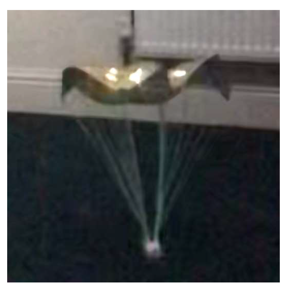
To prepare for the proposal for this work, the project team demonstrated the behaviour of small-scale prototype parawings based on the NPW21 design variant (Figure 9). The design was found to be relatively simple and lightweight, and have good performance in gusting conditions.
A new variant of the NPW was developed by this project team, because this type of wing, especially at a small scale, is susceptible to spinning/tumbling without any self-induced recovery means, particularly when rapidly deployed at 100× its natural gliding speed. Therefore, what is effectively a pair of “chutes” (main wing and drag chute or streamer) with a forward centre of gravity has been designed, which extends the allowable centre of gravity location along the wing chord. This creates a stable design that should naturally adopt a gliding attitude whether from supersonic deployment or release at zero velocity. There is a small cost in drag, but the theoretical benefits in stability outweigh this.
The drag chute or streamer is located and attached in such a way that the glider increases speed in a chute-dive, then once there is enough wind force, the flex-wing becomes effective and gliding begins. Constructing the wing from a quasi-rigid material such as Kapton rather than fully flexible fabric is expected to increase the effectiveness of this flying system.
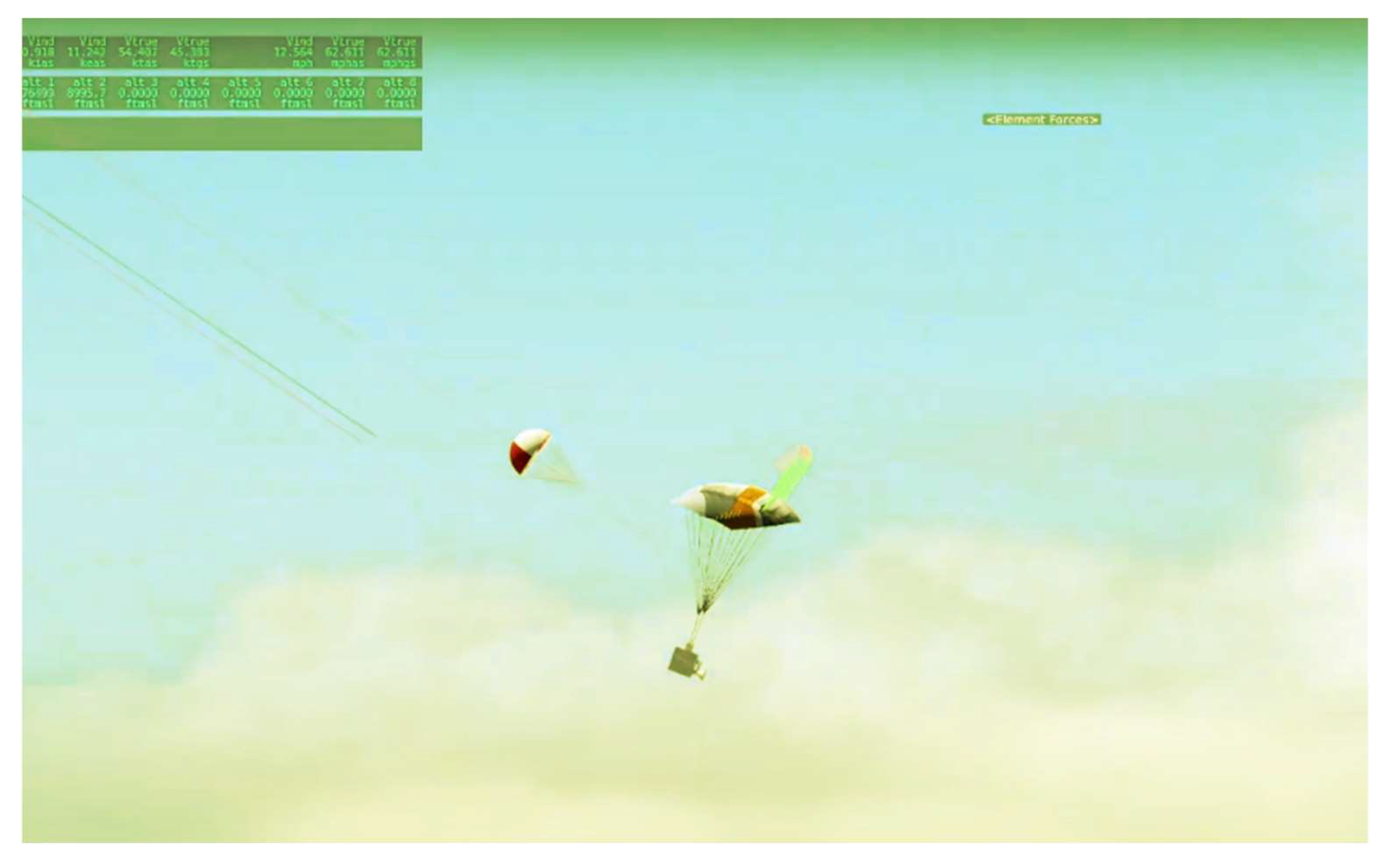
The flight simulation is fully modelled using X-Plane 10 [8] (Figure 10) excluding the true flexible nature of the wing. The simulation was used to investigate the behaviour of the wing plus drag device, and the optimal location for the drag device. This wing is stable over a wide angle-of-attack range and is a simple single-skin, dual-keel construction. It has a lift-drag ratio of approximately 3, and an effective parachute drag as high as 6. Therefore, a wing size as small as a 40 cm span (for a 50 g payload) is enough to reduce the descent rate to 3 ms−1 at 68 km altitude and 1 ms−1 at 45 km. This will typically give a 1–3 h descent time between these altitudes, with forward flight speeds between 3 and 12 ms−1.
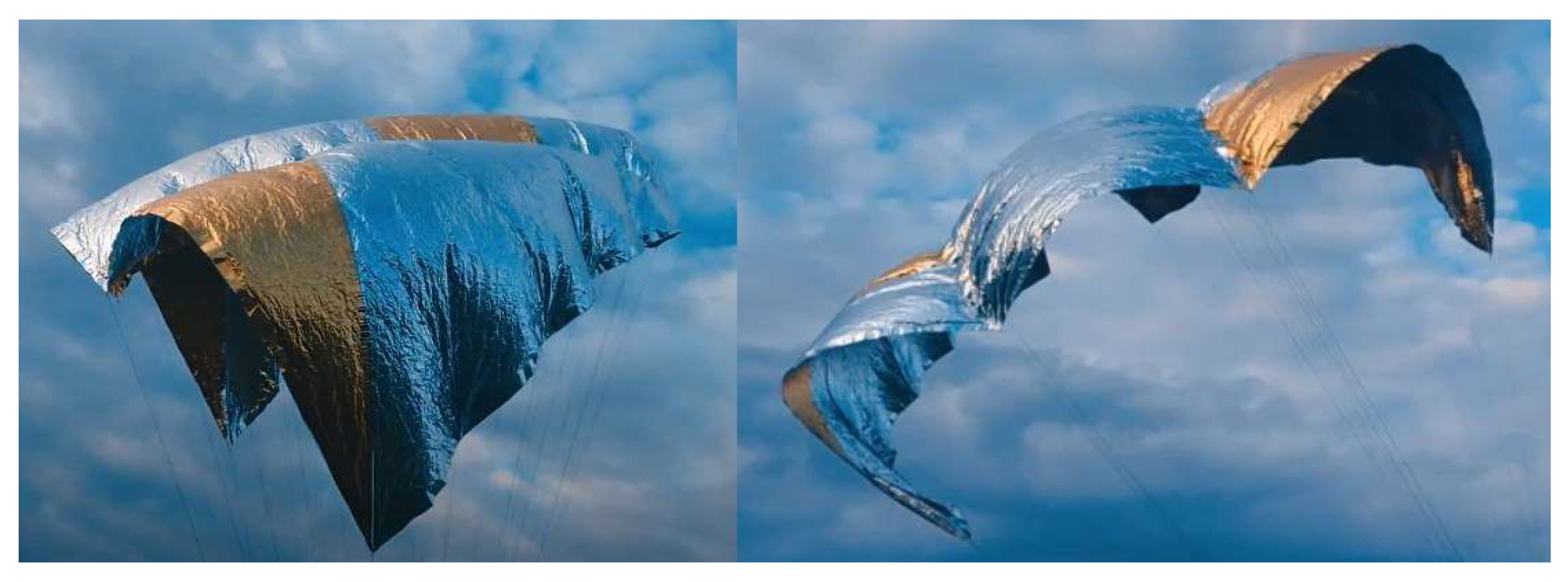
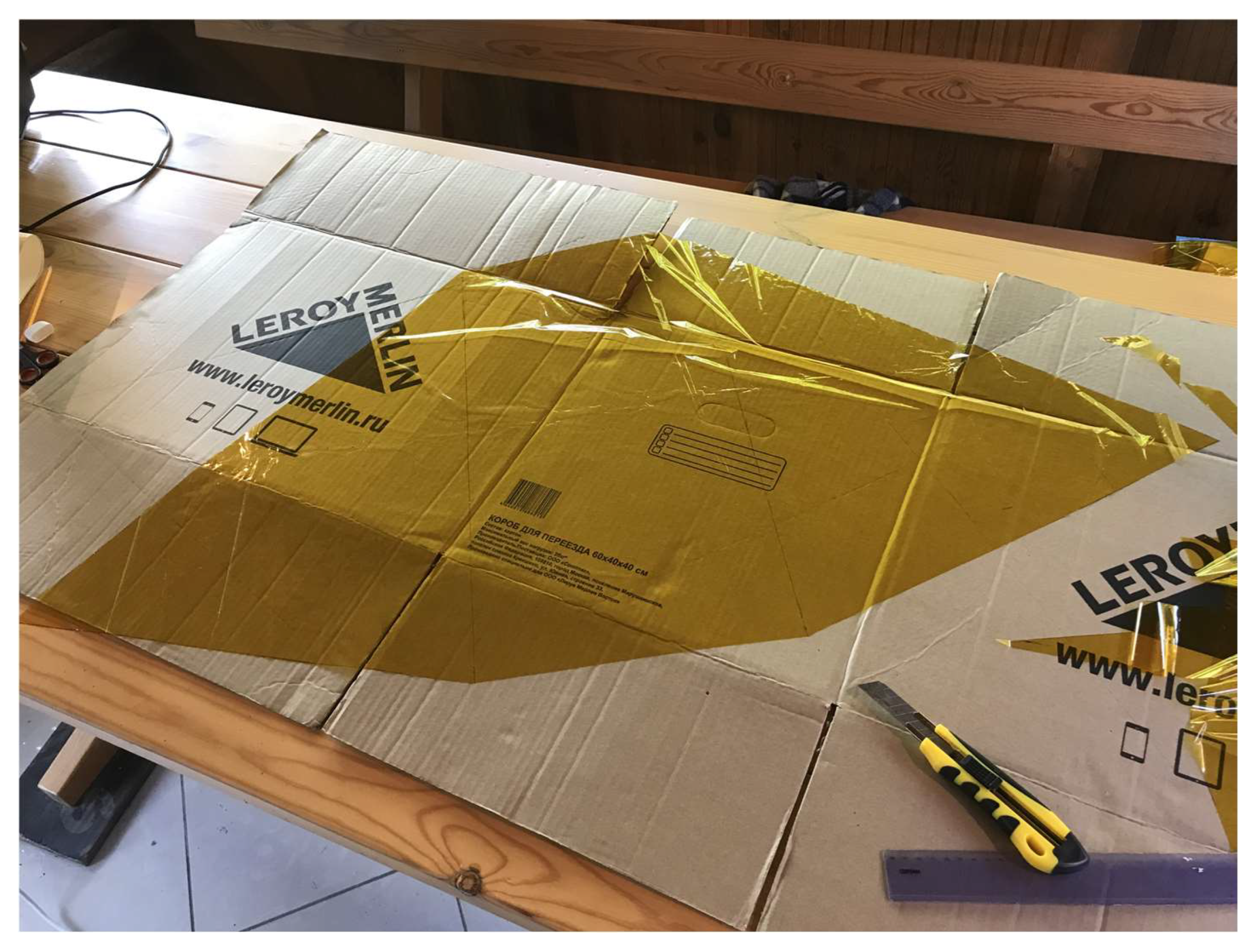
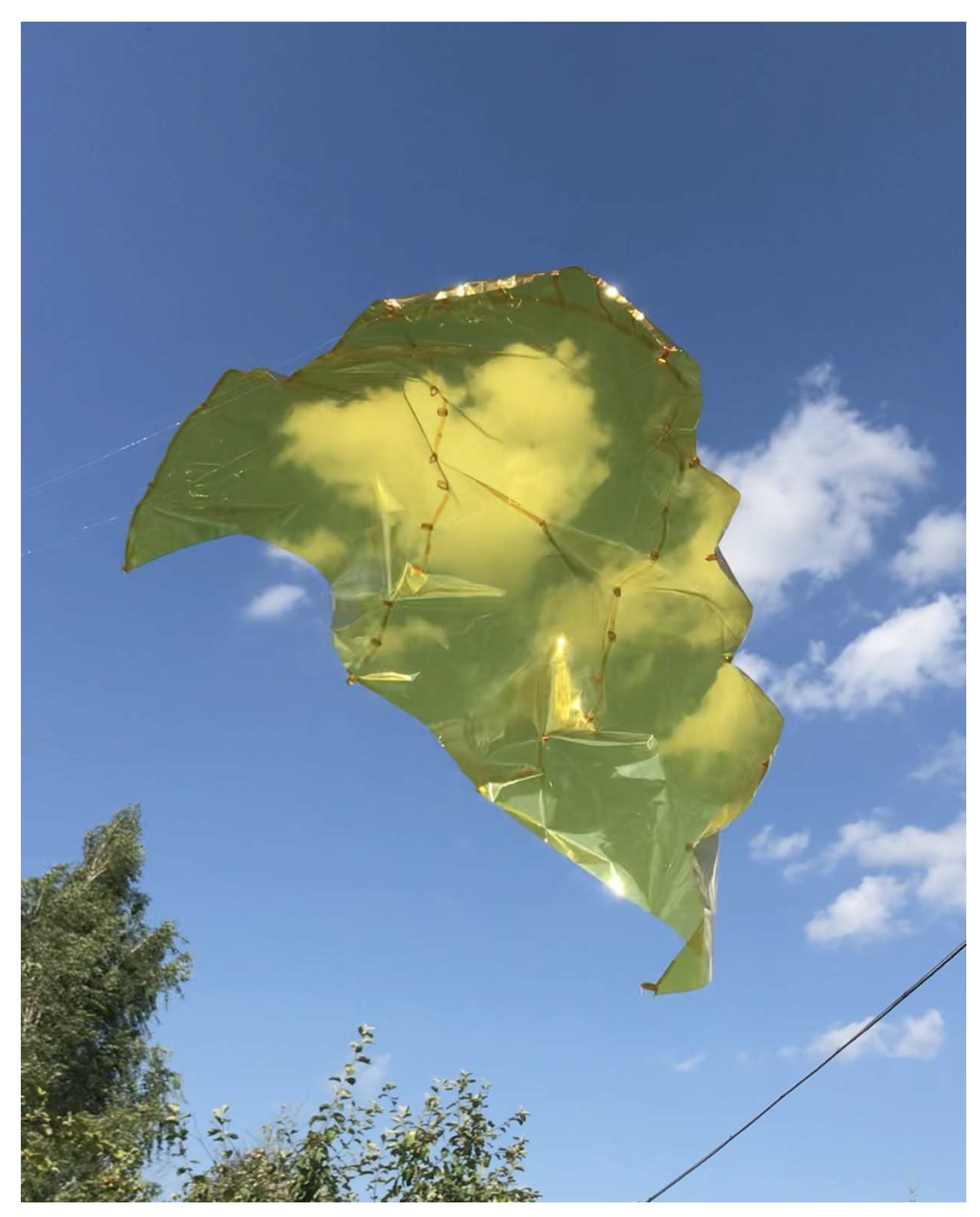
Careful consideration of materials is required for Venus, as the atmosphere contains concentrated sulphuric acid clouds. For the LOVE-Bugs flight version, a 12.5 μm thick Kapton wing with Kapton suspension lines was selected, because Kapton is known to have excellent resistance to sulphuric acid. While not a specific requirement for this work package, the team obtained a roll of Kapton similar to that proposed for Venus and experimented with the wing design, manufacturing techniques (Figure 11) and test flights by flying it as a kite (Figure 12).
For the drop test, a commercial ripstop nylon wing was selected and modified. The wing was scaled for the ~0.5 kg payload, to give a similar ballistic coefficient to the wing designed for Venus. Wingspan is 1.2 m and the wing area is ~0.7 m2.
An extensive test programme was carried out at low altitude, by flying the wing as a kite and by dropping it with a representative payload from heights of 5–10 m in a variety of wind conditions, from still to turbulent. The harness lines were adjusted to alter the angle of attack of the wing by moving the centre of gravity of the payload. The location, width and length of the streamer were also adjusted. These parameters were varied until the wing was judged to give the best glide performance and the drag chute/tail appeared to provide stability at both zero and in gusting wind. Full details of this testing, and the selected geometry, are currently proprietary.
As well as the low-speed low altitude tests, the wing was deployed from a vehicle moving on the ground at 70 mph, so that the aerodynamic pressure and hence forces were similar to those expected during supersonic deployment at high altitude, low density and high velocity.
No attempt was made to incorporate a reefing mechanism, or to provide a pyrotechnic mortar type arrangement to eject the wing beyond the supersonic wake—although this may be beneficial in future. For the demonstrator, the wing is deployed via a spring with a maximum preload of 70 N.
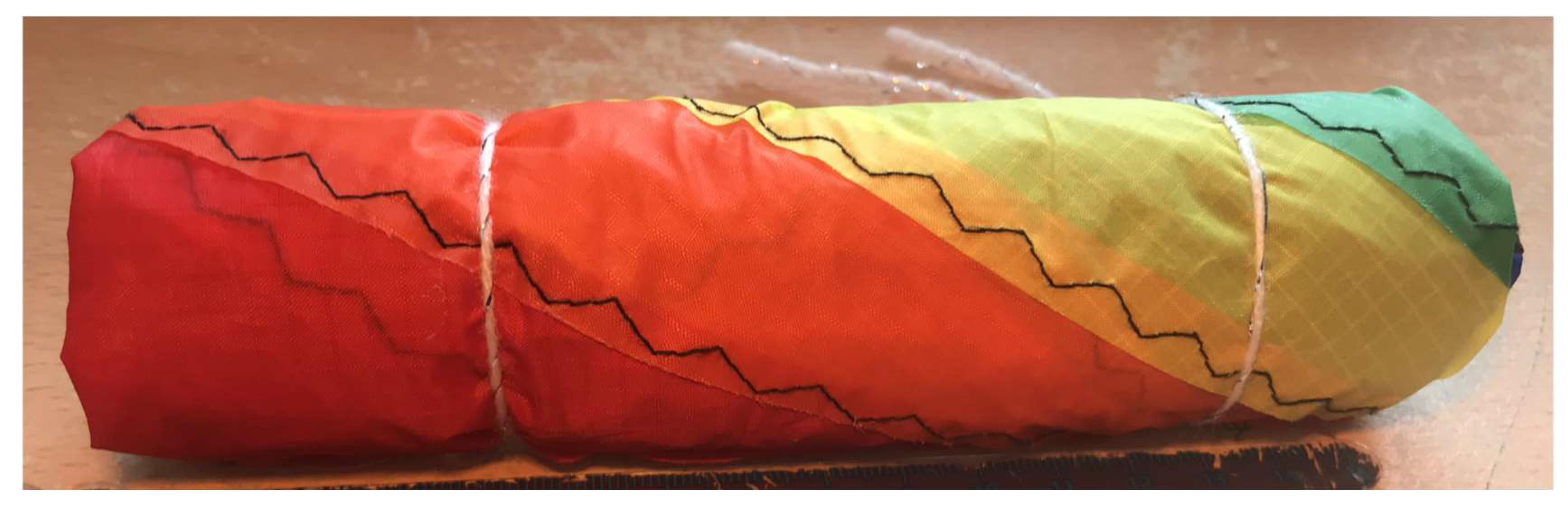
The rip-stop nylon wing wraps up into a larger volume (Figure 13) than the planned thin Venus Kapton wing, but deployment is similar. Once the main wing is stowed, the tail or drag chute is wrapped loosely around it, to provide some drag to help to deploy the wing.
4.3. Camera System
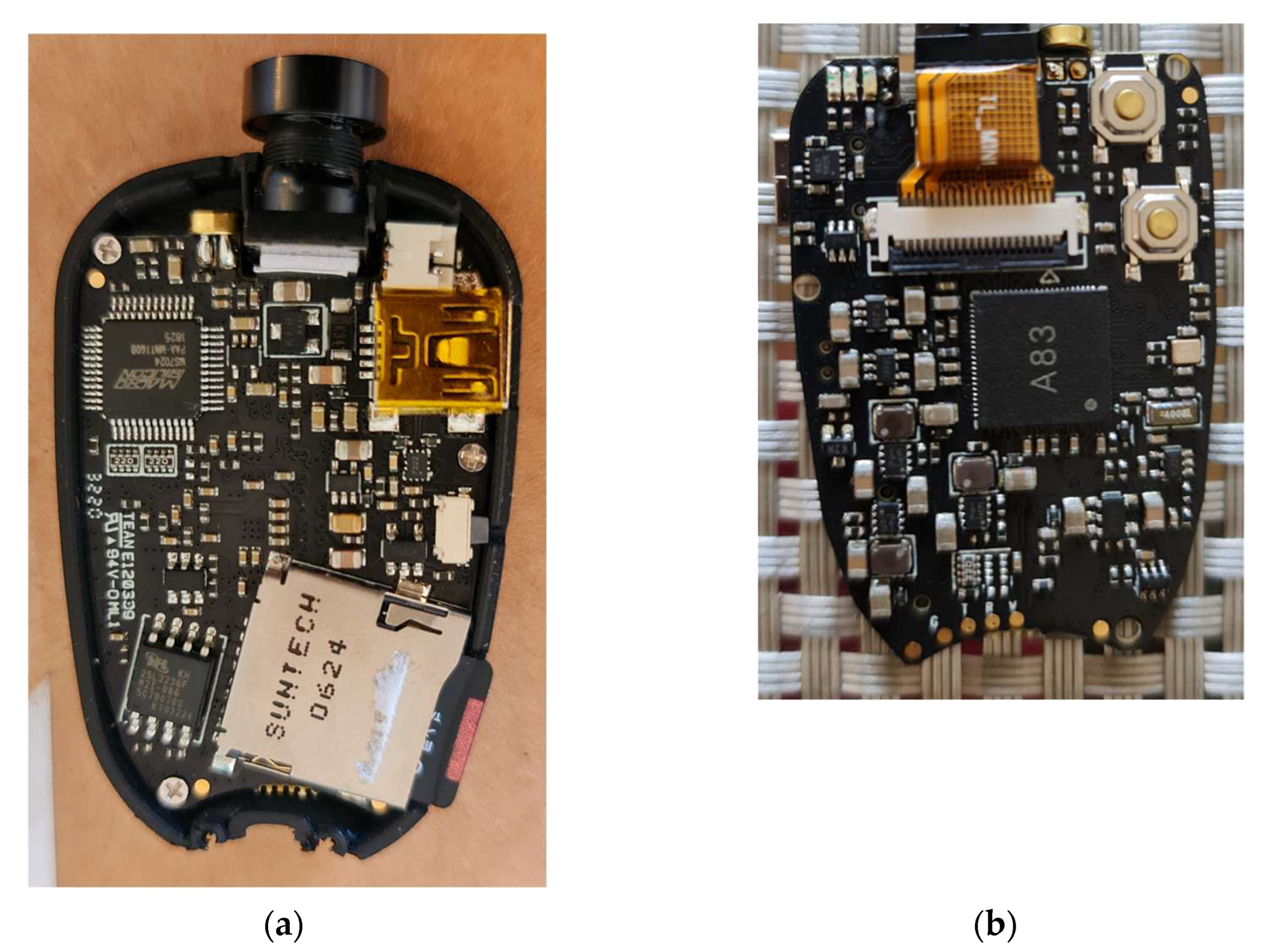
ThumbSat has its own High Definition (HD) camera, but the system around it has been optimised to capture a small number of HD images rather than long-duration HD video. For this work, video is particularly important for monitoring the balloon stability and parawing deployment, so a miniature video camera was required that gives good video quality, has a wide-angle lens, is light-weight, small and operates at low power. The 808#32 camera (Figure 14) was selected. It has a 120° field-of-view lens and has been successfully used on a number of the team’s stratospheric balloon flights. The camera stores data onboard, in a 32 to 64 GB microSD card.
The camera is powered by a COTS 4.5 V battery pack consisting of 3 × 1.5 V AAA Energizer Lithium Ultra batteries. These batteries provide high energy density, perform well at low temperatures and have a long storage life, and have been thoroughly flight-qualified on the team’s previous HAB missions.
4.4. GPS/GSM Tracker System
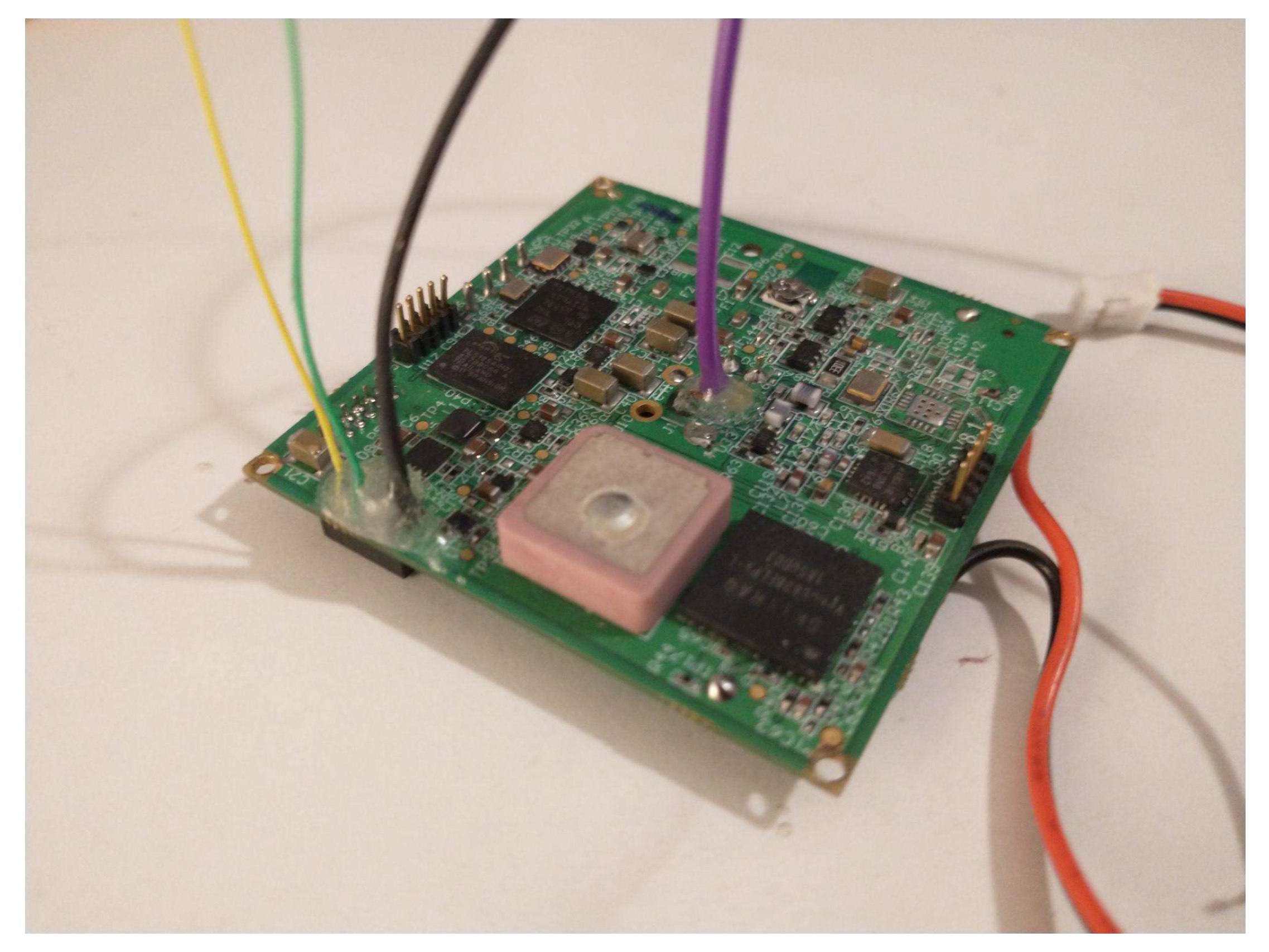
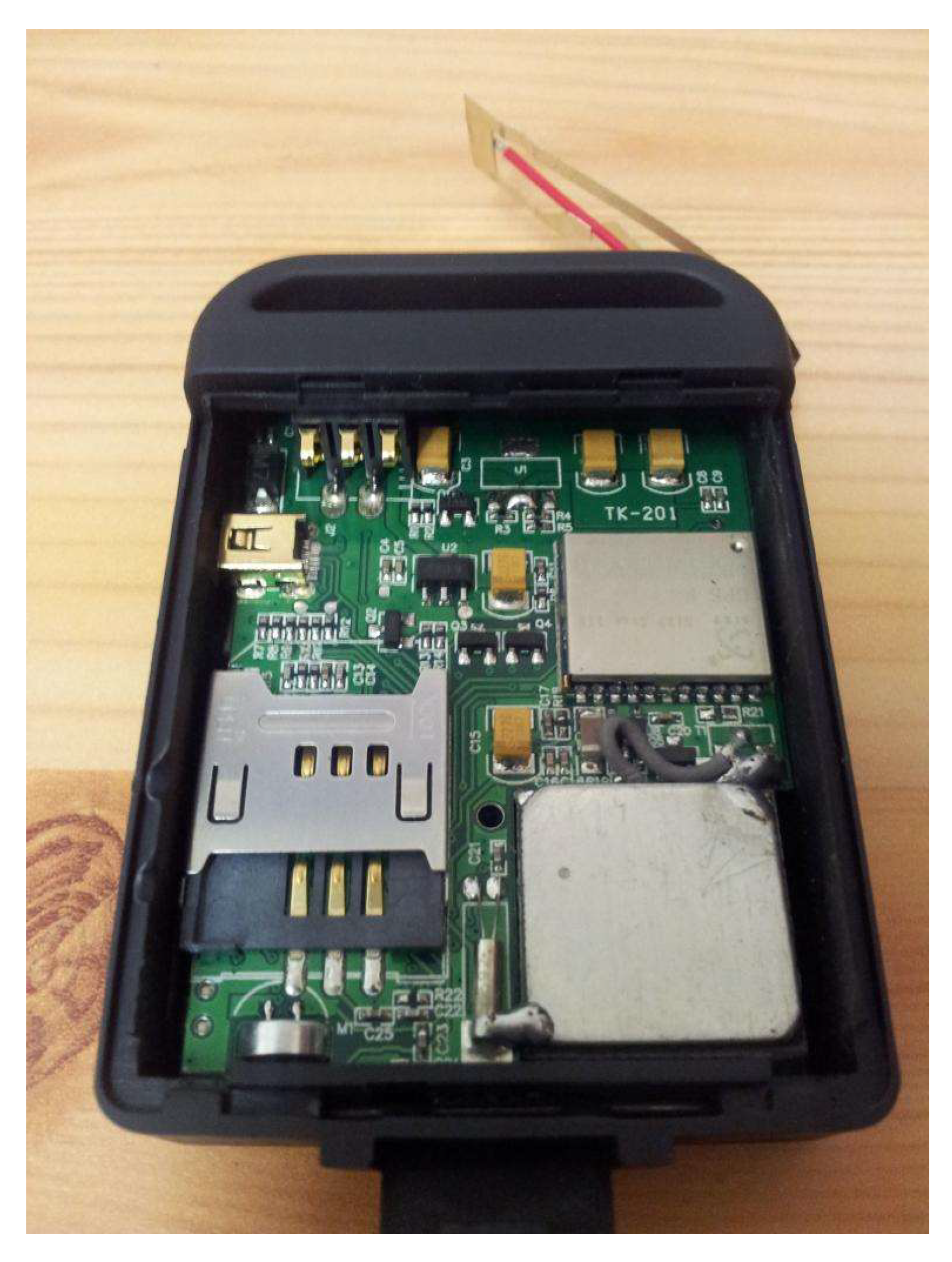
ThumbSat has its own space flight-qualified GPS and custom-made (in-house) “Rattatosk” UHF transceiver, but for redundancy, a backup GPS/GSM tracker was added to this demonstrator’s payload. GPS/GSM trackers use the cell phone network to report position information by text or data. The TK102B tracker (Figure 15) was selected as it is small and low mass, and has been successfully used on several of the team’s HAB missions. It cannot communicate above ~3.5km altitude, but can be used to pinpoint the payload once it has landed. The tracker requires a SIM card, the SIM from EE was selected as this operator claims to provide coverage over 99% of the UK.
The same battery pack as the video camera was selected, for the same reasons.
Electromagnetic Compatibility (EMC) is a challenge when incorporating a digital video camera into a small volume close to equipment that is sensitive to RF, such as this tracker, because the rapid transfer of data in the camera causes conducted and radiated electrical noise. Therefore, means of protection, such as aluminium foil covers to shield against radiated emissions and capacitors to filter conducted noise were incorporated into the system, based on trial and error.
4.5. Release Mechanisms
There are two release mechanisms, the first separates the payload from the balloon to allow the payload to free-fall, and the second deploys the parawing from its container by releasing a cap that holds the wing in the container. When released, the wing is pushed up by a spring that has a maximum preload of 70 N, imparting sufficient velocity to separate the wing from the capsule. The team has extensive experience of shape memory alloy (SMA) actuators, these provide an extremely low mass and volume, high-reliability method for hold-down and release mechanisms. A typical use of shape memory wire is as a force actuator. When a stretched SMA wire is heated beyond its transition temperature (in this case 70 °C) it returns to its original length with significant force, typically providing a reliable recovery movement of 2–3% of the original wire length. The 150 µm diameter wire used provides 3.2 N force. In this project, the wire was used as a pin-puller and for simplicity, to take advantage of the recovery strain and long capsule length, a simple ~150 mm long wire was used and looped around to give approximately 3 mm displacement of a pin. The pin held a loop of line for both actuators.
As the actuators rely on reaching a specific temperature, and as the temperature at the expected operation altitude is approximately −55 °C, the mechanisms were tested on the ground by cooling the entire assembly with an industrial cooling spray that lowered the temperature to <−50 °C.
As part of the development of this mechanism, tests were carried out with silicone sheathing (Figure 16) covering the SMA wire. This insulates the wire so it requires less power to actuate, has consistent and repeatable performance and timing, and protects other instruments from the hot wire. The principle of sheathing the SMA this way is potentially useful for actuating future mechanisms, including for Venus. This is the first time that sheathing has been used in this way, to the team’s knowledge.
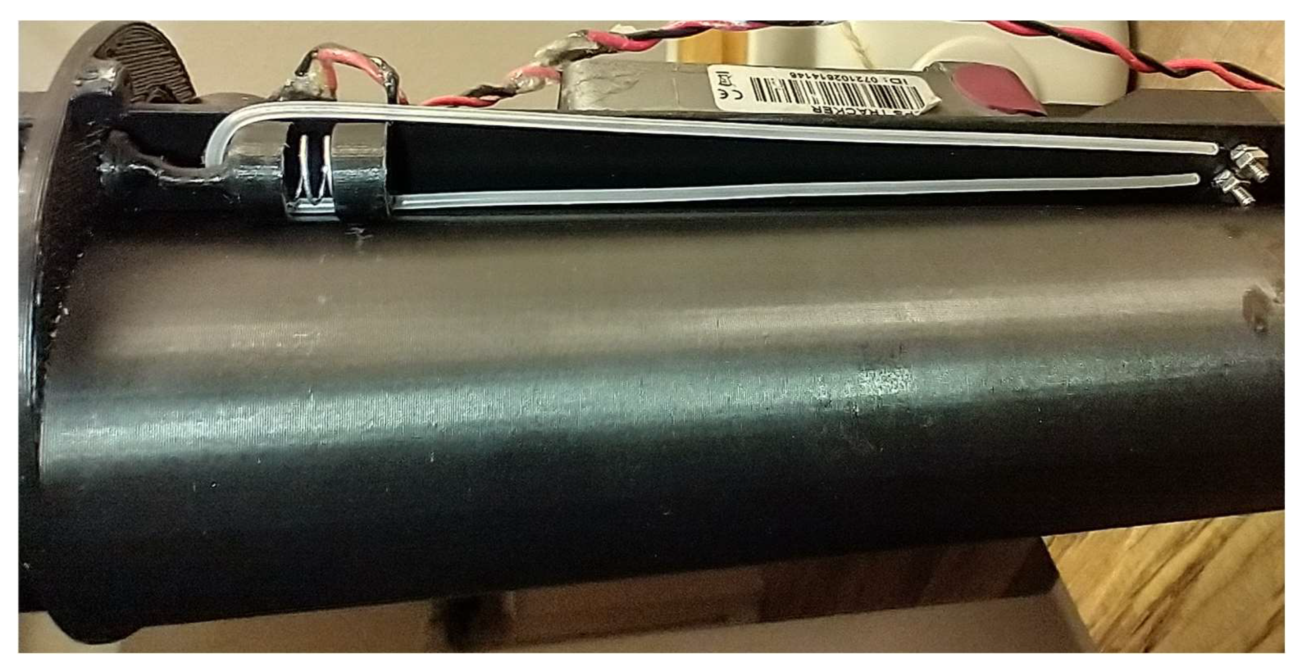
The mechanism for the stowed parawing hold-down and release is presented in Figure 17. The thin high-tensile strength lines hold the circular “cap” closed. When the pin (visible in the hole in the lug to the right of the capsule) is pulled, the loop is released, allowing the cap to open. The lug containing the pin that releases the payload from the balloon is visible to the left of the capsule.
4.6. Structure
The supporting structure consists of:
- A dense nose tip mass, machined from Alloy 600 stainless steel, with a density of 8.42 g/cm3, to provide aerodynamic stability by positioning the centre of mass ahead of the centre of pressure.
- A casing (Figure 18), 3D printed using ABS material, coloured bright orange for greater visibility to aid recovery.
5. Ground Stations
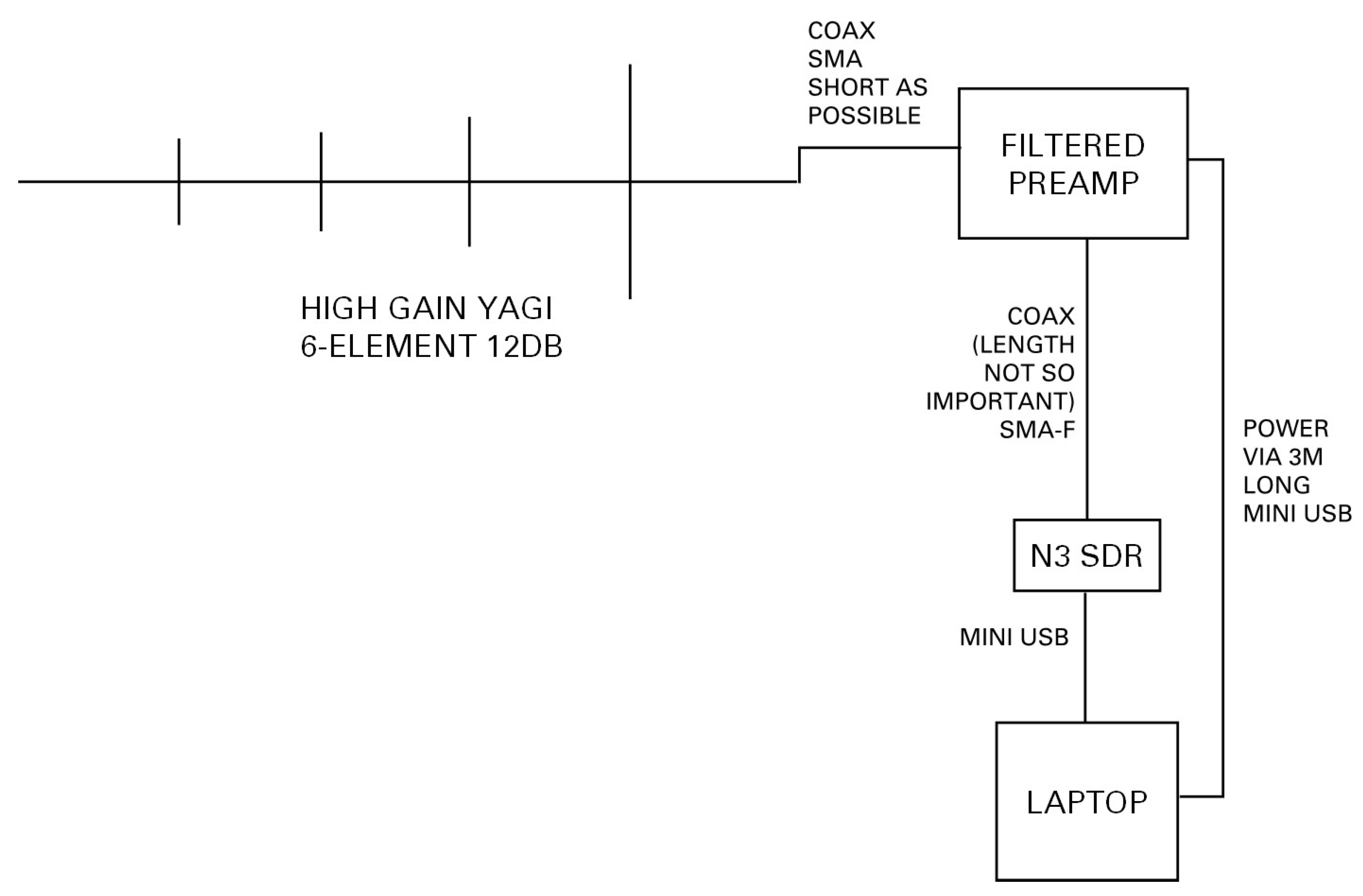
The ground stations (Figure 21 and Figure 22) are based around the ThumbNet “N3” Software-Defined Radio (SDR) receiver that was specially created by ThumbSat to donate globally to schools. The receivers are designed to be versatile—they can be used for many things other than ThumbSat reception—and robust—they were the first mass-produced SDR receivers to contain a high-performance temperature-compensated crystal oscillator to give stable operation over a wide range of temperatures.
In SDR, the receiver collects RF signals across a broad band, and the user’s computer processes these signals. To do this, the ThumbSat system uses the software:
- SDR#—PC-based Digital Signal Processing application for Software Defined Radio
- VBCable—a virtual audio cable
- DL-Fldigi—sound card decoding software. It takes the audio from the receiver and decodes the signal. In other HAB projects, it sends the telemetry via the internet to a server running other HAB software, but this facility is not used here.
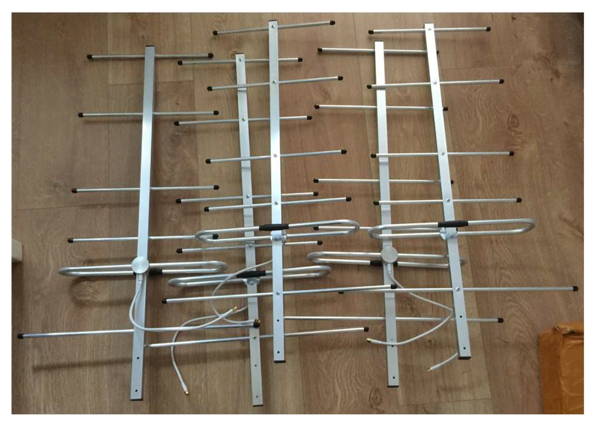
Each ground station system is specifically tuned for ThumbSat operations by the addition of a 400–403 MHz filtered pre-amplifier and custom-built directional “Yagi” antenna tuned to the ThumbSat frequency of 400.6 MHz (Figure 23).
6. Flight Plan
The balloon flight, capsule drop, and parawing descent were planned to take place over land and unpopulated areas in case any part of the recovery systems failed and to provide suitable ground locations for the logistics of launch and recovery. The team has established a set of launch sites to take advantage of the winds, to reverse-engineer the flight from the required landing point/flight trajectory to the launch point. For this mission, the flight was planned to take place over Upper Teesdale in the North of England, with a launch location at Appleby Grammar School.
As the UK’s high altitude winds are generally from the west, a regular launch site is used that is to the west of the flight area. However, winds have been unusual over the past 18 months, giving fewer launch opportunities. Wind speed is also important, lower speed upper-air winds are preferred so that the payload is not carried so far that it drifts over more populated areas, or out to sea beyond the east coast.
For all flights, “exemptions” are obtained from the Civil Aviation Authority (CAA) in batches, and each flight must be reported to the CAA one week in advance, so that they can issue a Notice to Airmen (NOTAM).
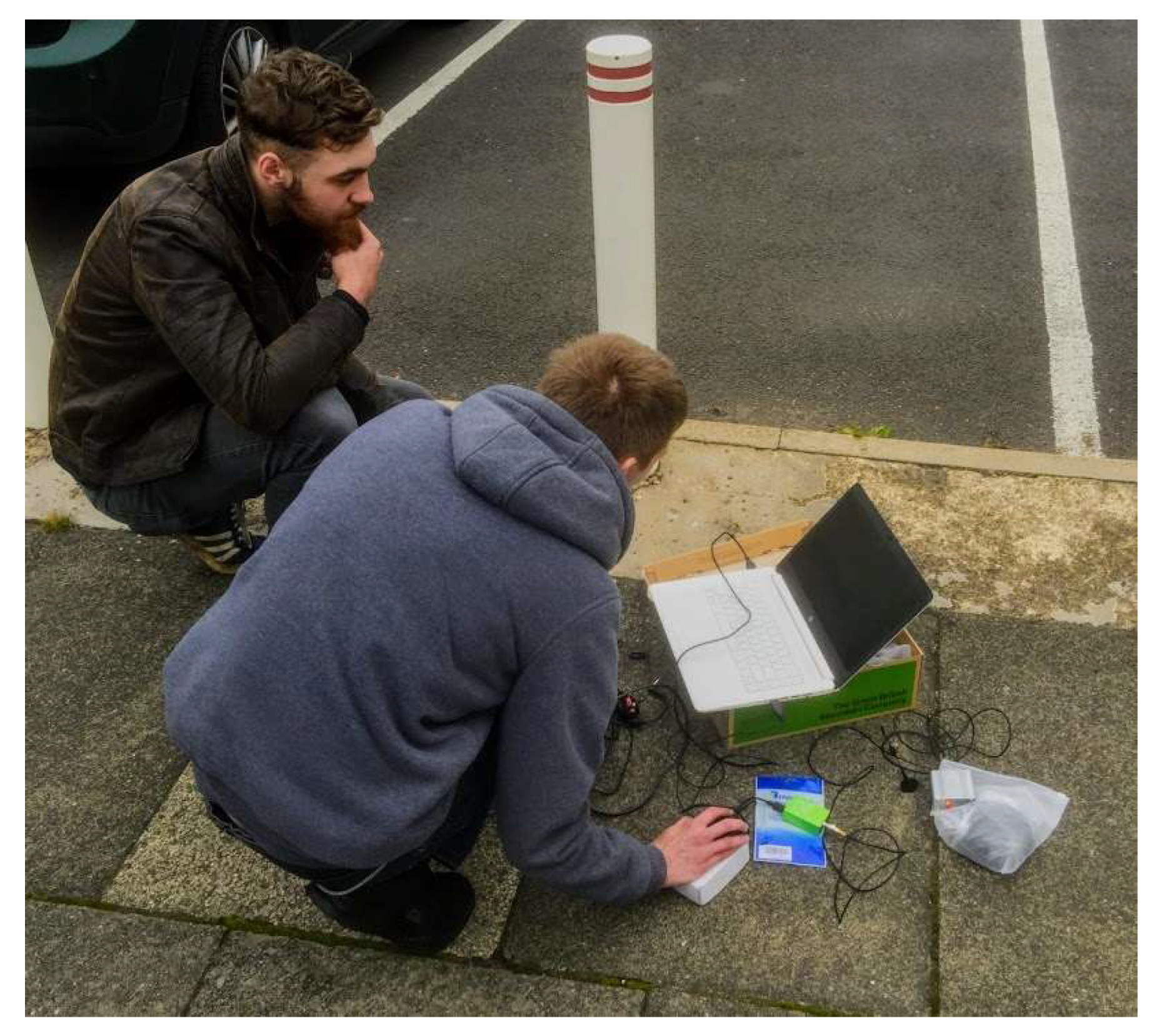
The ground station sites were selected to give optimum coverage over the flight region—the balloon launch team operated a mobile ground station, and fixed ground stations were established in Teesdale, Spennymoor, and the tall tower on the campus of Teesside University in Middlesbrough.
6.1. Balloon Flight Simulation
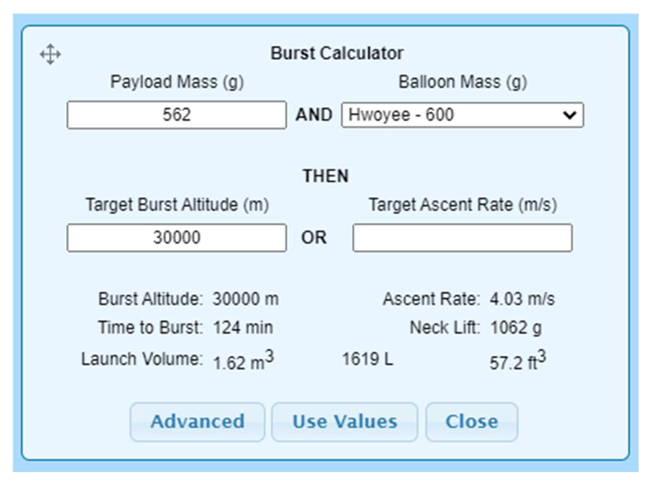
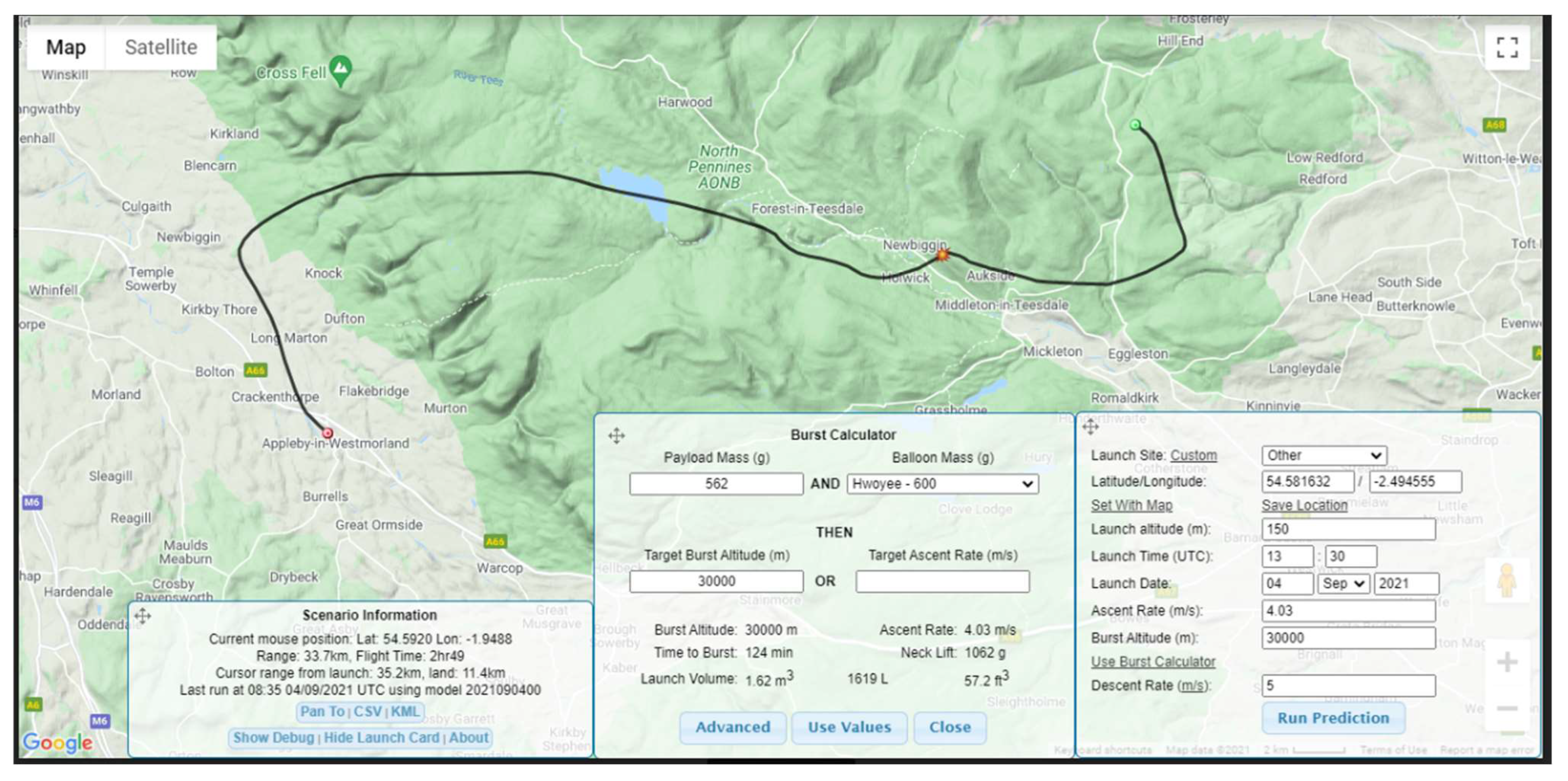
To fly the balloon on an accurate trajectory to a suitable drop location, a combination of the University of Southampton [9] and Cambridge University’s [10] balloon flight planners was used. The Cambridge planner was used to predict balloon burst altitude and required lift (Figure 24), and both planners were used to combine the balloon and payload properties with the forecast winds at altitude to generate an estimated trajectory (Figure 25). Balloon flight simulations have been found to be reasonably accurate up to 10 days in advance, and very accurate within 24 h of the flight. For this team’s work, simulations are always carried out with the latest wind information, immediately before the flight, so that final adjustments to fill gas (and hence lift) and timings can be used to optimise the trajectory.
6.2. First Flight Report
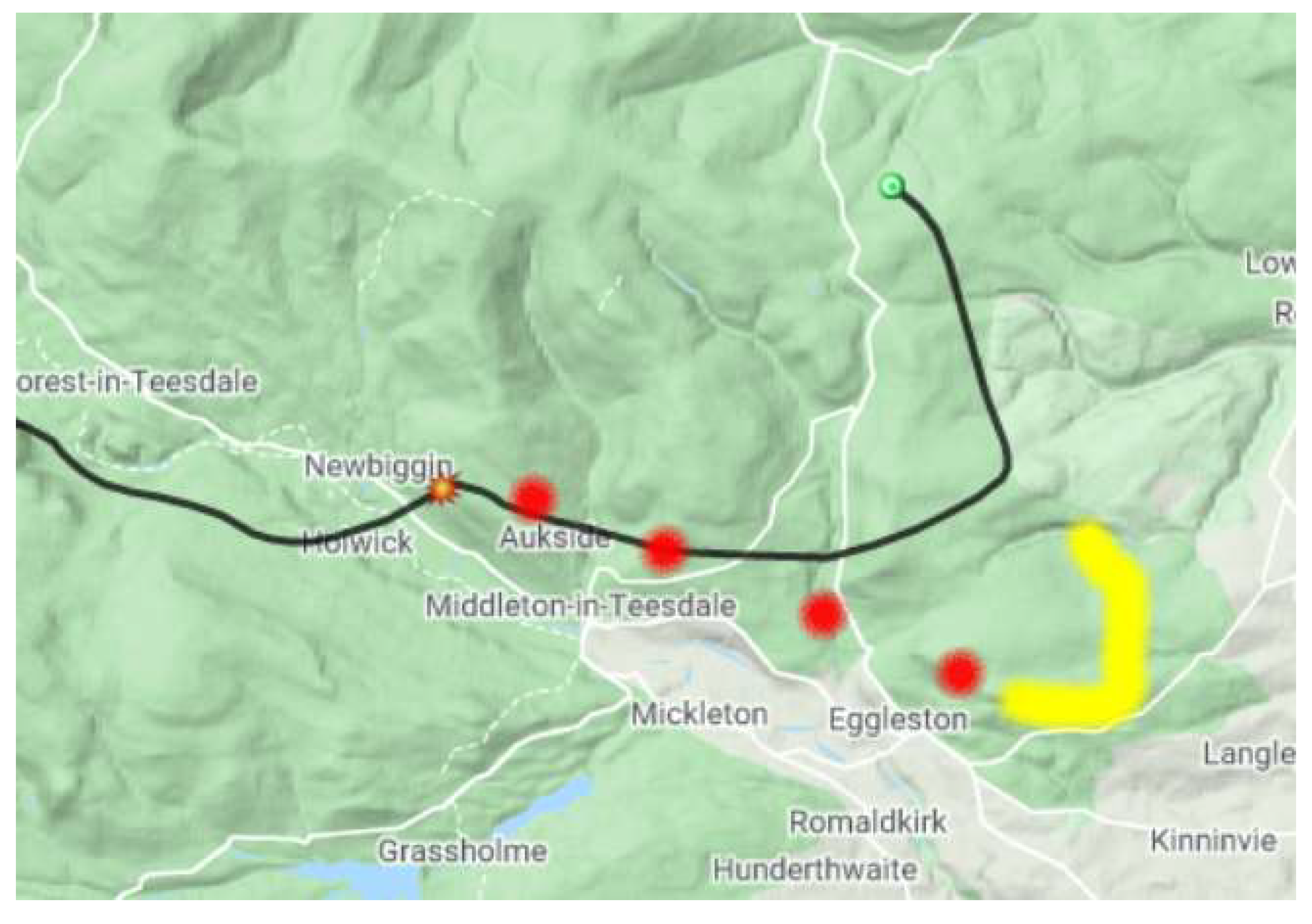
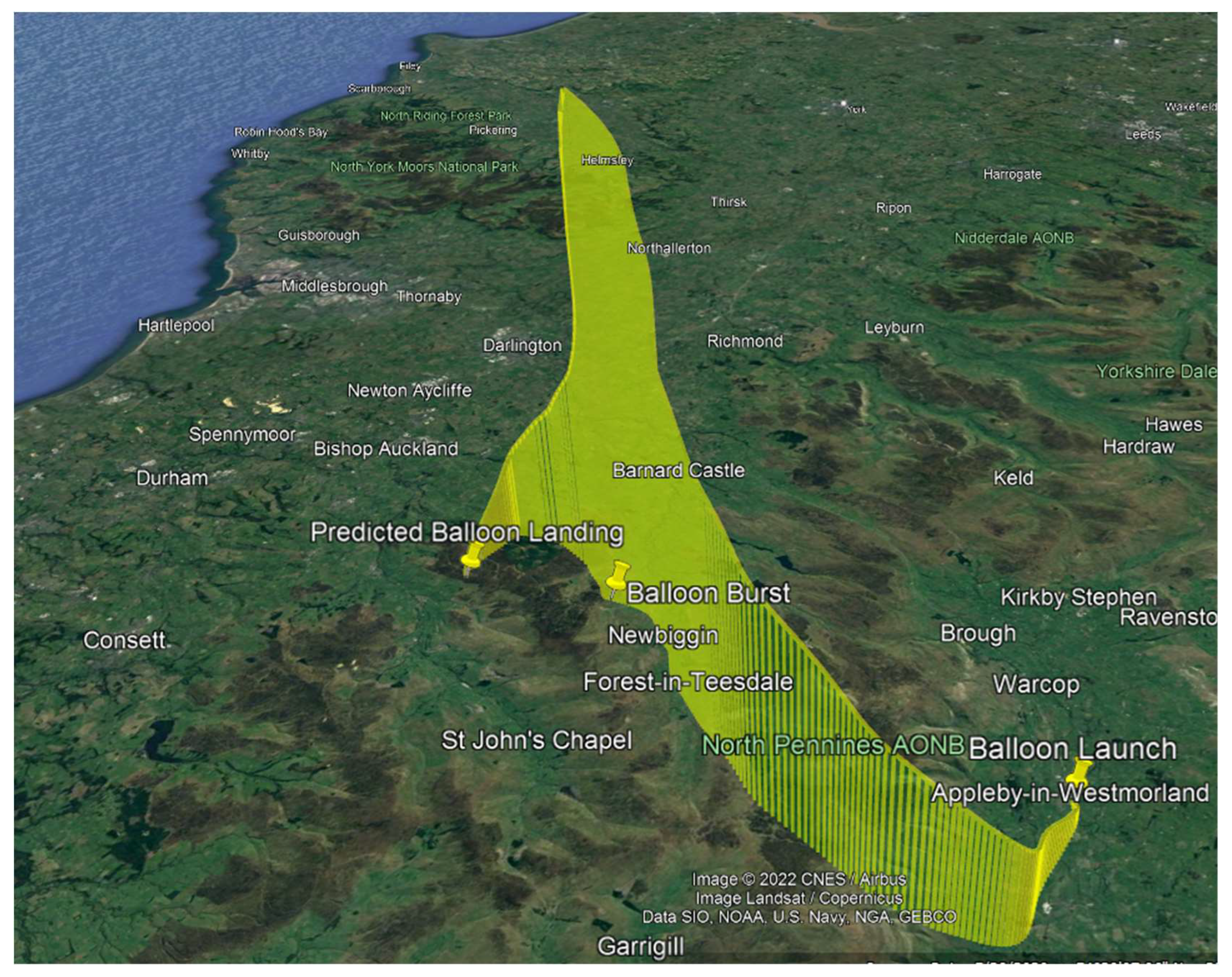
The initial flight ascended at the rate of climb predicted and followed the ground track as predicted. Figure 28 shows the planned trajectory (black line), the actual trajectory (red dots) and the estimated descent trajectory (yellow line). Figure 29 shows the 3-dimensional plot of the predicted trajectory.
However, the balloon continued to travel beyond the expected burst location, and ascended to 31 km, where it burst, as expected for this size of balloon and amount of fill gas.
After the balloon burst, even if the parawing had not deployed, the backup parachute was expected to slow down the descent. However, the payload descended more rapidly than planned and communication was lost with the payload below 709 m altitude.
Analysis of First Flight
The testing demonstrated that the capsule, payload, wing, ThumbSat and all key components should have performed as required on the planned flight. The balloon and payload ascended and followed the trajectory as expected. UHF data from ThumbSat was received as expected, from the furthest ground station at a slant range of 60 km.
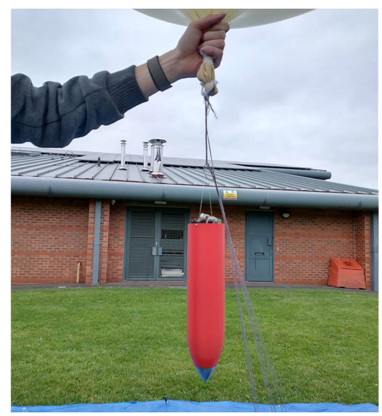
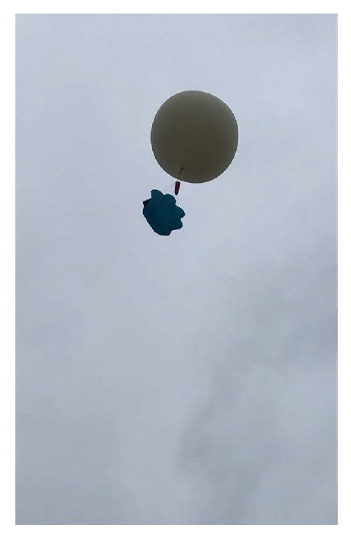
Upon reviewing the images from the launch team, it could be seen that the backup parachute (not part of the systems being tested) was inadvertently connected so that rather than being in-line between the balloon and the main payload, it was allowed to dangle down beneath the payload (Figure 30).
The lines of the parachute would therefore interfere with the deployment of the parawing. Data showed that the ThumbSat had triggered the release mechanism, but the wing had not deployed. Once the balloon burst, the payload and remains of the balloon probably dropped straight down into the backup parachute, preventing it from opening fully, and causing the whole assembly to descend and land more rapidly than expected. This appears to have caused the backup GPS/GSM tracker to fail, so there was no means to accurately locate the payload. A thorough ground search of the predicted landing area was carried out, but the payload was not recovered, and therefore no video of the flight was retrieved.
6.3. Second Flight Report
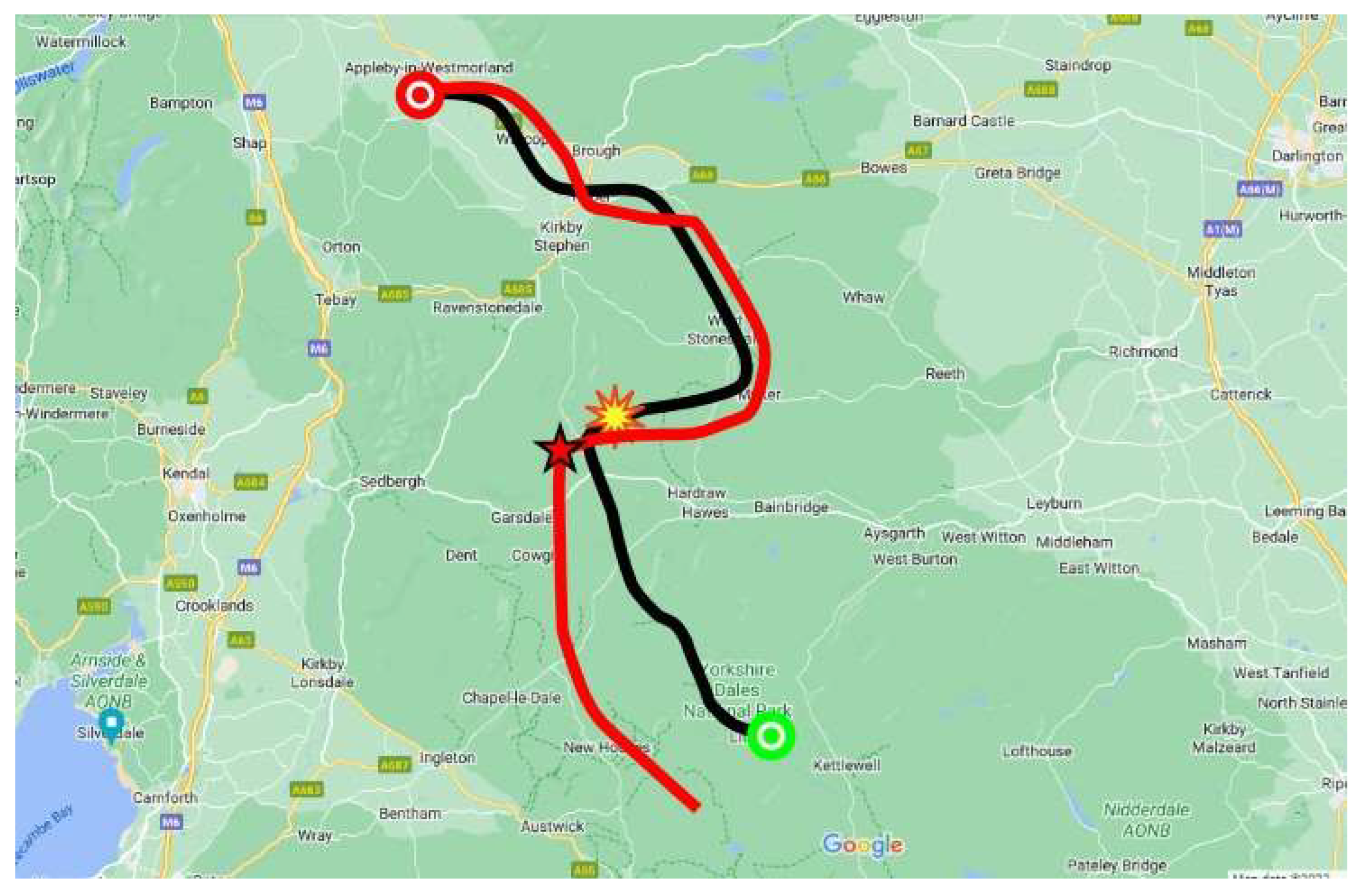
The second flight was launched on 19 June 2022. The configuration and procedures were essentially the same as the first flight, but with some small differences in wing/deployer hardware and ThumbSat firmware. These changes included resetting the trim of the parawing and simplifying the flight algorithm. Good telemetry was received throughout the flight. The flight ascended at the rate of climb predicted and followed the ground track as predicted. Figure 31 shows the planned trajectory (black line) and actual trajectory (red line). The capsule release from the balloon is indicated by the red star.
Analysis of Second Flight
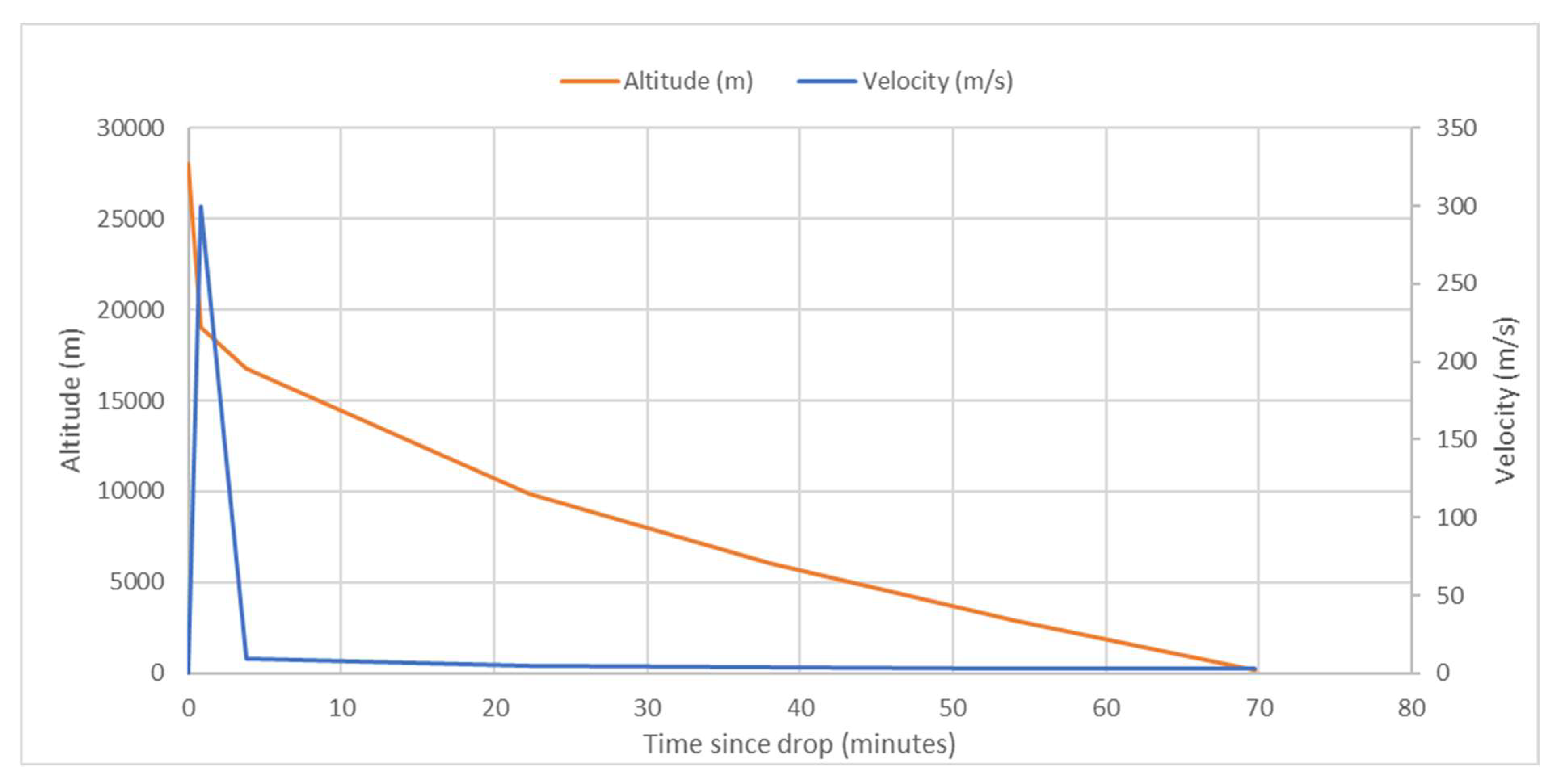
Telemetry showed that the wing release was triggered 47 s after the capsule separation from the balloon was initiated by the ThumbSat, meaning that the ThumbSat had determined the descent velocity as being greater than Mach 1. The descent profile is presented in Figure 32. During the 3 min after wing deployment, the capsule vertical velocity rapidly decreased to 10 ms−1 at an altitude of 16,782 m and reached a low altitude terminal velocity of <3 ms−1. The wing is unguided and so in principle may fly in any direction relative to the wind, so the glide ratio can only be approximated from estimated winds. In this case, the average glide ratio appeared to be between 2.5:1 and 3:1.
The missions for this project have been designed and planned to be recoverable, so that the onboard footage from the video camera can be retrieved and the flight hardware inspected. However, considering the winds at altitude, the safety requirements (not to overfly populated areas) and the benefits of obtaining results quickly, this mission was deliberately flown to be “sacrificial”. It was known that the descent would take place over dense vegetation and undulating terrain so that it could not be tracked in its final stages or easily located. The payload has not yet been retrieved. This was considered acceptable as enough data could be obtained via telemetry to determine that the wing successfully deployed and that the rest of the hardware worked as expected, allowing the basic flight characteristics to be determined.
Summary of challenges and goals and the results of this test programme:
- The deployment of the parawing system proposed for Venusian payload delivery was tested, and telemetry showed that the wing successfully deployed at >Mach 1.0 to give a stable flight.
- The ThumbSat including the battery continued to operate and transmit data at a slant range of 60 km at temperatures between −55 °C and +30 °C and <10 mbar to 1 atmosphere.
7. Conclusions, Re-Flight and Future Work
A mission has been designed and created, to demonstrate the deployment of a payload on a parawing in the Earth’s upper atmosphere, in circumstances similar to an opportunistic Venusian delivery.
The video data from the first flight were not retrieved, but the ThumbSat’s telemetry signal was successfully received from several ground stations, and all flight procedures were pulled through.
The team rebuilt the demonstrator, made several improvements and re-flew the mission. Telemetry showed that the wing successfully deployed, and allowed the flight characteristics to be determined, suggesting that this method is feasible for Venusian payload delivery.
There are several recommended steps that can be taken to further prepare the design and hardware for a Venus mission.
7.1. Data-Building
A single successful flight does not demonstrate full reliability of this deployment technique and hardware. It would be beneficial to fly multiple flights with different configurations and parameters (payload mass, wing size, wing reefing), to build up enough data to gain confidence. Now that payloads have been created and demonstrated for this mission, and the techniques pulled-through, this will be relatively straightforward to achieve.
7.1.1. Kapton Venus-Type Wing
Although outside the scope of this mission, the team experimented with a Kapton parawing of the type that is suitable for Venus. Several steps have been identified that are required before the production of flight models:
- Investigate electrostatic issues for tightly folded and rapidly deployed Kapton.
- Investigate creasing in Kapton to ensure that long-term creasing does not reduce the structural strength or deployment performance.
- Soak wing in sulphuric acid fog and test its strength.
7.1.2. Deployment Experiments
- If deployment is unstable with the relatively low spring ejection force, experiment with the deployment of the parawing using an ejection charge.
- Investigate reefing of the wing if necessary.
7.1.3. Venus Payload Testing
Supplementary Materials
The following supporting information can be downloaded at: https://www.mdpi.com/article/10.3390/aerospace9100573/s1, File S1: Drop calculator MASTER.xlsx.
Funding
This research was funded by Scoutek Ltd. and the Massachusetts Institute of Technology.
Institutional Review Board Statement
Not applicable.
Informed Consent Statement
Not applicable.
Data Availability Statement
All data are published together with the paper as Supplementary Materials.
Acknowledgments
The author thanks the Venus Life Finder Mission team for useful discussions, Antonio Hernandez at ThumbSat, Spirent Communications (UK) for the use of their GPS simulation facilities and the Steel River Rocketeers (UK)—Callum McClintock, Nathan Bell, Owain Madge, Alaexandra Kostryukova, Ahalya—for their mission support.
Conflicts of Interest
The authors declare no conflict of interest.
Abbreviations
| AIV | Assembly, Integration and Verification |
| CAA | Civil Aviation Authority |
| COTS | Commercial Off The Shelf |
| EMC | Electromagnetic Compatibility |
| FRR | Flight Readiness Review |
| GNSS | Global Navigation Satellite System |
| HAB | High Altitude Balloon |
| HD | High Definition (usually related to camera sensor) |
| IMU | Inertial Measurement Unit |
| LEO | Low Earth Orbit |
| LOVE | Life on Venus Expedition |
| NOTAM | NOTice to AirMen |
| NPW(21) | NASA ParaWing (version 21) |
| SDR | Software-Defined Radio |
| SMA | Shape Memory Alloy (Nitinol wire in this report) |
| TBC | To Be Confirmed |
| TBD | To Be Determined |
| UHF | Ultra High Frequency (related to transceiver) |
References
- Seager, S.; Petkowski, J.J.; Carr, C.E.; Grinspoon, D.; Ehlmann, B.; Saikia, S.J.; Agrawal, R.; Buchanan, W.; Weber, M.U.; French, R. Venus Life Finder Mission Study. arXiv 2021, arXiv:2112.05153. [Google Scholar]
- Whitehead, S. ThumbSat/ThumbNet—Promoting Science, Technology, Engineering, Art and Mathematics. Available online: https://www.thumbsat.com/ (accessed on 1 July 2022).
- Justh, H.L. Venus Global Reference Atmospheric Model (Venus-GRAM), Version 1.0; Environmental Science Earth Air Space Exoplanet; NASA: Washington, DC, USA, 2005. [Google Scholar]
- Biegert, M. Drag Coefficient From A Ballistic Drop Table. Available online: https://www.mathscinotes.com/2016/02/drag-coefficient-from-a-ballistic-drop-table/ (accessed on 1 July 2022).
- Atmosphere of USS. US Standard Atmosphere; National Oceanic and Atmospheric Administration: Washington, DC, USA, 1976. [Google Scholar]
- Kontinos, D.A.; Wright, M.J. Introduction: Atmospheric entry of the stardust sample return capsule. J. Spacecr. Rocket. 2010, 47, 705–707. [Google Scholar] [CrossRef]
- Rogallo, F.M. Nasa Research on Flexible Wings; NASA Langley Research Center: Hampton, VA, USA, 1967. [Google Scholar]
- X-Plane. X-Plane 11 Flight Simulator; Laminar Research: Columbia, SC, USA, 2022. [Google Scholar]
- Chambers, P.; Zapponi, N.; Sobester, A. ASTRA Balloon Flight Simulation Python Tool 2017. Available online: https://github.com/sobester/astra_simulator (accessed on 1 July 2022).
- Greig, A. CUSF Landing Predictor 2.5. Cambridge Univ. Sp. Flight 2010. Available online: https://predict.habhub.org/ (accessed on 1 July 2022).
- Knapczyk-Korczak, J.; Szewczyk, P.K.; Ura, D.P.; Bailey, R.J.; Bilotti, E.; Stachewicz, U. Improving water harvesting efficiency of fog collectors with electrospun random and aligned Polyvinylidene fluoride (PVDF) fibers. Sustain. Mater. Technol. 2020, 25, e00191. [Google Scholar] [CrossRef]
- Fernandez, D.M.; Torregrosa, A.; Weiss-Penzias, P.S.; Zhang, B.J.; Sorensen, D.; Cohen, R.E.; McKinley, G.H.; Kleingartner, J.; Oliphant, A.; Bowman, M. Fog water collection effectiveness: Mesh intercomparisons. Aerosol Air Qual. Res. 2018, 18, 270–283. [Google Scholar] [CrossRef] [Green Version]
- Schemenauer, R.S.; Joe, P.I. The collection efficiency of a massive fog collector. Atmos. Res. 1989, 24, 53–69. [Google Scholar] [CrossRef]
- Shi, W.; van der Sloot, T.W.; Hart, B.J.; Kennedy, B.S.; Boreyko, J.B. Harps Enable Water Harvesting under Light Fog Conditions. Adv. Sustain. Syst. 2020, 4, 2000040. [Google Scholar] [CrossRef]
Figure 1.
Concept schematic (not to scale).

Figure 2.
G7 bullet shape (top) and drop test capsule shape.

Figure 3.
G7 shape Drag Coefficient versus Mach number [4].
Figure 3.
G7 shape Drag Coefficient versus Mach number [4].

Figure 4.
Best fit data for Earth atmosphere [5] used in calculation of capsule drop performance.
Figure 4.
Best fit data for Earth atmosphere [5] used in calculation of capsule drop performance.

Figure 5.
Calculated altitude and velocity profile for capsule drop.

Figure 6.
Payload schematic.

Figure 7.
V8 version ThumbSat, GPS patch antenna at lower middle, UHF antenna in centre.

Figure 8.
NPW21 parawing.

Figure 9.
Early Prototype Bug Mylar parawing in flight.

Figure 10.
LOVE-Bug Para Wing Variant with tail drag device—simulation.

Figure 11.
Kapton parawing initial planform.

Figure 12.
Prototype Kapton wing being flight-tested as a kite.

Figure 13.
Packed parawing.

Figure 14.
808#32 camera circuit board front (a) and rear (b).

Figure 15.
TK102B GPS/GSM tracker module—antenna at top.

Figure 16.
Shape memory alloy wire with silicone sheath.

Figure 17.
Rear of capsule, with circular parawing container “cap” at top, pinpuller lugs at right and left.
Figure 17.
Rear of capsule, with circular parawing container “cap” at top, pinpuller lugs at right and left.

Figure 18.
3D printed casing and stainless steel tip mass.

Figure 19.
Component carrier with camera, GPS and battery packs visible at top.

Figure 20.
Component carrier, with MOSFET, SMA wires and pinpuller visible at top, ThumbSat at lower right, ¼ wavelength monopole antenna (yellow) in the centre.
Figure 20.
Component carrier, with MOSFET, SMA wires and pinpuller visible at top, ThumbSat at lower right, ¼ wavelength monopole antenna (yellow) in the centre.

Figure 21.
Ground station setup.

Figure 22.
Setting up the ground station, with ThumbNet “N3” SDR receiver (green) to lower right.

Figure 23.
Ground station antennas.

Figure 24.
Typical use of Cambridge University balloon fill and burst planner.

Figure 25.
Typical flight plan with data used for prediction (Cambridge University planner).

Figure 26.
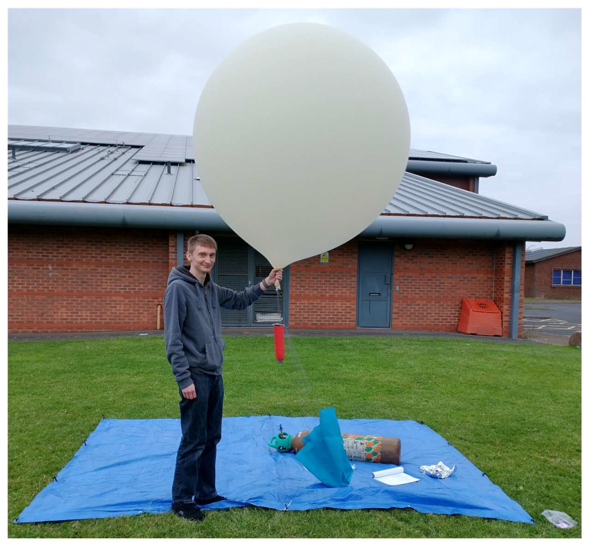
Capsule payload suspended beneath the balloon.

Figure 27.
Balloon and payload ready for launch.

Figure 28.
Predicted trajectory (black line), actual trajectory (red dots) and estimated descent (yellow line).
Figure 28.
Predicted trajectory (black line), actual trajectory (red dots) and estimated descent (yellow line).

Figure 29.
Three-dimensional presentation of predicted flight trajectory.

Figure 30.
Balloon ascent, showing that the recovery chute (blue) was not in-line between balloon and capsule.
Figure 30.
Balloon ascent, showing that the recovery chute (blue) was not in-line between balloon and capsule.

Figure 31.
Predicted trajectory (black line) and actual trajectory (red line).

Figure 32.
Descent profile.


Table 1.
List of components of the tested payload.
| Items under Test | Support Systems |
|---|---|
| Parawing | 650 g balloon |
| ThumbSat + flight-type battery | Backup parachute (45 g) |
| High definition camera | |
| Backup tracker | |
| Release mechanisms |
Publisher’s Note: MDPI stays neutral with regard to jurisdictional claims in published maps and institutional affiliations. |
© 2022 by the author. Licensee MDPI, Basel, Switzerland. This article is an open access article distributed under the terms and conditions of the Creative Commons Attribution (CC BY) license (https://creativecommons.org/licenses/by/4.0/).
Share and Cite
MDPI and ACS Style
Whitehead, S. LOVE-Bug Deployment Demonstrator. Aerospace 2022, 9, 573. https://doi.org/10.3390/aerospace9100573
AMA Style
Whitehead S. LOVE-Bug Deployment Demonstrator. Aerospace. 2022; 9(10):573. https://doi.org/10.3390/aerospace9100573
Chicago/Turabian StyleWhitehead, Shaun. 2022. "LOVE-Bug Deployment Demonstrator" Aerospace 9, no. 10: 573. https://doi.org/10.3390/aerospace9100573
Note that from the first issue of 2016, this journal uses article numbers instead of page numbers. See further details here.