Article

Parametric Study of a Composite Skin for a Twist-Morphing Wing

Department of Mechanical Engineering, California State University, Northridge, Northridge, CA 91330, USA
*
Author to whom correspondence should be addressed.
Aerospace 2021, 8(9), 259; https://doi.org/10.3390/aerospace8090259
Submission received: 9 August 2021 / Revised: 5 September 2021 / Accepted: 6 September 2021 / Published: 13 September 2021
(This article belongs to the Special Issue Advances in Aerospace Sciences and Technology II)

Abstract

:
Although the benefits of morphing wings have been proven in many studies in the last few decades, the wing skin design remains one of the challenges to advancing and implementing the morphing technology. This is due to the conflicting design requirements of high out-of-plane stiffness to withstand aerodynamic loads and low in-plane stiffness to allow morphing with the available actuation forces. Advancements in the design of hybrid and flexible composites might allow for design solutions that feature this balance in stiffness required for this application. These composites offer new design parameters, such as the number of plies, the fiber-orientation angle of each ply in the skin laminate, and the spatial distribution of the plies on the skin surface. This paper presents a parametric study of a composite skin for a twist-morphing wing. The skin is made of periodic laminated composite sections, called “Twistkins”, integrated in an elastomeric outer skin. The twisting deformation is localized in the elastomeric sections between the Twistkins. The design parameters considered are the number of plies in the composite Twistkins, the fiber-orientation angle of the plies, the torsional rigidity of the elastomer, the width ratio, and the number of elastomeric sections. The computational analysis results showed that the torsional compliance can be increased by increasing the width ratio, decreasing the number of elastomeric sections, number of composite plies and the elastomer’s torsional rigidity. However, this would also lead to a decrease in the out-of-plane stiffness. The nonlinearity and rates at which these parameters affect the skin’s behavior are highlighted, including the effect of the fiber-orientation angle of the laminate plies. Hence, the study guides the design process of this twist-morphing skin.

1. Introduction

Modern aircrafts use discontinuous flight control surfaces, such as ailerons, flaps, slats, and elevators, to maneuver during flight. These control surfaces alter the geometry of the wing or tail stabilizers to affect yaw, pitch, and roll. The presence of these traditional discrete control surfaces in the wing results in vortex formation, and hence generation of unwanted drag from the gaps and hinges between the control surface and the wing [1]. Unlike birds’ wings that can seamlessly and flexibly change in shape, traditional wings are incapable of such adaptation to various flight conditions. Commercial airplane wings are designed for specific conditions that the airplane experiences for the most of its flight. Hence, they are most efficient during cruising, but the performance during other flight scenarios, like takeoff and landing, is sub-optimal. Smaller aircrafts, like unmanned aerial vehicles (UAVs), exhibit various flight conditions, and therefore need wings that can adapt to those conditions while remaining aerodynamically efficient [2]. Lightweight continuous morphing wings capable of transforming in flight are desired for improving the overall flight performance and efficiency.
There are three major categories of wing morphing: planform, out-of-plane, and airfoil morphing [3]. Planform morphing includes resizing the span and chord lengths and modifying the sweep angle [4]. Out-of-plane morphing includes twisting, change in dihedral angle, camber-morphing, and span-wise bending [5,6,7]. Airfoil morphing includes reshaping the airfoil profile and thickness. It has been shown that each type of shape morphing enabled in a wing can improve the aerodynamic efficiency of the aircraft in specific flight conditions. For example, Joshi et al. [8] compared the predicted performance of a BQM-34 Firebee unmanned target drone aircraft with a fixed wing, a wing capable of airfoil morphing, and a wing capable of planform morphing. Eleven different flight conditions were compared, and the performance of the aircraft was significantly improved with the use of morphing wings in most of the considered conditions. Beaverstock et al. [9] quantified the improved performance in aerodynamic efficiency and range by using span-morphing and camber-morphing wings on a UAV at various speeds.
The Wright Flyer I, in 1903, had wings made of fabric and wooden ribs, and was able to twist its wings to roll [10]. Since then, the fabric wings that were capable of twist-morphing were replaced by a more rigid structure to support the increased demand of higher cruise speeds and larger aerodynamic loads [11]. Twist-morphing is one of the most practical morphing techniques. This type of out-of-plane morphing allows for a seamless change in the angle of attack (AOA) along the span of the wing. Hence, it can decrease a wing’s induced drag by removing the discontinuous surfaces of ailerons and flaps [12]. Twist-morphing can also improve roll and pitch performance, increase the amount of lift generated, and expand the flight envelope of the aircraft [13]. Twist-morphing can be applied gradually along the entire span of the wing, or locally concentrated in a single segment. Currently, one of the most difficult challenges in designing a morphing wing is the outer skin. The reason for this is that it must satisfy two conflicting requirements: high out-of-plane stiffness and low in-plane stiffness. This means that the skin must be stiff enough to withstand aerodynamic pressure loads while being sufficiently compliant for the morphing actuation [14,15]. Jenett et al. [16] designed a gradual twist-morphing wing that has modular elements to create a composite lattice structure. This lattice structure was placed between the ribs, which were made of carbon-fiber reinforced polymer (CFRP). The outer skin was constructed with overlapping strips of polyimide film that attach to the ribs. They showed that wing twist is an effective means to increase lift. Mistry et al. [17] examined a gradual twist concept for a helicopter rotor blade. The blade’s skin was made of CFRP and has c-channels bonded along the spanwise direction. The c-channels allow the inner aluminum ribs to rotate with the skin. Vos et al. [18] introduced a mechanism for controlling warp deformation. The wing skin has a slit at the trailing edge to create an open-section airfoil. This slit along with an internal warping control mechanism allow the wing to warp and create a gradual twist. A prototype of the wing was constructed with aluminum ribs which are free to rotate about an aluminum spar. A continuous CFRP skin covered the outside of the wing. The skin was not attached to the ribs but was free to slide over them during morphing. Alsaidi et al. [19,20] analyzed skins for multi-axial camber morphing wings made of lattice structures. Arena et al. [21] developed a multi-segment adaptive trailing edge morphing wing with skin made of hard segments and elastomeric layers supported by foam pieces at the locations of the hinges of the trailing edge segments. They analyzed the design statically and dynamically, computationally and experimentally.
Applying twist-morphing to strategic locations on the wingspan may be more desirable than a gradual twist over the entire span length [6,12]. By having the twist-morphing section in the middle of the wing, the rotating section will have a uniform AOA, further increasing the amount of lift generated. This will also allow for greater roll control [12]. Guiler and Huebsch [22] tested a swept wing tailless aircraft where twist-morphing only occurring at the outer third of the wing. The design used a rigid CFRP spar with a torque rod attached to the outermost rib. Multiple free-floating CFRP ribs covered with a latex skin were used. When compared with an elevon-equipped wing, the morphing wing showed a reduction in drag. Schlup et al. [6] designed an entire UAV, called MataMorph-2 or XM-2, without the use of any discrete control surfaces, relying on twist-morphing wings and camber-morphing horizontal and vertical stabilizers. The span of the wing had three sections, with twist-morphing localized in the middle section. The design consisted of Balsa wood ribs with polyurethane foam placed between the ribs. The entire section was then covered with a polyvinylidene chloride outer surface. Twist-morphing has gained importance for micro air vehicles (MAVs), as they fly in diverse environments and lack enough internal volume in their wings for traditional control surfaces. Garcia et al. [23] and Stanford et al. [24] presented MAVs with similar wing designs. The wings were made of a CFRP leading edge with CFRP strips that extend to the trailing edge. This was covered with a flexible material, either latex rubber or a thin plastic membrane. The twist is achieved by either a torque rod or string connected to a motor in the fuselage. It was demonstrated that roll rates and lift-to-drag ratios can increase with the use of twist-morphing in MAVs.
With the advancements in smart materials, like shape memory alloys (SMA) and piezoelectric materials, many researchers have been developing innovative methods of incorporating smart materials and compliant structures into morphing wings [5,12,25,26,27]. Barrett [25] showed that twist-morphing can be induced with the use of bimorph piezoelectric actuators. A polymer skinning material was used to cover the actuator and the CFRP ribs for a seamless surface. Elzey et al. [26] described a vertebrate-structured rib integrated with shape memory alloy (SMA) strips to achieve shape change. The vertebrate structure consisted of tubular elements linked together with cylinder-and-pin joints. Dual SMA strips were placed surrounding the tubular elements to create an antagonistic bending actuation. The skin was not bonded to the ribs so it may freely slide across the surface of the ribs. Bartley-Cho et al. [27] developed a trailing edge camber-morphing wing that can create twist-like effects using ultrasonic piezoelectric motors. Multiple hingeless control surface segments made up of a honeycomb core, aluminum trailing edge, and a silicone outer skin, were placed on a portion of the trailing edge. Each segment could be controlled individually, which resulted in a twisting behavior. Raither et al. [28] presented an adaptive smart structure with variable-stiffness morphing wing. The main structure and ribs were made of CFRP with polyvinyl chloride (PVC) webs. The PVC web can change its stiffness due to changes in temperature. The structure was covered with a CFRP skin. Rodrigue et al. [12] localized twist-morphing to the middle portion of the wing. The section near the fuselage remained fixed while the outermost section rotated uniformly. The morphing segment consisted of a smart soft composite structure. SMA wires were attached to a polylactic acid (PLA) frame and embedded in a polydimethylsiloxane (PDMS) mold. Testing showed an increase in the lift-to-drag ratio.
This paper presents a parametric study on a hybrid composite skin made of periodic CFRP strips, called “Twistkins,” that provide out-of-plane rigidity, covered by an elastomeric skin that allows for twist-morphing. The study aims to show the effects of all design parameters on the torsional compliance and out-of-plane stiffness, hence guides the design of such twist-morphing hybrid composite skin. Multiple finite element analysis (FEA) models were created for these studies. The rest of the paper is organized as follows: Section 2 describes the model and design variables. Section 3 and Section 4 present the torsional compliance and out-of-plane stiffness studies, respectively. Section 5 discusses all results and concludes the paper.

2. Model Description

The twist-morphing wing under consideration is shown in Figure 1a. It is divided into three sections: the fixed section close to the wing root, the twisting section where twist-morphing happens, and the rotation section close to the wing tip. This configuration is similar to the wing configuration of Rodrigue et al. [12] and Schlup et al. [6] (XM-2). The twist-morphing skin design under study in this work is shown in Figure 1b. It is composed of a repeated arrangement of stiff carbon-fiber reinforced polymeric (CFRP) airfoil-shaped sections, covered by an elastomeric skin. A CFRP section can be thought of as a stiff skin section combined with a wing rib that is able to rotate giving a twisted wing shape. Hence, we call it “Twistkin.” The locations where there is only elastomeric skin and no CFRP structure are called the “elastomeric sections.” The Twistkins are the locations where the elastomeric skin is supported by the CFRP sections.
A profile of one Twistkin can be seen in Figure 2. It has a spar support at the location of the maximum airfoil thickness. All Twistkins are restrained in their locations on a spar that runs through all spar supports. The spar functions as a torque rod, which is fixed to the last Twistkin in the twisting section and the entire rotating section. The spar is rotated via a rotating mechanism housed in the UAV fuselage, such as the one proposed by Schlup et al. [6]. The first Twistkin is attached to the fixed section while the other Twistkins are free to rotate about the spar. So, the Twistkins cannot translate spanwise, but can only rotate relative to the spar.
A model of the skin without the flexible elastomeric skin before and after twist-morphing can be seen in Figure 3.
The airfoil selected for the model was a NACA 0012 symmetric airfoil, but any other airfoil shape can be used instead. This airfoil is symmetric, hence has no camber, and has a maximum thickness of 12% of the chord length ( L c ). The NACA airfoil equation has the form:
y = ± 0.6 L c ( 0.2969 x 0.1260 x 0.3516 x 2 + 0.2843 x 3 0.1015 x 4 )
where x and y are the coordinates on the x- and y-axis, respectively. Equation (1) creates an open-section airfoil with a blunted trailing edge, unsuitable for CFD or FEA analysis. So, the equation was slightly altered to create a closed sharp trailing edge. The revised NACA airfoil equation is expressed as:
y = ± 0.59469 L c ( 0.29822 x 0.12713 x 0.35791 x 2 + 0.29198 x 3 0.10517 x 4 )
In the CAD model, the chord length, L c , is taken as 235 mm and the span length, L s , is 178 mm. The spar is located about 61 mm from the leading edge, which is 0.26 L c and it goes through the spar supports of all Twistkins as shown in Figure 3. The five considered design parameters are (1) the number of plies in the Twistkin CFRP laminate, denoted N L , (2) the fiber-orientation angle of the CFRP plies, denoted α, (3) the torsional rigidity of the elastomer, denoted K e l , which combines the thickness and elastic modulus of the elastomeric material, (4) The number of elastomeric sections, denoted N e s , and (5) the width ratio, β, defined as the ratio of the elastomeric section width, w e s , to the Twistkin width, w c f , expressed as a percentage:
β = w e s w c f × 100
The length of the whole twisting section can be expressed as:
L s = N e s w e s + ( N e s + 1 ) w c f
Then the widths of the CFRP Twistkin and elastomeric sections can be expressed, respectively, in terms of β and N e s as:
w c f = L s 1 + N e s ( 1 + β / 100 ) ; w e s = β L s β N e s + 100 ( N e s + 1 )
A parametric CAD model was created on SOLIDWORKS to update the geometry automatically for any values of N e s and β using the “Equations” tools. Figure 4 shows illustrations of the wing with different combinations of N e s and β to demonstrate the effect of each of these two parameters on the shape of the twist-morphing wing.

3. Torsional Compliance Study

Since the skin is composed of a linear pattern of identical segments, only a representative section consisting of two CFRP Twistkins and one elastomeric section is considered. The spar supports are removed from this model to make it simpler and render the study more conservative. As shown in Figure 5, the boundary conditions for this model include a fixed edge on one end (green arrows) and a prescribed rotation on the other (magenta arrows). Since the stiffness of the elastomeric skin is much less than that of the CFRP plies, the model only considers the composite plies in the Twistkins. The built-in composites tool in SOLIDWORKS (version 2020), which incorporates the laminated shell element formulation, is used for modeling the laminated composite.
The prescribed rotation was applied about the location of the spar, which is represented by the dashed construction line, and has a value of φ s = 12°. The average reaction moment, T, on the prescribed rotation edge was recorded at the end of each simulation, and the torsional compliance was calculated using:
C = φ s T
A convergence study was performed on a sample model with the following parameters: N e s = 5, β = 100%, K e l = 16 N-m2, N L = 2, and α = 0°. The mesh convergence plot can be seen in Figure 5b. The mesh with 22,000 elements was utilized. This corresponds to an element size of 1.346 mm, which was used for all configurations.

3.1. Effects of N e s , β and K e l

Keeping the Twistkin laminate parameters constants at N l = 2 and α = 0° (i.e., fibers are oriented in the chord-wise direction), Figure 6 shows surface plots of the sweep studies varying N e s and β at different K e l values. The trends in all plots are similar. C exponentially decreases as N e s increases and linearly increases with the increase of β. Lower values of N e s enhance the linear effect of β, and higher values of β enhance the effect of N e s . Increasing K e l leads to a decrease in the torsional compliance but does not affect the trend of the effect of N e s and β on the compliance. This means that whatever the thickness and material of the elastomeric skin used, increasing the number of elastomeric sections enlarges the torsional stiffness the skin. Increasing the number of elastomeric sections means that each section will have smaller width compared to the case of lower number of sections. Increasing the number of sections beyond 15 will have minimal effect on the torsional compliance. Increasing the width ratio also means increasing the width of the elastomeric sections relative to that of the Twistkins, yet keeping the number of sections fixed. This increases the skin compliance linearly. So, in adjusting the skin torsional compliance during the design process, N e s can be used as the main design parameter, and β can be used for fine tuning, specially if a large number of elastomeric sections is used.
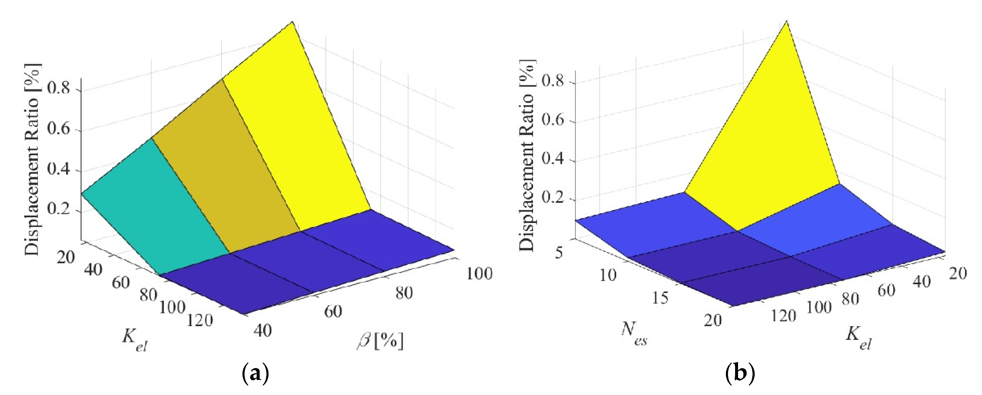
The effect of K e l on C can be seen clearly in Figure 7. The first plot sweeps K e l with β at a constant N e s = 5. Although only three K e l values are used, C shows near exponential decrease as K e l increases. The linear increase with β is shown again. The second plot sweeps K e l with N e s at a constant β = 100%. Once more, this plot shows nearly exponential decrease in C with an increase in K e l or N e s . These plots show that the torsional stiffness of the elastomeric skin is as important as the number of elastomeric sections in affecting the torsional stiffness of the hybrid composite skin. What can be achieved with high number of low-stiffness elastomeric skin sections, can also be achieved with less number of stiffer elastomeric skin sections. With a relatively stiff elastomeric skin or relatively large number of elastomeric sections, increasing the other parameter can only fine-tune the torsional compliance of the skin.

3.2. Effect of α

In this study, we keep N L = 2 and K e l = 73 N-m2. Figure 8a shows α-β sweep for N e s = 10, whereas Figure 8b shows α- N e s sweep for β = 70%. The trends at different constant values of N e s or β are almost identical to the plots in Figure 8a,b, respectively. It is very interesting to see that in the α axis, there is a dip in the structural compliance that occurs when the fiber-orientation angle of the Twistkins’ plies is 30°. This indicates that the fibers are aligned with the maximum applied stresses in this orientation and the skin is at its stiffest. On the other hand, the skin is most compliant at an α of 90°. As was shown before, when β increases, C also increases linearly, and as N e s increases, C decreases exponentially. This holds true for all values of α.
The fiber-orientation angle of the plies proved to be a very effective design parameter that can significantly affect the skin stiffness. This study changed the fiber-orientation angle of all plies together, but each angle can be controlled separately leading to a spectrum of stiffnesses to choose from for tailoring the skin stiffness to match the design requirements.

3.3. Effect of N L

In this study, α and K e l remained constant at 0° and 73 N-m2, respectively, while N L is swept, along with β in Figure 9a and N e s in Figure 9b. The trends of the N L -β and N L - N e s sweeps are the same at different values of N e s and β, respectively. Increasing the number of plies exponentially decreases C. The figures continue to show the linear increase and exponential decrease of C with an increase in β and N e s , respectively. One additional ply in the Twistkin laminate can dramatically increase the torsional stiffness of the whole skin.

4. Out-of-Plane Stiffness Study

In order to run an out-of-plane stiffness study, the aerodynamic loads experienced by the wing in flight should be considered and applied. Section 4.1 presents the CFD model that was used to obtain the applied aerodynamic loads. Section 4.2 presents the FEA models used to study the elastomeric section alone and the Twistkin alone, under aerodynamic loads. Section 4.3 and Section 4.4 show the effects of the different design parameters on the out-of-plane stiffness of the skin.

4.1. CFD Model

The twist-morphing wing is assumed to be on a UAV that cruises at 48 km/h in low altitudes. Standard sea level conditions for air were used with a density of ρ = 1.225 kg/m3, dynamic viscosity of μ = 1.7894 × 10⁻⁵ kg/m-s, ambient pressure of 101.3 kPa, and ambient temperature of 15 °C. This gives a Reynolds number of approximately Re = 215,600. These are typical flying conditions for UAVs [6]. A standard k-ε turbulence model within ANSYS Fluent was used in CFD simulations on a 2D airfoil at different angles of attack (AOAs). This is a Reynolds-Average Navier-Stokes (RANS) based model which solves the ensemble-average Navier-Stokes equations. The standard k-ε model is a commonly used turbulence model, as it is reasonably accurate and requires less computational power when compared to other models such as the realizable k-ε, standard k-ω, or SST k-ω models. The maximum lift for the NACA 0012 airfoil occurs at 12°, which was confirmed by Airfoil Tools at a similar Re of 200,000 [29]. The largest pressure load occurs at an AOA of 12°, hence the corresponding load was considered in the structural analysis. In order to use the pressure data points from the CFD study into the FEA study, rational function models were used to obtain curve fits. Figure 10 shows the pressure data on the top and bottom sides of the airfoil at an AOA of 12° along with the curve fits. The top curve fit ( P 12 T ) and the bottom curve fit ( P 12 B ) are expressed as:
P 12 T = 15.13 x L 2 4.255 x L 0.6916 x L 2 + 0.2416 x L + 0.01457 ; P 12 B = 12.05 x L 2 + 3139 x L 9471 x L 2 + 12.21 x L 26.93
where x L is the distance from the leading edge in millimeters.
This aerodynamic pressure distribution will be applied to the FEA models in the upcoming sections. The resultant displacements measured from the FEA simulations will be turned into non-dimensional displacements relative to the thickness of the airfoil. The displacement ratio is defined as the ratio of the measured displacement to half the maximum thickness of the airfoil.
D i s p l a c e m e n t R a t i o = D max 0.12 L c / 2 × 100 %
where D max is the maximum displacement. Note that smaller displacements correspond to a stiffer structure.

4.2. FEA Models

Two out-of-plane stiffness studies were performed on two different models. The first focused on the last segment of the twist-morphing skin in a twisted state. The elastomer in this state does not only experience a pressure load but is also pre-stretched. This adds a stiffness that must be accounted for. The Twistkins are assumed to twist linearly so that the angle of twist at each segment is φ s = φ max / N e s , where φ max is the maximum angle of twist, which is 12°. The fixed edge (green arrows), prescribed rotation (magenta arrows), and applied pressure (red arrows) boundary conditions can be seen in Figure 11a. The displacements were calculated at the centerline of the elastomeric section on the top surface, as this surface experiences the largest displacements. Since there are two types of “loads” applied to this segment, the displacements resulting from the application of prescribed rotation alone (called “reference displacements”) was subtracted from the total displacements with both pressure load and prescribed rotation applied. This relative displacement is then converted to a displacement ratio using Equation (8). Similar mesh convergence analysis was performed as in Figure 5b. A mesh with 7200 elements was chosen, which corresponds to an element size of 2.4 mm.
The second model, shown in Figure 11b, considers only a single CFRP Twistkin. The boundary conditions for this model include a fixed trailing edge, a partially fixed leading edge, and pressure distributions of P 12 T and P 12 B on the top and bottom surfaces, respectively. The partially fixed leading edge enables translation in the chord-wise direction, but not in the span-wise or transverse directions.
The maximum resultant displacements were recorded from the left and right edges of the top surface. These displacements were converted to displacement ratios. The reason both edges were recorded is that the Twistkin could warp if the fiber-orientation angles of the plies are not 0° or 90°. This warpage can be measured from the left and right transverse displacements. Another mesh convergence study was performed, and a mesh with 11,000 elements was selected. The element size was 1.23 mm.
Since this model only includes a single CFRP Twistkin, it was much easier to sweep the width of the strip rather than sweeping N e s and β. Recall from Equation (5) that increasing N e s and β decreases w c f .
w s = w c f L s = 1 1 + N e s ( 1 + β / 100 )
A dimensionless Twistkin width, denoted w s , that combines the effects of both N e s and β is defined and used here. An example of the total deformation of the first model, in Figure 11a, that focuses on the elastomeric section can be seen in Figure 12. The parameters used in this plot were N e s = 5, β = 100%, K e l = 16 N-m2, α = 0°, and N L = 2. The reference and total displacements recorded from the simulation can be seen in Figure 13a. Subtracting the reference displacement from the total displacement gives the “load displacement” plot, shown in Figure 13b. The maximum load displacement ratio occurs near the leading edge, which is where the greatest pressure loads are applied at a 12° angle of twist.
For the second model, shown in Figure 11b, that focuses on the CFRP laminate alone, the displacements on both sides of the CFRP Twistkins were measured. Warpage can be observed in the deformation in Figure 14a and can be clearly seen in the displacement plot in Figure 14b. The parameters here were α = 45°, N L = 2, and w s = 0.089. Warpage was found to be very minimal since the width of each Twistkin is small relative to its length.

4.3. Effects of N e s , β, and K e l on the Elastomeric Section’s Displacement Ratio

Figure 15 shows the N e s -β sweeps for various K e l values keeping α and N L constants at 0° and 2, respectively. The maximum displacement ratio seems to linearly increase with an increase in β, and this effect is enhanced as N e s decreases. On the other hand, the maximum displacement ratio decreases exponentially with an increase in N e s . The trend is similar at all values of K e l . What increases the torsional stiffness of the skin, increases also the out-of-plane stiffness. The width ratio (β) always has a linear effect on the stiffness, while N e s always has a nonlinear effect. It is interesting to see that at large values of N e s (beyond 15), variation in β has almost no effect of the out-of-plane stiffness or displacement. The effect of β is only significant at low values of N e s .
Figure 16a shows a sweep of K e l and β. A nearly exponential decrease in maximum displacement ratio can be seen with an increase in K e l . The linear variation of the maximum displacement ratio with β is also enhanced at lower K e l . Figure 16b, which is a K e l - N e s sweep, shows an exponential decrease in the maximum displacement ratio with an increase in K e l or N e s . This is very similar to what was observed in the torsional compliance study (see Figure 7b). Relatively increasing K e l or N e s would lead to a stiffer skin.

4.4. Effects of α and N L on the Twistkin’s Displacement Ratio

Figure 17a shows the effect of w s -α sweep on the displacement ratio on the left edge of the CFRP section for the case of N L = 2. The displacement ratio surface plot shows an s-curve with the variation in α, with a minimum displacement ratio at 0° and a maximum at 90°. The fiber-orientation angle of the CFRP laminate significantly alters the out-of-plane stiffness. The values at an α of 90° are approximately 17.5 times larger than the values at an α of 0°. This is different than the torsional compliance study that showed that α of 30° would lead to the stiffest skin. It is interesting to see that the effect of w s appears to change depending on the value of α. For α greater than 45°, the displacement ratio increases as w s increases. For α of 45° and under, the displacement ratio increases with a decrease in w s . This parameter ( w s ), however, has a small effect on the displacement ratio compared to α.
Figure 17b shows the effect of the N L -α sweep on the displacement ratio of the left CFRP Twistkin’s edge with w s = 0.125. Increasing N L results in an exponential decrease in the displacement ratio while α maintains the s-curve. The displacement ratio can be reduced to one-third of its value by adding a single ply; from NL = 2 to NL = 3. The same out-of-plane stiffness obtained with 5 plies of 90° fiber-orientation angle, can be obtained with only two 0° plies. The effect of α is enhanced at lower values of N L , and the effect of N L is enhanced at higher fiber-orientation angles.

5. Discussion and Conclusions

The aim of this work was to study the effect of all design parameters on the torsional and out-of-plane compliances of the twist-morphing skin in order to guide the design process and the selection of suitable actuators for this application. A good design would seek the parameters that would lead to a stiff skin in the out-of-plane or transverse direction, but with a reasonable torsional compliance that enables the available or selected actuators to twist-morph the skin. In order to be conservative, the study considered the applied aerodynamic loads at the maximum angle of twist. The study was limited to only static structural analysis, without any dynamic effects. The study also did not cover the fatigue life and temperature-dependent behavior of the elastomeric skin. In order to assume a linear behavior for the elastomer, the strains in the elastomer need to be under the threshold of 10%. The maximum strain in the most compliant skin configuration was observed to be 9.97%.
It was found that the torsional compliance of the skin can be increased by (1) increasing the width ratio (β), because this increases the elastomer-to-CFRP ratio, (2) decreasing the torsional stiffness of the elastomeric skin ( K e l ), by decreasing its thickness or choosing a material with smaller Young’s modulus, (3) using less number of plies in the Twistkin laminate ( N L ), since this reduces its stiffness, (4) decreasing the number of elastomeric sections or repeated cells in this periodic skin ( N e s ), since this will increase the width of each elastomeric section allowing for more twist or deformation, and (5) orient the plies of the Twistkin laminate away from the stiffest direction, which was found to be 30°. The sweep studies showed the rate at which these five parameters affect the torsional stiffness. β has a linear impact on C, α has a nonlinear effect, while an increase in K e l , N L , or N e s exponentially decreases C.
Under the maximum applied aerodynamic loads corresponding to the maximum twist angle of 12°, it was found that the out-of-plane stiffness can be increased by (1) decreasing β, (2) increasing K e l , (3) increasing N L , (4) increasing N e s or decreasing the dimensionless Twistkin width, w s , and (5) keeping a small fiber-orientation angle (α). Again, the effect of β was found linear, the effect of α nonlinear, and the effects of K e l , N L , or N e s were exponential. The results showed the significant effect of α and N L on the out-of-plane stiffness. The stiffness can be increased by a factor of 17.5 just by going from α = 90° to α = 0°. The stiffness can significantly increase by adding one extra ply.
Increasing the width ratio (β) or using more elastomeric sections (i.e., increasing N e s ) leads to smoother wing surface, hence reduced drag. The design process needs a careful compromise to ensure the skin is able to carry the maximum applied aerodynamic loads while still capable of twisting with the minimum possible actuation forces. One approach is to select a reasonably large number of Twistkins ( N e s = 10–15) to ensure a smooth outer surface for better aerodynamic efficiency, two plies per laminate ( N L = 2) to maintain low weight, and an elastomeric skin that has attractive properties for this application such as high toughness, long fatigue life, and low temperature expansion coefficient. The selection of the elastomeric skin will determine its torsional stiffness ( K e l ). The last two parameters, which are the width ratio (β) and the fiber-orientation angle of the laminate plies (α), can be used to fine tune the skin compliance in order to achieve the best balance between out-of-plane stiffness and torsional compliance, guided by the results of this study. β has a linear effect, while α has a nonlinear one, giving the designer more flexibility to adjust the skin design. Future work will extend the analysis to include dynamic effects and will involve manufacturing and testing of physical models.

Author Contributions

Conceptualization, P.L.B.; methodology, P.L.B. and C.A.; software, C.A.; validation, P.L.B. and C.A.; formal analysis, P.L.B. and C.A.; investigation, P.L.B. and C.A.; resources, P.L.B. data curation, C.A.; writing—original draft preparation, P.L.B. and C.A.; writing—review and editing, P.L.B.; visualization, C.A.; supervision, P.L.B.; project administration, P.L.B.; funding acquisition, P.L.B. All authors have read and agreed to the published version of the manuscript.

Funding

This research received no external funding.

Institutional Review Board Statement

Not applicable.

Informed Consent Statement

Not applicable.

Data Availability Statement

Data sharing not applicable.

Acknowledgments

The authors acknowledge the support of the Department of Mechanical Engineering at California State University, Northridge (CSUN), the Research, Scholarship and Creative Activities (RSCA) grant the first author received in 2019 from CSUN’s Research and Sponsored Programs, and CSUN’s “Thesis/Project/Dissertation Support Program” grant the second author received in 2020.

Conflicts of Interest

The authors declare no conflict of interest.

References

  1. Vey, S.; Paschereit, O.; Greenblatt, D.; Meyer, R. Flap Vortex Management by Active Gurney Flaps. In Proceedings of the 46th AIAA Aerospace Sciences Meeting and Exhibit, Reno, NV, USA, 7–10 January 2008. [Google Scholar]
  2. De Breuker, R.; Werter, N. On the importance of morphing deformation scheduling for actuation force and energy. Aerospace 2016, 3, 41. [Google Scholar] [CrossRef] [Green Version]
  3. Sofla, A.; Meguid, S.; Tan, K.; Yeo, W. Shape morphing of aircraft wing: Status and challenges. Mater. Des. 2010, 31, 1284–1292. [Google Scholar] [CrossRef]
  4. Bishay, P.L.; Burg, E.; Akinwunmi, A.; Phan, R.; Sepulveda, K. Development of a new span-morphing wing core design. Designs 2019, 3, 12. [Google Scholar] [CrossRef] [Green Version]
  5. Bishay, P.L.; Finden, R.; Recinos, S.; Alas, C.; Lopez, E.; Aslanpour, D.; Flores, D.; Gonzalez, E. Development of an SMA-based camber morphing UAV tail core design. Smart Mater. Struct. 2019, 28, 075024. [Google Scholar] [CrossRef]
  6. Schlup, A.E.; MacLennan, T.L.; Barajas, C.; Talebian, B.L.; Thatcher, G.C.; Flores, R.B.; Perez-Norwood, J.D.; Torres, C.L.; Kibret, K.B.; Guzman, E.; et al. MataMorph 2: A New Experimental UAV with Twist-Morphing Wings and Camber- Morphing Tail Stabilizers. In Proceedings of the AIAA Scitech 2021 Forum, Virtual Event, 11–15 & 19–21 January 2021. [Google Scholar]
  7. Rea, F.; Amoroso, F.; Pecora, R.; Moens, F. Exploitation of a multifunctional twistable wing trailing-edge for performance improvement of a turboprop 90-seats regional aircraft. Aerospace 2018, 5, 122. [Google Scholar] [CrossRef] [Green Version]
  8. Joshi, S.P.; Tidwell, Z.; Crossley, W.A.; Ramakrishnan, S. Comparison of Morphing Wing Strategies Based Upon Aircraft Performance Impacts. In Proceedings of the 45th AIAA/ASME/ASCE/AHS/ASC Structures, Structural Dynamics & Materials Conference, Palm Springs, CA, USA, 19–22 April 2004. [Google Scholar]
  9. Beaverstock, C.S.; Woods, B.K.S.; Fincham, J.H.S.-M.; Friswell, M.I. Performance comparison between optimised camber and span for a morphing wing. Aerospace 2015, 2, 524–554. [Google Scholar] [CrossRef] [Green Version]
  10. Smithsonian National Air and space Museum “The Wright Brothers: Construction and Fabric”. Available online: https://airandspace.si.edu/exhibitions/wright-brothers/online/fly/1903/construction.cfm (accessed on 10 June 2021).
  11. Barbarino, S.; Bilgen, O.; Ajaj, R.M.; Friswell, M.I.; Inman, D. A review of morphing aircraft. J. Intell. Mater. Syst. Struct. 2011, 22, 823–877. [Google Scholar] [CrossRef]
  12. Rodrigue, H.; Cho, S.; Han, M.; Bhandari, B.; Shim, J.; Ahn, S. Effect of twist morphing wing segment on aerodynamic performance of UAV. J. Mech. Sci. Technol. 2016, 30, 229–236. [Google Scholar] [CrossRef]
  13. Gern, F.H.; Inman, D.J.; Kapania, R.K. Structural and aeroelastic modeling of general planform wings with morphing airfoils. AIAA J. 2002, 40, 628–637. [Google Scholar] [CrossRef]
  14. Olympio, K.R.; Gandhi, F. Flexible skins for morphing aircraft using cellular honeycomb cores. J. Intell. Mater. Syst. Struct. 2009, 21, 1719–1735. [Google Scholar] [CrossRef]
  15. Bubert, E.A.; Woods, B.K.; Lee, K.; Kothera, C.S.; Wereley, N.M. Design and fabrication of a passive 1D morphing aircraft skin. J. Intell. Mater. Syst. Struct. 2010, 21, 1699–1717. [Google Scholar] [CrossRef]
  16. Jenett, B.; Calisch, S.; Cellucci, D.; Cramer, N.; Gershenfeld, N.; Swei, S.; Cheung, K.C. Digital morphing wing: Active wing shaping concept using composite lattice-based cellular structures. Soft Robot. 2017, 4, 33–48. [Google Scholar] [CrossRef] [Green Version]
  17. Mistry, M.; Gandhi, F.; Nagelsmit, M.; Gurdal, Z. Actuation requirements of a warp-induced variable twist rotor blade. J. Intell. Mater. Syst. Struct. 2011, 22, 919–933. [Google Scholar] [CrossRef]
  18. Vos, R.; Gürdal, Z.; Abdalla, M. Mechanism for warp-controlled twist of a morphing wing. J. Aircr. 2010, 47, 450–457. [Google Scholar] [CrossRef]
  19. Alsaidi, B.; Joe, W.Y.; Akbar, M. Simplified 2D skin lattice models for multi-axial camber morphing wing aircraft. Aerospace 2019, 6, 90. [Google Scholar] [CrossRef] [Green Version]
  20. Alsaidi, B.; Joe, W.Y.; Akbar, M. Computational analysis of 3D lattice structures for skin in real-scale camber morphing aircraft. Aerospace 2019, 6, 79. [Google Scholar] [CrossRef] [Green Version]
  21. Arena, M.; Nagel, C.; Pecora, R.; Schorsch, O.; Concilio, A.; Dimino, I. Static and dynamic performance of a morphing trailing edge concept with high-damping elastomeric skin. Aerospace 2019, 6, 22. [Google Scholar] [CrossRef] [Green Version]
  22. Guiler, R.; Huebsch, W. Wind Tunnel Analysis of a Morphing Swept Wing Tailless Aircraft. In Proceedings of the 23rd AIAA Applied Aerodynamics Conference, Toronto, ON, Canada, 6–9 June 2005. [Google Scholar] [CrossRef]
  23. Garcia, H.; Abdulrahim, M.; Lind, R. Roll Control for a Micro Air Vehicle Using Active Wing Morphing. In Proceedings of the AIAA Guidance, Navigation, and Control Conference and Exhibit, Austin, TX, USA, 11–14 August 2003. [Google Scholar] [CrossRef] [Green Version]
  24. Stanford, B.; Abdulrahim, M.; Lind, R.; Ifju, P. Investigation of membrane actuation for roll control of a micro air vehicle. J. Aircr. 2007, 44, 741–749. [Google Scholar] [CrossRef] [Green Version]
  25. Barrett, R. Active aeroelastic tailoring of an adaptive Flexspar stabilator. Smart Mater. Struct. 1996, 5, 723–730. [Google Scholar] [CrossRef]
  26. Elzey, D.M.; Sofla, A.Y.N.; Wadley, H.N.G. A bio-inspired high-authority actuator for shape morphing structures. In Proceedings of the Smart Structures and Materials 2003: Active Materials: Behavior and Mechanics, San Diego, CA, USA, 13 August 2003. [Google Scholar]
  27. Bartley-Cho, J.D.; Wang, D.P.; Martin, C.A.; Kudva, J.N.; West, M.N. Development of high-rate, adaptive trailing edge control surface for the smart wing phase 2 wind tunnel model. J. Intell. Mater. Syst. Struct. 2004, 15, 279–291. [Google Scholar] [CrossRef]
  28. Raither, W.; Heymanns, M.; Bergamini, A.; Ermanni, P. Morphing wing structure with controllable twist based on adaptive bending–twist coupling. Smart Mater. Struct. 2013, 22, 65017. [Google Scholar] [CrossRef]
  29. Airfoil Tools “NACA 0012 Airfoils”. Available online: http://airfoiltools.com/airfoil/details?airfoil=n0012-il (accessed on 8 January 2021).
Figure 1. (a) Model of a UAV with a twist-morphing wing, (b) Dimensions of the twisting section featuring CFRP “Twistkins” (grey) and elastomeric sections (blue).
Aerospace 08 00259 g001
Figure 2. Profile of a single Twistkin.
Aerospace 08 00259 g002
Figure 3. Twisting section without the flexible sections at (a) φ = 0° and (b) φ = 12°. First Twistkin (blue) is attached to the fixed section while the last Twistkin (red) is attached to the rotating spar (red).
Aerospace 08 00259 g003
Figure 4. Different model configurations with (a) N e s = 5 and β = 40%, (b) N e s = 5 and β = 100%, (c) N e s = 15 and β = 40%, and (d) N e s = 15 and β = 100%.
Aerospace 08 00259 g004
Figure 5. (a) Torsional compliance study model with two CFRP Twistkins and one elastomeric section, (b) Mesh convergence plot.
Aerospace 08 00259 g005
Figure 6. Torsional compliance sweeping N e s and β for (a) K e l = 16 N-m2, (b) K e l = 73 N-m2, (c) K e l = 134 N-m2.
Aerospace 08 00259 g006
Figure 7. Torsional compliance sweeping (a) K e l and β for N e s = 5, (b) K e l and N e s for β = 100%.
Aerospace 08 00259 g007
Figure 8. Torsional compliance sweeping (a) α and β for N e s = 10, (b) α and N e s for β = 70°.
Aerospace 08 00259 g008
Figure 9. Torsional compliance sweeping (a) N L and β for N e s = 10, (b) N L and N e s for β = 70%.
Aerospace 08 00259 g009
Figure 10. Pressure distribution from 2D CFD study at an AOA of 12°.
Aerospace 08 00259 g010
Figure 11. Out-of-plane stiffness model with (a) two Twistkins (grey) and one elastomeric section (blue) at loads corresponding to φ = 12°. (b) one Twistkin.
Aerospace 08 00259 g011
Figure 12. Example of total displacement ( N e s = 5, β = 100%, K e l = 16 N-m2, α = 0°, and N L = 2).
Aerospace 08 00259 g012
Figure 13. Example of (a) reference and total displacements (b) load displacement.
Aerospace 08 00259 g013
Figure 14. (a) Total displacement of CFRP Twistkin, (b) Displacement ratio at both edges of the CFRP Twistkin.
Aerospace 08 00259 g014
Figure 15. Maximum displacement ratio for the elastomeric section sweeping N e s and β for (a) K e l = 16 N-m2, (b) K e l = 73 N-m2, (c) K e l = 134 N-m2.
Aerospace 08 00259 g015
Figure 16. Maximum displacement ratio for the elastomeric section sweeping (a) K e l and β for N e s = 5, (b) K e l and N e s for β = 100%.
Aerospace 08 00259 g016
Figure 17. Displacement ratios sweeping (a) w s and α, (b) N L and α, for the left edge.
Aerospace 08 00259 g017
Publisher’s Note: MDPI stays neutral with regard to jurisdictional claims in published maps and institutional affiliations.

