1. Introduction
Cathodes have been used as electron sources in electric propulsion systems of spacecraft and satellites [
1,
2,
3]. Cathodes are essential components of the two most commonly used plasma thruster types, Hall thrusters and ion engines. As Hall thrusters and ion engines eject positively charged ion beams, an electron source is needed for the neutralization of the ion beam to avoid spacecraft charging. Cathodes are also used for the ionization of the propellant [
4]. Hollow cathodes are the most common type of cathodes used in electric propulsion systems. The operation of hollow cathodes is based on thermionic emission mechanism. Insert materials with low work function are utilized as electron emitters that provide electrons at high temperatures through thermionic emission. Electrons emitted from the insert collide with the propellant gas that is injected into the cathode tube and generate a plasma inside the cathode tube (
Figure 1). Electrons are extracted from this plasma with an external positive electric potential applied using an electrode. Plasma inside the cathode tube is maintained by the electron emission and steady propellant flow. The emission current density of the emitter material is dependent on the work function of the material and temperature [
5].
Commonly used emitter materials are barium-oxide impregnated tungsten (
) and lanthanum hexaboride (
).
has a very low work function of 2.06 eV [
2,
6]. Low work function of
enables operation at about 1100 °C. However,
is highly sensitive to impurities in the propellant and exposure to atmosphere. Poisoning of the emitter material because of impurities increases work function and leads to cathode failure or shortened lifetime [
6,
7].
is an alternative emitter with a higher work function of 2.67 eV [
2,
6,
8,
9,
10,
11,
12]. Higher temperatures, about 1500 °C, are needed for
inserts [
13,
14]. However,
emitters are much less sensitive to impurities in propellant gas and do not need special conditioning procedures, and have a longer lifetime [
6,
11,
15,
16].
High temperature at the emitter material is achieved with the use of a heater element. When the emitter temperature is increased to required levels, electrons emitted from the emitter collide with the neutral particles in the propellant and generate a quasi-neutral plasma inside the cathode tube. A sheath formation occurs at the emitter surface as electrons are extracted from the surface [
17]. The electric field of the sheath accelerates the ions towards the emitter surface. Collision of the ions with the emitter surface provides a self heating mechanism [
2,
18,
19]. The self heating mechanism adjusts the insert surface temperature according to the extracted electron current and sustains a plasma inside the cathode tube [
20]. After the self heating mechanism is initiated, external heater power is not needed anymore and heater power can be turned off. As high temperatures are needed for thermionic emission, materials that can withstand very high temperatures are used in hollow cathodes. Thermal design of the hollow cathodes is crucial for its operational characteristics and lifetime, as heat losses determine the required power level of the heater element for the initiation of the cathode operation as well as sustaining the operation [
21,
22,
23,
24,
25].
In this study, thermal analyses and experimental results for several different hollow cathodes, with different heater designs that are developed at Bogazici University Space Technologies Laboratory (BUSTLab), are presented. Based on the conducted tests, possible hot spots and weak points are determined, and improvements to the designs are made. In all these cathode designs, a tube with 2 mm inner diameter, 4 mm outer diameter and 10 mm length is used as the emitter material.
2. Studied Hollow Cathode Designs
In a typical hollow cathode, the emitter insert material is placed inside a hollow cylinder, called a cathode tube, which is made of a conductive material such as graphite or molybdenum that can withstand high temperatures. The insert material is heated by a resistive heater. For this purpose, a heater coil is wrapped around the cathode tube. As the heater material, refractory metals such as tungsten, tantalum, molybdenum or rhenium could be used. The cathode tube is attached to a base plate with a ceramic holder. Finally, the cathode tube is enclosed within a keeper tube, which protects the cathode assembly and is used to initiate cathode operation by applying an external electrical potential. The keeper tube is made of a high temperature conductor, such as graphite or molybdenum, and mounted on a ceramic base. Between the cathode tube and the keeper, several radiation shields are utilized for thermal insulation. Heater element design is one of the most critical parts of the cathode design, as heater failure is the foremost failure mode of cathode operation.
2.1. First Conventional Hollow Cathode Design
In the first design, shown in
Figure 2a, the heater element consists of tantalum wire with 0.25 mm diameter and double bore alumina tubes. The resistive wire is sewn into the holes of the alumina tubes. A tantalum cover is placed around the heater for radiative shielding. A macor ceramic part supports the heater element. The electrical connection of the resistive element is supplied with thicker tantalum wires that is insulated with alumina tubes and spine beads. During the tests, it was seen that the turning points of heater wire that is outside of the insulator alumina tubes cause hot spots and weak points, which lead to cathode failure as shown in
Figure 3a. Unequal thermal contact with the insulation generates temperature variance and causes hot sections in the heater wire. It was also seen that elevated temperatures at the bending regions result in damage to the thin alumina tubes. According to the test results, it was understood that the heater wire has to be in thermal contact with an insulator material at all points to avoid hot spots, and any sharp turns have to be avoided.
2.2. Second Conventional Hollow Cathode Design
In the second design, shown in
Figure 2b, the heater wire is wrapped around the helical grooves of a high temperature insulator material, in this case shapal. The electrical connection of the upper end of the wire is achieved through a contact with the cathode tube, which provides the ground voltage to the heater electrical circuit. The bottom end of the wire is connected to a thicker tantalum wire that is insulated with alumina tubes and spine beads. The heater wire is kept within the grooves of the shapal heater part using an external hollow insulating cylindrical cap, which secures the heater wire at the grooves. This heater design proved to be a more robust design. However, electrical connections of the heater wire generates hot spots after the helical grooves region that result in failure due to the breakage of the heater wire as a result of excessive local heating as shown in
Figure 3b.
2.3. Coaxial-Heater Hollow Cathode Design
Based on the problems that are encountered with the conventional heater designs, a cathode with a coaxial–heater is designed, which is shown in
Figure 4 [
26]. In this design, any sharp turns of the heater wire are avoided, hence minimizing the possibility of weak points in the heater circuit. The electrical connection of the heater wire at the bottom end is provided through a coaxial graphite part. The heater wire is wrapped around the grooves of the shapal insulator at the insert region and then wrapping is continued around the grooves of the graphite part. The grooves of the shapal and graphite parts are aligned for smooth transition. This coaxial graphite part is insulated from the cathode tube with a thin walled alumina tube. The heater wire is secured in its grooves with a shapal cover part. This shapal insulator cap compresses the wire to the grooves and sustains good thermal contact at every point. As the heater wire is insulated completely, a more uniform temperature profile is achieved, which extends cathode lifetime.
As no sharp turns exist along the wire, critical weak points are avoided. Tests proved that the coaxial–heater design significantly improves cathode lifetime and increases the number of cathode initializations without failure. However, such a design also increases the conduction heat losses from the heater region of the cathode to the base plate due to the presence of the coaxial graphite part in addition to the graphite cathode tube.
3. Thermal Analyses of Different Cathode Designs
Thermal characteristics of hollow cathode heater designs are investigated numerically using COMSOL Multiphysics [
27]. For the analyses, 2D axisymmetric computational domains with about 14,000 mesh cells are used. The analyses are performed for the steady state case during the cathode operation. In each case, the inner surface of the
insert is kept at 1500 °C, which is sustained by the self-heating mechanism of the cathode plasma. Heat transfer from the insert region plasma is important in determining the power needed for sustaining the self heating mechanism [
19]. In order to simulate the interaction of the cathode with the support structure, the bottom surface of the cathode base part is kept at 400 °C. As the cathode operates in a high vacuum environment, convective heat transfer is neglected. Heat energy obtained from the self-heating mechanism is transferred within the cathode structure with conductive and radiative heat transfers. Besides the conductive heat loss from the cathode base, the outer surfaces of the cathode lose heat to the ambient via radiative heat transfer. During the analysis, surface emissivity and thermal conductivity values of the cathode materials vary with temperature [
8,
15].
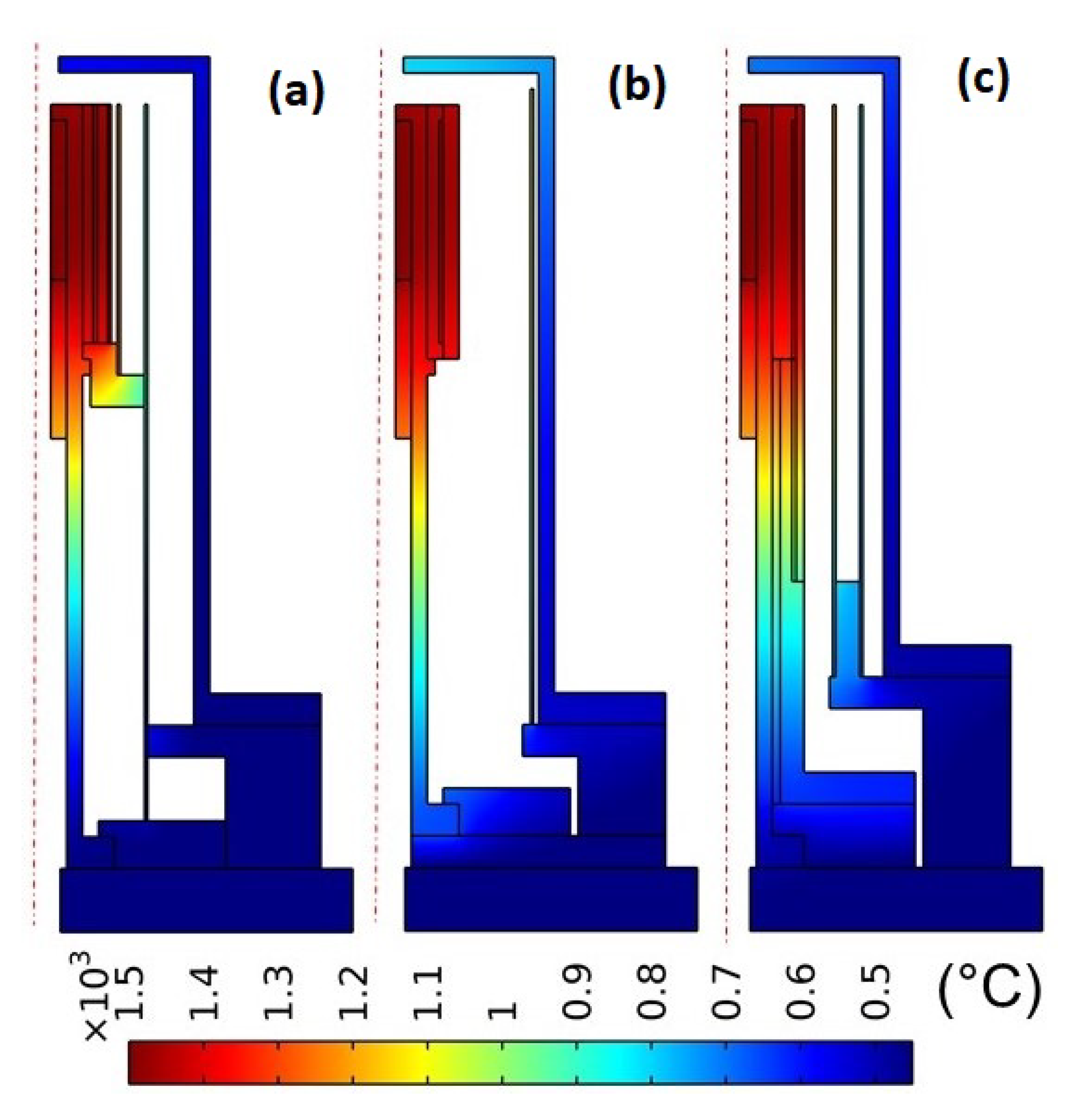
The temperature distributions within the cathode structure for the three different heater designs are shown in
Figure 5. In these figures, dashed red lines show the centerline of the cross section for each cathode. As part of the analysis, the heat input to the inner surface of the
insert is determined and the heat loss to the cathode base via conductive heat transfer is investigated. In the first conventional heater configuration, 79 W heat needs to be deposited to the insert, while 15 W heat is lost to the base part. However, for the second conventional heater configuration, in order to keep the insert inner surface temperature constant at 1500 °C, the heat deposition must be increased to 143 W, with 16 W heat loss to the base. For the coaxial heater design, the required heat deposition is 148 W, and the heat loss to the base increases to 34 W.
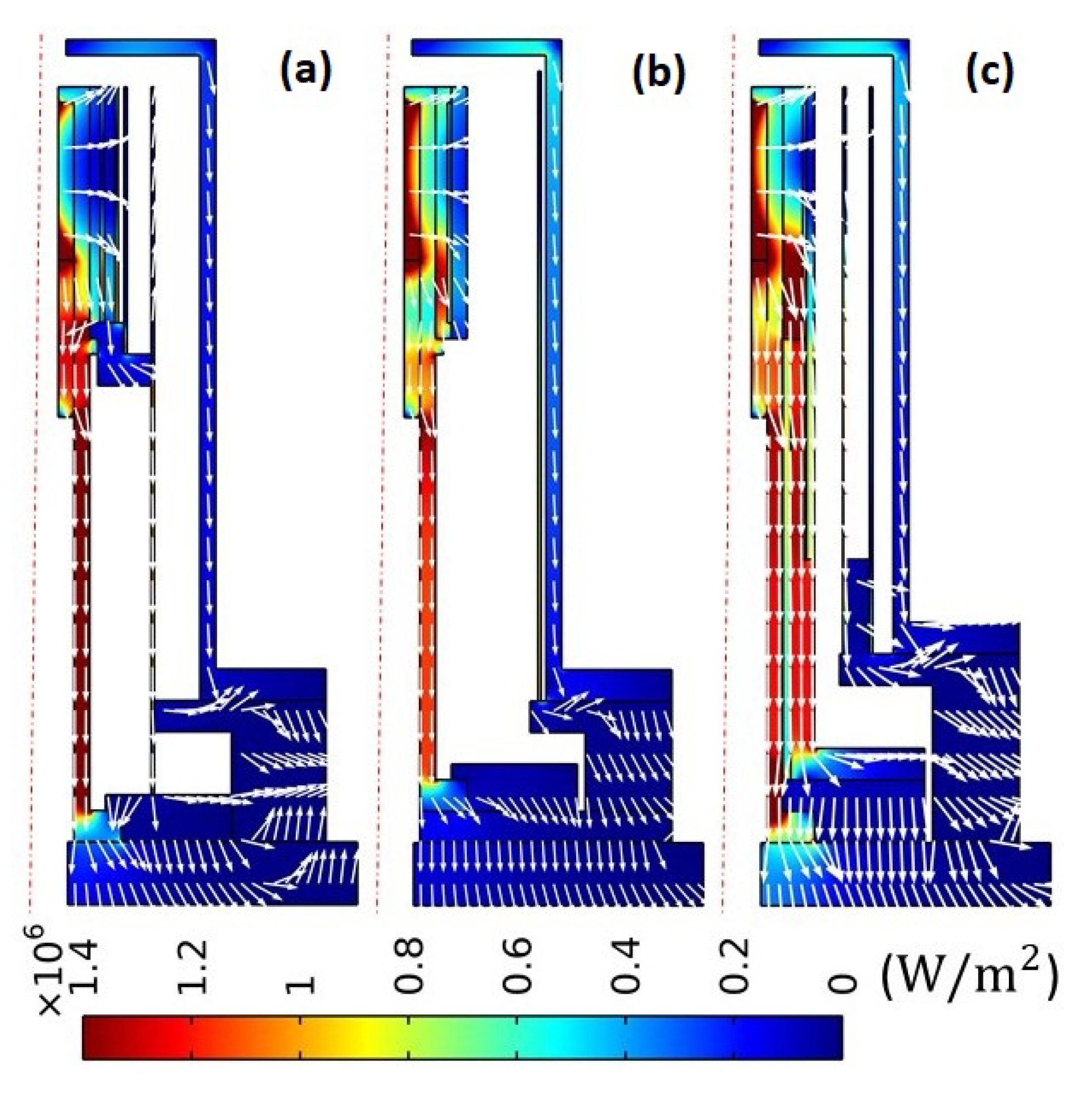
Thermal characteristics of the different designs can be better investigated when the heat flux distributions are compared as shown in
Figure 6. In this figure, the conductive heat transfer paths are shown with white arrows. With a higher conductive heat transfer rate, the graphite cathode tube is the main thermal path for the heat loss to the cathode base. The cross section of the graphite parts is greater for the coaxial–heater design. However, since the additional outer graphite part is mounted on a macor ceramic insulator, heat flux to the base plate dramatically decreased. In the second conventional and coaxial–heater designs, the heater coil is wrapped around an electrically insulating but thermally conductive ceramic shapal part. High thermal conductivity of the shapal part decreases the heater power needed during ignition. However, after the ignition of the cathode plasma, the shapal part provides a heat loss path from the insert. Despite higher heat loss values, the grooved shapal part is advantageous due to its good machinability and low electrical conductivity at high temperatures. Based on the thermal analysis results of the coaxial–heater design, it is seen that in order to reduce heat losses, the cathode tube should be thermally insulated from the cathode base structure with ceramic insulators.
In all three configurations, it is observed that the main heat loss mechanism from the cathode is the radiative heat transfer from the outer surface of the keeper. Therefore, it is essential to use radiative shields around the heater. The effectiveness of the radiative shields can be seen when the results of the first and second conventional heater designs are compared. In the first conventional heater design, two concentric shields are utilized; however, in the second heater design, a single shield is used. It is observed that the heat loss to the keeper is much higher for the second configuration and, as a result, a higher temperature is observed at the keeper surface. For the coaxial–heater design, similar to the first conventional heater design case, two concentric shields are utilized. It is observed that in the coaxial design configuration, the heat loss decreased with respect to the second conventional design even though the cross section of the conductive part from the heater to the base increased.
3.1. Comparison of Different Coaxial-Heater Cathode Configurations
Since the radiative insulation is essential for reducing the thermal losses of hollow cathodes, further thermal analyses are conducted with different radiative shield configurations for the coaxial–heater design. In
Figure 7, surface radiosity values for the inner surfaces around the heater element are shown for three different radiation shield configurations. More heat is radiated away from red surfaces, which have higher surface emissivity and temperature.
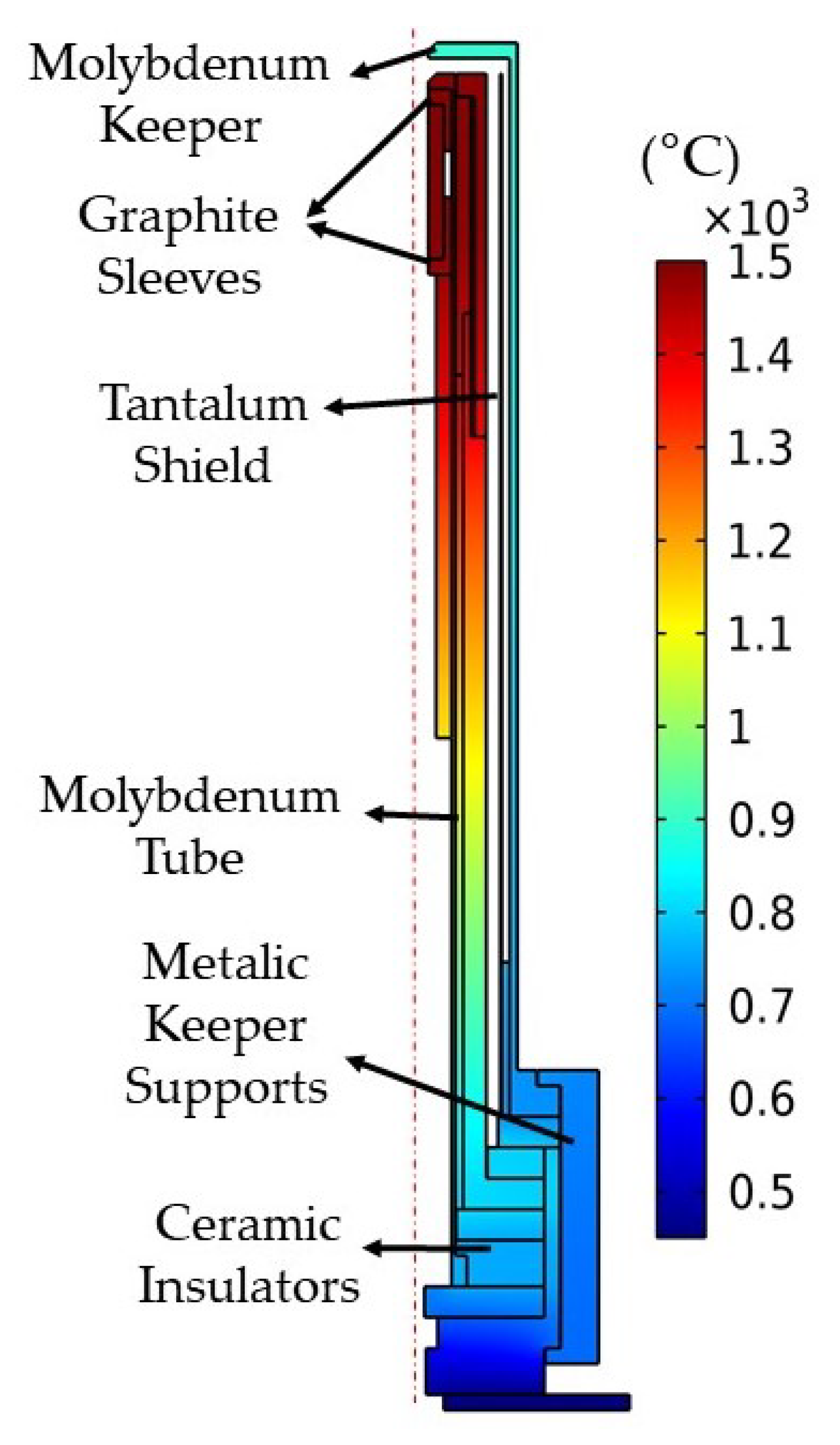
In
Figure 7, the first configuration is the coaxial–heater design with two tantalum radiative shields. In this design, 148 W heater power has to be deposited for cathode operation. In the second configuration, molybdenum is utilized instead of graphite as the keeper and cathode tube material. Direct contact of the refractory metals with
may cause the embrittlement of the high temperature refractory metals because of boron diffusion [
6]. Therefore, for this design, the
insert is supported inside the molybdenum cathode tube with thin graphite sleeves. Since molybdenum has much lower surface emissivity, heat loss from the keeper surface decreased dramatically. The total heater power input decreased to 125 W. Utilization of molybdenum as the cathode tube material provides several benefits. It was seen during the tests that electrical contact between the tantalum heater wire and graphite tube causes a weak point that leads to cathode failure. Utilizing molybdenum as the cathode tube material instead of graphite allows the welding of the electrical contact point and eliminates this weak point. Molybdenum tube is also less brittle compared to the graphite tube; therefore, molybdenum tubes can be machined with thinner walls.
Since the ceramic insulator cover of the heater element has high surface emissivity, significant heat loss occurs from the surface of the heater element. Therefore, in the third configuration, a molybdenum cap is placed around the insulator cover of the heater. Covering the ceramic insulator with a low surface emissivity material further decreases the required heater power input to 108 W.
3.2. Comparison of Coaxial-Heater Configurations with Different Cathode Tube Lengths
The utilization of molybdenum as the cathode tube material has its advantages. However, the high thermal conductivity of molybdenum causes a thermal pathway from the heater region to the cathode base. In order to investigate the effect of the thermal pathway caused by the cathode tube, an analysis is conducted for different lengths of the cathode tube, hence the entire cathode. Shorter and longer versions of the coaxial–heater cathode design, presented in
Figure 7b, are analysed. In both designs, the molybdenum cathode and keeper tubes are utilized. The shorter design is 25% shorter, while the longer design is 60% longer than that in
Figure 7b. In
Figure 8, the temperature distributions for cathode tubes with different lengths are shown. It was seen that the heater power input increases to 200 W for the shorter design, because of the shorter thermal pathway to the cathode base. However, a 60% increment in cathode tube length decreases the heating power to 92 W from the mid-size cathode design’s heating power value of 125 W, by decreasing the heat loss to the cathode base.
3.3. Novel Coaxial-Heater Cathode Configuration
Based on the thermal analysis results, a novel hollow cathode, the design of which is based on the coaxial–heater design, is constructed as shown in
Figure 9. In this design, molybdenum is used as the cathode tube and keeper material. A longer cathode tube is utilized. The keeper is mounted on metal supports made of molybdenum. By using materials with low emissivity values for the keeper holder, low emissivity values are achieved at all surfaces of the cathode that radiates heat to the ambient. Thus, the radiative heat loss decreased considerably. Electrical connection to the keeper is provided through these metal supports. The keeper supports, cathode tube and heater structure are insulated from the cathode base with additional ceramic insulators. Electrical connections to the heater and the cathode tube are achieved through holes in the ceramic insulators. At the upper end, the tantalum heater wire is welded to the molybdenum cathode tube, thus the risk of failure at the electrical connection of the heater wire and the cathode tube is greatly decreased. The temperature distribution of this novel cathode design is analyzed as shown in
Figure 10. For this design, only 55 W of heat deposition is necessary for steady cathode operation. The utilization of the ceramic insulators at the base region reduces the heat loss to the support structure to 8 W. Required heater power inputs for different cathode configurations are listed in
Table 1.
4. Cathode Performance Tests
The hollow cathodes, the designs of which are discussed in this study, are tested extensively, and possible failure modes and operational characteristics are investigated. These tests are conducted inside the vacuum chamber of BUSTLab [
28] which is 1.5 m in diameter and 2.7 m in length. During the tests, pressure inside the vacuum chamber is kept at
torr levels. The cathodes are turned on and off dozens of times. The developed cathodes are used with thrusters developed at BUSTLab, such as the HK40 Hall thruster and the UK90 Hall thruster [
29,
30,
31,
32]. Argon is used as the propellant during the tests.
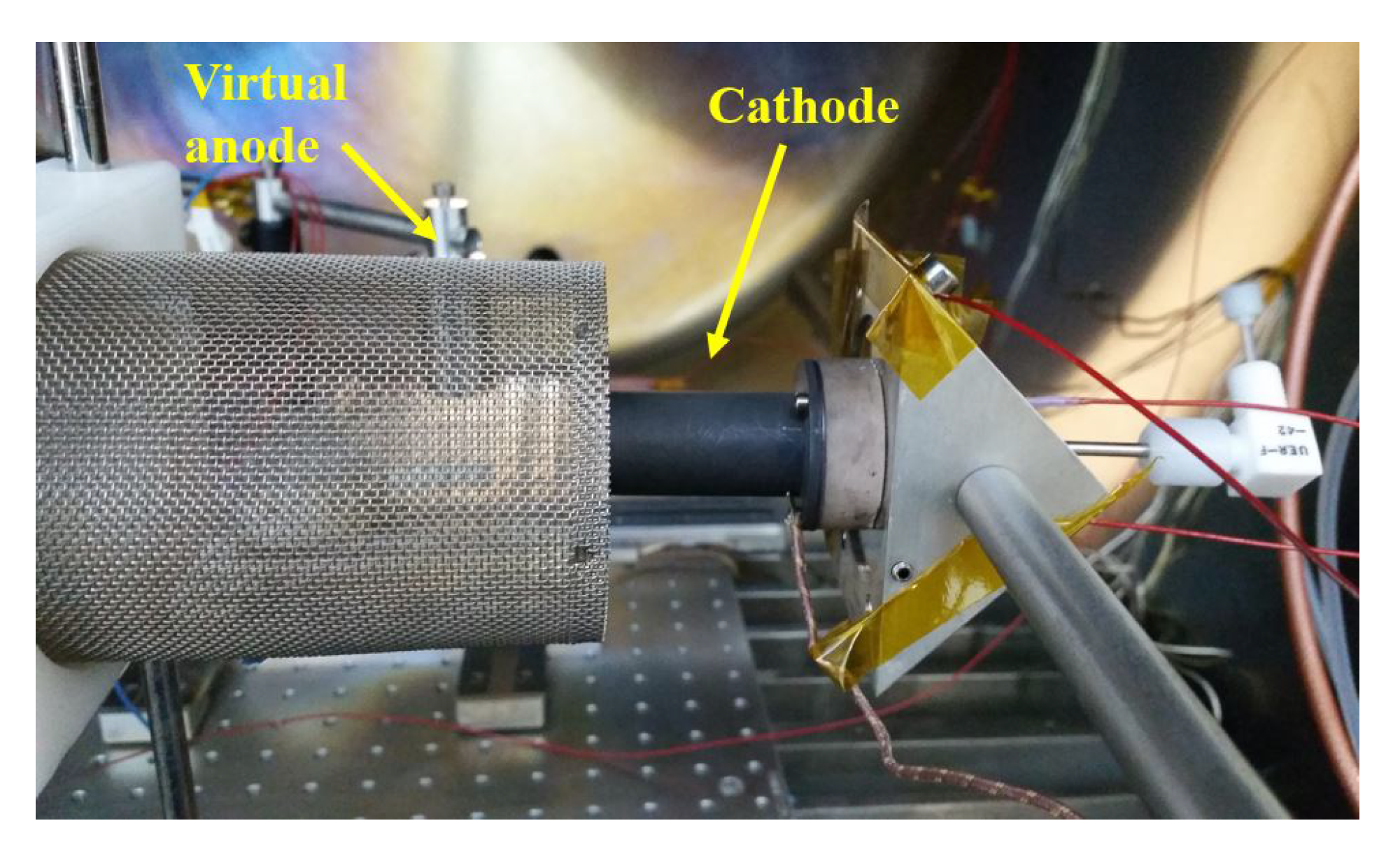
During the hollow cathode tests, a virtual anode is used as shown in
Figure 11. The virtual anode is a cylinder made of perforated steel, which mimics the plume plasma of the thruster and completes the discharge electrical circuit. A floating electrical setup is utilized with three power sources. All power sources are connected to a floating common ground: a positive voltage is applied to the virtual anode, and discharge current and discharge voltage are measured using this power source. Two other power sources are used as the heater and keeper supplies.
The cathode tests are initiated by the cathode heating process, which takes several minutes. The cathode is gradually heated to the required temperature [
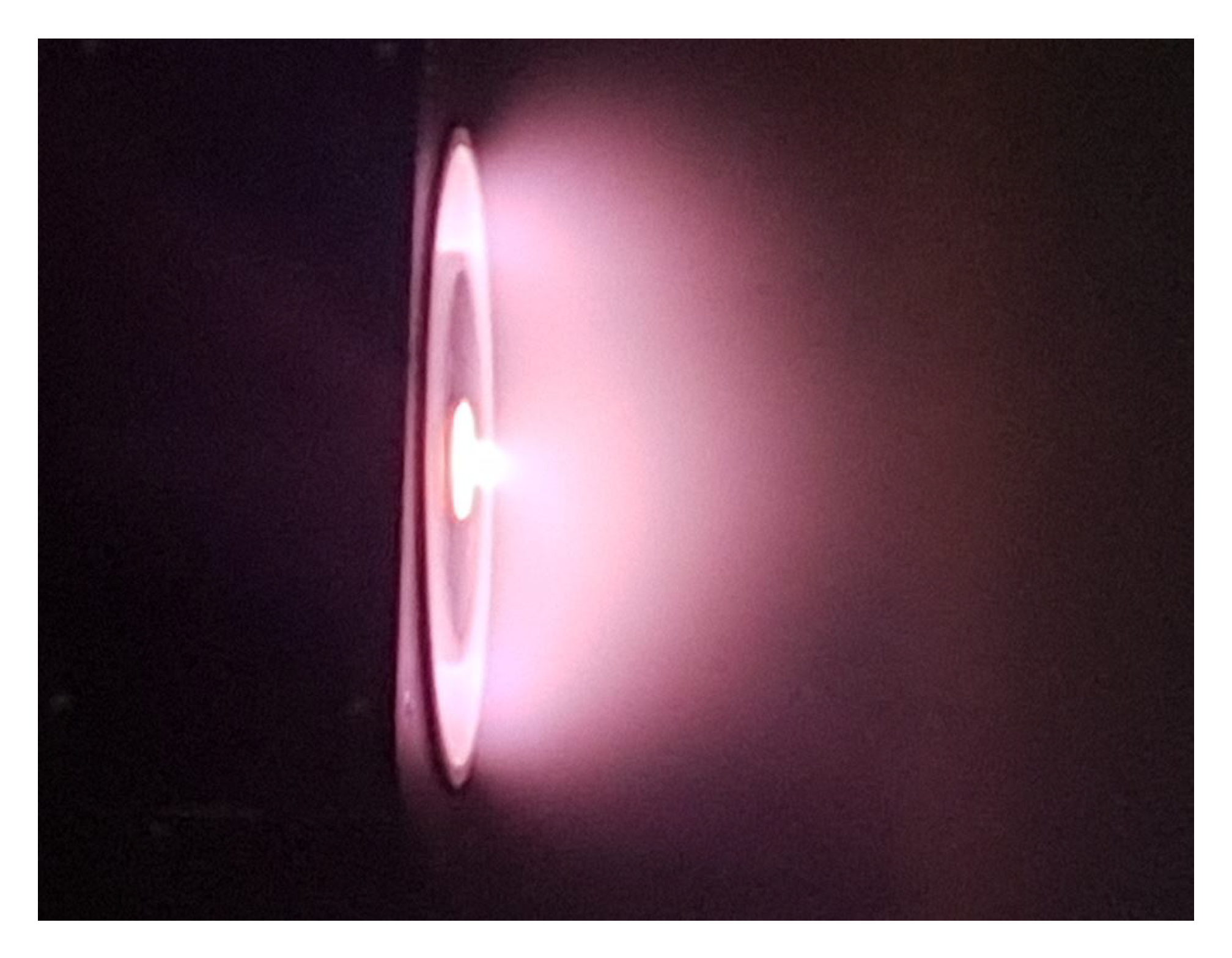
25]. During the heating process, propellant is fed to the cathode tube and a high voltage of around 300–400 V is applied to the keeper. As the cathode discharge begins, the keeper voltage drops to 25–35 V with a keeper current of 1 A. Besides, it is observed that sometimes a sudden purge of gas also helps with the initiation of the electron emission. After the stable cathode operation is achieved, thermionic emission can be carried out with the self-heating mechanism, which is supported by the keeper voltage, thus the heater power can be turned off. The cathode operation with the coaxial–heater configuration is shown in
Figure 12.
Repeatable and reliable operation is achieved with the novel coaxial hollow cathode design. For the novel coaxial cathode, the discharge voltage that is applied to the virtual anode is recorded for different mass flow rates and discharge current levels. The I–V characteristics of the current collected by the virtual anode versus the potential applied to the virtual anode for different mass flow rates are shown in
Figure 13. With the novel coaxial–heater configuration, the keeper power supply can be turned off for discharge currents above 4 A. The test results show that stable cathode operation can be achieved for discharge currents between 0.5–12 A, which is suitable for a wide range of thruster operation. In
Figure 14, the hollow cathode is shown during the tests of the UK90 Hall thruster that is developed at the BUSTLab. The UK90 Hall thruster operates at 1500 W discharge power level and has a center-mounted cathode configuration. It was seen that the developed cathode operates successfully with mid-power level thrusters in a center-mounted configuration [
33].
5. Conclusions
Thermal analysis results of several hollow cathodes with different designs are presented. The analysis results show how certain design variations and materials used affect the heat losses and failure modes. Aside from the numerical simulation work, operational characteristics of the developed cathodes have been experimentally investigated. Based on these simulations and experimental tests, a more robust hollow cathode design with a longer lifetime is built. In this design, the use of a longer molybdenum cathode tube, a coaxial graphite electrical connection for the heater wire, low emissivity materials on the outer surfaces, and welding of the heater wire to the cathode tube, proved to be a sturdier design. With this novel design, we achieved a cathode with a total heater power input of only 55 W that can operate stably at discharge currents in the 0.5 A to 12 A range. With a discharge current level as low as 0.5 A, this cathode can be used for small satellite propulsion systems. At the same time, due to its stable operation at much higher current levels, such as 12 A, this cathode can also be used with mid-power level thrusters.
Author Contributions
Conceptualization, U.K. and N.T.; methodology, U.K. and N.T.; formal analysis, U.K.; writing—original draft preparation, M.C. and U.K.; writing—review and editing, U.K., N.T. and M.C.; supervision, M.C.; funding acquisition, M.C. All authors have read and agreed to the published version of the manuscript.
Funding
This research is funded by Turkish Scientific and Technological Research Council (TUBITAK) under project number 214M572.
Acknowledgments
The authors would like to thank Huseyin Kurt of Istanbul Medeniyet University for his contributions to this study. Kurt personally machined most of the parts of the cathodes tested in this study, in addition he assembled most of the cathode parts studied in this work.
Conflicts of Interest
The authors declare no conflict of interest.
References
- Martinez-Sanchez, M.; Pollard, J.E. Spacecraft Electric Propulsion - An Overview. J. Propuls. Power 1998, 14, 688–699. [Google Scholar] [CrossRef] [Green Version]
- Goebel, D.M.; Katz, I. Fundamentals of Electric Propulsion: Ion and Hall Thrusters; JPL Space Science and Technology Series: New York, NY, USA, 2008. [Google Scholar]
- Dale, E.; Jorns, B.; Gallimore, A. Future Directions for Electric Propulsion Research. Aerospace 2020, 7, 120. [Google Scholar] [CrossRef]
- Levchenko, I.; Bazaka, K.; Ding, Y.; Raitses, Y.; Mazouffre, S.; Henning, T.; Klar, P.; Shinohara, S.; Schein, J.; Garrigues, L.; et al. Space Micropropulsion Systems for Cubesats and Small Satellites: From Proximate Targets to Furthermost Frontiers. Appl. Phys. Rev. 2018, 5, 011104. [Google Scholar] [CrossRef]
- Gao, J.Y.; Yang, Y.F.; Zhang, X.K.; Li, S.L.; Hu, P.; Wang, J.S. A Review on Recent Progress of Thermionic Cathode. Tungsten 2020, 2, 289–300. [Google Scholar] [CrossRef]
- Goebel, D.M.; Watkins, R.M. Compact Lanthanum Hexaboride Hollow Cathode. Rev. Sci. Instrum. 2010, 81, 083504. [Google Scholar] [CrossRef] [PubMed]
- Domonkos, M.T. Evaluation of Low-Current Orificed Hollow Cathodes. Ph.D. Thesis, The University of Michigan, Ann Arbor, MI, USA, 1999. [Google Scholar]
- Polk, J.E.; Goebel, D.M.; Watkins, R.; Jameson, K.; Yoneshige, L.; Przybylowski, J.; Cho, L. Characterization of Hollow Cathode Performance and Thermal Behavior. In Proceedings of the 42nd Joint Propulsion Conference, Sacramento, CA, USA, 9–12 July 2006. AIAA–2006–5150. [Google Scholar]
- Goebel, D.M.; Watkins, R.M.; Jameson, K.K. LaB6 Hollow Cathodes for Ion and Hall Thrusters. J. Propuls. Power 2007, 23, 552–558. [Google Scholar] [CrossRef]
- Warner, D.J. Advanced Trechnologies for Next Generation Electric Propulsion Technology. Master’s Thesis, Air Force Institute of Technology, Dayton, OH, USA, 2008. [Google Scholar]
- Warner, D.J.; Branam, R.D.; Hargus, W.A. Ignition and Plume Characteristics of Low-Current Cerium and Lanthanum Hexaboride Hollow Cathodes. J. Propuls. Power 2010, 26, 130–134. [Google Scholar] [CrossRef]
- Goebel, D.M.; Chu, E. High Current Lanthanum Hexaboride Hollow Cathodes for High Power Hall Thrusters. In Proceedings of the 32nd International Electric Propulsion Conference, Wiesbaden, Germany, 11–15 September 2011. IEPC-2011-053. [Google Scholar]
- Jacobson, D.; Storms, E. Work Function Measurement of Lanthanum-Boron Compounds. IEEE Trans. Plasma Sci. 1978, 6, 191–199. [Google Scholar] [CrossRef]
- Joussot, R.; Grimaud, L.; Mazouffre, S. Examination of a 5 A-class cathode with a LaB6 flat disk emitter in the 2 A–20 A current range. Vacuum 2017, 146, 52–62. [Google Scholar] [CrossRef]
- Courtney, D.G. Development and Characterization of a Diverging Cusped Field Thruster and a Lanthanum Hexaboride Hollow Cathode. Master’s Thesis, Massachusetts Institute of Technology, Cambridge, MA, USA, May 2008. [Google Scholar]
- Pedrini, D.; Albertoni, R.; Paganucci, F.; Andrenucci, M. Modeling of LaB6 hollow cathode performance and lifetime. Acta Astronaut. 2015, 106, 170–178. [Google Scholar] [CrossRef]
- Gurciullo, A.; Fabris, A.L.; Potterton, T. Numerical study of a hollow cathode neutraliser by means of a zero-dimensional plasma model. Acta Astronaut. 2020, 174, 219–235. [Google Scholar] [CrossRef]
- Mikellides, I.G.; Katz, I.; Goebel, D.M.; Polk, J.E. Hollow Cathode Theory and Experiment. II A Two-dimensinal Theoretical Model of the Emitter Region. J. Appl. Phys. 2005, 98, 113303. [Google Scholar] [CrossRef]
- Korkmaz, O.; Celik, M. Global Numerical Model for the Assessment of the Effect of Geometry and Operation Conditions on Insert and Orifice Region Plasmas of a Thermionic Hollow Cathode Electron Source. Contrib. Plasma Physisc 2014, 54, 838–850. [Google Scholar] [CrossRef]
- Kubota, K.; Oshio, Y.; Watanabe, H.; Cho, S.; Ohkawa, Y.; Funaki, I. Hybrid-PIC Simulation of LaB6 Hollow Cathode Self-Heating Characteristics. Trans. Jpn. Soc. Aeronaut. Space Sci. 2019, 62, 11–19. [Google Scholar] [CrossRef]
- Lev, D.R.; Mikellides, I.G.; Pedrini, D.; Goebel, D.M.; Jorns, B.A.; McDonald, M.S. Recent progress in research and development of hollow cathodes for electric propulsion. Rev. Mod. Plasma Phys. 2019, 3, 6. [Google Scholar] [CrossRef]
- Meng, T.; Qiao, C.; Wang, Y.; Ning, Z.; Yu, D. Accelerated erosion of keeper electrode during coupling discharge between Hall thruster and hollow cathode. Vacuum 2020, 172, 109040. [Google Scholar] [CrossRef]
- Oshio, Y.; Kubota, K.; Watanabe, H.; Cho, S.; Ohkawa, Y.; Funaki, I. Experimental Investigation of LaB6 Hollow Cathode with Radiative Heater. Trans. Jpn. Soc. Aeronaut. Space Sci. 2019, 17, 203–210. [Google Scholar]
- Becatti, G.; Conversano, R.W.; Goebel, D.M. Demonstration of 25,000 ignitions on a proto-flight compact heaterless lanthanum hexaboride hollow cathode. Acta Astronaut. 2021, 178, 181–191. [Google Scholar] [CrossRef]
- Ning, Z.; Liu, X.; Wang, Y.; Zhao, Z.; Wang, F.; Hu, Y.; Mao, W.; Shen, Y.; Yu, D. Influence of heating mode on life reliability of a hollow cathode heater. Vacuum 2018, 155, 470–475. [Google Scholar] [CrossRef]
- Kurt, H.; Kokal, U.; Turan, N.; Celik, M. Note: Coaxial-heater hollow cathode. Rev. Sci. Instrum. 2017, 88, 066103. [Google Scholar] [CrossRef]
- Official Site of COMSOL Multiphysics. Available online: https://www.comsol.com/ (accessed on 3 May 2021).
- Korkmaz, O.; Jahanbakhsh, S.; Celik, M.; Kurt, H. Space Propulsion Research Vacuum Facility of the Bogazici University Space Technologies Laboratory. In Proceedings of the 7th International Conference on Recent Advances in Space Technologies, Istanbul, Turkey, 16–19 June 2015. [Google Scholar]
- Turan, N.; Kokal, U.; Celik, M. Experimental Study of the Effects of the Cathode Position and the Electrical Circuit Configuration on the Operation of HK40 Hall Thruster and BUSTLab Hollow Cathode. In Proceedings of the 52nd Joint Propulsion Conference, Salt Lake City, UT, USA, 25–27 July 2016. AIAA-2016-4834. [Google Scholar]
- Turan, N.; Kokal, U.; Celik, M. Experimental Investigation of the Effects of Cathode Current on HK40 Hall Thruster Operation. In Proceedings of the 5th Space Propulsion Conference, Rome, Italy, 2–6 July 2016. SP2016-3125333. [Google Scholar]
- Kokal, U. Development of a Mili-Newton Level Thrust Stand for Thrust Measurements of Electric Propulsion Systems and UK90 Hall Effect Thruster. Master’s Thesis, Bogazici University, Istanbul, Turkey, 2018. [Google Scholar]
- Kokal, U.; Turan, N.; Celik, M.; Kurt, H. Development of the New BUSTLab Hall Thruster with Internal Coaxial Hollow Cathode. In Proceedings of the 53rd Joint Propulsion Conference, Atlanta, GA, USA, 10–12 July 2017; p. 4810. [Google Scholar]
- Kinefuchi, K.; Cho, S.; Fukatsu, T.; Tsukizaki, R.; Funaki, I.; Hirano, Y.; Tashiro, Y.; Shiiki, T. Keeper Ignition and Discharge Characteristics of Hollow Cathode Center-Mounted on Hall Thruster. J. Propuls. Power 2020, 37, 223–230. [Google Scholar] [CrossRef]
| Publisher’s Note: MDPI stays neutral with regard to jurisdictional claims in published maps and institutional affiliations. |
© 2021 by the authors. Licensee MDPI, Basel, Switzerland. This article is an open access article distributed under the terms and conditions of the Creative Commons Attribution (CC BY) license (https://creativecommons.org/licenses/by/4.0/).


