1. Introduction
As a fuel-free propulsion method, solar sails have advantages in the fields of interplanetary missions, multiple near-earth asteroid rendezvous missions, and so on [
1,
2,
3,
4,
5,
6,
7]. Although the SRP (solar radiation pressure) of an 800 m × 800 m solar sail is only about 5N, at one astronomical unit distance from the sun [
8], the solar sail can be continuously accelerated due to its continuous action. At present, several solar sail missions have been successfully launched, including IKAROS, NanoSailD2, Lightsail1 and Lightsail2 [
9,
10].
The magnitude and direction of the SRP force are related to the attitude of solar sails. Therefore, the research on attitude dynamics and control of solar sails is significant for the solar sail mission. Conventional methods are not suitable for the attitude control of large-area solar sails because the moment of inertia and perturbation torques are much larger than those of a traditional spacecraft [
11,
12].
The attitude control methods of solar sails can be divided into three types: spin stability control, passive stability control, and three-axes attitude control. The spin-stabilized solar sail uses centrifugal force to deploy the sail film and maintain the flatness, and it has advantages in structural mass. However, large attitude maneuvers are difficult for the spin-stabilized solar sail due to the large angular momentum caused by the spin of the solar sail [
13,
14]. Through a special configuration design, passive attitude stability may realize station-keeping of a particular attitude equilibrium [
15,
16,
17]. Spin stability control and passive stability control are not suitable for tasks requiring frequent attitude maneuvering, in which case the three-axes attitude control is usually adopted.
The principle of active attitude control usually uses the solar radiation pressure torque that is generated by adjusting the relative position of the center of mass (c.m.) and the center of pressure (c.p.) of the solar sail. According to different generation principles of control torques, solar sail attitude control methods can be divided into two categories: those adjusting the center of mass, including gimbaled masses method [
18,
19] and sliding masses method [
20,
21,
22]; those changing the center of pressure, including the control vane method [
11,
23], the shifted or tilted wings method [
12,
24], and the controllable reflectivity method [
25,
26,
27]. The controllable reflectivity method was successfully demonstrated by JAXA’s IKAROS [
28,
29], which is the only present method that does not include mechanical moving parts. Although IKAROS is a square solar sail, it does not have a rigid structure. Instead, it unfolds the film by spinning. The electrochromic devices are installed on the periphery of the film. In the power-off and power-on state, the electrochromic devices exhibit different optical reflectivity, thereby affecting the magnitude of the SRP force. Switching the on-off state of each electrochromic device, according to the spin rate of the solar sail, can generate the required control torque. As methods such as gimbaled masses, sliding masses, shifted wings, or controllable reflectivity, cannot generate the SRP force in the sailplane, there will be no control torque along the direction perpendicular to the sailplane. Consequently, they can only achieve pitch/yaw control. In order to provide a three-axes attitude control approach and more control redundancy, mixed control methods are preferable [
30,
31,
32]. The Control Vane Method is capable of three-axes attitude control [
33,
34], but the required size of the control vanes will increase with the solar sail size.
For most attitude control methods, the mass of the required control element shar-ply increases as the area of a solar sail grows. The deformation of the sail film largely affects the attitude motion of a solar sail [
35]. The magnitude of the torque generated by the deformation of the solar sail is proportional to the size of the solar sail and can theoretically be used for attitude control of solar sails of various sizes. For example, a torque can be generated by adjusting the position of a wingtip along the boom in the method of billowed wings [
36,
37]. When the position of a wingtip changes, the sail film can take on a curved contour under the influence of force generated by the SRP. The curvature in the wing will cause a change in the center of pressure and the total solar radiation force vector acting on the wing, resulting in a torque that can be used for attitude control. The mathematical relationship between the shift of the attachment point, the c.m./c.p. offset, and the attitude control torque were derived, and the control torque was estimated to demonstrate the feasibility of this method.
Takao et al. proposed an attitude control method by a static waveform on the films [
38,
39]. Mechanical actuators vibrate the sail film via tethers. When the frequency of the input vibration is synchronized with the spin frequency of the sail, the static waveform on the films can be created, and it changes the SRP force to produce the torque, which can be used for attitude control. Ceriotti et al. proposed a concept of a quasi-rhombic pyramid (QRP) solar sail for nanosatellites, providing a passive, self-stabilizing effect in which the apex of the pyramid will always point to the sun under solar radiation pressure [
40]. In addition, by varying the boom angles, it is possible to change the spacecraft’s effective area-to-mass ratio for attitude and orbit control. This fundamental study has shown that a solar sail can be continuously accelerated in a heliocentric orbit with simultaneous control of the attitude motion, using only the shape control method.
In recent years, due to the need to deploy large space structures and apply the versatility of space structures, many researchers have conducted studies on the deformation control of space structures [
41,
42,
43,
44,
45].
The deformation control of the solar sail can be achieved by directly controlling the shape of the sail film [
46]. Flexible film structures are, however, known as infinite-dimensional dynamical systems. The controller, in this case, must also be infinite-dimensional in order to realize active shape control [
47]. In addition, the film can be attached to the booms in a multi-point connection way, and then the deformation of the solar sail can be realized by the shape variation of booms. Smart materials have been evaluated for self-deployable solar sails [
48]. The boom of the solar sail can deform by using smart materials such as piezoelectric ceramics or piezoelectric film. This method requires a few actuators which only distributed over the booms, thus, the additional mass and moment of inertia introduced by actors are small.
In this manuscript, the three-axes attitude control method, based on shape variation of booms, will be studied. Firstly, the model of the force and torque of the solar sail in the deformed configuration will be established. Then, various factors affecting force and torque will be analyzed to provide a reference for obtaining the required torque during the attitude maneuver. Finally, the effectiveness of the attitude control method is verified by numerical examples.
2. Model Description
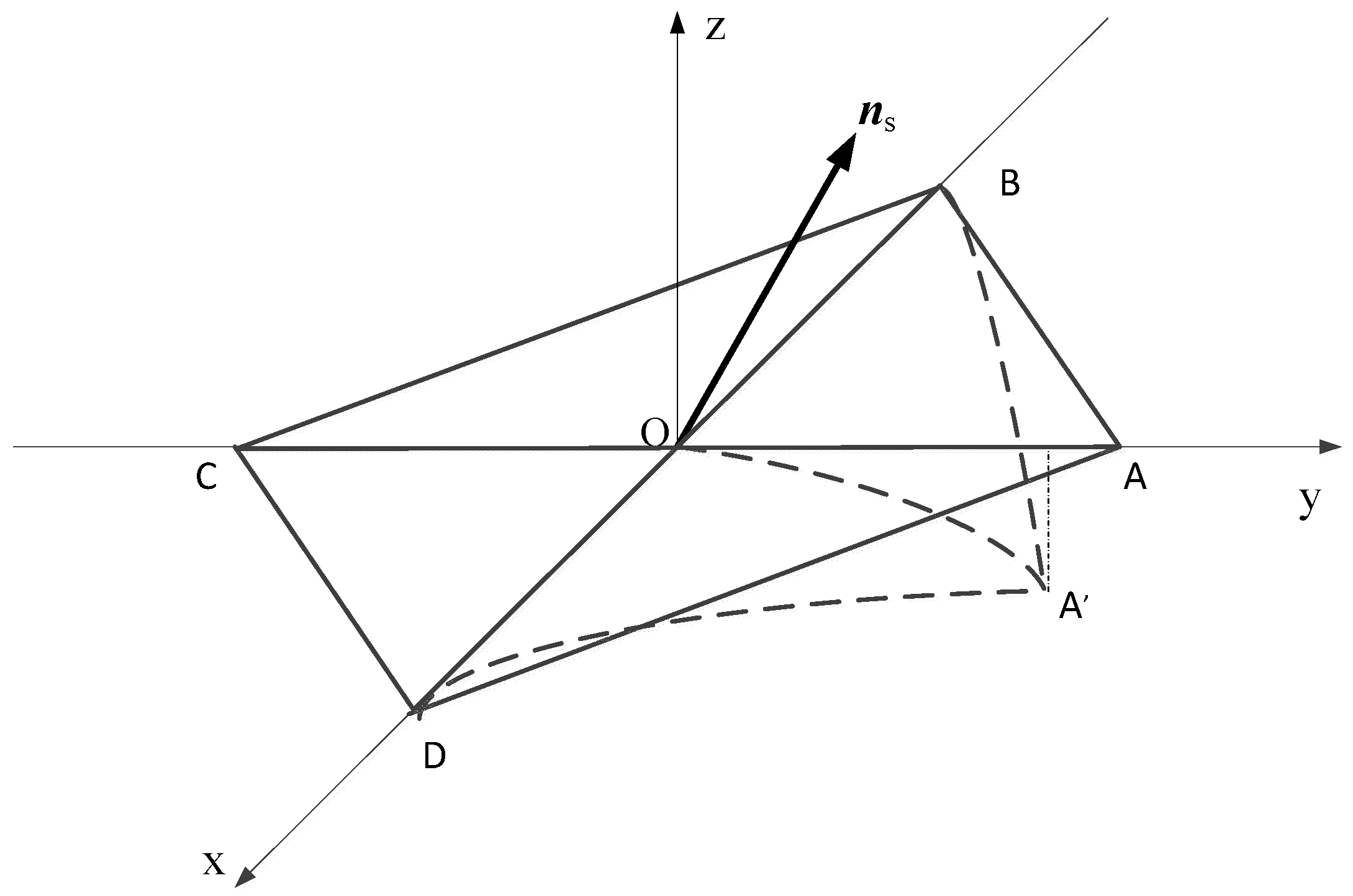
As shown in
Figure 1, Square solar sail ABCD is composed of four isosceles right-angled films with the reflecting surface and four booms that can independently bend. When all booms are free of deformity, the film is flat, the center of mass is at the sail’s geometric center, and the center of pressure coincides with the center of mass. The body-coordinate system O-xyz is established, choosing the geometric center of the solar sail as the original point. Boom OA is the positive
y-axis (pitch axis), OD is the positive
x-axis (yaw axis), and the normal direction of the solar sail is the positive
z-axis (spin axis). In this manuscript, the expressions are described in the body-coordinate system unless otherwise stated.
Considerable research about modeling beams with piezoelectric actuators has been conducted, and the exact solutions and analytical expressions of the bending problems were derived [
49,
50,
51]. This manuscript aims to verify the concept of solar sail attitude control using shape variation of booms. Different deformations do not affect the conclusion. To facilitate the calculation, the desired shape considered in the current phase has a simple analytical expression. For example, the deformation shape of boom OA has the analytical expression as follows [
52,
53]
where coefficient
a and exponent
p are both constants representing deformation. By changing the values of
a and
p, different deformation can be obtained.
Deformation can produce some sunlight, blocked by a part of the solar sail (self-shadowing effect), or produce multiple reflections between solar sail films (multi-reflection effect). For a solar sail with 30 m-long booms, assuming the coefficient a is 0.001 and the exponent p is 2, the self-shadowing effect appears when the angle between the sunlight and the solar sail plane is less than 0.06 radians. This means that the self-shadowing does not happen in almost all of the half-plane range. In order to avoid the above situation in the process of an attitude adjustment, the range of values of a and p are limited to 0 ≤ |a| ≤ 1 × 10⁻³ and 1 < p ≤ 2, respectively. In this case, the deformation is minimal relative to the size of the sail. In the maximum deformation case, the length of the projection of the 30 m boom in the Y-axis is 29.982 m and its maximum curvature is only 0.002, the effect of deformation on the areal density of the film is ignored in this manuscript.
It should be noted that wrinkles on the solar sail film are inevitable due to the flexibility of the film, the folding and unfolding process, and so on. The presence of millimeter-scale wrinkles can reduce the specular reflection fraction from 0.94 to 0.89 [
54,
55]. On the other hand, the boom deformation may lead to the formation of wrinkles, so it will also change the solar radiation pressure acceleration vector [
54,
56]. Therefore, a more accurate force model is needed in some mission scenarios. However, considering that this change is small, in a preliminary mission phase, the solar sail film is assumed as a perfectly reflecting surface before and after deformation.
The flexibility of the film also leads to structural deformation. To prove that the structural deformation is negligible in the following analysis, the response of the flexible sail with 30 m booms under SRP is simulated by ABAQUS. The results show that whether the solar sail is in the planar configuration or the deformed configuration, the maximum deviation of the film is small, and the deviation on the deformed side is significantly smaller than the planar side. Therefore, the effect of sail film vibration is not considered throughout this analysis. Before and after the deformation of the boom, the solar sail will be regarded as a rigid body and the sail film will be deformed along with the booms.
The two adjacent booms which deform simultaneously are not considered in this manuscript, because it is difficult to establish a mathematical model of the shape of the relaxed sail film and calculate the torque under the action of any sunlight vector. Furthermore, the shape of the relaxed sail film is easily disturbed by various factors, including the dynamic in the process of the solar sail flight and attitude adjustment. Therefore, it is difficult to effectively obtain the required torque by using the method of simultaneous deformation of adjacent booms according to needs.
In this case, the solar sail is always symmetrical to the x-z plane or the y-z plane, and the torque around the spin axis cannot be generated.
Compared with the attitude control method based on motion mechanism, the controllable reflectivity method dramatically reduces the structural complexity of the solar sail spacecraft. The introduced vibration amplitude is relatively small. The reflectivity modulation technology can switch the state by electric excitation, and the response speed is fast. However, this method also only produces pitch/yaw control torque when the solar sail is flat. In this manuscript, the boom’s deformation is considered to be combined with the controllable reflectivity method to generate a three-axes control torque.
As shown in
Figure 2, the four edges of the solar sail are covered with equal area electrochromic devices and are capable of state switching. Assuming that sunlight is fully absorbed when the device is turned off, the solar radiation pressure force applied on the electrochromic device can be expressed as [
57]
When the device is turned on, it is in a state of complete reflection of light and has the same optical properties as the solar sail’s surface, without covering the electrochromic device. In other words, the solar radiation pressure force can be expressed as
where
r0 stands for one astronomical unit,
P(
r0) is the pressure of sunlight at one astronomical unit,
P(
r0) = 4.5 × 10
−6 N/m
2,
r is the distance from the sail to the sun,
P(
r) represents the solar radiation pressure acting on the solar sail,
Aoff is the area of the electrochromic device which the state is turned off.
A is the sum of the area of the open electrochromic device and the surface area of the uncovered electrochromic device.
α is the angle between the normal of the solar sail
n and
ns.
ns is the unit vector of the sunlight direction in the body-coordinate frame, and it has the following expression:
where [
Xs Ys Zs]
T is the coordinate of the sunlight unit vector in the heliocentric ecliptic inertial reference frame,
φ,
θ and
ψ are the Euler angles which describe the attitude orientation of the body-coordinate system with respect to the heliocentric ecliptic inertial reference frame: first rotation around
x-axis at an angle
φ, then rotation around
y-axis at an angle
θ, finally rotation around
z-axis at an angle
ψ.
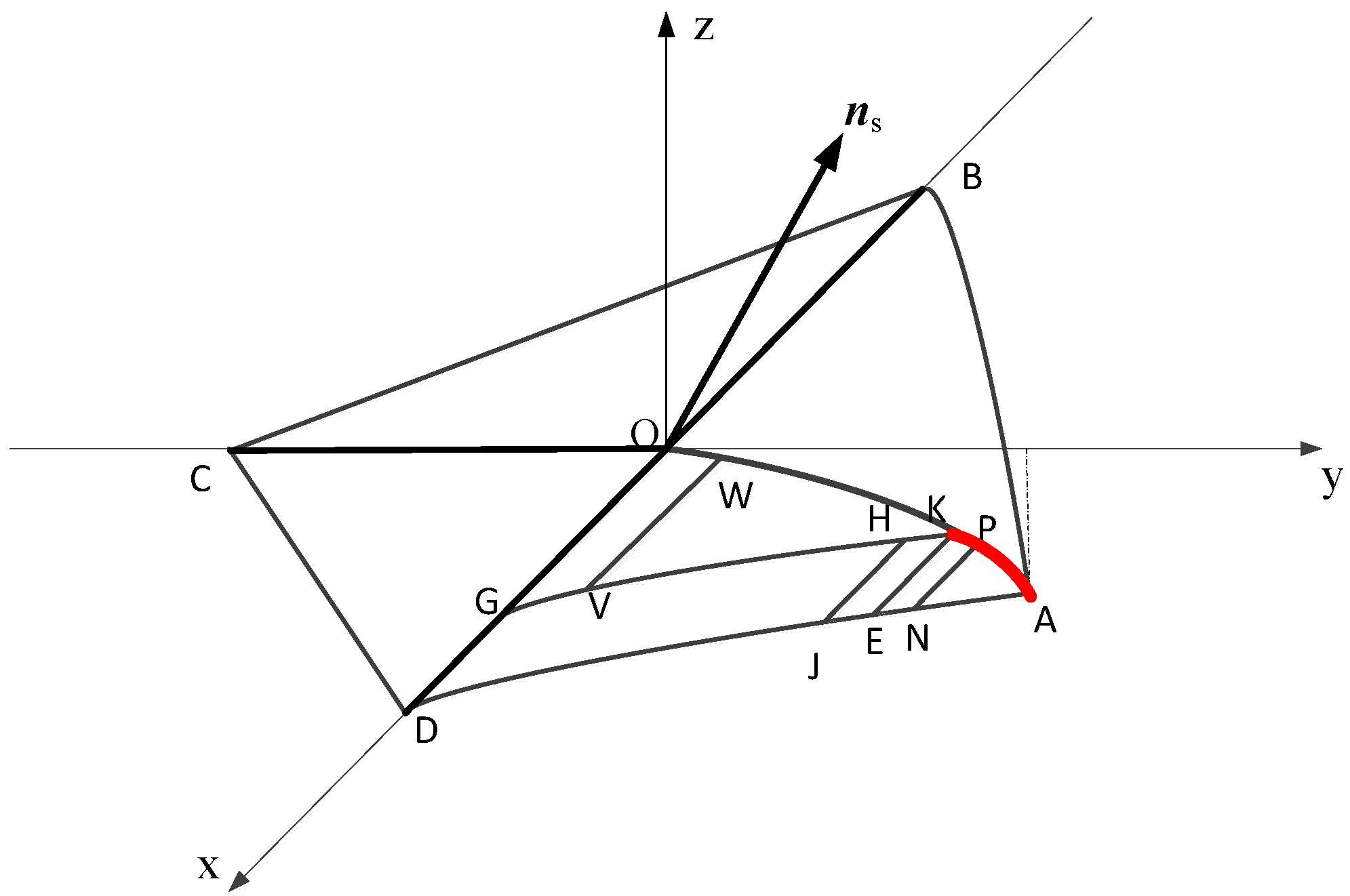
Taking the solar sail of the OAD portion as an example, the force and torque equations under the integrated method of bending deformation and adjusting reflectivity is derived. As shown in
Figure 2, the boom OA is deformed as described in Equation (1). The ADGK part is the electrochromic device in the closed state. As GK is parallel to AD, the length from A to K along the boom is used to represent the area of an electrochromic device in a closed state. The length from A to K along the boom can be defined as
L0.
L0 can continuously change in the range of (0,
Lmax). Therefore, the torque calculation of the OAD sail surface can be considered to consist of the ADGK (the part of the complete absorption of the sunlight) and the OGK (the part of the complete specular reflection of the sunlight). Both ADGK and OGK are composed of many rectangular elements parallel to BD. The solar radiation pressure on each element is a set of parallel forces of equal magnitude, so it can be regarded as the resultant force at the center of the rectangular element. The normal of each element can be calculated by
The coordinates of points K and A are defined as [0 ]T and [0 ]T, respectively. yk is the value related to L0, a, p and length of boom L. yf is the value related to a, p and L.
2.1. Torque Generated by OGK Part
The OGK part can be seen as a set of rectangular elements as OGVW part in
Figure 3. The length from O to W along the boom can be defined as
L(y), the coordinate of the center of pressure is [
y ]
T.
L(y) can be denoted as the function of the y coordinate of W, which can be written as
The vector from the center of mass of the solar sail to the center of pressure of the element OGVW is as follows
The area of the element can be calculated as
The force and torque generated by the element OGVW can be written as
After integrating Equations (9) and (10) over the range of (0, yk), we can obtain the force and torque relative to the center of mass of the OGK part.
2.2. Torque Generated by ADGK Part
For the convenience of calculation, the ADGK part, which absorbs the sunlight completely, is decomposed into two parts: DEKG and AEK.
DEKG can be seen as a set of rectangular elements as EKHJ part in
Figure 2, and the coordinate of the center of pressure is [
y ]
T, the vector from the center of mass of the solar sail to the pressure center of the element is as follows
The area of the element can be calculated as
The force and torque generated by the element EKHJ can be written as
After integrating Equations (13) and (14) over the range of (0, yk), we can obtain the force and torque of the DEKG part relative to the center of mass.
AEK can be composed of the rectangular elements as EKPN in
Figure 2, and the coordinate of the center of pressure is [
y ]
T, the vector from the center of mass of the solar sail to the pressure center of the element is as follows
The area of the element can be calculated as
The force and torque generated by the element EKPN can be written as
After integrating Equations (17) and (18) over the range of (yk, yf), we can obtain the force and torque of the AEK part relative to the center of mass.
The force and torque generated by the OAB, OCB and OCD portions have similar derivation processes. For the sake of distinction, deformation coefficient a1 and exponent p1 characterize the deformation of boom OA, while deformation of boom OB is measured by deformation coefficient a2 and exponent p2, deformation of boom OC is measured by deformation coefficient a3 and exponent p3, deformation of boom OD is measured by deformation coefficient a4 and exponent p4. The variables characterizing the area of the electrochromic device in the closed state on the OAD, OAB, OCB, and OCD portion can be defined as L1, L2, L3 and L4.
3. Torque and Force Analysis
This section will analyze various factors that affect the solar radiation pressure force and torque, based on the above research results.
From Equations (9), (10), (13), (14), (17) and (18), it can be seen that when the size and performance of the solar sail are selected, the solar radiation pressure force and torque are related to the values of
a and
p characterizing the deformation of the solar sail, the value of
L0 characterizing the area of an electrochromic device in a closed state, the distance from the sail to the sun
r, and the unit vector of the sunlight direction in the body-coordinate frame [
nsx nsy nsz]
T. According to the coordinate system transition matrix from the heliocentric ecliptic inertial reference frame to the body-coordinate system, [
nsx nsy nsz]
T are related to the three Euler angles
φ,
θ,
ψ and the coordinate of the sunlight unit vector in the heliocentric ecliptic inertial reference frame [
Xs Ys Zs]
T. In order to analyze the solar radiation pressure force and torque, the time history of the attitude angles, the distance from the sail to the sun and the coordinate of the sunlight unit vector in the heliocentric ecliptic inertial reference frame [
Xs Ys Zs]
T, in the rendezvous mission with Asteroid 2000 SG344 in literature [
58], are used as relevant parameters. According to the position and velocity and the direction of the spin axis of the solar sail, the attitude angles
φ and
θ, describing the body-coordinate system with respect to the inertial reference frame, can be calculated. Since the orbital driving force of the solar sail in the plane state is not a function of the spin angle
ψ, the spin angle is not included in the literature [
58]. Unless otherwise specified, the relevant parameters used in this section are shown in
Table 1. For the sake of distinction, in the following figures, the solid line is used to indicate the deformation of the booms in the
x-axis direction, the dashed line is used to indicate the deformation of the booms in the
y-axis direction, and different colors are used to indicate different electrochromic device control.
3.1. The Influence of Spin Angle ψ on Force and Torque
In this manuscript, the variables (
a1,
a2,
a3,
a4) that characterize the deformation of the booms, and the variables (
L1,
L2,
L3,
L4) that characterize the area of the electrochromic devices in a closed state, are used as the control variables. This section studies the influence of the spin angle on the force and torque of the deformed solar sail and provides a reference for selecting the control target of the spin angle. The effects of the spin angle on the force and torque, under different deformation and variable reflectivity device states, are studied. As a comparison, the data in literature [
58] is used as reference variables, and the changing trends under different Euler Angles
φ and
θ are studied.
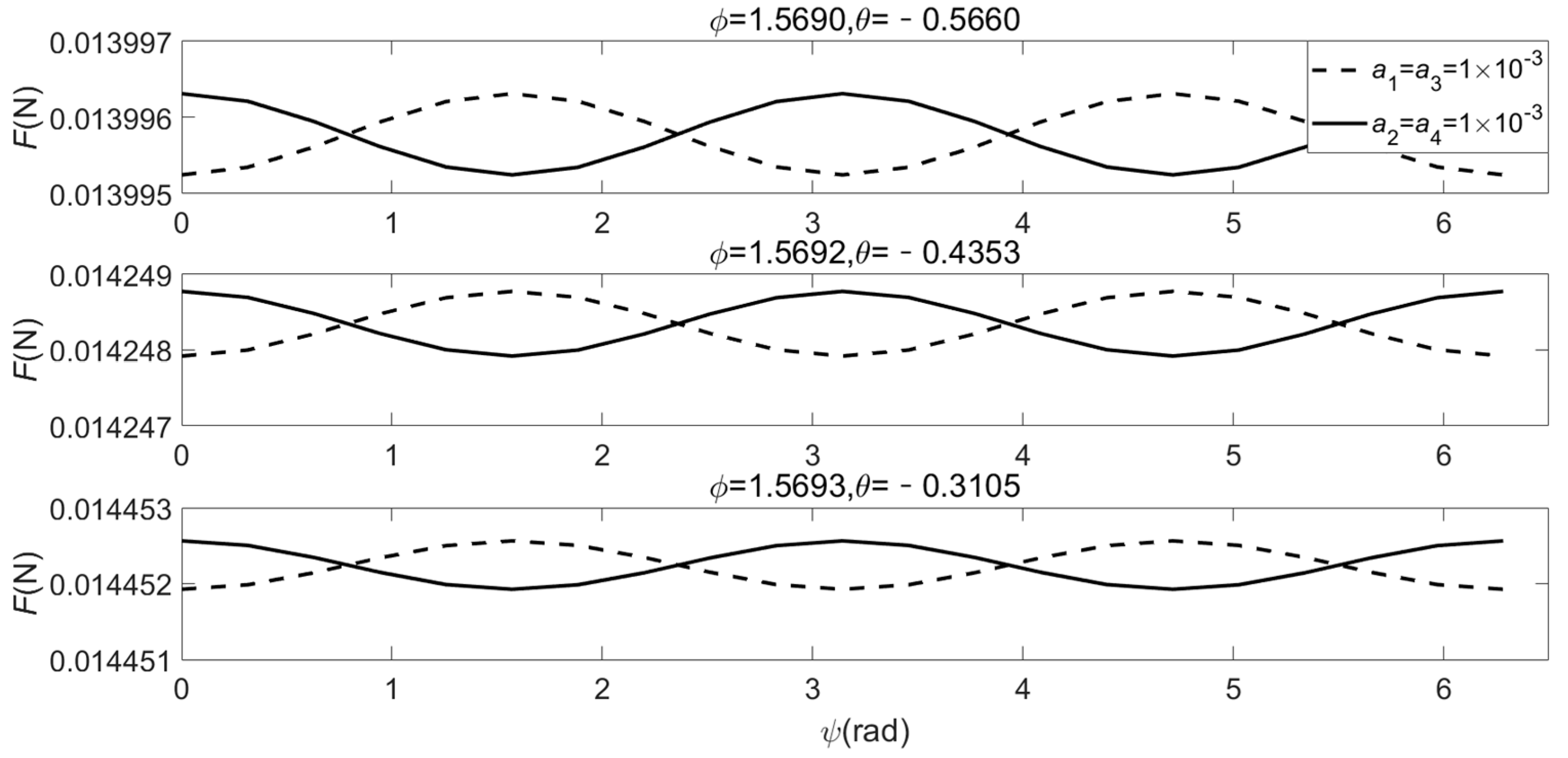
For a flat solar sail, the SRP force is independent of the spin angle ψ, but in the deformation stage of the solar sail the magnitude of force will change with the value ψ.
Figure 3 and
Figure 4 show the effect of the spin angle
ψ on the SRP force and torque under the different deformation of the solar sail. The parameters are shown in
Table 2.
In order to study the trend of the force and torque under different Euler angle conditions, from the departure time of the solar sail for the rendezvous mission with Asteroid 2000 SG344, the Euler angles φ and θ, corresponding to every 10 days apart, is selected as the reference variable.
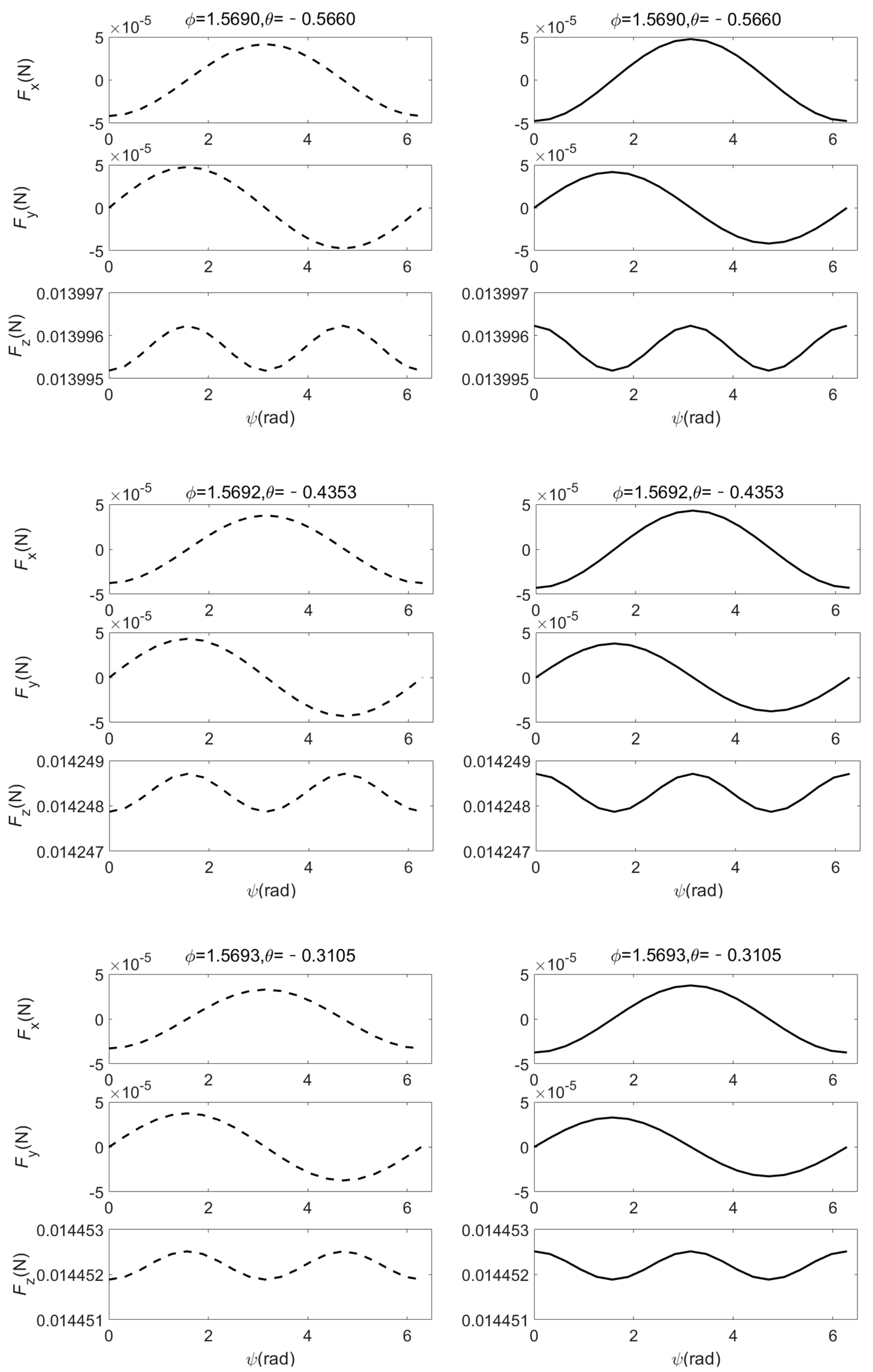
Figure 3 shows that the magnitude of the solar radiation pressure force periodically varies with a sine or cosine curve. Whether it is the deformation of the booms in the
x-axis direction or the booms in the
y-axis direction, the amplitude and period of the solar radiation pressure force change are the same, and the phase angle corresponding to the amplitude appears at
ψ =
(
n = 0,1,2,3,4).
Fx and Fy show the same trend under different deformation conditions, indicating that the deformation of the booms in different directions will not change the projection of the force on the x-y plane of the body coordinate system for any spin angle, but the deformation of the booms in different directions makes the trend of the force Fz in the z-axis direction different. In general, the deformation of booms in different directions has little effect on the solar radiation pressure force.
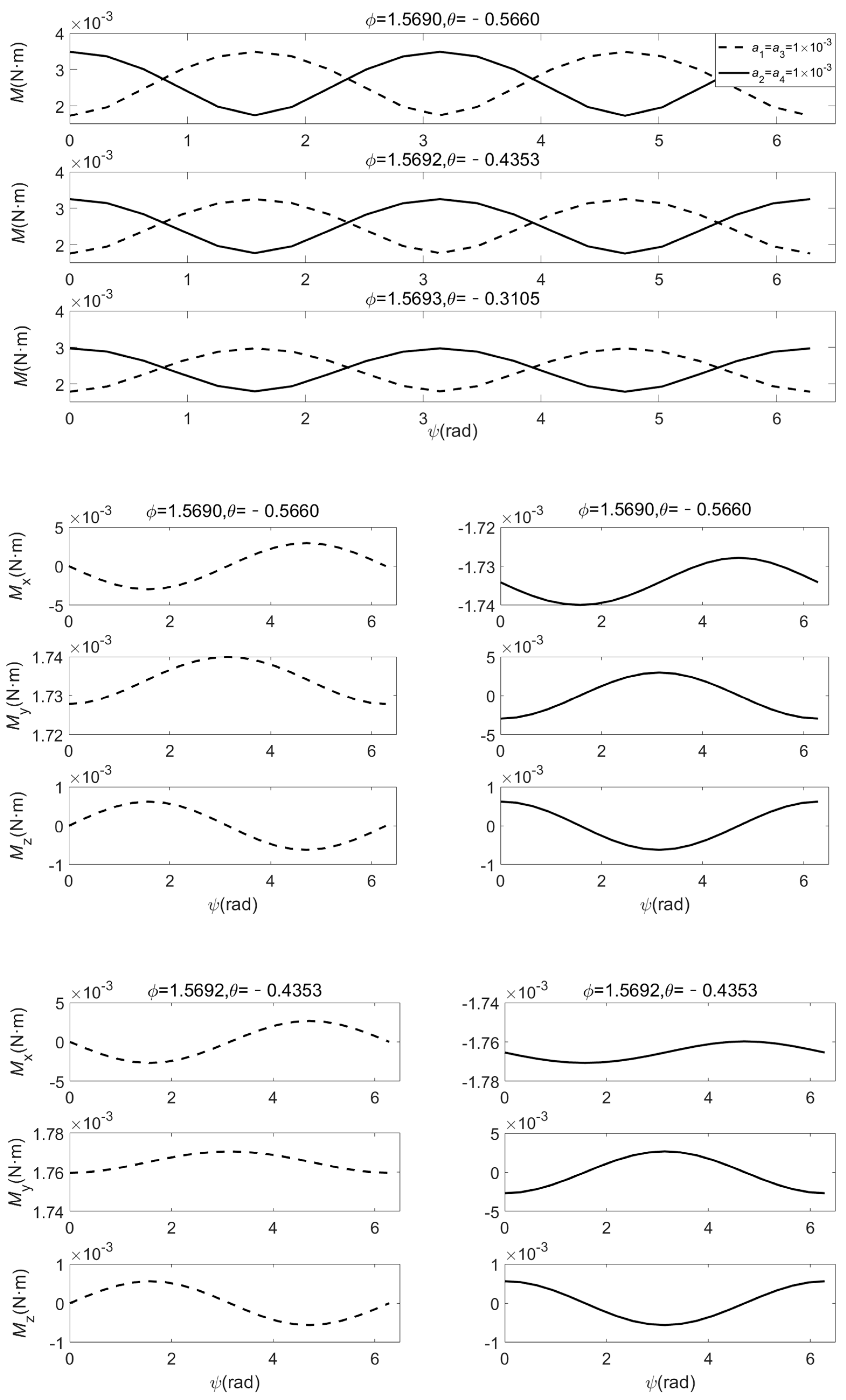
Figure 4 shows that the magnitude of the torque also periodically varies with a sine or cosine curve. The deformation of booms in different directions will affect the type of curve but will not affect the amplitude and period. Differing from the change in the force, the deformation of booms in different directions will change the trend of
Mx,
My and
Mz with the value of
ψ. This will affect the attitude control process of the solar sail.
Figure 3 and
Figure 4 show that different Euler angles
φ and
θ will cause the amplitude of the curve of the solar radiation pressure force and torque to differ, but will not affect the trend, period, and phase angle corresponding to the amplitude.
3.2. The Influence of The State of The Electrochromic Devices on The Force and Torque
In this section, we study the influence of the state of the electrochromic device as one of the control variables on the force and torque. In the previous section, we have already seen that when the relative position of the state distribution of the electrochromic device is the same, the deformation of the booms in different directions will not affect the period and amplitude of the curve of the force.
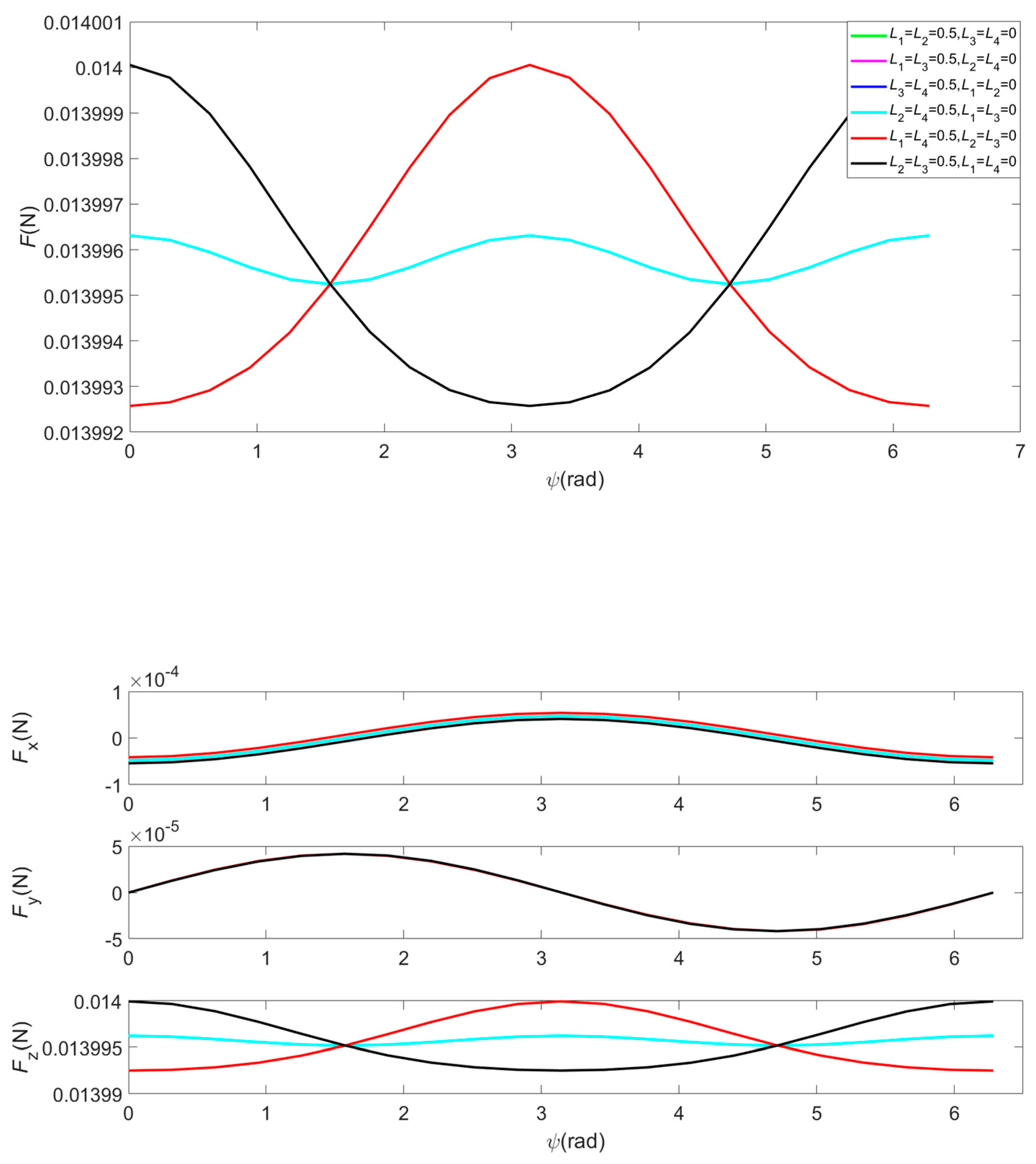
Figure 5 shows the trend of solar radiation pressure force with
ψ under different state distributions of electrochromic devices when the booms OB and OD are deformed. Although the trend of the force is still a trigonometric function curve, the amplitude and period of the curve are not the same. As shown in the
Figure 5, when the state of the electrochromic device is symmetrically distributed with respect to the
x-axis (for example,
L1 =
L4 = 0.5 m,
L2 =
L3 = 0 m), the amplitude of the curve is larger, and the period is longer. This change is mainly caused by the change of
Fz. Obviously, the distribution of the state of the electrochromic device has a greater impact on the force than the deformation of the booms in different directions.
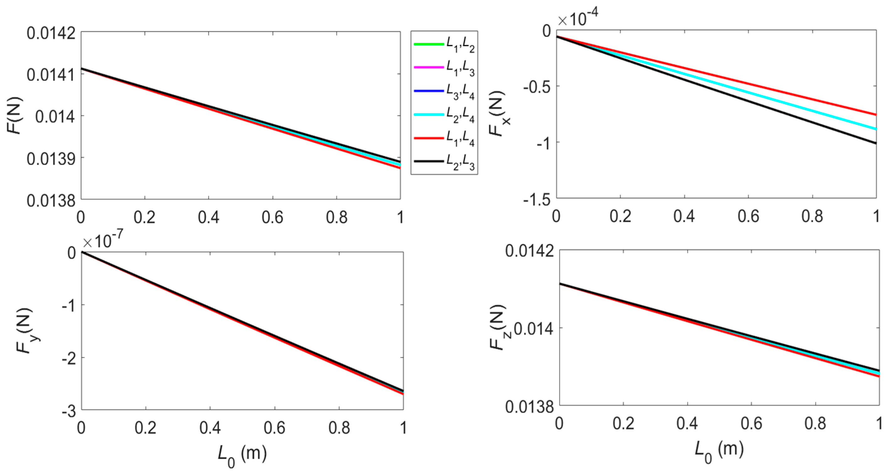
Figure 6 and
Figure 7, respectively, show the trends of the force and torque with the state of the electrochromic device when the booms OB and OD deform at the same time and the deformation coefficients are
a2 =
a4 = 1 × 10
−3. In the legend, ”
L1,
L4” indicate that the values of
L1 and
L4 increase from 0 to 1 at the same time, and the values of
L2 and
L3 are always zero. The rest of the illustrations are similar.
Figure 6 shows that the magnitude of the force decreases when the area of the electrochromic device, in a closed state, increases. Comparing Equations (2) and (3), we can see that when the angle between the normal of the element and the sunlight direction meets the condition cos
a > 0.5, the force generated by the film covered with the electrochromic device in the closed state is less than the force generated by the film that does not cover the electrochromic device, or when the electrochromic device is in the open state. At this time, the larger the area of the electrochromic device in the closed state, the smaller the force generated by the solar sail. It can also be seen from the figure that the magnitude of the force monotonously decreases with
L0, which characterizes the area of the electrochromic device in the closed state. For the distribution of electrochromic devices ”
L1,
L2”, ”
L1,
L3”, ”
L3,
L4” and ”
L2,
L4”, the trend of force has the same slope, but for the distribution of electrochromic devices ”
L1,
L4” and ”
L2,
L3”, the slope of the lines are different. The reason for this is that for the deformation of the booms in the
x-axis direction (OB and OD), the angle between the sunlight and the film or electrochromic devices on both sides of the
y-axis is not the same. However, due to the small deformation of the solar sail, the change in the slope is also small.
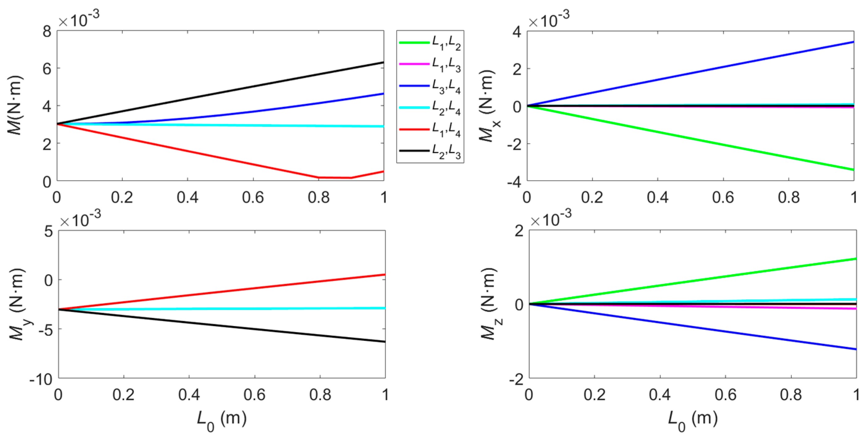
As the torque is not only related to the force, but also related to the position of the element, the trend of the torque is different from the trend of the force. For example, when the booms in the x-axis direction are deformed, the state distributions of “L1,L2” and “L3,L4” are both symmetrical to the x-axis, the trend of the force and torque are the same. The state distributions of “L1,L3” and “L2,L4” are both symmetrical to the original point, the trend of the force and torque are also the same, but the trend of the torque in the state distributions of “L1,L2” is not the same as the trend of the torque in the state distributions of “L1,L3”, although the trend of the force in the two states is the same.
In addition, the trend of the torque with L0 does not show a monotonous decrease law similar to the force. Especially for the state distributions of “L1,L4”, the magnitude of the torque with L0 first decreases and then increases. This is because, in this case, the torque around the y-axis has undergone a transition from negative to positive, and its magnitude first decreases and then increases.
It is difficult to obtain the torque required for three-axis attitude control only by adjusting the value of
L0. As shown in the
Figure 7, when the state distribution of “
L1,
L2”, “
L1,
L3”, “
L3,
L4”, “
L2,
L4” and “
L2,
L3” is adopted, only the negative torque around the
y-axis can be generated, and except for “
L2,
L3”, the torque does not change in the rest of the state distribution. For the state distribution of “
L1,
L4”, although the positive torque can be generated, no torque around
x-axis is generated, and the torque around
z-axis and the positive torque around the
y-axis are also very small. In summary, in order to realize the three-axis attitude control of the solar sail, it is necessary to control the deformation of the solar sail and
L0 at the same time.
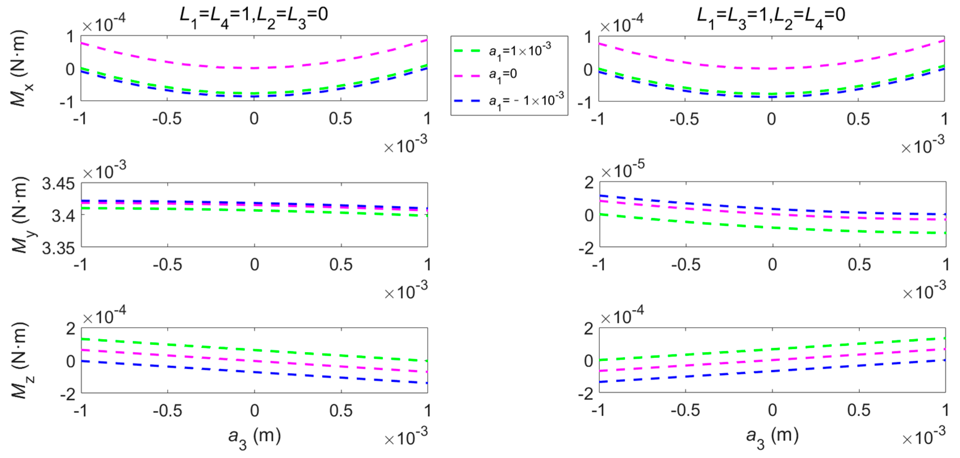
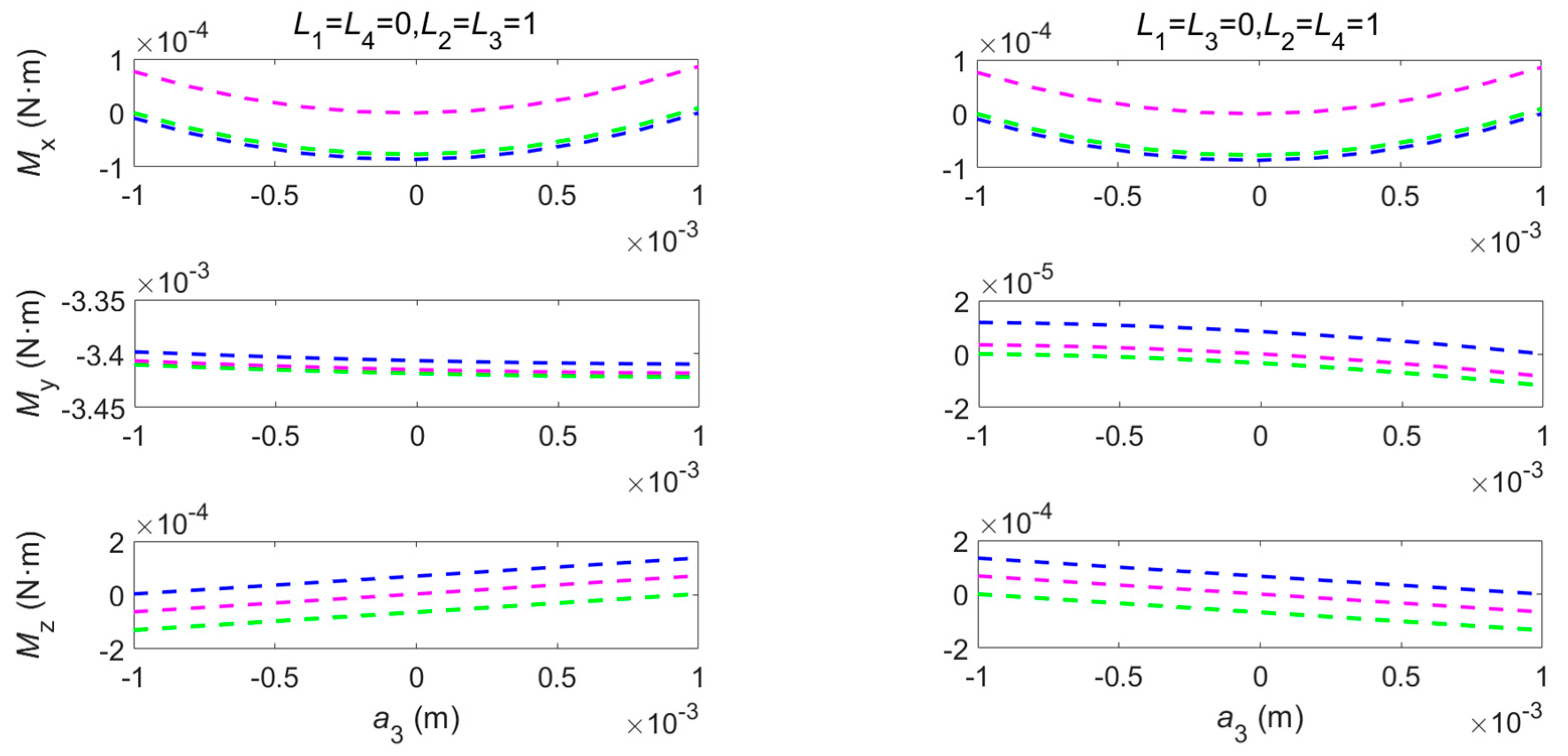
3.3. The Influence of Deformation on The Force and Torque
Since changing the values of a can realize continuous changes in the shape of the boom, for the sake of simplicity, the deformation exponent p is set at 2 in this manuscript, and the deformation of the boom is achieved by only controlling the variable a. Next, we will analyze the influence of deformation coefficient a on solar radiation force and torque.
In the legends of
Figure 8 and
Figure 9, “
a1 = 1 × 10
−3” means that the boom OA always keeps an upward bending deformation, and the deformation coefficient of the boom OC continuously changes; “
a1 = 0” means that the boom OA is not deformed at all; “
a1 = −1 × 10
−3” means that the boom OA always keeps bending downward.
Figure 8 shows that the forward and reverse three-axes torque can be obtained through the coordinated control of
L0 (characterizing the area of electrochromic device in the closed state) and
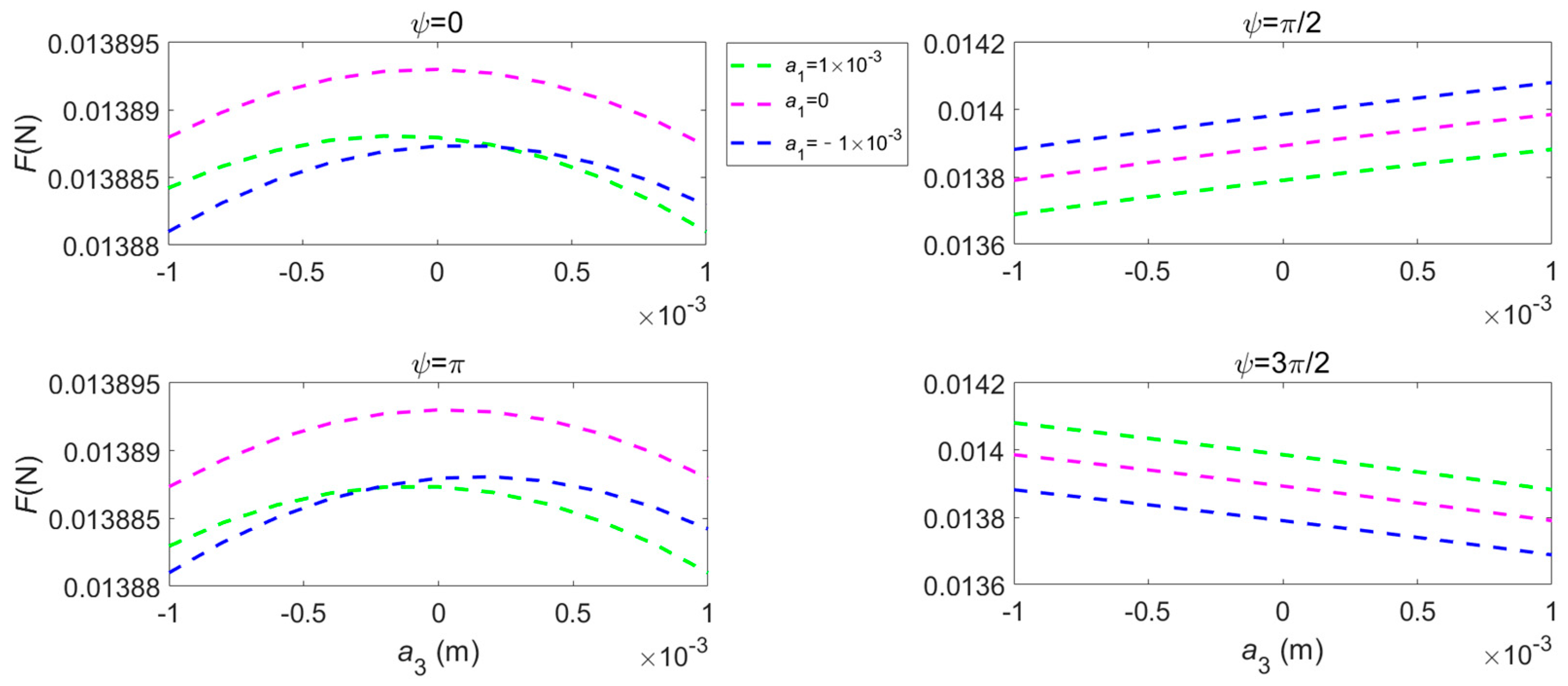
a (characterizing the deformation of the solar sail), thus achieving the three-axes attitude control of the solar sail.
Figure 9 shows the trend of the force’s magnitude with the deformation of the solar sail. Since the force is almost unaffected by the distribution of electronic devices state, here is only the case when the distribution state is
L1 =
L4 = 1 m,
L2 =
L3 = 0 m.
Different deformation combinations of the booms make the force show different changing trends, and under different spin angles’ conditions, the trends and ranges of the force are also different. Since the deformation and spin angle of the solar sail will change the relative orientation of the solar sail and the sunlight, which will affect the force, the adjustment of the spin angle can be achieved through the attitude control method proposed in this manuscript. In the actual flight mission, the orbital force of the solar sail can be controlled by adjusting a and L0.
4. Attitude Maneuver
Since the shape variation time of the boom is much shorter than the time of the attitude adjustment (e.g., the deformation time under the action of piezoelectric ceramics is only the order of milliseconds), the solar sail will be regarded as a rigid body before and after the boom’s deformation. In such a situation, the rigid body dynamics equation is still applicable.
4.1. Attitude Dynamics and Kinematics
The Euler angles and angular velocity can describe the attitude kinematics and dynamics of the solar sail. The attitude of the solar sail, with respect to the heliocentric ecliptic inertial reference frame, can be described by three Euler angles
φ,
θ and
ψ. The attitude kinematics equation describes the rate of change of the attitude angle during attitude maneuvering, which can be obtained from the rotation of the Euler angle. The attitude kinematics equations are as follows
The attitude dynamics equation can be obtained from the angular momentum theorem of a rigid body. The attitude dynamical equation is as follows
where
Ib and
ωb is the projection of the inertia matrix and the angular velocity vector of the solar sail in the body-coordinate system, respectively.
Mb is the projection of the solar radiation pressure torque vector. Their scalar forms are as follows
The deformation will change the inertia matrix, but the variation of the inertia matrix is small due to the small variation. Therefore, for the sake of simplicity in the calculation, the change of the inertia matrix is ignored in attitude dynamics.
Substituting Equations (21) into (20), the scalar form of the attitude dynamics equations are as follows
The attitude control and orbit control of solar sails are strongly coupled. That is to say, the attitude change in the solar sail will affect the orbital driving force of the solar sail, and the change in the orbit position of the solar sail will affect the magnitude of the attitude control torque. Therefore, the influence of orbit position change should be considered in the attitude adjustment.
The orbit dynamic equations of the solar sail can be given as
where
r and
V are the position and velocity vectors.
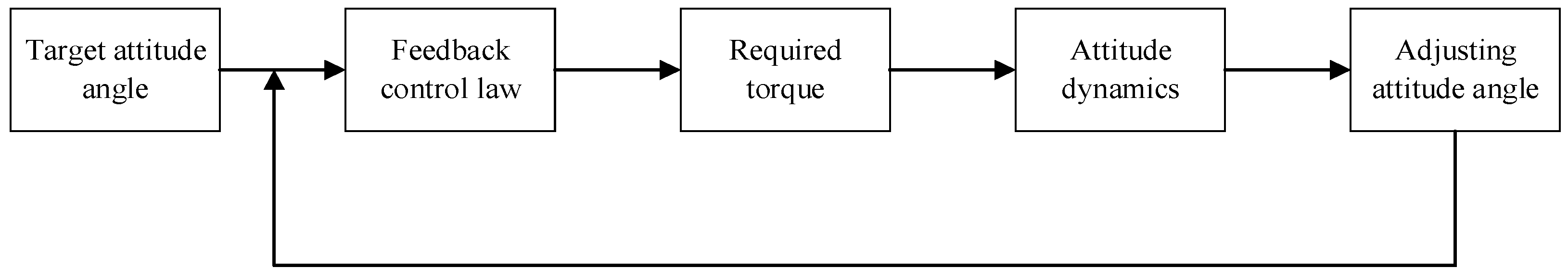
4.2. Control Law
The attitude adjustment process of the solar sail is shown in
Figure 10. PD feedback control law is adopted to control the attitude of the solar sail. The control law is expressed as follows
where Δ
e represents the error between the actual value and the target value of the solar sail attitude angle, Δ
ω represents the error between the actual value and the target value of the solar sail angular velocity.
U represents the maximum torque that can be obtained in the control process, which is related to the attitude angles (
φ,
θ,
ψ) and control variables
L0,
a and
p. sat means a saturation controller. The torque cannot exceed the maximum control force in the process of attitude adjustment.
In order to reduce the vibration of the solar sail in the process of attitude adjustment, the overshoot is expected to be as small as possible under the condition that the steady-state error accuracy meets the requirements. Increasing KP is beneficial to reduce the system steady-state error and improve the response speed, but it will also cause oscillation. Increasing KD is beneficial to reduce overshoot and improve the stability of the control system. By adjusting KP and KD to appropriate values, the desired attitude control process can be obtained.
4.3. Numerical Examples
In the preliminary design of the solar sail mission, the attitude angle is usually taken as the control variable of the SRP and assumed to change instantaneously and continuously. However, during the flight, the attitude adjustment usually needs to be periodically conducted by means of attitude control methods. In this section, the effectiveness of the proposed attitude control method in a single attitude adjustment process is evaluated.
The attitude profiles obtained in the literature [
58] for a solar-sail orbital transfer mission is considered. In the literature, a solar sail with the lightness number
β = 0.08 is used to realize the rendezvous mission from the earth to the Astroid 2000 SG344. Assuming that the attitude angles can change instantaneously and continuously, the solar sail will rendezvous with the Astroid 2000 SG344 after 360.368 days. Without loss of generality, in the actual flight process, it is assumed that the attitude angles of the solar sail are adjusted once a day. The Rest-to-rest Attitude Angle Adjustment scheme is used to realize the one single attitude maneuver. Simulation parameters are shown in
Table 3.
Although there are eight control variables (
L1,
L2,
L3,
L4,
a1,
a3,
p1,
p3) that can control the torque of the solar sail, the torque can reach the required accuracy only with six control variables. In order to simplify the calculation, make
p1 =
p3 = 2, the range of other control variables is limited to: 0 ≤ (
L1,
L2,
L3,
L4) ≤ 1 m, −1 × 10
−3 ≤ (
a1,
a3) ≤ 1 × 10
−3. The attitude change process of the solar sail is plotted, as shown in
Figure 11.
Equations (19) and (22) show that the attitude angle and angular velocity of the solar sail are coupled. When Euler angle φ and θ are adjusted, ψ will also change at the same time.
For example, when the Euler Angles φ and θ are adjusted from [1.569046, −0.565996] to [1.569058, −0.552697] only by booms deformation, the value of ψ change from 0 to 6.712 × 10⁻⁶ due to the coupling effect. Although this is a very small value, the uncontrolled spin angle will seriously deviate from the expected value with the accumulation of time in long-term missions where spin angles are required.
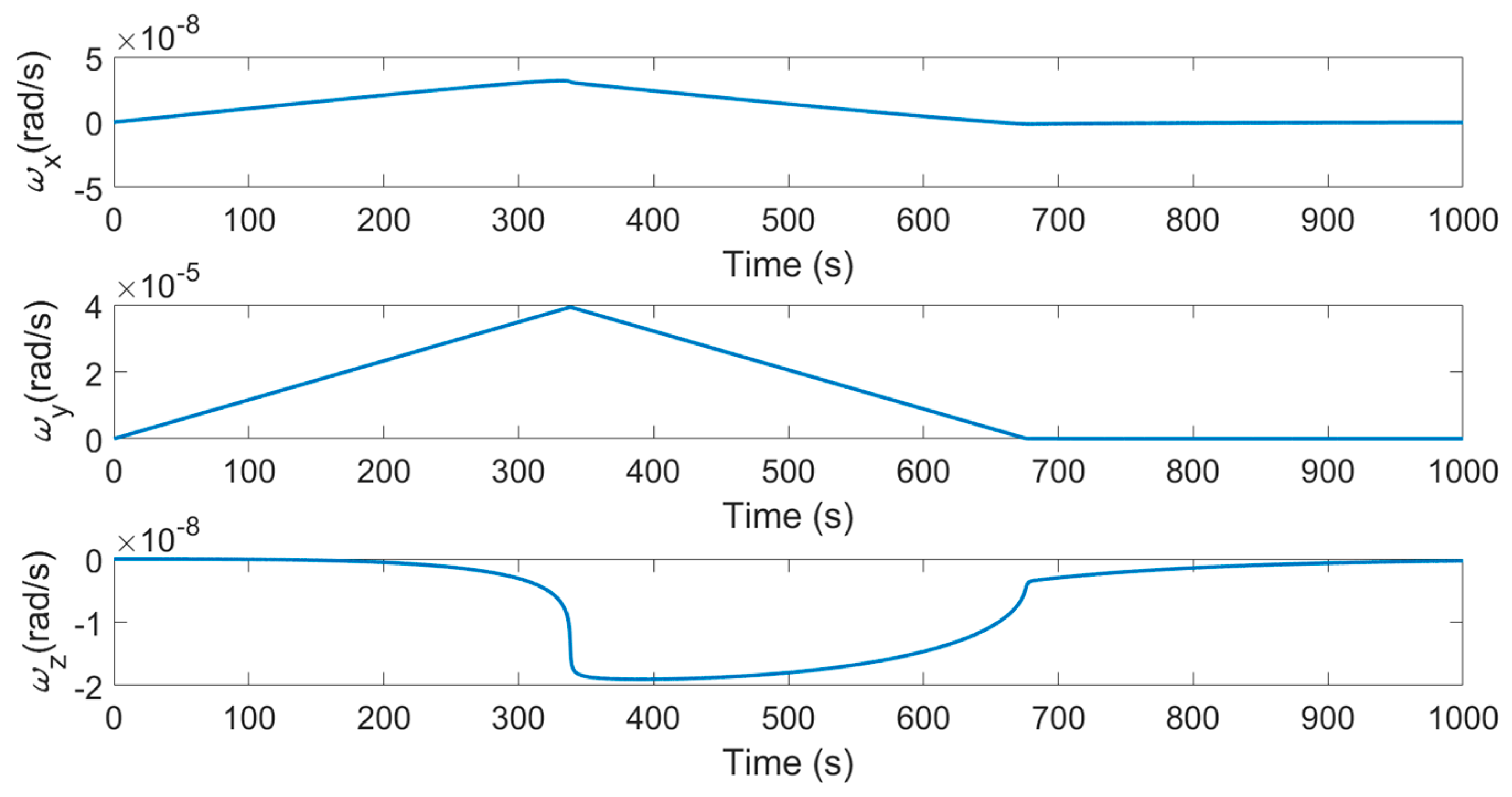
It can be seen from
Figure 11 and
Figure 12 that the attitude angle and angular velocity of the solar sail achieve the expected control objectives under the action of three-axes torque.
Figure 11 shows that although the spin angle
ψ changes due to the coupling effect, the spin angle eventually returns to zero.
Figure 12 shows that the angular velocity of the solar sail has also returned to zero.
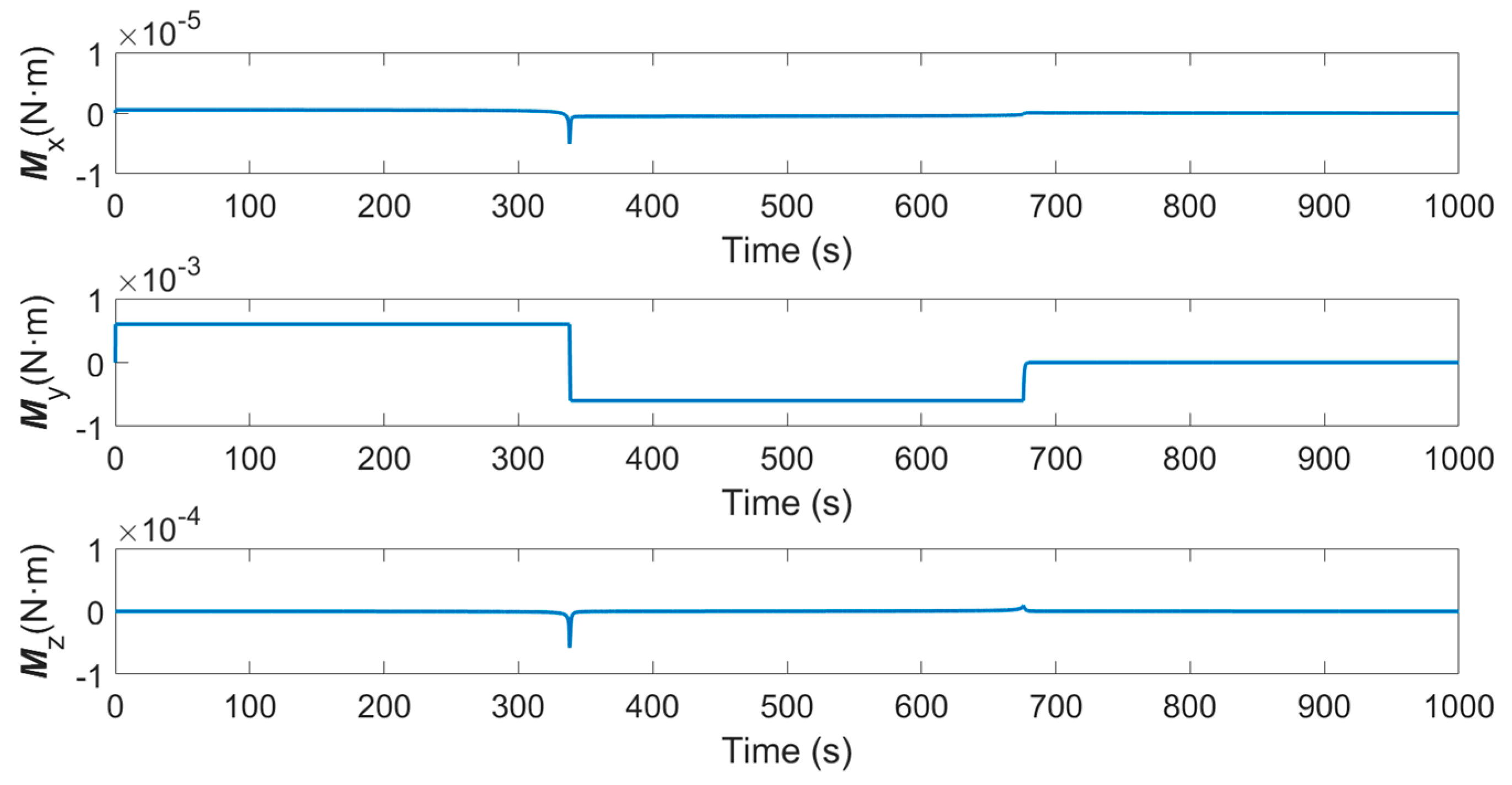
Figure 13 shows the required three-axis control torque during the attitude adjustment process. Due to the small adjustment of Euler Angle
φ and the small change in
ψ value caused by the coupling effect, the required torque
Mx around the
x-axis and the torque
Mz around the
z-axis are very small, and the angular velocities
ωx and
ωz are also both small. In contrast, due to the larger adjustment range of Euler Angle
θ, the required control torque
My is also larger, and
ωy also changes significantly.
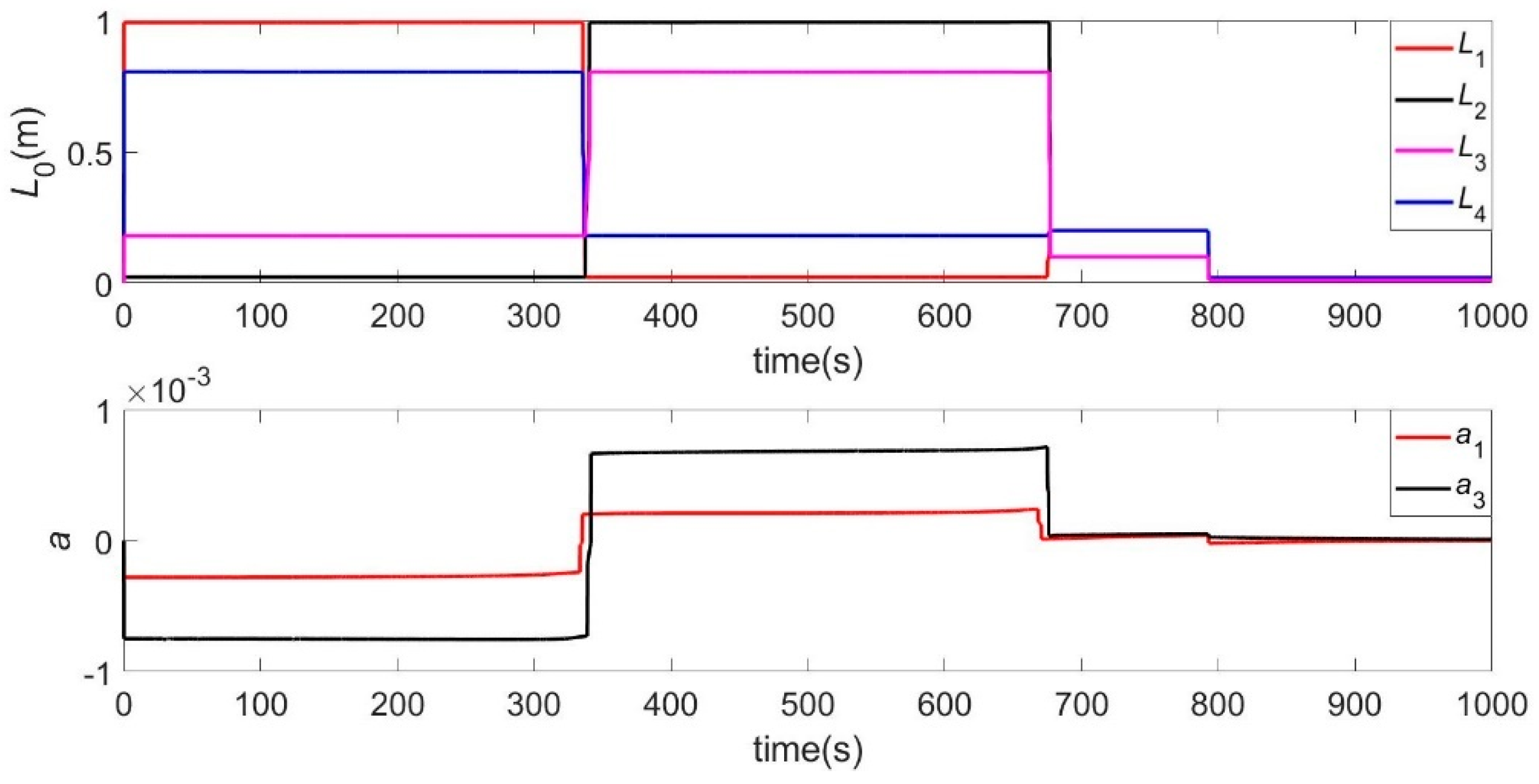
It can be seen from
Figure 14 that the deformation coefficient of the boom does not dramatically change, which indicates that frequent deformation control of the solar sail is not required during the attitude adjustment process. A relatively gentle deformation process is beneficial to reduce the vibration caused by deformation.


