1. Introduction
Weight reduction together with the improvement of damage tolerance capabilities have always been the key design aspects in the development of structural components for the aerospace/aeronautical industry.
As a consequence of this everlasting challenge, composite materials have been introduced in aerospace applications more than 40 years ago, and now aerospace is still the industrial sector where composite are of major practice. Indeed, composites are characterised by significantly higher strength-to-weight and stiffness-to-weight ratios compared to metallic materials; hence, they have been, in the last years, heavily adopted to replace metals [
1,
2,
3,
4,
5,
6,
7]. Examples of replacement activities can be found in the work of Baker, A. A., et al. that describes a cost-efficient methodology to replace metallic honeycomb panels with more durable stiffened graphite/epoxy composite panels [
6].
Another example of metal replacement can be found in [
7], where a new approach to aircraft design, replacing the classic metal structure with a composite wing whose shape was inspired by the Voronoi pattern (dragonfly wing), was established. This approach allowed considerably saving weight if compared to the equivalent metallic structure.
The adoption of composite materials as a substitute of metal alloys has also extended to industrial sectors other than aerospace. Indeed, Ning Haibin et al. [
8] designed and produced an air conditioning roof door of a transport bus by replacing aluminium components with composites, allowing the achievement of excellent results in terms of mechanical performance and weight saving.
Metal replacement with composite has become a common practice in the last years, leading to the growth of focused research centres over the world finalised to promoting the development of advanced manufacturing and design technologies for composites [
9].
However, even if composites may help to reduce weight and increase mechanical performances, they are characterised by damage mechanisms which are radically different from those exhibited by metallic materials and, in many circumstances, can become critical for composites applications. Damage mechanisms in composites can be easily classified into intra-laminar (fibre and matrix breakage) and inter-laminar (delaminations) damage [
10,
11,
12,
13,
14].
Due to this critical damage behaviour, it can be mandatory, during the design phase of a new structural component, to perform detailed numerical analyses taking into account the failure mechanisms and their interactions.
In the present work, a detailed finite element model was developed, aimed to evaluate the feasibility and effectiveness of replacing metal components with carbon fibre-reinforced polymers in an executive aircraft wing. This numerical model takes into account the constraints arising from the manufacturing process to support, step by step, the fabrication of the component. The manufacturing technology considered for the fabrication of the investigated composite wing was the “Liquid Resin Infusion” (LRI).
LRI is a closed mould technology which, thanks to an imposed depression generated by a vacuum pump, allows “infusion” in liquid form through a dry preform. The LRI can be defined as an out-of-autoclave cost-efficient technology compared to other technologies, especially for the low materials and storage costs, even if the tooling cost may be relevant [
15,
16,
17,
18]. Although the LRI infusion process adopts low-cost materials it is still able to provide the composite component with considerable mechanical performance and stunning geometric tolerances, which can be compared to those of other more expensive manufactured technologies such as autoclave with Pre-Preg.
However, LRI technology performances are strongly dependent on the permeability of the fibres to resin during the process. For example, fabrics with more space between fibres are more permeable, and this greatly influences the LRI technology output in terms or rich resin areas. Hence, with this technology, it is necessary to define not only the correct layup to be used according to the required mechanical performances, but also the manufacturing constraints. All these process constraints were carefully considered in the FE model preparation. In particular, the transition between the different stacking sequence zones was controlled by implementing ramps in which the number of layers of the laminate was gradually reduced. Furthermore, in order to guarantee the symmetry conditions of the laminate, the elimination layers process was always carried out from the outside towards the middle plane of the laminate.
In the second section of this paper, the theoretical background considered for the developed numerical model to accurately represent the real physical behaviour of the composite structure subjected to the service loads is introduced. In the third section, the characteristics of the FE model developed in the finite element environment MSC NASTRAN are described. The fourth section is focused on the assessment of the numerical results obtained from the model. Actually, in this section, the numerical outputs (from linear and buckling analyses), in terms of strains and failure criteria, are verified and discussed together with instability performances of the designed wing with metal components replaced with CFRP.
2. Theoretical Background
In order to take into account the real operational conditions in describing the physical behaviour of the composite wing, it was necessary to consider, in the frame of the design activities, the following numerical and analytical (hand) methodologies:
the Huth–Schwarmann method was used to calculate the shear and stiffness of the fasteners;
a Nodal Constraint approach was used to link the degrees of freedom of the nodes of the different geometric model parts (separately meshed);
failure criteria for metallic alloys and composite materials were adopted to assess the structural integrity of both composite and metal components;
bearing factors were taken into account to investigate the stress distribution in the fastening zones for both metal and composite components;
linearized buckling analyses were adopted to investigate the structural stability under service loads.
The description of these methodologies is presented in the following subsections.
2.1. Huth–Schwarmann Method
There are many different types of fasteners in an airplane wing. A list of the fasteners considered in this work is provided below:
To calculate the shear and stiffness of these fasteners, several semi-empirical methods can be implemented. In this work, the Huth–Schwarmann method was adopted by evaluating the axial and shear stiffness of one-dimensional FEM elements called “Cbush”, used to model the fastener in the adopted finite element environment MSC NASTRAN.
According to the adopted method, the stiffnesses to be attributed to each fastener are evaluated by means of the following relations.
where:
D is the fastener diameter
t1 and t2 represent the panels thickness
E1 and E2 are the in plane Young Modulus of the material considered
Ef is the Young Modulus of the fasteners.
According to the adopted formulation, the stiffness depends on the diameter of the fastener, on the properties of the plate, on the type of connection (bolted metallic, riveted metallic or bolted graphite/epoxy) and, finally, on the coefficient “n”, which is related to the joint type (single or double lap). The shear stress in single-lap joints is:
The shear stress in double-lap joints is:
with:
Equations (3) and (4) highlight that in single-lap joints, the shear stress P is equal to the applied tension force
F, while in the case of double-lap joints, the shear stress P is equal to half the applied tension force
F.
Figure 1 shows a schematic illustration of single-lap and double-lap joints.
Since the composite materials are not isotropic, the previous formulation was slightly varied by differentiating the shear stiffness along direction 1 (0°) and direction 2 (90°) of the laminate.
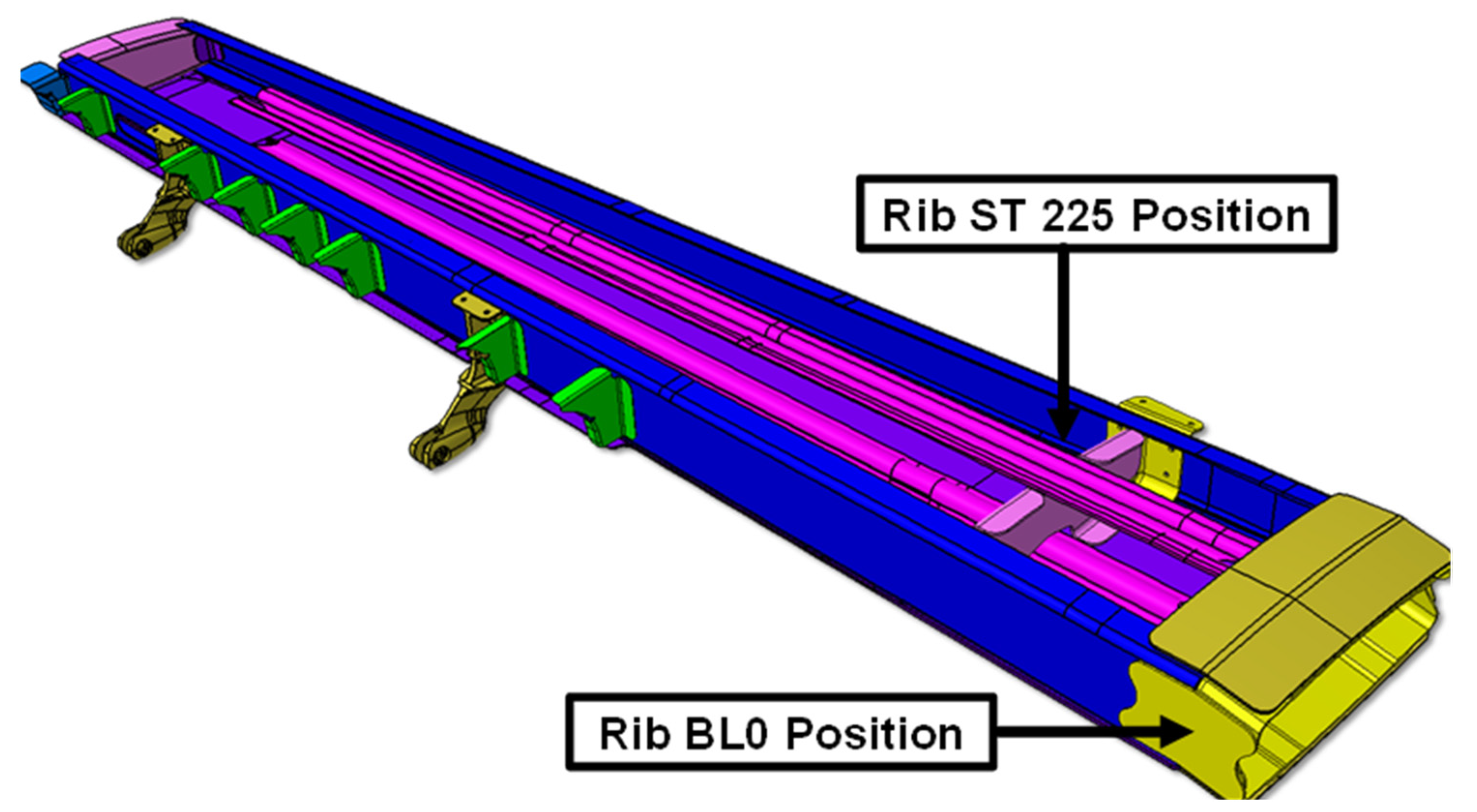
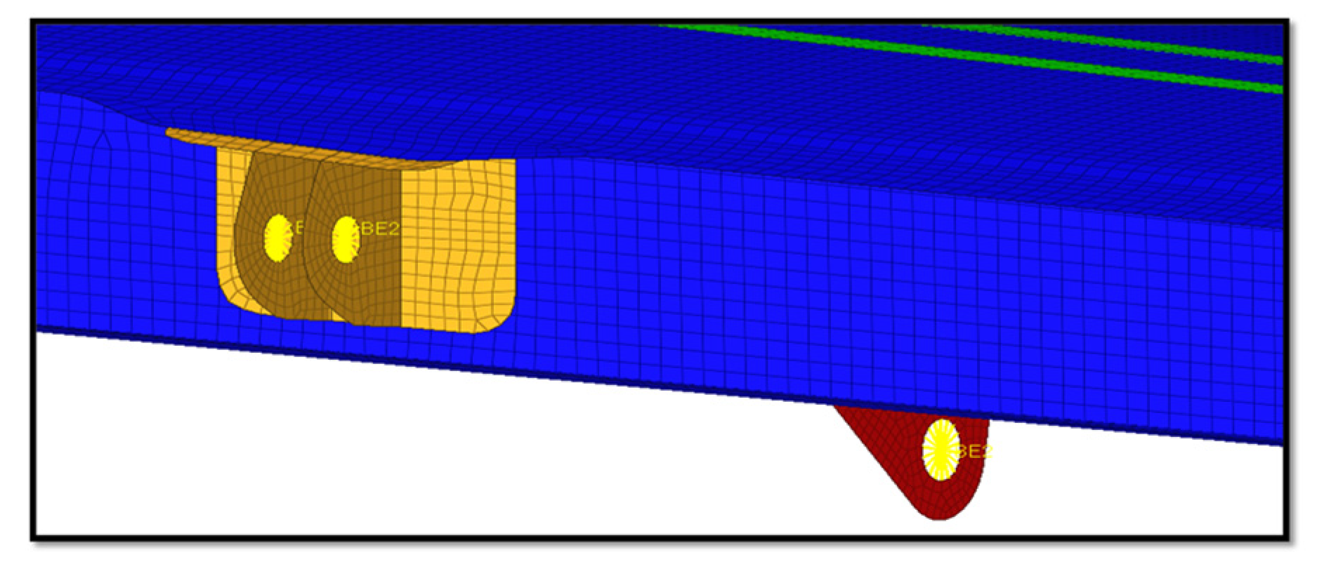
Figure 2 shows a view of the solid model of the wing, without the upper skin to highlight the ribs BL0 and ST225 where the Huth–Schwarmann method was used to calculate the shear and stiffness of fasteners. In
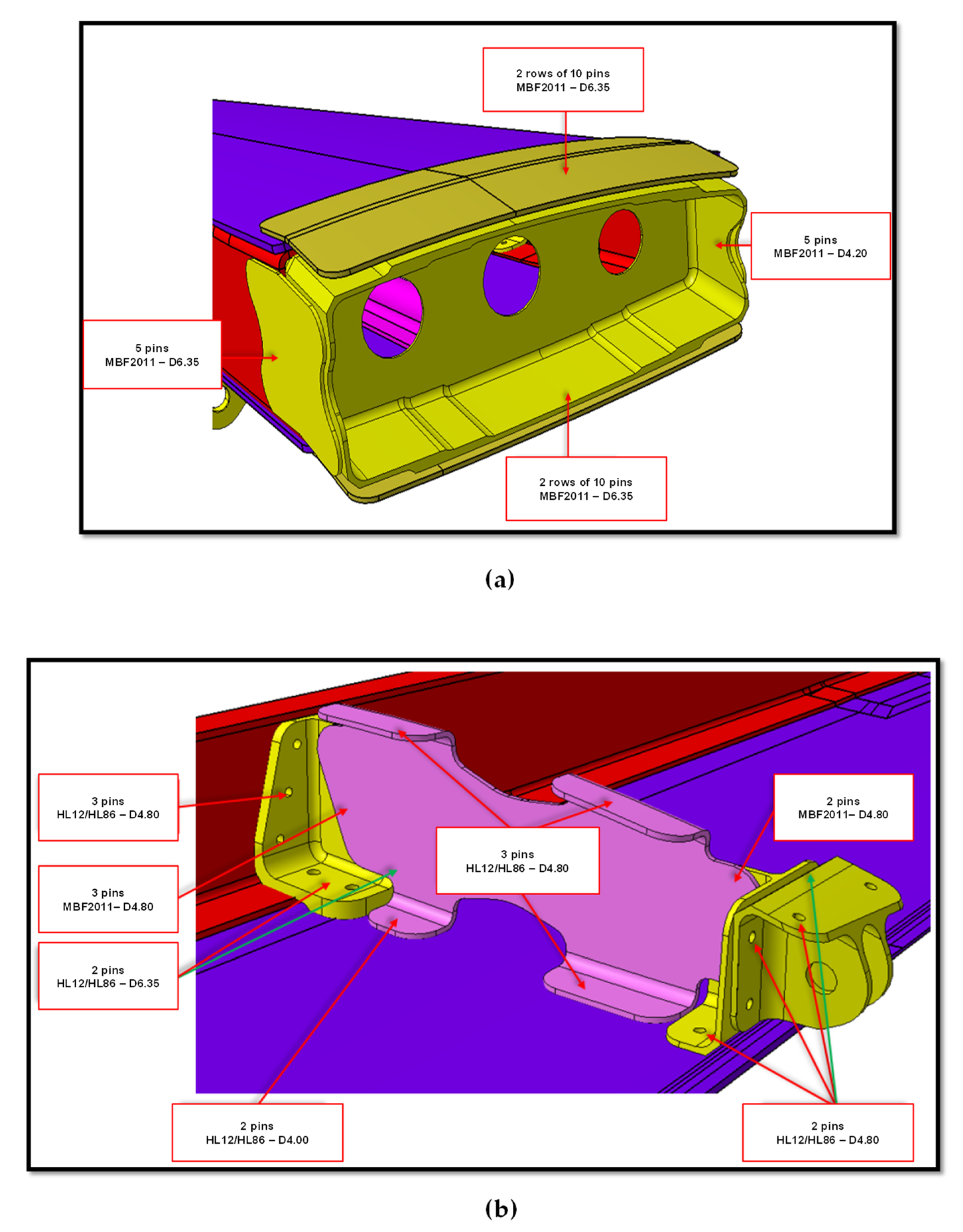
Figure 3, the detail of the ribs BL0 and ST225 connections are given.
In particular, in
Figure 3a, it is possible to observe the Rib BL0 and splices connections. These components, guarantee airfoil shape preservation at the root and allow the transfer of stresses from the skin to the spars.
Figure 3b shows the Rib ST 225 and the fittings for connection to the spars. Finally, in
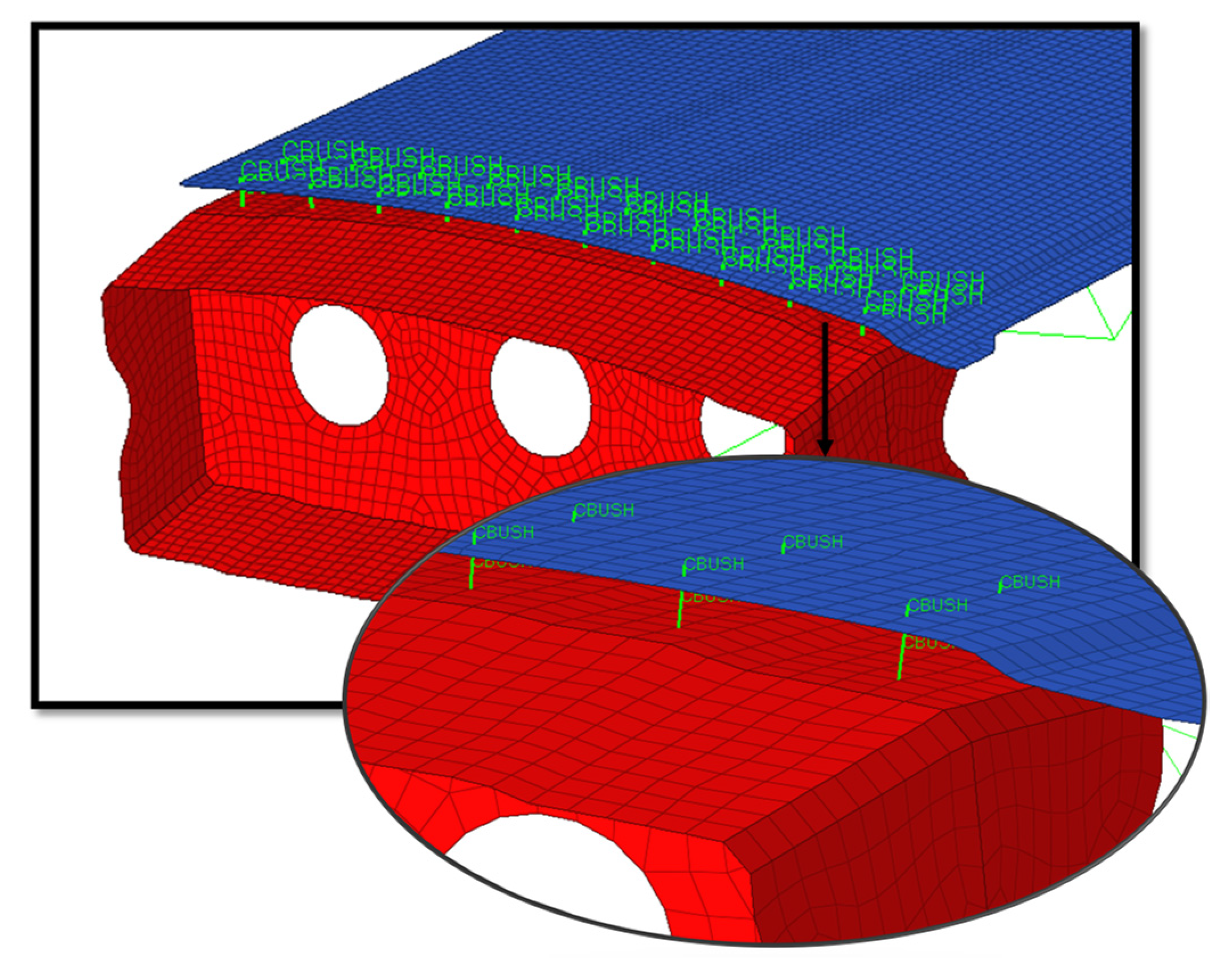
Figure 4, an example of the application of the Huth–Schwarmann method to the Rib BL0 connection is introduced.
2.2. Nodal Constraints
The Multi Points nodal constraints allow to connect nodes and DOFs in an FE model. They can simulate a “rigid connection” or create a “continuous distribution” of the load from one node to another according to their geometric parameters.
Two types of Nodal Constraints can be introduced:
“Single-Point Constraint”, which limits one or more DOFs of a single node;
“Multi-Points Constraints” (MPC) that allow defining the movement of a group of “Slave” nodes, controlled by an equation or a “Master” node.
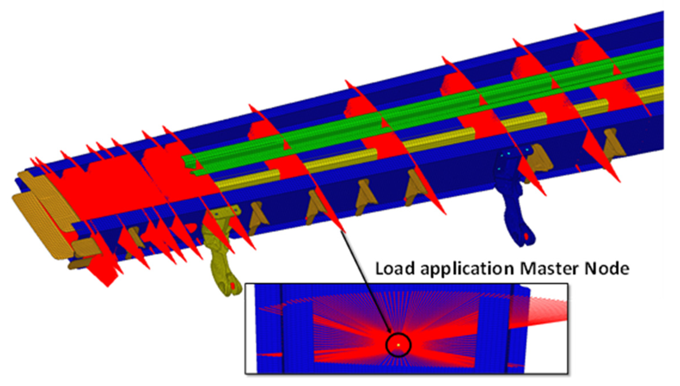
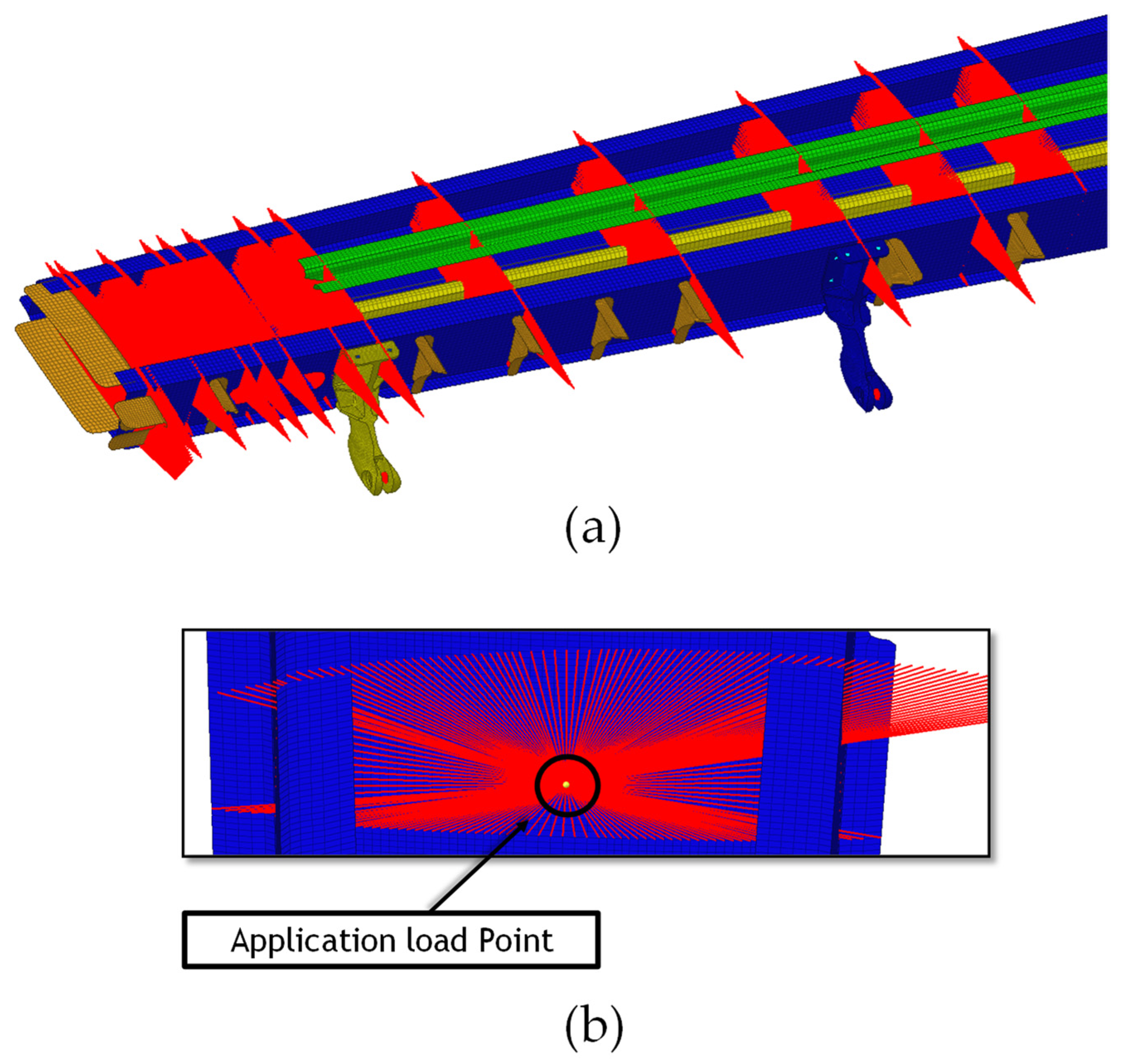
The approach selected in this work employed MPCs. Therefore, by means of MPCs, a rigid coupling between two nodes able to transfer the same translational and rotational deformations from the independent node (Master) to the dependent nodes (Slave) can be simulated. Here, this approach was employed to apply loads (
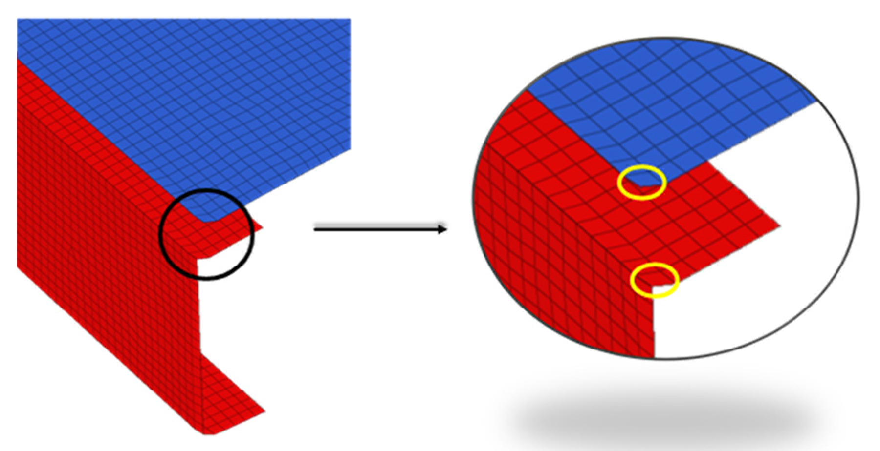
Figure 5) and to connect surfaces with non-coincident meshes, such as that of panels with spars shown in
Figure 6.
2.3. Failure Criteria for Damage Assessment
By performing static analyses in which different failure criteria for both composite and metallic components were included, the structural integrity of the wing was investigated. The failure criteria adopted for composite parts were based on the evaluation of the maximum strain, both in tension and in compression.
The check was performed at the lamina level in the composite laminates for layers oriented at 0°, 90° and 45°. For the Margin of Safety calculation, the following relations were used for tensile, compression and shear margins evaluation at each layer.
where:
e = Maximum Allowable Tensile Strain and Maximum Tensile Strain at Ultimate Load;
e = Maximum Allowable Compressive Strain and Maximum Compressive Strain at Ultimate Load;
e = Maximum Allowable Shear Strain and Maximum Shear Strain at Ultimate Load;
On the other hand, for metallic components, the Von Mises Maximum Allowable Stress compared to the Ultimate Stress
of the discussed metallic alloy was checked for the margin of safety calculation (Equation (10)).
where
is the Von Mises Maximum Stress at Ultimate Load.
2.4. Bearing
The use of fasteners leads to the presence of holes in the components and the resulting localization of stresses, introducing a redistribution of loads within the laminate. High stress concentrations occurring around the holes cause the fasteners regions to be particularly exposed to failure and/or delamination.
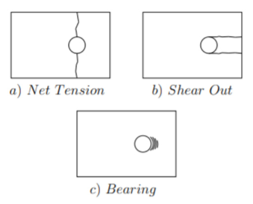
As shown in
Figure 7, failure of the laminate at the fasteners regions usually occurs following three different modes (or a combination of them):
tensile failure;
shear failure;
bearing failure.
The bearing mode of failure depends essentially on geometric parameters, stacking sequence and fibre orientation. Bearing failure usually occurs when the rivet diameter is small if compared to the specimen width. This mode of failure results in the elongation of the hole.
Therefore, a careful study of the Bearing phenomenon is needed when fasteners connections are considered.
To correctly perform this verification, it is mandatory to distinguish between metallic and composite components.
For the metal parts, it is necessary to study the maximum allowable safety factor.
As shown in Equations (11) and (12), the margin of safety is evaluated as a function of the Allowable Bearing Load (
Pbru), the Maximum Bearing Stress (
Fbru), a Fitting Factor (
FF), geometric forming factors (
Dt) and the Bearing Distribution Factor (
θ).
where:
Psh = Shear load acting on the pin;
D = hole diameter;
T = thickness;
Pbru (Allowable Bearing Load) = Fbru × D × t (is the theoretical maximum pressure which can be supported without Bearing failure;
Fbru = Maximum Bearing Stress of the Material (is the theoretical maximum stress which can be supported without Bearing failure);
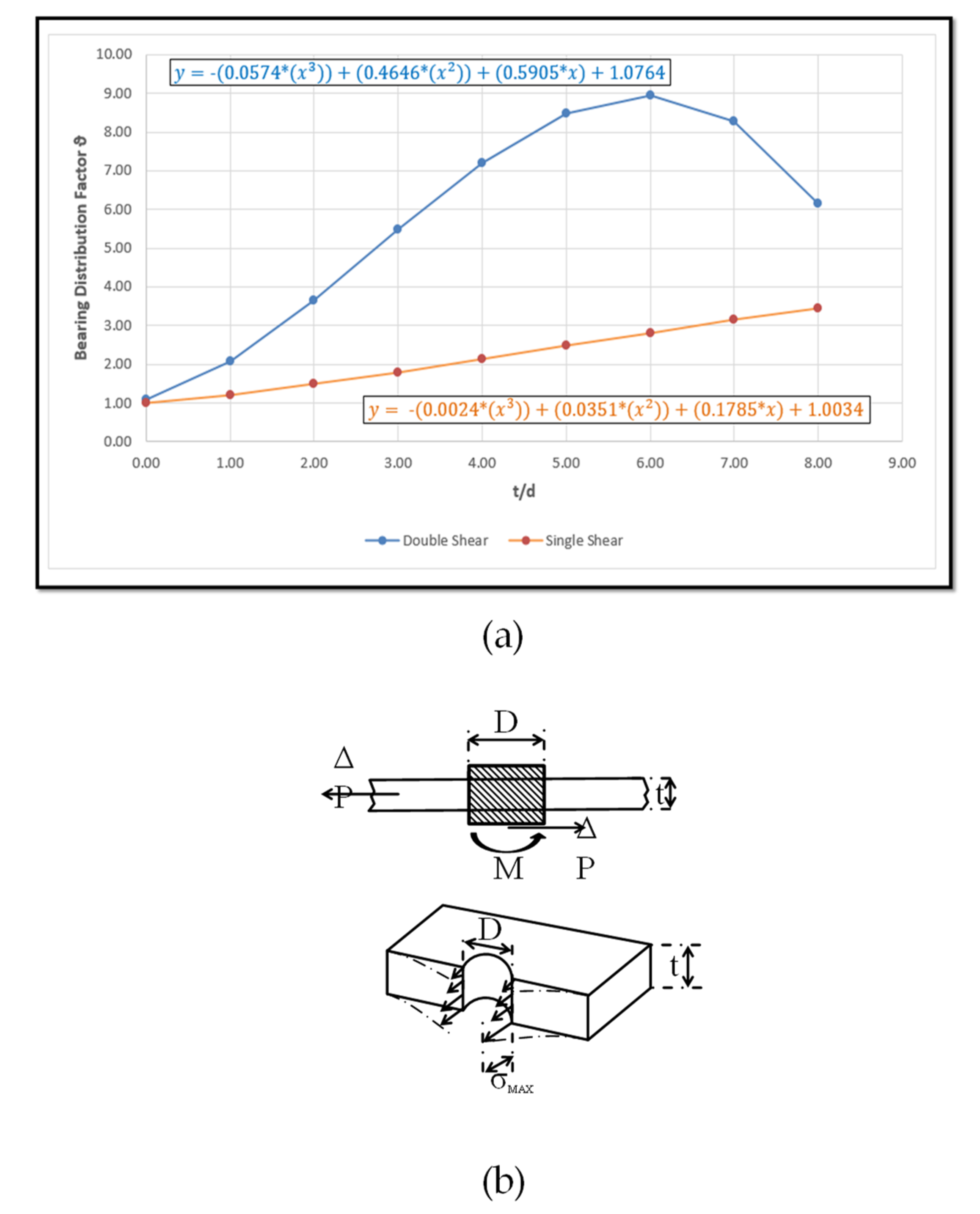
θ = Bearing Distribution Factor (θ takes into account the actual Bearing stress distribution around the hole and is a function of the t/D ratio);
FF = Fitting Factor (a design analysis of structural joints and fittings shall consider a fitting factor of 1.15 to be applied to limit and ultimate the load conditions for all phases of service life.
The fitting factor is used to account for potential variations in internal load paths within the actual structure that are not covered by idealized analytical models. (JSC 65,828 Rev. B, change).
From Equation (12) and
Figure 8, it is clear that the Bearing Distribution Factor takes into account the real distribution of the Bearing Stress around the hole and is a function of the
t/
D ratio. Therefore, it assumes a different distribution for each fastener and differs for single- or double-lap joints discussed in the previous subsection.
To study the maximum allowable safety margin for composite materials, in addition to the parameters considered for the metallic components, the Bearing Strength Variation Factor () has to be considered.
The maximum allowable safety margin for composite materials is then evaluated according to Equation (13).
where, differently from Equation (12), the allowable bearing load ids given by:
Indeed, as extensively illustrated by [
19,
20,
21,
22,
23], differently from metallic configurations, the allowable bearing load depends on the layer orientation. Hence, according to the table in [
22,
23], the Bearing Strength Variation Factor can be considered as a factor taking into account the laminate stacking sequence.
2.5. Linear Buckling
To assess the structural stability under service loads, a linearized buckling analysis was performed. In linearized buckling analyses, a static load is applied to the structure, and the phenomenon is numerically investigated by solving the eigenvalue problem described in the following equation:
where:
= Linear Stiffness;
= Differential Stiffness (load-dependent stiffness)
= eigenvalues (critical loads multipliers);
= eigenvectors (Buckling Modes).
Once the eigenvalues is identified, the critical buckling loads can be calculated by the following Equation (16):
In this equation, , is the applied static load vector.
3. FE Model
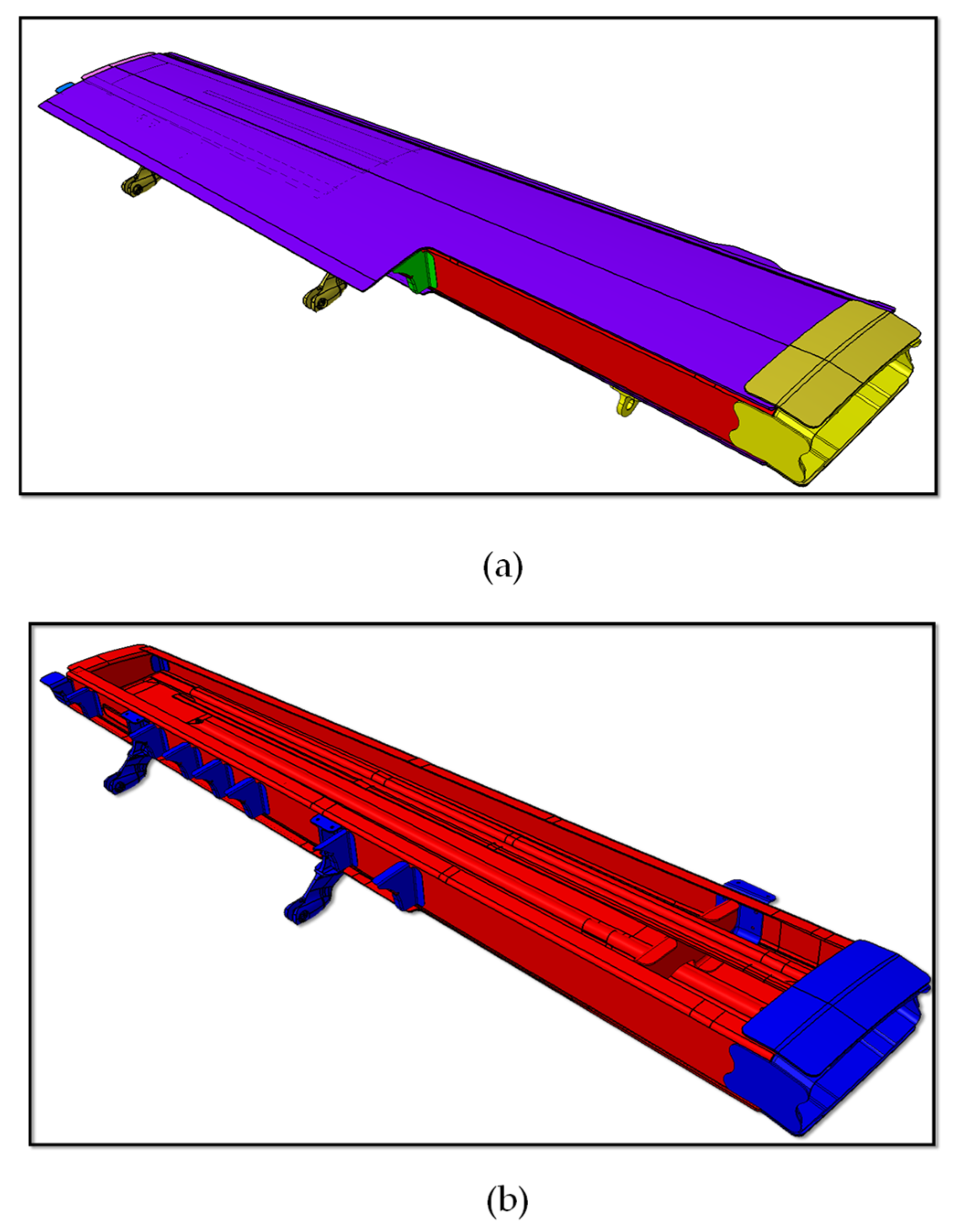
The development of the finite element model started from a preliminary geometry of the full metal wing defined in a CAD project. From this CAD project, the definition of surfaces for shell meshes and of all the geometrical parameters of the composite and metal components of the wing was carried out. The CAD model of the investigated half-wing is shown in
Figure 9a. It consists of 14 components detailed in
Table 1, where the constituent materials are highlighted.
As can be seen from
Table 1, all the primary structural elements were replaced by CFRP IM7/977-2 composite material, whereas mainly the joining components, such as fittings, were still made of metal alloys.
For an immediate detection of the composite and metal components,
Figure 9b shows the half-wing without the upper skin, in which the composite structural components are in red, while the metal components are in blue.
The mechanical properties of the adopted materials are shown in
Table 2 and
Table 3 for the aluminium alloys and in
Table 4 for the composite single layer (0.21 mm thickness)
From the CAD model, by means of the preprocessor software Hypermesh, the middle surfaces of each component were obtained. These surfaces were used as supporting geometry for the definition of a mesh based on shell elements.
To ensure a good quality of the numerical results, sensitivity analyses on the mesh size by applying a unitary flexural load on the investigated wing were performed. At each step, the size of the calculation grid element was halved by developing three different mesh configurations:
Configuration 1: mesh size 10 mm
Configuration 2: mesh size 5 mm
Configuration 3: mesh size 2.5 mm
In comparison to configuration 3, configuration 2 exhibited a 10% lower stress value and, at the same time, a computational time reduction of approximately 50%.
The trivial approach used for the design of the composite component layup for the replacement of metallic components consisted of the following steps:
Thickness extrapolation from the original metal component;
Plies number assignment;
Stacking sequence definition based on stiffness requirements and basic design rules with composites;
FEM analysis verification of component strength and stiffness requirements.
A trial-and-error approach started from a first tentative configuration with final verification by FEM analysis to check the strength and stiffness requirements satisfaction at each iteration. In case of no satisfaction of stiffness and strength requirements, a reformulation of the stacking sequence was performed, and a new design iteration was started. Specifically, three stacking sequences were defined:
Quasi-Isotropic: uniform stiffness in all directions;
Hard (more Plies at 0°)-Resistance for loads across the wingspan;
Soft (more Plies 45°)-Improve Bearing issues for joints.
In the frame of the design iterations, for each composite component, the stacking sequence was switched between the three basic sequences in order to magnify the aforementioned three different structural behaviours.
After performing all the iterations, it was possible to obtain a minimum mass configuration, able to fulfil the required safety conditions. Where possible, a quasi-isotropic sequence was preferred, in order to achieve uniform stiffness in all directions.
However, to enable the transition from one stacking sequence to another on the same component lightening the structure and allowing effective manufacturing through the LRI technology, series of ramps were set up.
These ramps allowed a progressive reduction in the number of plies, with a gradual transition from one sequence to another.
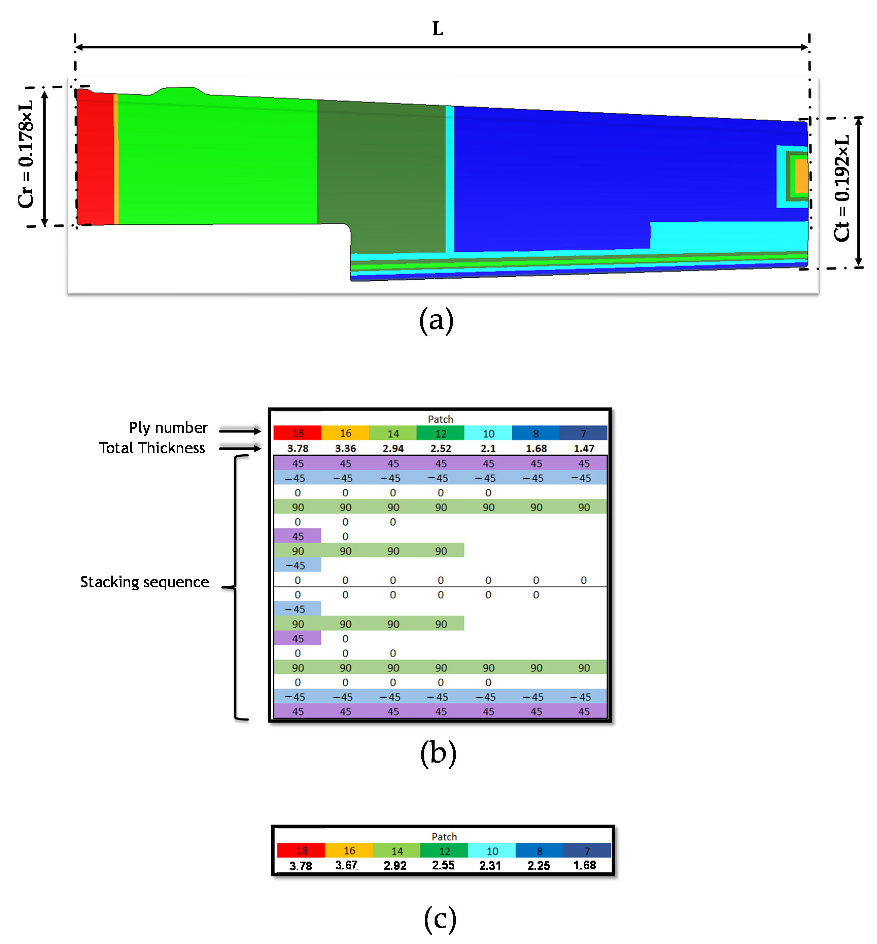
Figure 10a shows the top panel discretized in different colours, representing the different stacking sequences employed, which are detailed in
Figure 10b.
Moreover, in
Figure 10, it is possible appreciate some geometrical information about the examined wing.
In particular,
Figure 10a shows the half-wing span L and the length of the chord at the root and at the tip. Due to company directives, these three parameters are reported as ratio of L.
Figure 10b shows the thickness trend and the stacking sequences of the composite upper wing, highlighting the ramps adopted, and, finally,
Figure 10c shows the thickness trend of the original aluminium upper wing.
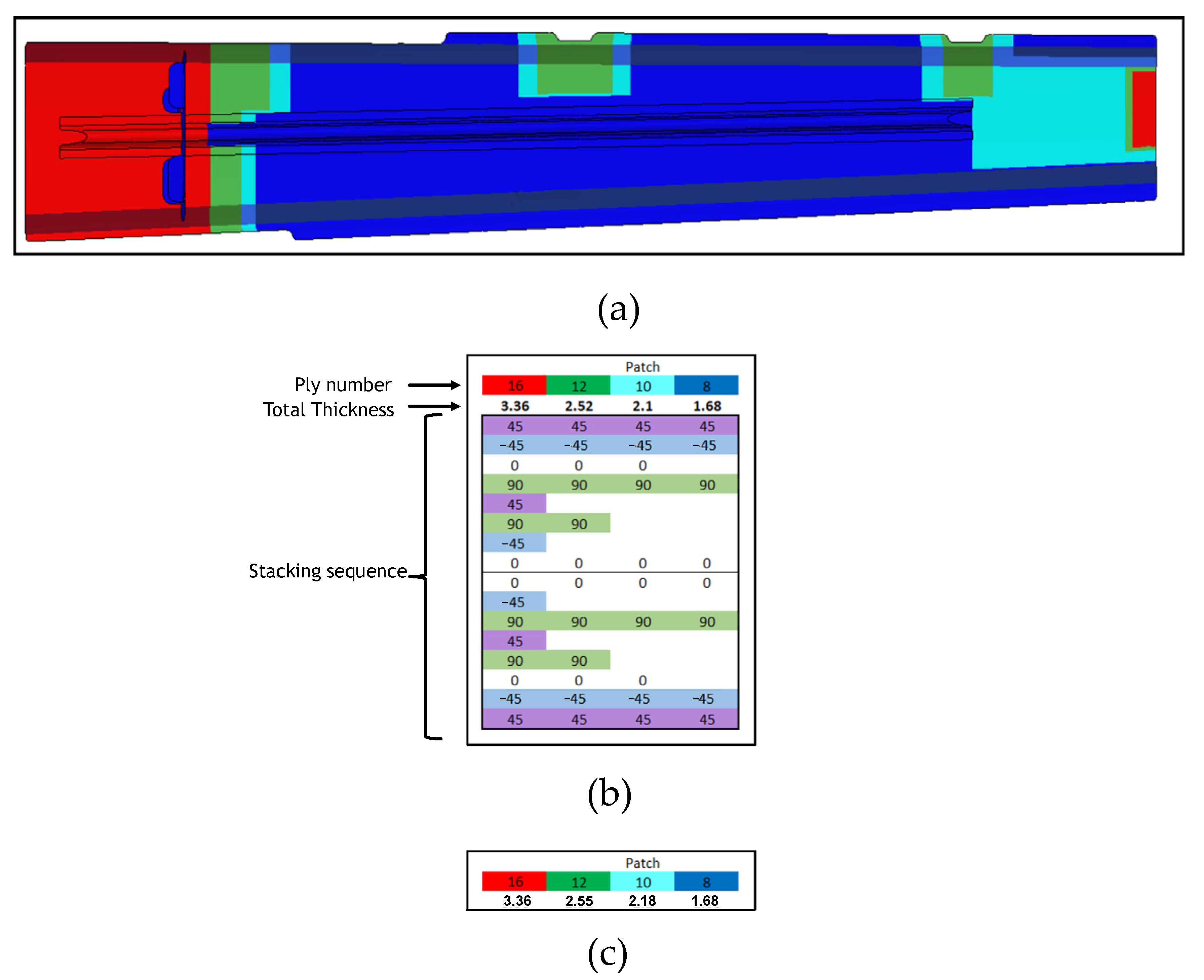
The specifications provided for the upper wing in
Figure 10 are also indicated in
Figure 11 for the lower wing.
It should be highlight that the approach followed, in the frame of this work, for metal replacement with composites, is quite trivial. Actually, this approach allows obtaining weight reduction and comparable stiffness and strengths with respect to metal solutions but does not make use of all the potential of composites structures. Indeed, a real optimization of the stacking sequence should have been performed without considering constraints on the orientation of the layers by adopting, for example, a double concept [
24,
25], bringing to the homogenization of the stacking sequence without the need of symmetry constraints. In this work, the trivial trial-and-error procedure, described above, was preferred due to process and available material constraints on the investigated executive aircraft wing.
For boundary conditions and loads definitions, five different conditions, representative of the most common operating loads, were simulated. As shown in
Figure 5 and
Figure 12, these conditions were applied at 15 different wing stations by using MPCs.
In particular, two loading stations were chosen at the flap interface points, in order to simulate the loads generated by the flaps. The applied load conditions are listed in
Table 5.
As illustrated in
Figure 13, to simulate the connection with the fuselage, nodal constraint conditions were introduced (MPCs) in the fuselage fittings.
4. Numerical Results
In this section the results from the numerical analyses performed on the investigated executive aircraft wing are introduced and commented.
First, the structural integrity was verified by means of numerical linear analysis simulations by performing the following checks:
The composite parts were evaluated in terms of both tension and compression criteria at the layer level for each layer orientation (0°, 90° or ±45°).
The safety margins used to verify the structural integrity are the following:
Subsequently, the following analyses were performed:
Finally, a linear Buckling analysis was performed. In this simulation, through the application of a static load to the structure, which assumed a linear elastic behaviour, it was possible to verify the stability of the structure through the determination of the eigenvalues.
4.1. Failure Criteria Applied to the Composite Components
In this section, the results obtained by applying the failure criteria for composite components are presented.
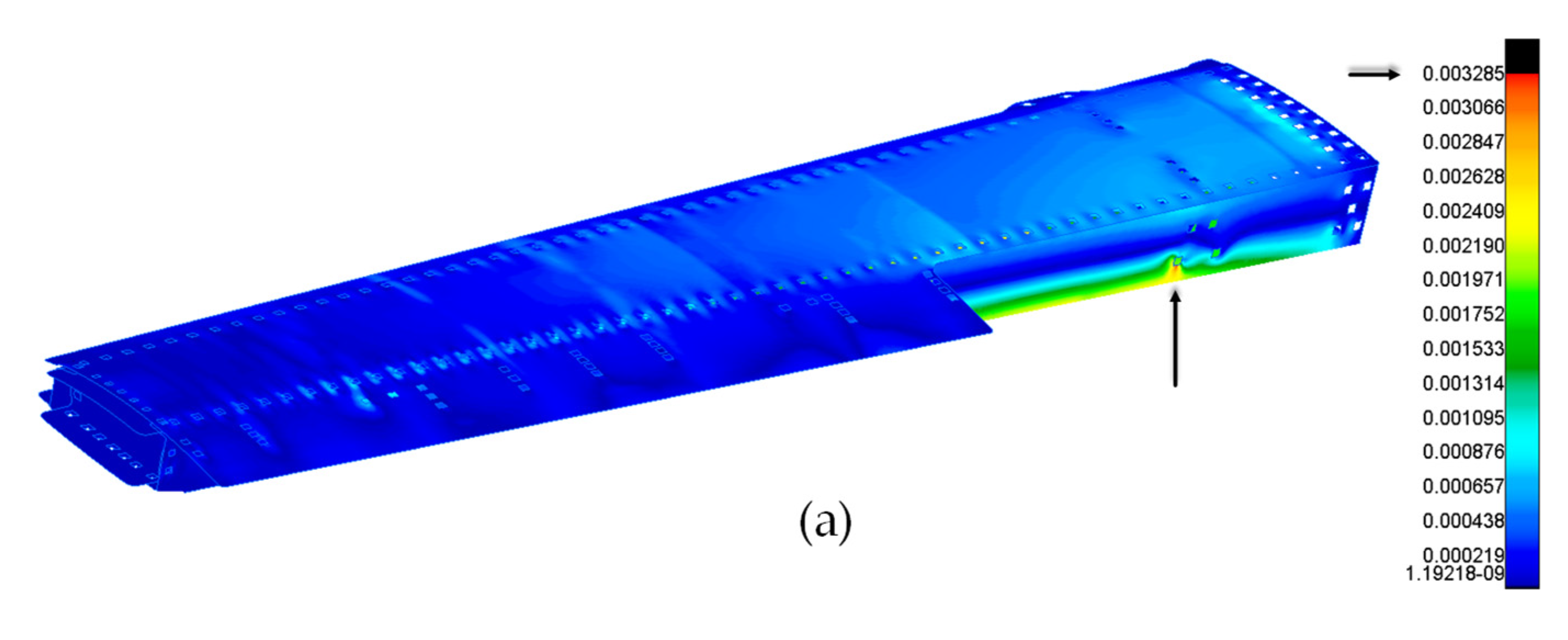
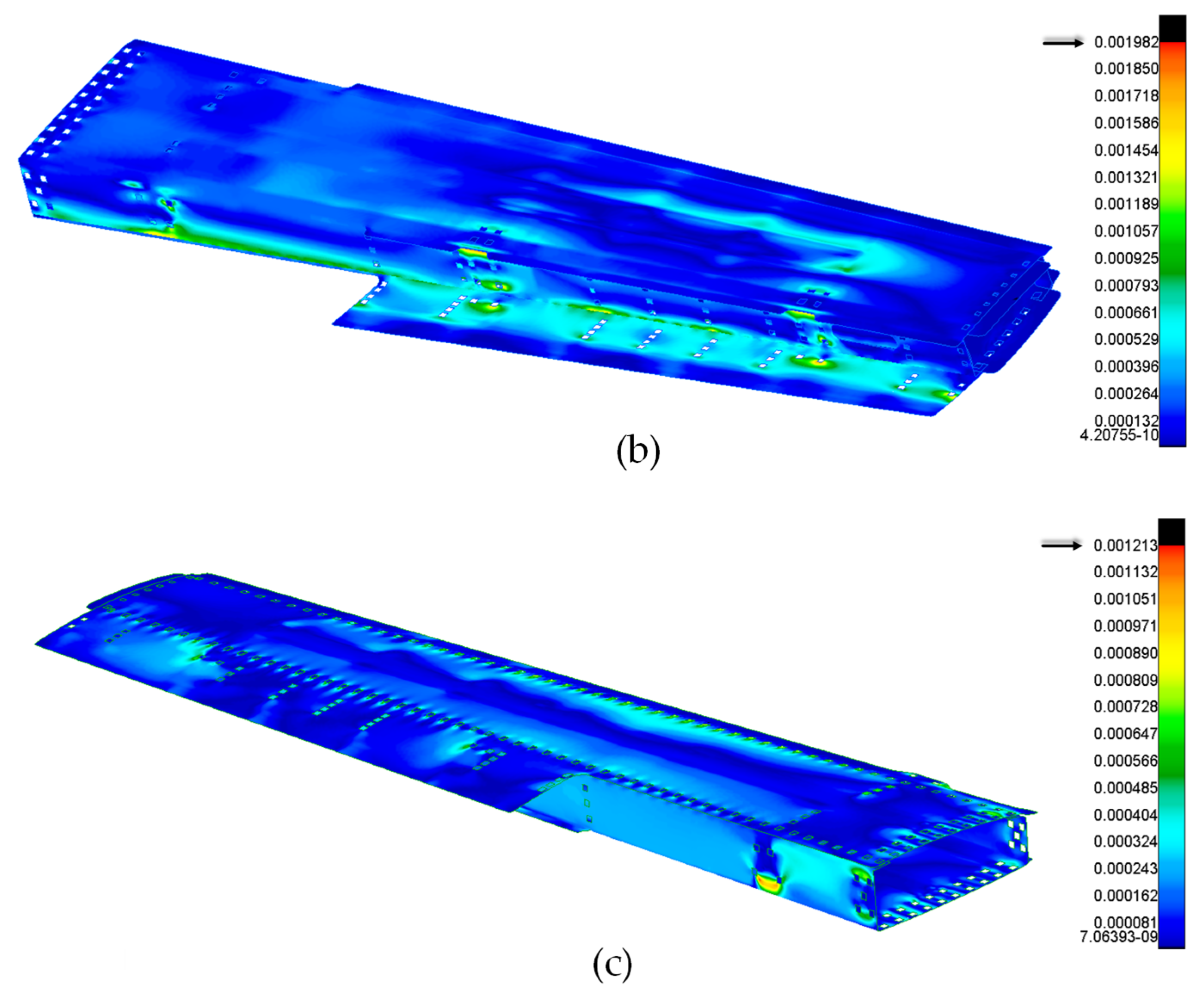
Figure 14 shows the tensile strains produced on the structure in the different layers.
The images shown plot the contour lines obtained as averages of the results of the individual loads applied. This allows an overall view in which it is evident that the configurations examined satisfied the design requirements.
The most stressed area, as can be seen from the results, was found at the connections to the fuselage, resulting from the application of the boundary conditions and the proximity to the constraint. It was possible to satisfy the requirements in this constrained region by introducing modifications to the fittings and to the thickness of the spars, followed by the correct choice of bolts, in the trial-and-error design procedure. The maximum deflection trend was consistent with the expectations and decreased towards the closure rib. As indicated in
Figure 14, strains decreased for plies oriented at 90° and/or ±45°.
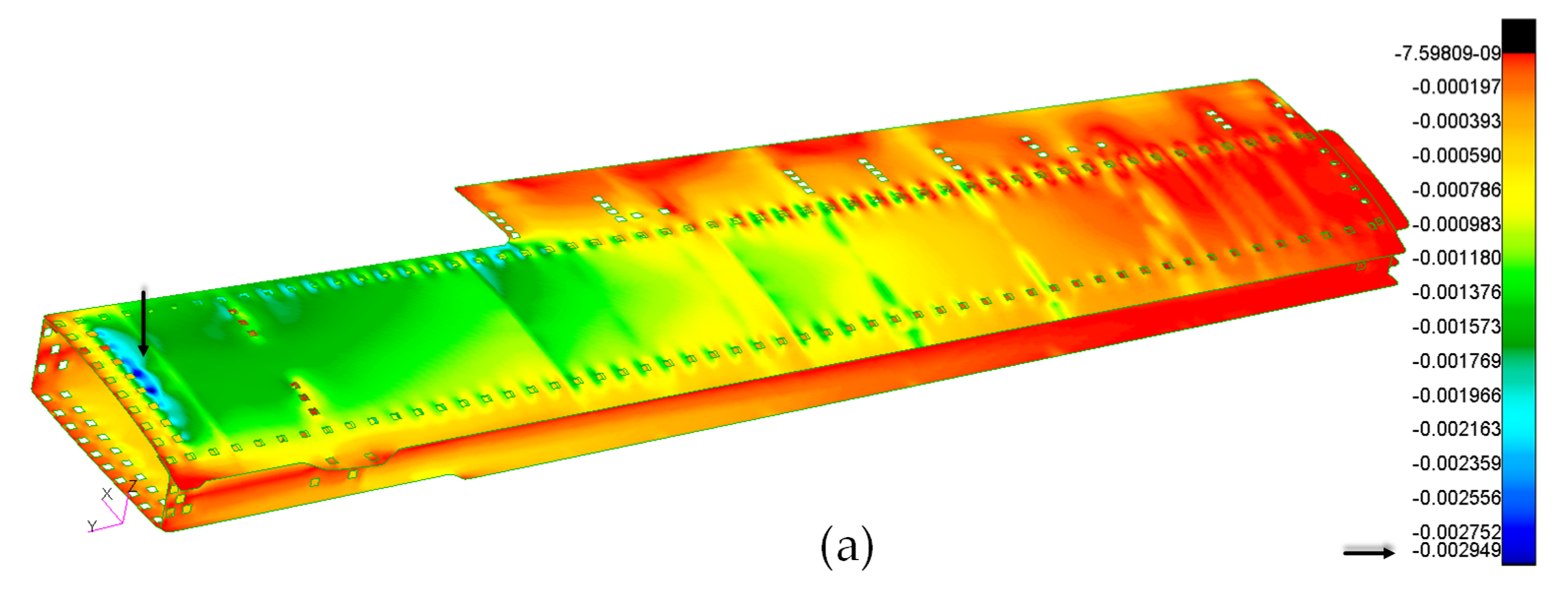
In
Figure 15, the compressive strains produced on the structure are reported. As for the tensile case, images from a combination of the applied loads are shown for the compressive strains for the different layer orientations.
This time, as expected, in addition to the criticalities near the fuselage attachments, the upper skin seemed to be the most stressed component, especially in correspondence of Rib 0, which was compressed in the blue areas. These criticalities were considerably reduced by modifying the layup of the skin in the frame of the trial-and-error design procedure. The skin was reinforced with the addition of further layers and longer ramps near the critical areas.
Comparing the tensile and compressive strains, it is clear that, generally, the most critical conditions were obtained for compression strains.
4.2. Failure Criteria Applied to Metallic Components
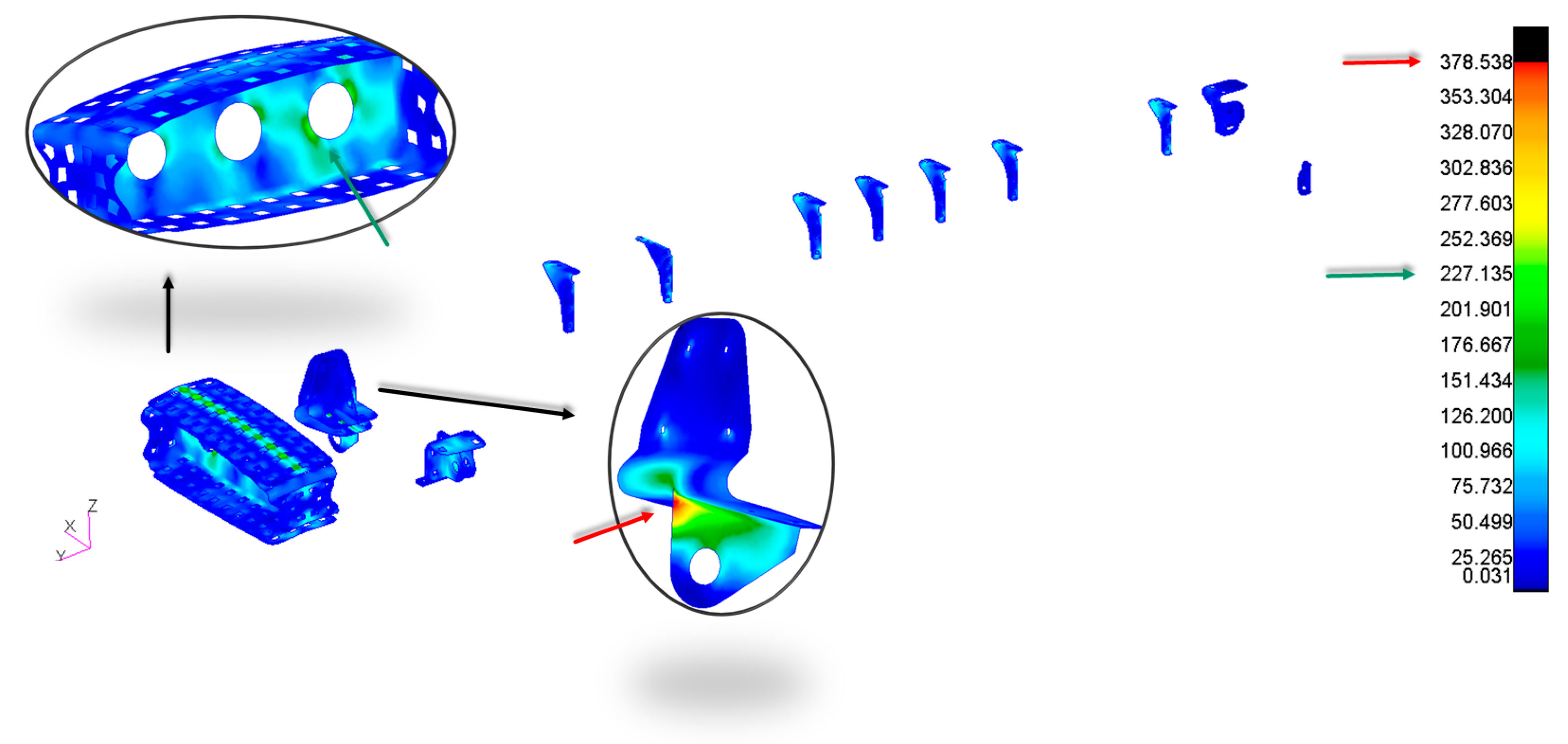
By analysing the Von Mises allowable stress, as illustrated in
Figure 16, it was clear that the metallic components did not exceed the safety margins.
One of the most heavily loaded components was, once again, the fuselage fitting.
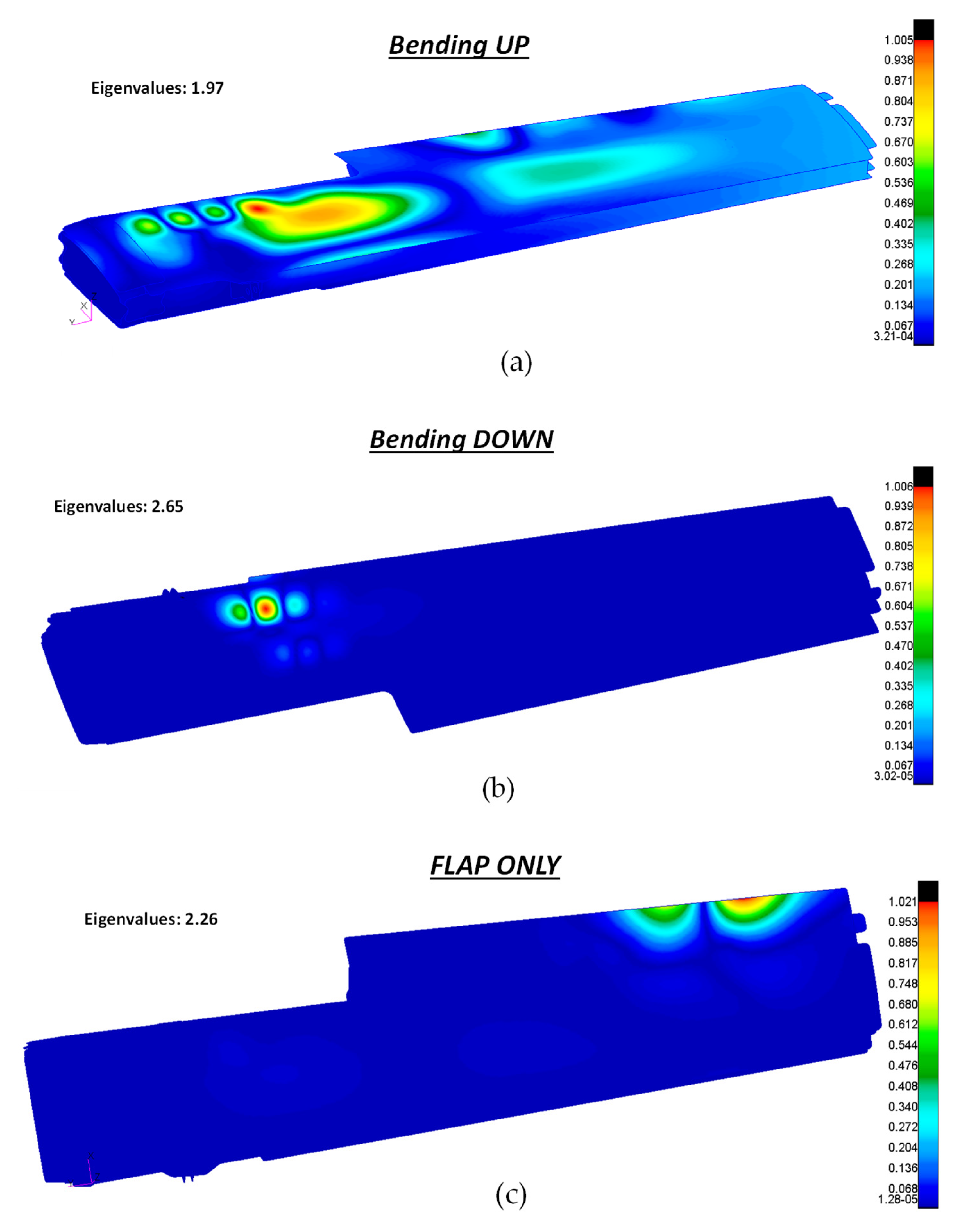
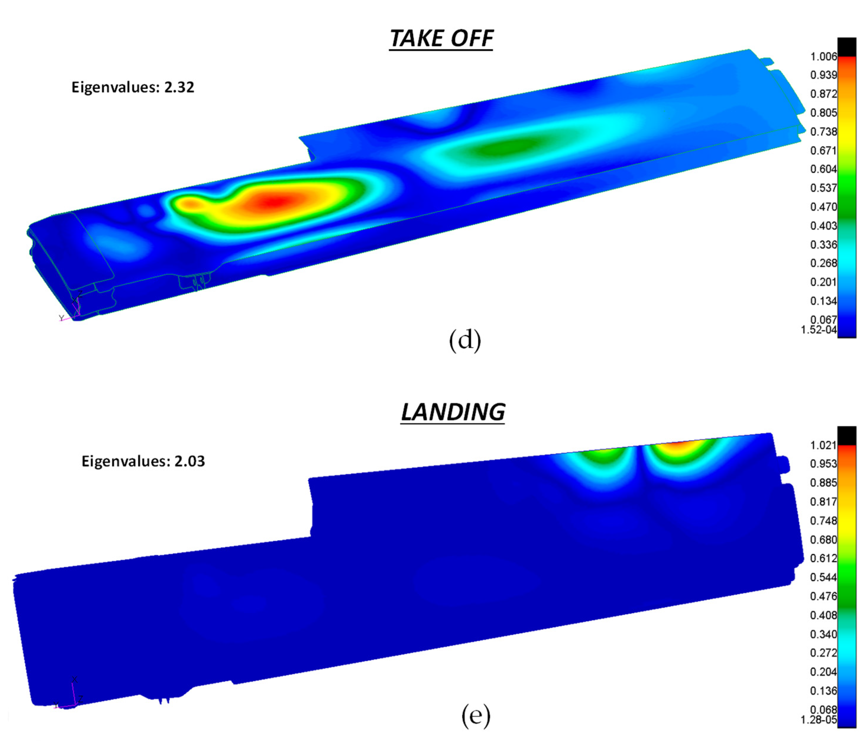
4.3. Buckling Analysis
Linearised buckling analyses were used to check for instability (which can be a critical phenomenon for composite materials under compression) under the five considered loading conditions.
The objective was to derive the eigenvalues, needed to calculate the critical loads, by assuming a linear elastic behaviour of the structure.
The minimum eigenvalue for each load configuration gave information on the percentage of service load needed to bring the structure into instability for each loading condition.
Figure 17 shows the buckling modes and the eigenvalues obtained for each of the five loading conditions defined in
Table 5.
As can be seen in
Figure 17, all eigenvalues were greater than 1 (this means that the service load must be multiplied for the eigenvalue to obtain the first critical buckling load; therefore structural stability was kept under the service load envelope). The most critical condition was the one obtained in the bending up phase, where the eigenvalue assumed the minimum value of 1.97.
4.4. Final Considerations
As seen in the frame of the last subsections, all the stiffness, strength and stability requirements were satisfied by the composite configurations. In addition, the substitution of metal alloy with composites as the primary structural elements of the wing led to a weight reduction of about 33.7% with respect to the full metal wing configuration. This result is very promising because, as already remarked, for this application, a real stacking sequence optimization was not performed. Actually, instead of adopting advanced layup optimization techniques for composites, a trivial trial-and-error procedure was applied due to manufacturing techniques and material constraints. Hence, weight saving can be strongly increased if the constraints on the manufacturing process and on the material are released. This will be the topic of a future research.
5. Conclusions
This work was focused on metal replacement with CFRP composites as primary structural components of an executive aircraft wing. The substitution of metal components with composite manufactured ones, led to a reduction in weight of about 33.7% and satisfied all the requirements in terms of safety margins and structural stability. An advanced numerical Fem model was developed taking into account stiffness, strength and stability constraints by means of a trial-and-error design procedure able to tailor the stacking sequence and to taper the composite laminate to trivially optimise the weight of the resulting wing configurations.
The manufacturing process selected for the CFRP composite was the low-cost Liquid Resin Infusion (LRI) process. The main objective, in a follow-on development on this subject, will be to tailor the manufacturing process in order to perform a one-shot manufacturing run of the wing (i.e., a production of a monolithic component), which will not only drastically reduce the assembly problems, but also allow the repeatability of the component.


 ,
, 


