Article

Investigation of Reynolds Number Effects on Aerodynamic Characteristics of a Transport Aircraft

State Key Lab of Aerodynamics, China Aerodynamics Research and Development Center, Mianyang 621000, China
*
Authors to whom correspondence should be addressed.
Aerospace 2021, 8(7), 177; https://doi.org/10.3390/aerospace8070177
Submission received: 20 April 2021 / Revised: 27 June 2021 / Accepted: 29 June 2021 / Published: 1 July 2021
(This article belongs to the Special Issue Advances in Aerospace Sciences and Technology II)

Abstract

:
The scale difference between the real flight vehicle and the experimental model results in the Reynolds number effect, which makes it unreliable to predict the aerodynamic characteristics of flight vehicles by wind tunnel testing. To understand the mechanism of Reynolds number effects on the aerodynamic characteristics of the supercritical wing that is commonly used in transport aircraft in more detail, surface pressure wind tunnel tests of a transport aircraft reference model with a wing-body configuration were conducted in the European Transonic Windtunnel (ETW) at different Reynolds numbers. There are 495 pressure taps in total equipped on the surface of the test model with the Mach numbers ranging from 0.6 to 0.86 and Reynolds number varying from 3.3 × 10⁶ to 35 × 106. In addition, an in-house developed CFD tool that has been validated by extensive experimental data was used to correct the wing deformation effect of the test model and achieve detailed flow structures. The results show that the Reynolds number has a significant impact on the boundary layer displacement thickness, surface pressure distribution, shock wave position, and overall aerodynamic force coefficients of the transport aircraft in the presence of shock wave and the induced boundary layer separation. The wind tunnel data combined with flow fields achieved from CFD show that the essence of the Reynolds number effect on the aerodynamic characteristics of transport aircraft is the difference of boundary layer development, shock wave/boundary layer interaction, and induced flow separation at different Reynolds numbers.

1. Introduction

The supercritical wing is commonly used in the design of modern transport aircraft by virtue of its excellent transonic performance [1,2,3,4]. The shock wave and the induced separation occur on the upper surface of the supercritical wing during the cruise of transport aircraft, whose properties are significantly affected by the Reynolds number. Flow structures or aerodynamic characteristics of transport vehicles cannot be predicted precisely by wind tunnel tests if the flight Reynolds number is not simulated [4,5,6]. Two well-known examples of transonic Reynolds effect phenomena are the ill-estimated aerodynamic characteristics of C-141 aircraft and C-5A aircraft. The low Reynolds numbers obtained in C-141 wind tunnel tests led to a huge difference in aerodynamic center location from the flight tests. The drag divergence Mach number of C-5A aircraft obtained from the wind tunnel test was 0.02 lower than that obtained in flight. The ill-estimated shock position and pressure distribution in low Reynolds number wind tunnels introduce significant risk to the success of the vehicles [7,8,9]. Large-scale industrial cryogenic wind tunnels like the National Transonic Facility (NTF) [9] in the USA and European Transonic Windtunnel (ETW) [10,11] in Germany provide a unique test capability to match the free flight Reynolds number of modern transport aircraft. However, it is unfeasible to conduct all tests in cryogenic wind tunnels due to their high costs and relatively low efficiency. Therefore, for a considerable period, the traditional wind tunnel will continue to be the dominant ground test facility for the development of transport aircraft.
To scale the test data obtained from traditional wind tunnels to free flight, the mechanism of Reynolds number effects on aerodynamic characteristics of flight vehicles should be understood. Elsenaar [12] discussed the variation of airfoil and high aspect ratio wing aerodynamic characteristics (lift, pitching moment, drag, drag divergence, and buffet boundaries) as a function of Reynolds number based on wind tunnel results and summarized that the Reynolds number effects could be categorized into direct and indirect Reynolds number effects. The direct Reynolds number effects are the ones associated with a constant pressure distribution while the indirect Reynolds number effects are associated with a change in pressure distribution for varying Reynolds number. Based on the NTF cryogenic wind tunnel facility, Curtin et al. [8,13] investigated the impact of Reynolds number on a Boeing 777 and compared the full-flight Reynolds number wind tunnel data to that from free flight tests. The experimental results showed that the drag and the cruise angle decreased, and the drag divergence Mach number increased with the increase of Reynolds numbers. Additionally, the comparison of aerodynamic data from flight tests and data from the cryogenic wind tunnel were in good agreement, but the CFD and wind tunnel correlation was not very satisfying. Clark, R.W. and Pelkman, R.A. [14] from The Boeing Company tested an advanced transport aircraft wing in the NTF facility at Reynolds numbers of 6, 30, and 40 million. They found that the aft loading on the airfoil sections increases due to the reduction in viscous “de-cambering” caused by the presence of the wing boundary layer as the Reynolds number increases, which would lead to an increased nose-down pitching moment. However, the further increase to 40 million results in a significant increase in pitching moment as the outboard wing is unloaded due to the aeroelastic effects. Several other references [15,16,17] can also be found, which investigated the Reynolds number effects on transport aircraft. However, generally speaking, high Reynolds number wind tunnel results and the extrapolation techniques related to the aerodynamic characteristics of Reynolds number effects of transport aircraft have seldom been published, as they provide significant cost and time advantages over a competitor. For providing more detailed and accurate experimental data to investigate the mechanism of Reynolds number effects on aerodynamic characteristics of the transport aircraft and develop Reynolds number effect extrapolation techniques, a transport aircraft model with a typical supercritical wing was tested in an ETW facility at Reynolds numbers of 3.3, 6.6, 15, 25, and 35 million. Wing deformation was measured using the stereo pattern tracking technique [18,19] to evaluate the pseudo-Reynolds number effect caused by aeroelasticity of the large aspect ratio wing. The influence of transition mode (free transition and fixed transition) was also investigated.
On the other hand, numerical simulation can complement wind tunnel testing and enable thorough investigation of flow topology and the corresponding Reynolds number effect mechanism. A number of studies on Reynolds number effects on aerodynamic characteristics of transport aircraft have been conducted numerically [20,21,22,23,24,25,26]. Yuma Fukushima et al. [21] conducted wall-modeled large-eddy simulations at realistic high Reynolds numbers (Rec ≈ 107) to investigate the Reynolds number effect on the flow fields of a supercritical airfoil. The authors also investigated CFD methods for predicting the Reynolds number effects of supercritical airfoil [26,27]. However, it is still challenging to predict the Reynolds number effects of three-dimensional supercritical wings and transport aircraft. Karl Pettersson et al. [28] conducted CFD calculations by solving the RANS equations on an unstructured grid for a transport aircraft with and without twin sting booms at different Reynolds numbers. It was concluded that the pitch-up moment would have to be corrected as a function of Reynolds number in order to estimate free flight conditions. However, their study focused on the Reynolds number effect trends and the influence of the twin sting boom. The mechanism of Reynolds number scaling effects on aerodynamic characteristics was not analyzed. Several RANS solvers, such as object-oriented software elsA of ONERA and unstructured RANS Solver TAU from DLR were developed for accurately predicting lift, drag, and moments of transports aircraft [29,30]. However, most previous CFD studies focused on how to improve the predicting accuracy of aerodynamic properties of transport aircraft. Systematic studies of Reynolds number effects on aerodynamic characteristics of the transport aircraft and their corresponding mechanism are limited in public literature.
In this paper, an in-house developed CFD tool that has been validated by extensive experimental data is used to correct the wing deformation effect [31] and achieve the detailed flow structure over the transport aircraft model. Closely combining with cryogenic wind tunnel test results, the Reynolds number scaling effects on aerodynamic characteristics of transport aircraft and their mechanism are analyzed in this paper. The detailed model configuration and the corresponding experimental and numerical setups are introduced in Section 2. Thereafter, Reynolds effects on the surface pressure distribution, shock wave location, trailing edge pressure recovery, boundary layer characteristics, and aerodynamic coefficients of the supercritical wing are discussed systematically based on the wind tunnel results and numerical flow structures in the case of the Reynolds number ranging from 3.3 × 10⁶ to 35 × 106. These results are beneficial to understanding the mechanism of Reynolds number effects of transport aircraft, which are briefly analyzed in this paper and also are conducive to developing Reynolds number effect extrapolation techniques, which is the priority of our next research.

2. Wind Tunnel and Experimental Setup
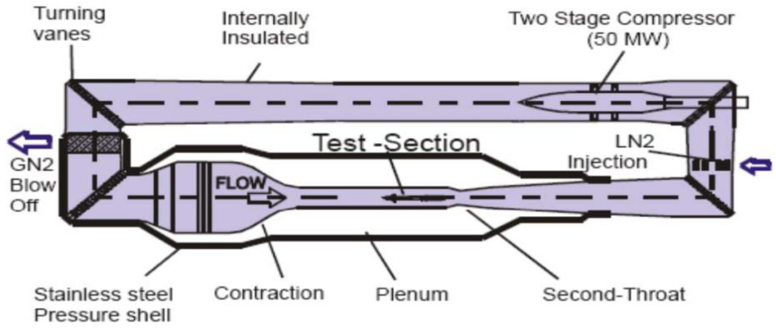
2.1. Wind Tunnel

The tests were conducted in the European Transonic Windtunnel (ETW). The ETW facility (Figure 1) is a high Reynolds number transonic wind tunnel adopting nitrogen as the test gas. High Reynolds numbers can be achieved by testing at cryogenic temperatures down to 115 K and at pressure levels ranging from 115 up to 450 kPa. The Mach number of this wind tunnel ranges from 0.13 through the high subsonic speeds representative for cruise conditions of modern transport aircraft, up to 1.3 for supersonic aircraft or space vehicles. The test section size in conjunction with the available pressure and temperature ranges represented the best combination of parameters to achieve, with full span models (spans up to 1.56 m), a Reynolds number of 50 × 106 at cruise conditions, and up to 90 × 106 with vertically mounted semi-span models.

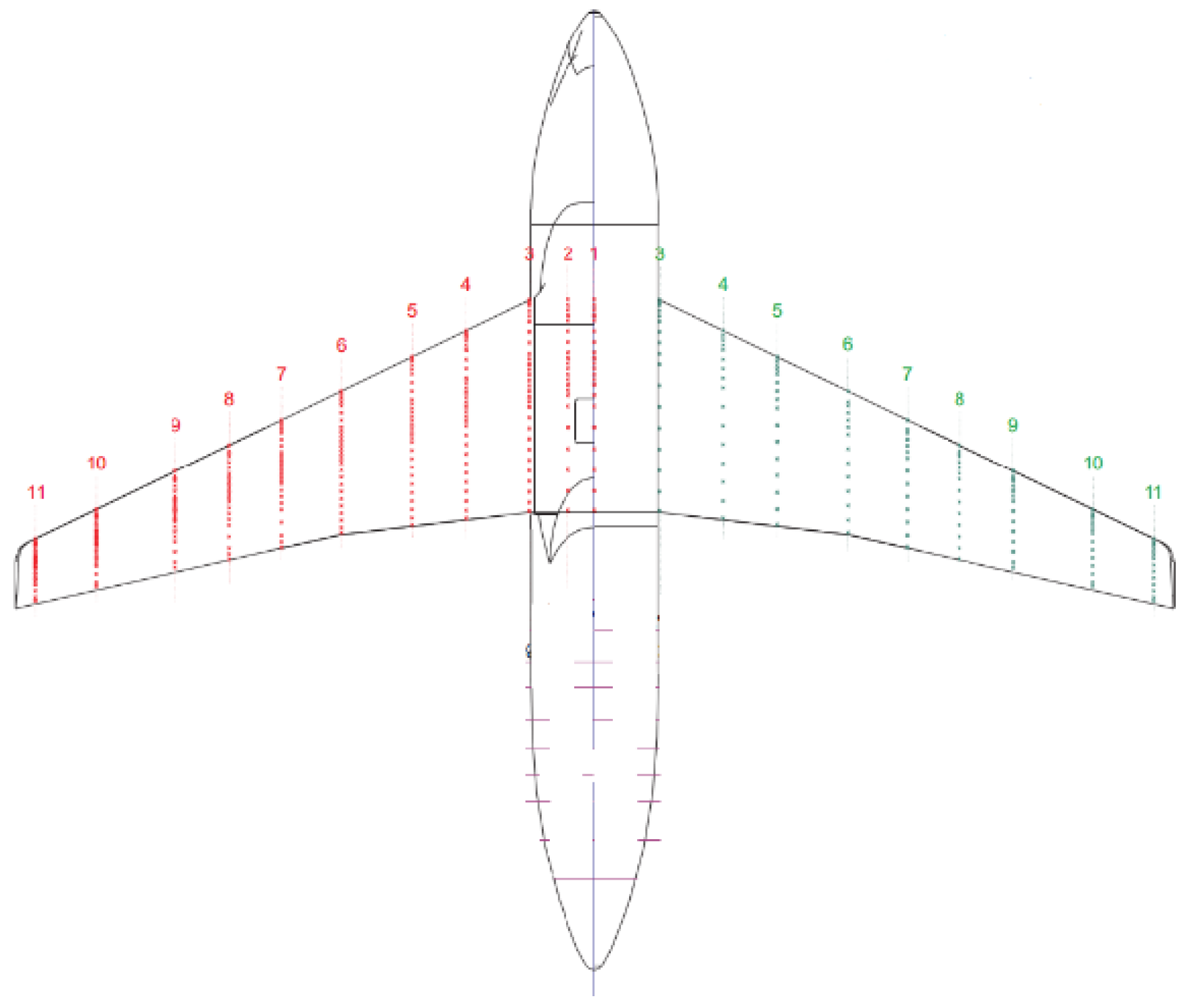
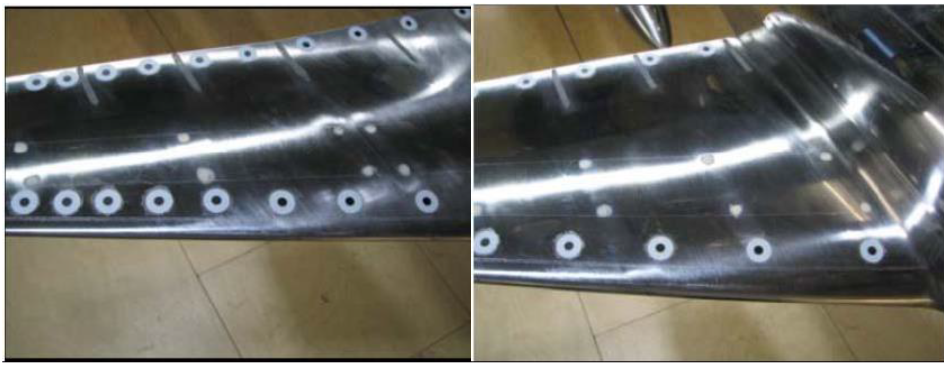
2.2. Model Configuration and Test Campaigns

As shown in Figure 2, a transport aircraft reference model with a wing-body configuration was adopted. The supercritical wing with a 25-degree leading edge sweep has a taper ratio of 0.28. The test model is made of maraging steel 200, a metal material applicable in cryogenic conditions.
There are 495 pressure taps in total equipped on the surface of the test model, among which 18 pressure section taps with 416 pressure orifices were distributed along the supercritical wing full span. There are 9 pressure sections located on the upper surface of the port wing, and the other 9 are located on the lower surface of the starboard wing. The boat tail of the transport aircraft test model is equipped with 79 orifice taps for evaluating the Reynolds number effect on flow properties over the boat tail. Pressure taps are connected to the PSI8400DTC electronic scanning valve system. The accuracy of the surface pressure measurement system is in the range of 100–200 Pa depending on the range of the pressure scanner used (45, 30, 15 psi). The pressure scanners were referenced to the base pressure that was measured in the sting boss with an accuracy of around ±100 Pa. In practice, the accuracy obtained for the pressure scanners is the combination of the base pressure and pressure scanner accuracy, which was examined during check calibrations before each test block and was found to be better than ±250 Pa.
The balance and model misalignment, model dead weight, and the model elastic angle under aerodynamic forces are all corrected. The test Mach number varies from 0.6 to 0.86, and the Reynolds number ranges from 3.3 million to 35 million.
The surface pressure coefficient is calculated by
C p i = p i p q , i = 1 , 2 n
Aerodynamic force and moment coefficients of test model are obtained by pressure coefficient integration:
C n = C p d x C a = C p d y C L = C n cos α C a sin α C m , c / 4 = ( x ¯ C p d x ¯ + y ¯ C p d y ) ¯ 1 4 C p d x ¯
To evaluate the influence of boundary layer transition fixing on Reynolds number effects, Ballotini grit strips with diameters from 0.075 to 0.09 mm were attached at the position of 7% local chord on the upper and lower wing surface in the case of Reynolds number lower than 15 × 106. The supercritical wing was tested without the roughness band when the Reynolds number is higher than 15 × 106. During the whole wind tunnel test campaign, Ballotini grit strips with diameters from 0.1 to 0.125 mm were attached to the model fuselage 25 mm away from the fuselage nose for transition fixing. The grit size and distribution were determined according to the ETW standard wind tunnel procedure and criterion. Typically, grit strip height and grit density are 2 mm and 4%, respectively. The grit strip is stuck at the position of 7% local section chord along the wingspan and at the position of 10% model body length from the nose.
To evaluate the wing deformation effect and obtain a pure Reynolds number effect, an SPT system of ETW with a sampling frequency of 5 Hz and a sampling cycle of approximate 8 s was applied to measure the wing deformation. As illustrated in Figure 3, 40 markers were attached along the wing surface with a sparse distribution near the wing root and with increasing density toward the wing tip. SPT images were recorded at each angle of attack. Then, the marker recognition and corresponding displacement calculation were conducted via specialized software.
In practice, wing cross-section was assumed to be a rigid body, and the wing deformation was usually twist and bending. Twist angle θ and bending deformation Δz in local coordinate system would be calculated as follows:
[ x d z d ] = [ cos θ sin θ sin θ cos θ ] [ x 0 z 0 ] + [ Δ x Δ z ]
In the above formula, x0, z0 and xd, zd represent the coordinate values of the feature points on the section before and after the wing deformation. The accuracy of ETW SPT system was 0.1° and 1 mm.
Wing deformation effect is corrected with CFD technique after the wing configuration has been reconstructed according to SPT measurements.

3. Computational Setup

3.1. Computing Platform and Simulation Methods

In-house developed computational fluid dynamics software was used to evaluate and correct the wing deformation effects and investigate the detailed steady flow structures over a large range of Reynolds numbers. The central, ROE, and LU-SGS schemes were adopted to discretize the convective, viscous, and time items, respectively, for the finite volume flow solver. A non-reflective boundary condition was used as the far-field boundary condition. All aircraft surfaces were dealt with as no-slip viscous boundaries.
Numerical results obtained by several common turbulence models, including the one-equation Spalart–Allmaras (SA), two-equation k-ε, and two-equation SST models were compared with experimental results obtained from wind tunnel tests. Overall, simulation results based on the k-ω SST model have better correlation with the experimental results, especially for predicting the shock wave strength and position. Therefore, turbulence closure in the present study is given by the k-ω SST model.

3.2. Grid Generation

Multi-block structured grid technology was applied to generate the grids of the surfaces, inner field, and far field. The viscous boundary layer regions were resolved with y+ ≈ 1. To verify the mesh dependency, 4 sets of grids were generated with the same y+ and O-H topology. Table 1 presents the parameters of the 4 sets of grids. By comparing the aerodynamic coefficient convergence curves of the 4 sets of grids, only the coarsest mesh (2 M) does not run to monotonic convergence and the densest mesh (20 M) has the best gird convergence. However, considering the results of medium grid (10 M) were close to the convergence solution and can meet the requirements for engineer application with much less calculation amount, the medium mesh (10 M) was used in the current study.

4. Results and Discussion

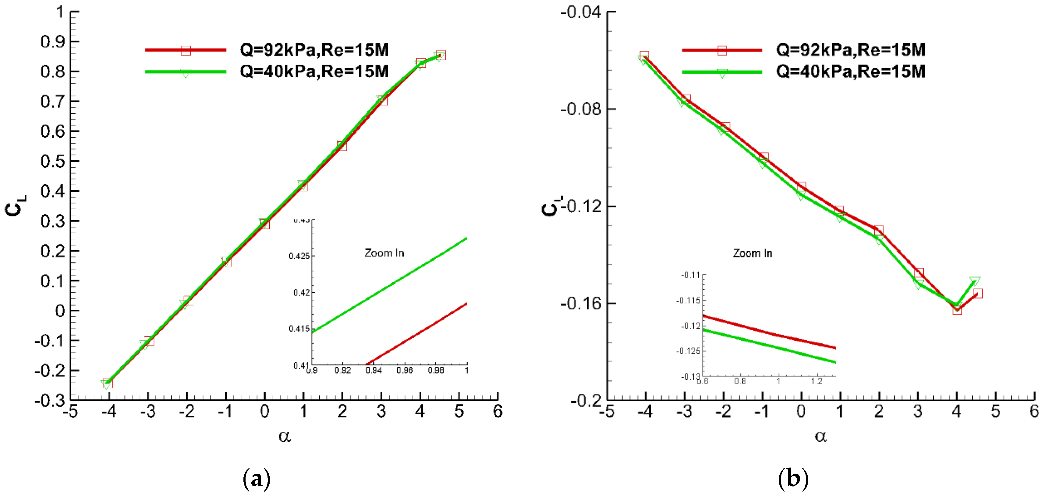
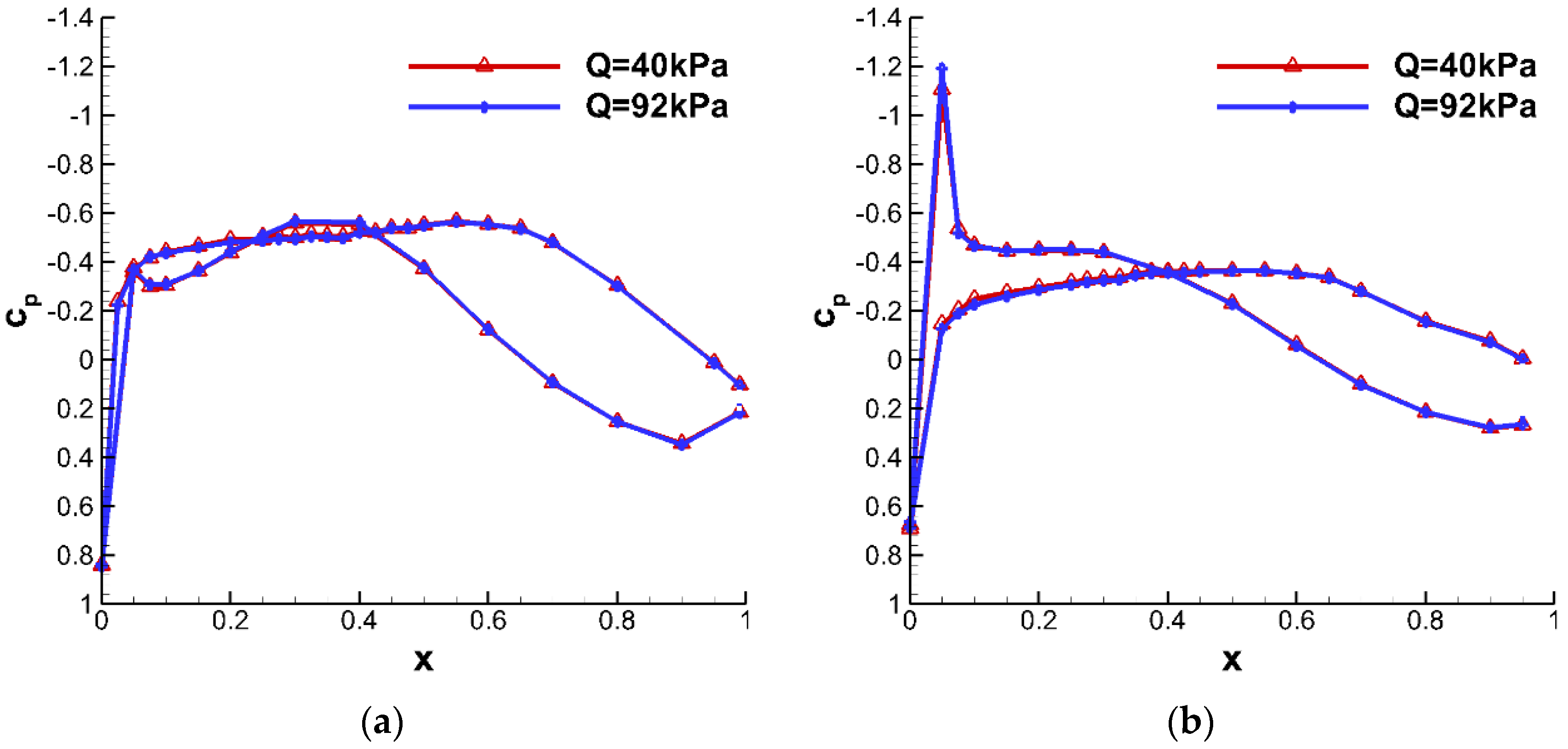
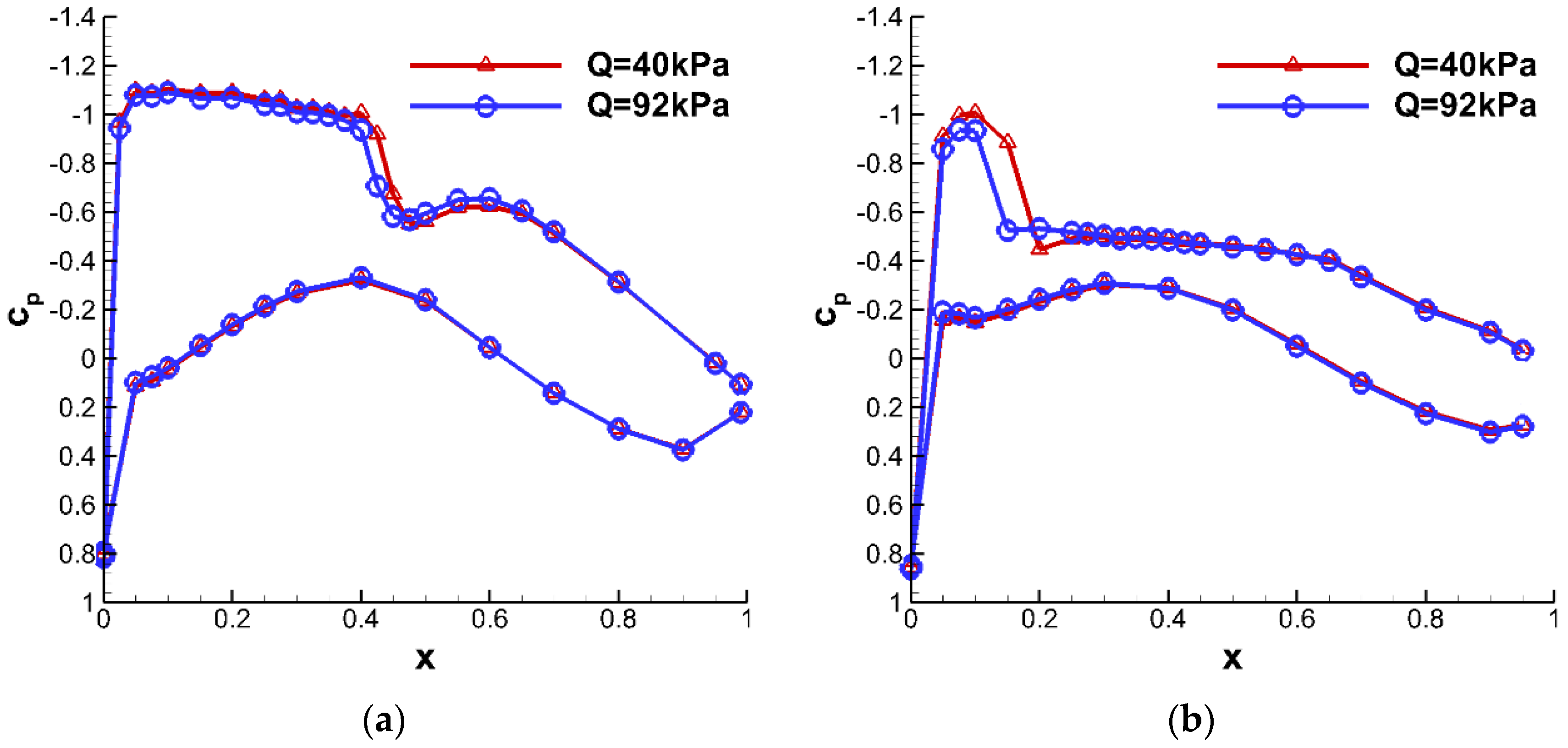
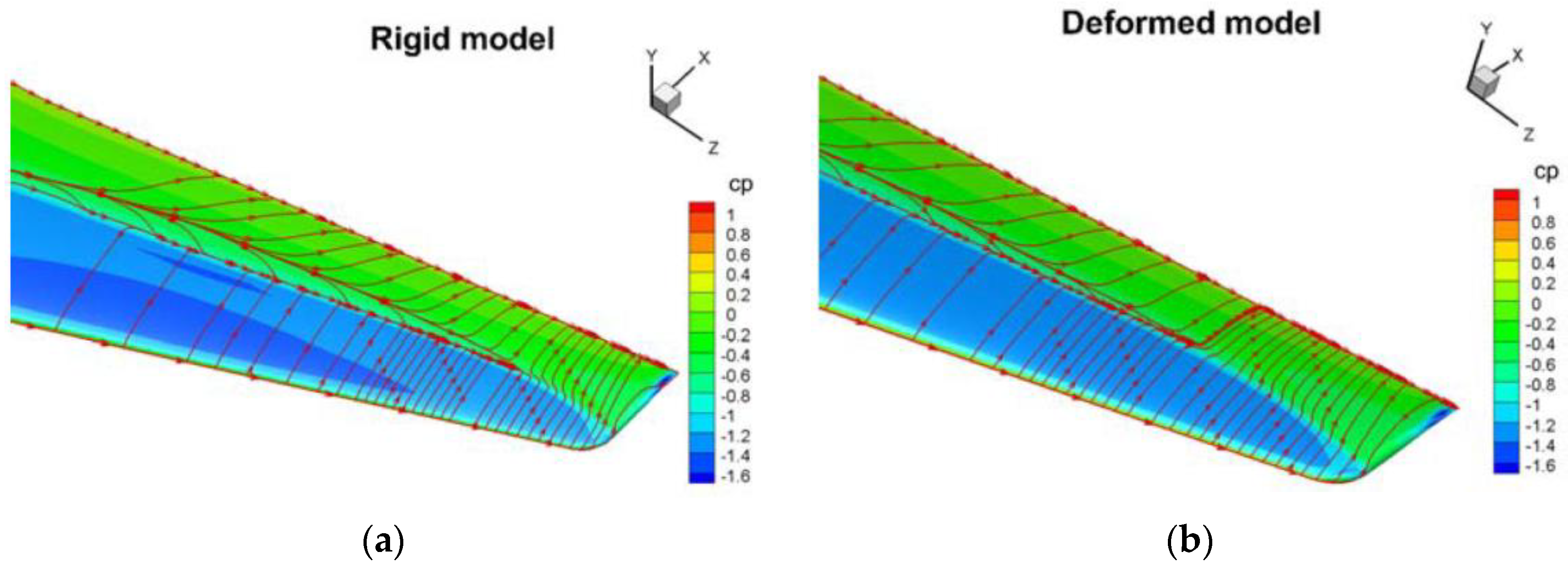
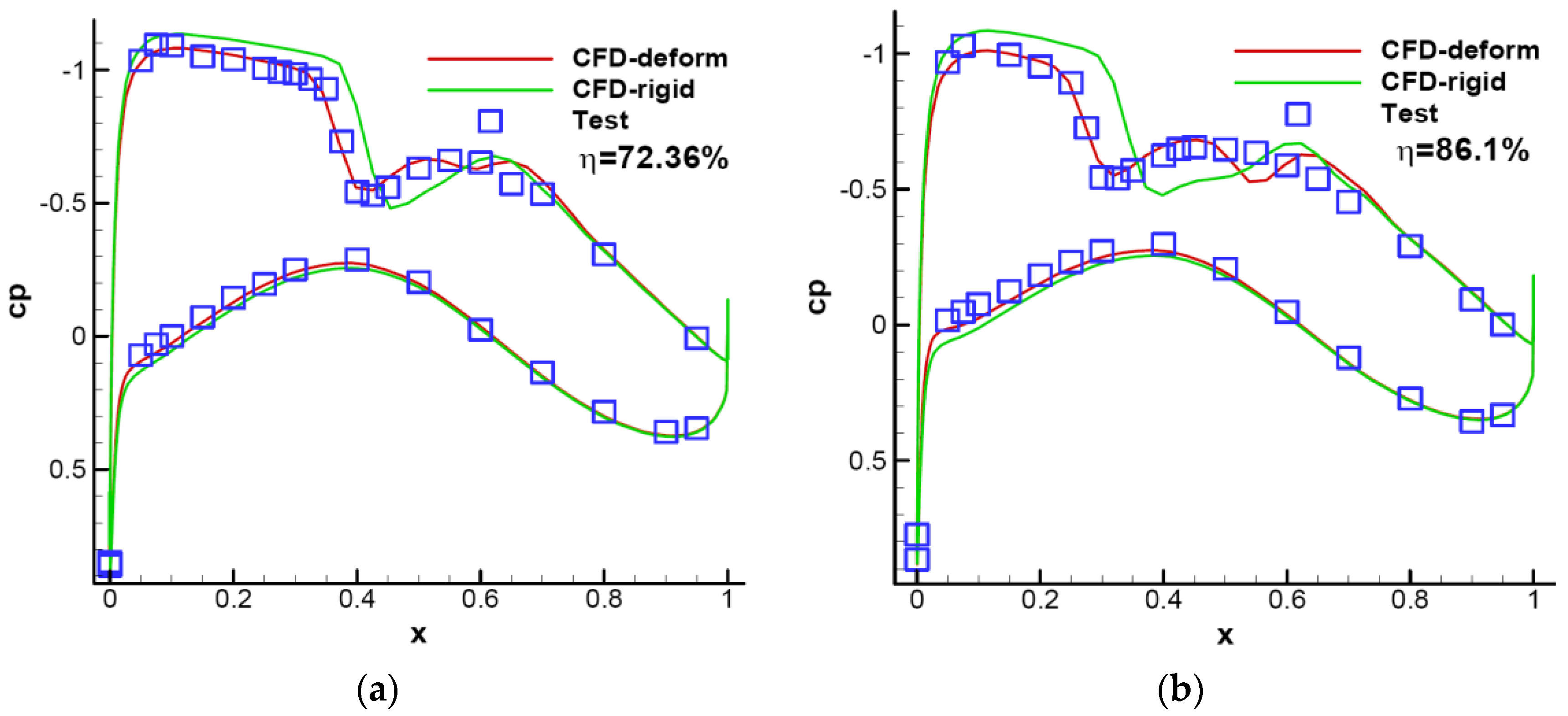
4.1. Wing Deformation Effect

Figure 4 illustrates the lift coefficient and pitching moment curves under different dynamic pressures. When the dynamic pressure increases from 40 to 92 kPa, the lift coefficient curve slope decreases, and the pitch moment coefficient curve slope also decreases. At higher dynamic pressure, effective angles of attack at the local section are reduced by twist deformation along the wing. This causes its aerodynamic center to move toward the leading edge along the chord, which leads to the pitch moment coefficient curve slope decrease as the lift coefficient curve slope decreases. Specific increments of the lift and pitching moment coefficients caused by dynamic pressure variation at different angles of attack are given in Figure 5. At the same angle of attack, the lift and the pitching moment coefficients are reduced about 0.01 and 0.0022, respectively.
The influence of wing deformation on pressure distribution at different test conditions is shown in Figure 6 and Figure 7. It can be seen from Figure 6 that the wing deformation has little impact on the pressure distribution in the case of α = 0° and M = 0.76 because the aerodynamic load is relatively low and the flow over the wing keeps attached. With the increase of the angle of attack, shock wave appears on the upper wing surface and the pressure distribution and corresponding shock wave location changes to some extent due to the higher aerodynamic load and larger wing deformation (Figure 7). Specifically, the shock wave moves toward the leading edge along the local airfoil chord due to the negative wing twist (local airfoil leading edge nose down). Additionally, the variation of pressure distribution becomes more severe from the wing root to the wing tip because of the larger wing deformation at the wing tip.
The wing deformation effect on the flow structure of the model was calculated by in-house developed CFD software using an advanced RANS-based turbulence model. Figure 8 demonstrates the flow structures of the rigid model and deformed model. As shown in Figure 8, compared to the rigid model, the separation region on the upper surface of the deformed wing tip is smaller because the local angle of attack decreases due to the negative wing twist.
It could be found from the above analysis that the wing deformation effect has to be corrected to obtain pure Reynolds number effects. In this study, the model deformation measured by the SPT technique and CFD are used in combination to correct the aeroelastic effect. Displacements along the wing measured by the SPT system reconstruct the deformed model configuration.
Figure 9 shows the comparison of surface pressure distribution data from CFD with an advanced RANS-based turbulence model and data from ETW wind tunnel tests. As illustrated in Figure 9, the shock wave position and the pressure distribution calculated by CFD are consistent with those from wind tunnel test, proving that the CFD methods used for aeroelastic effect correction in this study are reliable. It is worth mentioning that aerodynamic data used for evaluating Reynolds number effects in this paper are based on the rigid model without wing deformation.

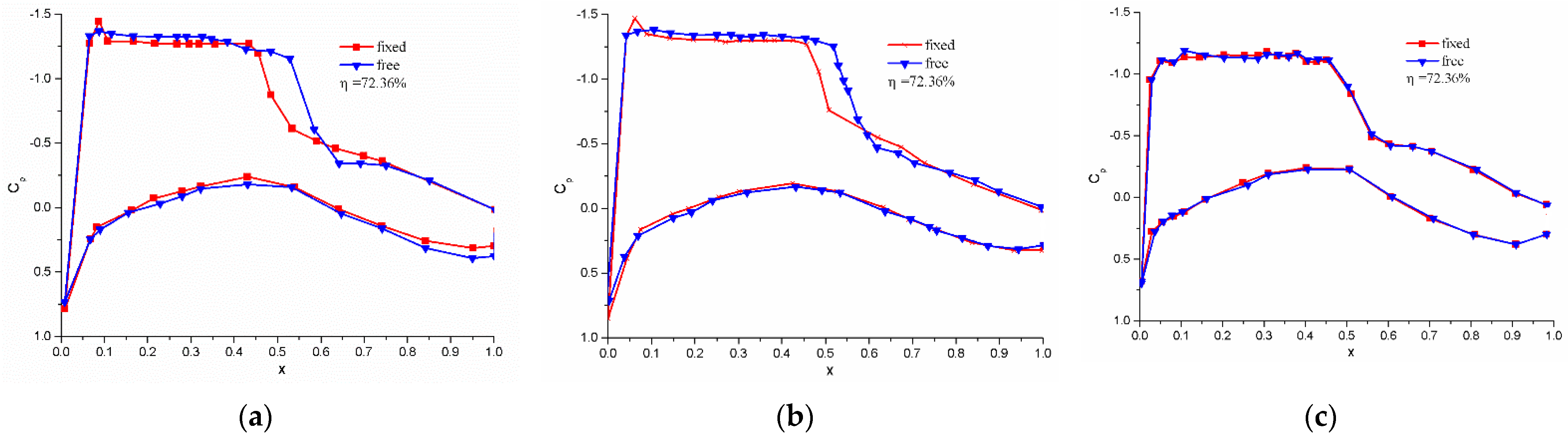
4.2. Influence of Transition Strips on Reynolds Number Effects

The flow structure and aerodynamic characteristics of supercritical wings are very sensitive to the boundary condition development. Due to the high Reynolds number during the real flight, the boundary layer on the wing transits near the leading edge and the flow over the wing is nearly fully turbulent. However, in wind tunnel tests, a wider laminar flow region is commonly achieved because of the much lower Reynolds number. Generally, the fixed transition by transition strips is adopted to simulate the flight boundary layer transition. However, the transition band should be removed when the test Reynolds number is approaching the flight Reynolds number. To establish a feasible Reynolds number effect correction method, it is significant to investigate Reynolds number dependencies with and without the transition band.
Figure 10 illustrates the pressure distributions with and without transition band under different Reynolds numbers. As shown in Figure 10, the transition fixing mainly affects the pressure distribution of the upper wing surface. The shock wave position with the transition band moves towards the leading edge up to 20% of the local chord and its strength is reduced to some extent at a low Reynolds number test condition (Re = 3.3 × 10⁶). The envelope area of the pressure distribution curve with fixed transition is smaller than that of free boundary layer transition. When transition grit strips are attached, the boundary layer becomes thicker, which is similar to the boundary development state at a lower Reynolds number. The thicker boundary layer can induce boundary layer separation early and the shock wave moves to a new position ahead of the flow separation accordingly. As the test Reynolds number increases, the boundary transition will occur ahead of the grit strips and the thickness of the boundary layer will mainly be impacted by Reynolds numbers, which makes the difference of the pressure distribution between the fixed transition mode and free transition mode smaller. However, the difference can be neglected when the Reynolds number is above 15 × 106. Based on the above analysis, it can be concluded that the transition strip can simulate the flight transition location but cannot simulate the boundary layer thickness and development on the supercritical wing surface. The shock wave location and pressure distribution with transition fixing at a low Reynolds number are significantly different to those in flight conditions. The transition band is mainly used in low Reynolds number wind tunnel tests to make the experimental data steadier. However, it can be removed when the test Reynolds number is high enough. For the supercritical wing employed in this research, the transition band is removed when the Reynolds number is higher than 15 × 106.

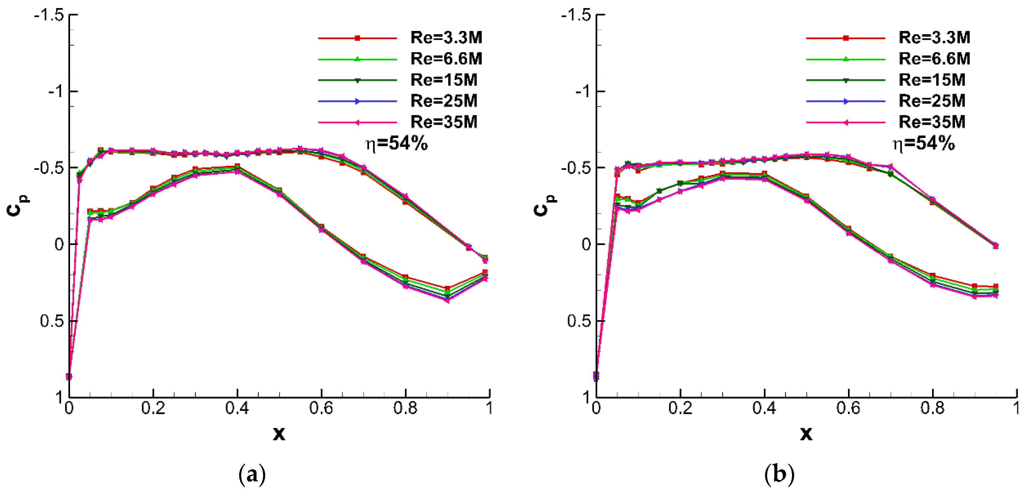
4.3. Reynolds Number Effect on the Pressure Distribution of Supercritical Wing

Figure 11 illustrates the pressure distributions under different Reynolds numbers at M = 0.76 and α = 0°. It can be seen that there is no shock wave in this condition and the pressure coefficient curve area that links to the lift coefficient becomes larger slightly as the test Reynolds number increases from 3.3 × 10⁶ to the flight Reynolds number 35 × 106. However, the variation of pressure coefficient distribution is not generally apparent.
As the angle of attack increases, the shock wave forms on the upper wing surface. Figure 12 shows the pressure distributions at different angles of attack and Reynolds numbers (M = 0.76). It can be found that the Reynolds number has a significant impact on the shock wave position. The pressure coefficient of the trailing edge becomes slightly more negative and the shock wave pushes downstream up to 10% of the local chord when the test Reynolds number increases from 3.3 × 10⁶ to the flight Reynolds number 35 × 106.
The flow structures in different Reynolds numbers and free stream conditions are simulated numerically based on the in-house developed CFD software to understand the Reynolds number effect on the aerodynamic properties of the supercritical wing in more detail. The numerical results show that the Reynolds number variation has little impact on the flow structures and the surface streamlines when shock wave and flow separation do not appear. When the Mach number and angle of attack are high enough to form a shock wave and/or the induced separation, the flow structures are quite sensitive to the Reynolds number. Figure 13 displays the numerical flow structures at Re = 3.3 × 10⁶ and 35 × 106 in the case of M = 0.76, α = 4°. As illustrated in Figure 13, the shock wave and separation bubble appear near the outer part of the upper supercritical wing surface. As the Reynolds number increases from 3.3 × 10⁶ to 35 × 106, the shock wave and the separation are pushed downward and the size of the separation bubble is reduced significantly, resulting in the stronger span flow behind the separation bubble. Figure 14 illustrates the numerical flow structures at Re = 3.3 × 10⁶ and 35 × 106 in the case of M = 0.76, α = 6°. As the angle of attack increases from 4° to 6° at M = 0.76, the flow separation becomes much more severe and crossflow appears in the most domain of the upper wing. When the Reynolds number increases to 35 × 106, the size of backflow behind the shock wave is significantly reduced and the crossflow near the wing root becomes much weaker.

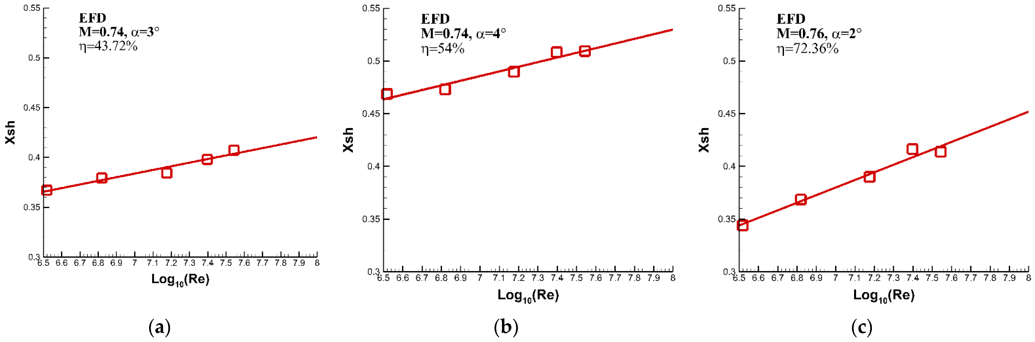
4.4. Reynolds Number Effect on Shock Wave Position

The shock wave position (designated by non-dimensional parameter, Xsh) affects the separation type and size of the boundary layer, the surface pressure distribution, and the overall aerodynamic forces of the supercritical wing. Figure 15 shows the variation of shock wave position with the logarithm of the Reynolds number obtained from ETW wind tunnel tests. It is worth mentioning that the discrete surface pressure data from wind tunnel tests are fitted and the shock wave positions are determined based on the method proposed by J. F. Cahill and P. C. Connor [5]. As can be seen from Figure 15, the shock wave moves towards the trailing edge along the local airfoil chord when the Reynolds number increases, and the shock wave position varies linearly with the logarithm of the Reynolds number. In the case of M = 0.76, α = 2°, the shock wave position moves towards the trailing edge along the local airfoil chord up to 7% of the local chord as the Reynolds number increases from 3.3 × 10⁶ to 35 × 106 at a location of 72.36% of the wingspan. It seems that shock wave positions at the flight Reynolds number might be extrapolated from experiment results obtained in conventional wind tunnels with a relatively low Reynolds number range.

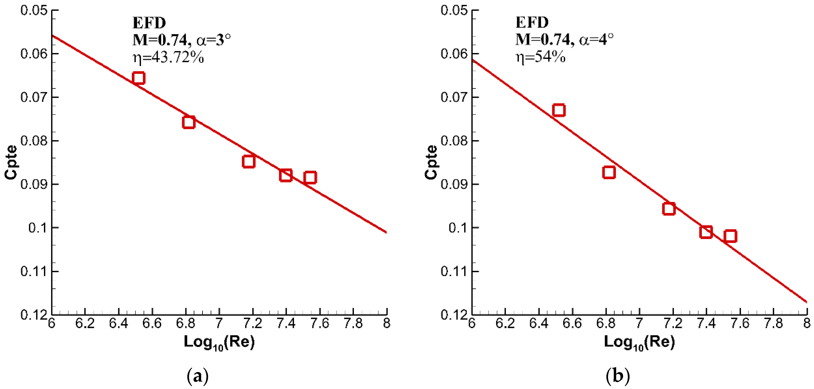
4.5. Reynolds Number Effect on Trailing Edge Pressure Recovery

The trailing edge pressure recovery can be used to analyze the flow recovery characteristics behind the shock wave or the induced separation, which is related to the shock wave position and strength. Typical results of the trailing edge pressure coefficient measured from ETW wind tunnel tests are shown in Figure 16. As can be seen from Figure 16, the trailing edge pressure coefficients show an increase trend as the test Reynolds number increases. In the case of M = 0.76, α = 2°, the trailing edge pressure increases 0.02 as the Reynolds number increases from 3.3 × 10⁶ to 35 × 106 at a location of 43.72% of the wingspan. Additionally, an approximate linear growth of the trailing edge pressure with the logarithm of the Reynolds number can be found, which is consistent with the trend of shock wave position variation.

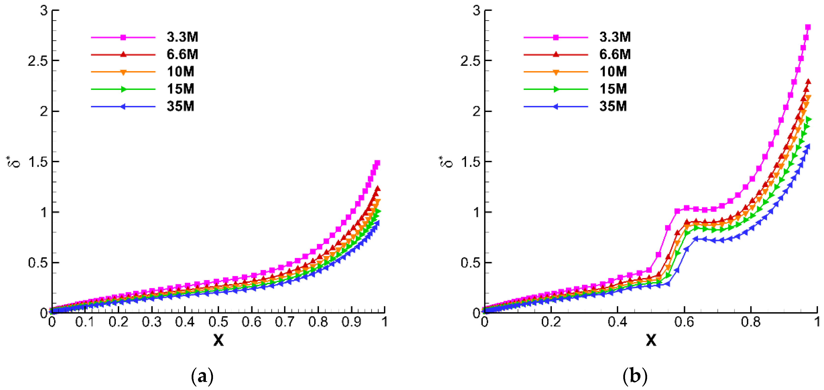
4.6. Reynolds Number Effect on Boundary Layer Thickness

The Reynolds number that relates to the ratio of inertia force to viscous force is one of the most crucial similarity parameters in flight vehicle aerodynamics. Its direct impact on flow characteristics is the development of the boundary layer, which affects the shock wave position and strength. To understand the mechanism of the Reynolds number effects on aerodynamic characteristics of the supercritical wing, the boundary layer displacement thicknesses under different Reynolds numbers are numerically simulated based on in-house developed CFD software. The displacement thickness of the boundary layer is calculated by
δ * = 0 δ ( 1 v x U ) d y
where δ * is boundary thickness, U is the flow velocity.
Figure 17 illustrates the numerical boundary layer displacement thicknesses of the upper wing surface at different Reynolds numbers in the case of M = 0.76, η = 0.35. As seen in Figure 17, there is no shock wave on the upper wing surface in the case of M = 0.76, α = 0° and the boundary layer displacement thickness becomes significantly thinner as the Reynolds number increases from 3.3 × 10⁶ to 35 × 106. To be specific, the boundary layer displacement thickness is reduced by 0.07 mm at the location of 20% of the local chord and 0.25 mm at the location of 80% of the local chord when the Reynolds number is increased from 3.3 × 10⁶ to 35 × 106. By contrast, the shock wave appears on the upper surface in the case of M = 0.76, α = 4°. In this condition, the displacement thickness of the boundary layer increases rapidly around the shock wave foot, but it still decreases with the growth in Reynolds number. In addition, the starting location of the boundary layer displacement thickness has a dramatic increase that corresponds to the shock wave position moving toward the trailing edge along the local chord as the Reynolds number increases, which is consistent with the trend obtained from the experimental surface pressure distribution discussed in Section 4.4.

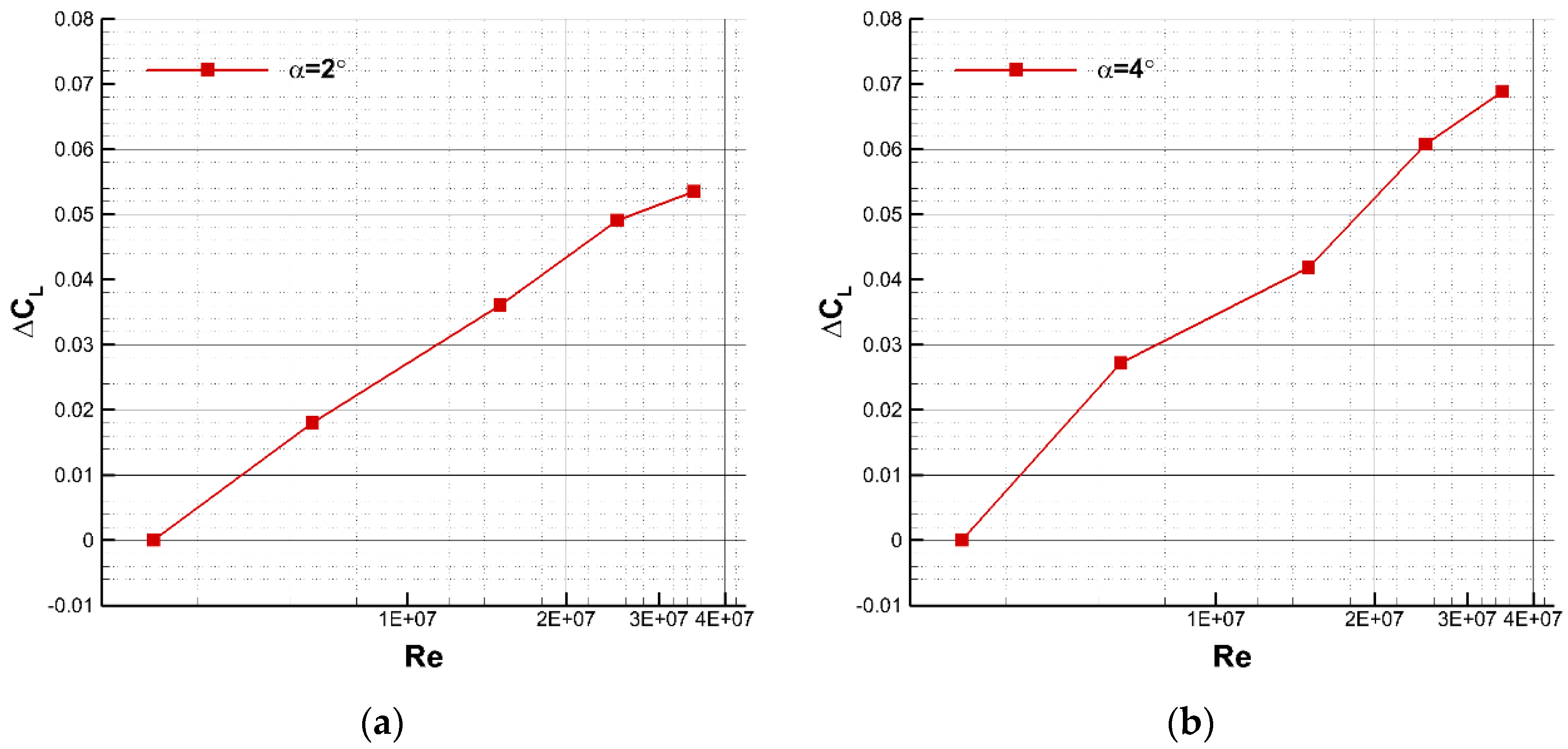
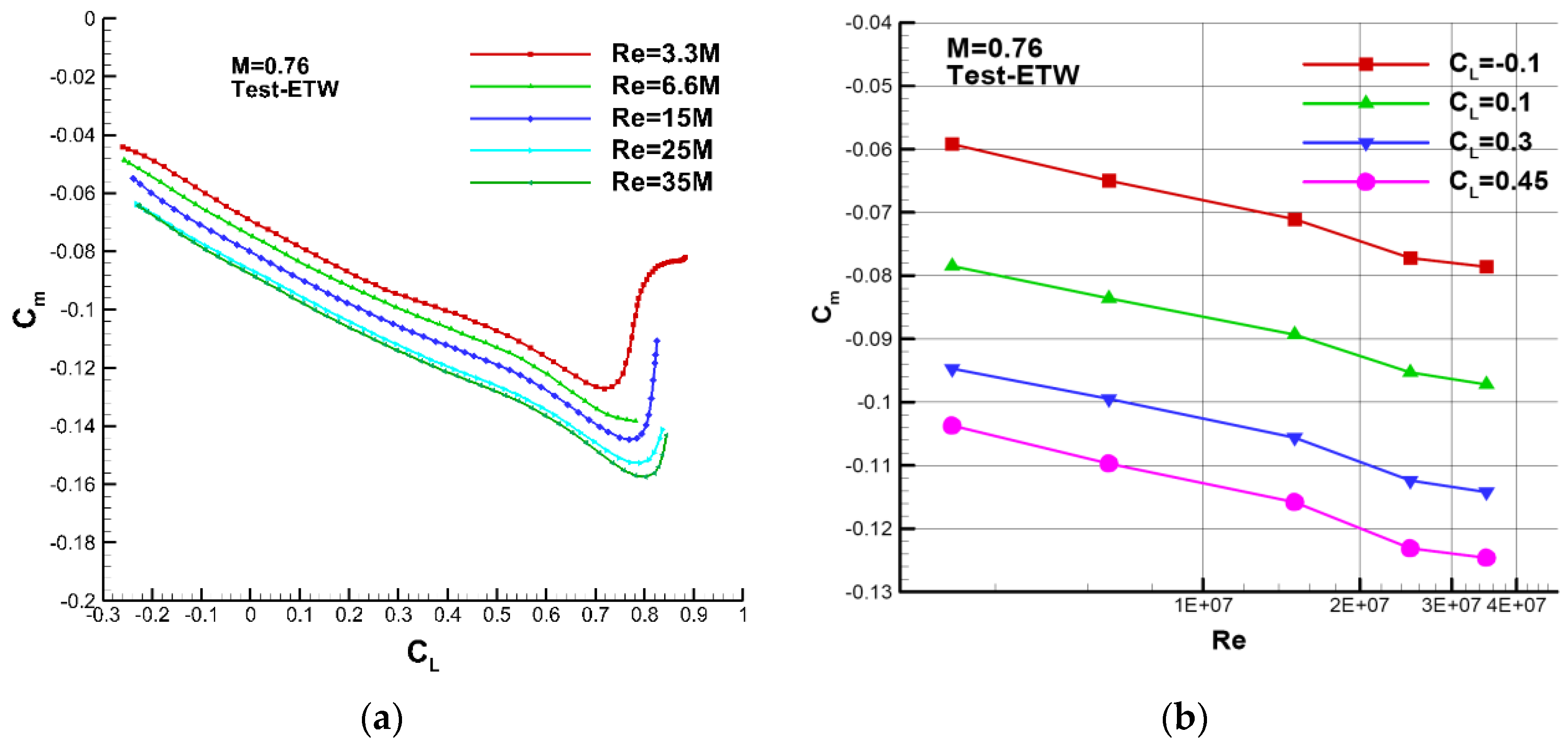
4.7. Pure Reynolds Number Effect on Aerodynamic Characteristics of the Transport Aircraft

Figure 18 illustrates typical lift coefficient curves of the test model obtained by surface pressure integration at different Reynolds numbers. As shown in Figure 18, the lift coefficient increases and the zero-lift angle is reduced at a higher Reynolds number. Moreover, the lift coefficient slope becomes larger as the test Reynolds number increases but the impact of Reynolds number on the lift coefficient becomes smaller when the Reynolds number exceeds 25 × 106. The curves of lift coefficient increment (ΔCL) curves versus the logarithm of the Reynolds number are given in Figure 19. It can be seen that the curve of the lift coefficient increment versus the logarithm of the Reynolds number is approximately linear, but the change in ΔCL starts to be less steep when the test Reynolds number is higher than 25 × 106. The effect of the Reynolds number on the pitch moment coefficient (Cm) and the polar curve (Cm-CL) is shown in Figure 20. As the Reynolds number increases, extra nose-down pitch moment is produced and the critical angle of attack for the pitching instability is postponed, resulting in an extended linear segment of the pitch moment curve. On the other hand, the wind tunnel results show that the aerodynamic center keeps approximately unchanged when the Reynolds number varies from 3.3 × 10⁶ to 35 × 106 and the Mach number is less than 0.79. However, while the aerodynamic center moves toward the trailing edge of the local airfoil to some extent when the Mach number is larger than 0.79. For example, the aerodynamic center position change is about 3.88% of the mean aerodynamic chord in the case of M = 0.82.

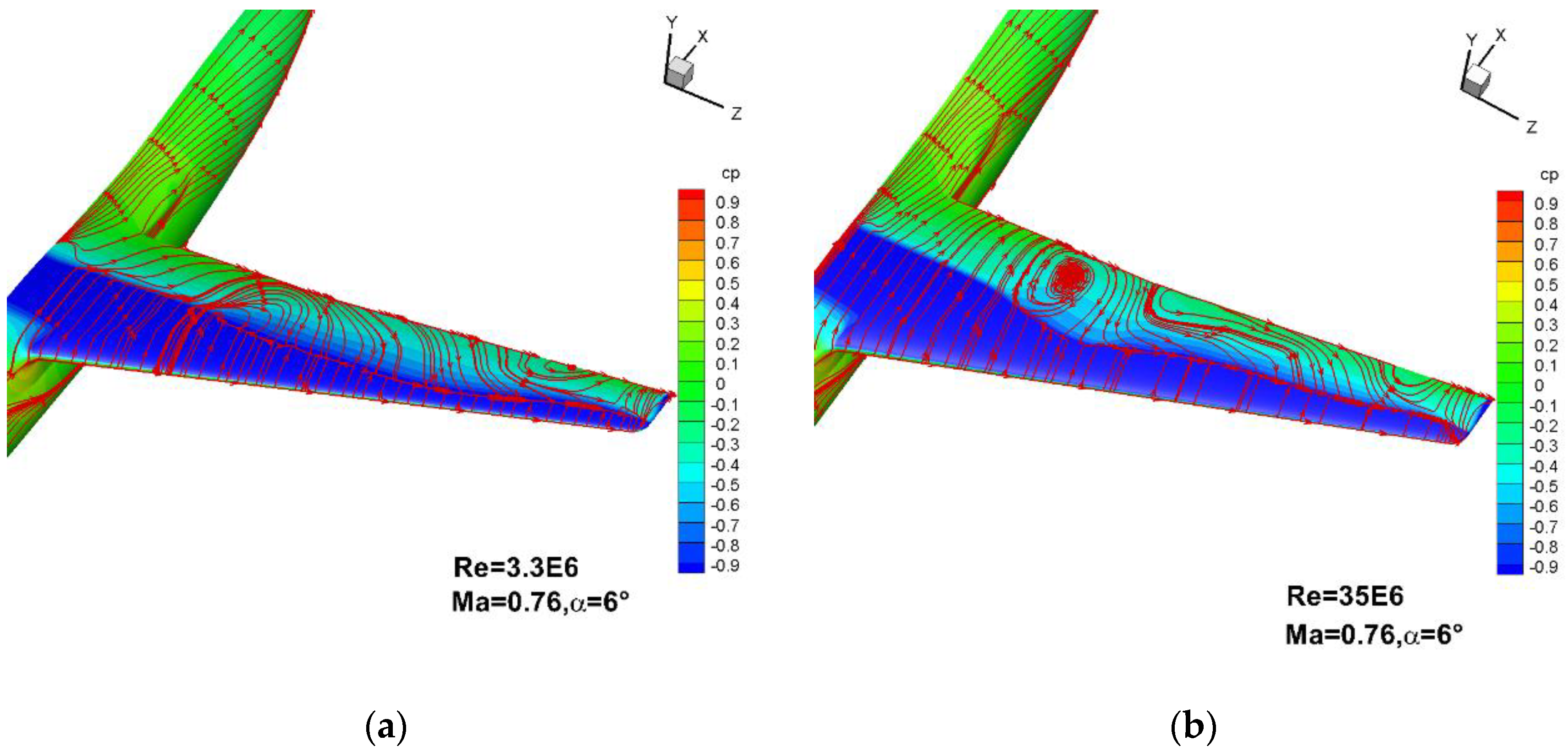
4.8. Analysis of the Mechanism of Reynolds Number Effect on Flow over the Supercritical Wing

The boundary layer thickness of the supercritical wing is thicker at low Reynolds numbers. The relatively thick boundary layer develops along the chord and the corresponding trailing edge boundary thickness increases, resulting in a reduced effective trailing edge camber. By contrast, the effective camber near the trailing edge increases with the Reynolds number, which can improve the lift force and decrease the zero-lift angle. This effect becomes more apparent at higher Mach numbers, in particular when shock wave appears. When the Mach number is low and there is no shock wave on the upper wing surface, the lift increase in the case of a higher Reynolds number is mainly induced by the aforementioned effective camber increase. However, when the Mach number is high enough and the shock wave forms, the lift coefficient increases because of the shock wave downward movement in combination with the effect of the effective trailing edge camber increase. It can be concluded that Reynolds number has a significant impact on aerodynamic characteristics of the supercritical wing when shock wave appears and the essence of the Reynolds number effect is the variation of shock wave/boundary layer interaction and the induced boundary layer separation at different Reynolds numbers. The shock wave can interact with two types of boundary layers: the laminar boundary layer and turbulent boundary layer. In the case of the laminar boundary layer with a poor ability to resist the negative pressure gradient, the flow is more likely to separate. For the turbulent boundary layer, there are three types of boundary layer separations: the initial flow separation just behind the shock wave, the shock wave induced separation bubble and the full flow separation behind the shock wave. At a small angle of attack, the shock wave moves toward the trailing edge along the local chord and the tendency of flow separation is weakened with a higher Reynolds number. Figure 21 demonstrates the numerical flow structures of the supercritical wing at different Reynolds numbers in the case of M = 0.76, α = 6°. As shown in Figure 21, the full flow behind the shock wave separates and a strong vortex forms around the trailing edge in the case of Re = 3.3 × 10⁶. When the Reynolds number increases to 35 × 106, the flow separation is significantly weakened, the strong vortex is replaced by a separation bubble and the full separation flow behind the shock wave is replaced by the reattached flow behind the separation bubble.
In the presence of a shock wave, the flow ahead of the shock wave is supersonic, and the flow velocity reduces from supersonic to zero within the boundary layer. On the other hand, the shock wave is terminated by a sonic line in the boundary layer. The pressure dramatically increases behind the shock wave and the higher pressure is transmitted downward through the subsonic layer underneath the sonic line, resulting in a strong pressure gradient. The kinetic energy of the boundary layer is constantly lost because of the flow viscosity. When its kinetic energy is not strong enough to resist the negative pressure gradient, the backward flow and flow separation appear, which can induce more severe energy loss. At high test Reynolds numbers, the relative flow viscosity decreases with a thinner boundary layer and the effective camber of the supercritical airfoil increases, which makes the shock wave move toward the trailing edge along the local chord. From the perspective of the boundary layer, the energy loss caused by flow viscosity is reduced, and the boundary layer can remain attached in a longer distance under the same negative pressure gradient, which weakens the separation to some extent.

5. Conclusions

Due to the complex flow phenomena during the cruise of transport aircraft including shock wave, shock/boundary layer interaction, flow viscosity effect, boundary layer development and separation, the variation in the Reynolds number can result in an apparent change of the flow structure and overall aerodynamic forces. Reynolds number effects on aerodynamic characteristics of a transport aircraft are investigated in detail based on cryogenic wind tunnel tests and CFD tools. The ETW wind tunnel results show that the aeroelastic deformation of the supercritical wing in wind tunnel tests has a considerable impact on aerodynamic characteristics in the presence of shock wave, which might even exceed the effect of the Reynolds number. Furthermore, the transition band can improve the stability and repeatability of the wind tunnel data and simulate the in-flight transition location to some extent; however, it cannot simulate the boundary layer thickness and development on the supercritical wing surface. In this study, the wing deformation effect is corrected through in-house developed CFD software that has been validated by the wind tunnel data and the transition band is removed when the test Reynolds number is higher than 15 × 106. Combining the ETW wind tunnel test data and numerical results from CFD, it can be concluded that the Reynolds number has a weak impact on the aerodynamic characteristics of the supercritical wing when the shock wave does not appear, but dramatic Reynolds number effects can be found in the presence of the shock wave. Reynolds number effect on aerodynamic characteristics over the supercritical wing are essentially a kind of mutual interference among boundary layer, shock wave, and induced flow separation. The lift coefficient and the slope of lift curve become larger as the test Reynolds number increases; however, the impact of Reynolds number on the lift coefficient becomes smaller when the Reynolds number exceeds 25 × 106. Moreover, as the Reynolds number increases, extra nose-down pitch moment is produced when the Reynolds number varies from 3.3 × 10⁶ to 35 × 106 and the Mach number is less than 0.79. The results obtained in this study can be used to develop Reynolds number effect correction and extrapolation methods for conventional wind tunnel test data.

Author Contributions

Conceptualization, Y.W. and G.L.; methodology, Y.W. and G.L.; Formal analysis, G.L. and D.L.; Investigation, X.X. and D.L.; Software, X.X.; Supervision, D.L.; Writing—original draft, Y.W.; Writing—review and editing, G.L. All authors have read and agreed to the published version of the manuscript.

Funding

This research was funded by the state key lab of aerodynamics of China Aerodynamics Research and Development Center, grant number SKLA2019030101.

Institutional Review Board Statement

Not applicable.

Informed Consent Statement

Not applicable.

Data Availability Statement

Not applicable.

Conflicts of Interest

The authors declare no conflict of interest.

Nomenclature

Caaxial force coefficient
CLlift force coefficient
Cmpitching moment coefficient taking the center point of the fuselage at the location of ¼ of the mean aerodynamic chord as the reference point
Cnnormal force coefficient
Cpisurface pressure coefficient of the orifice tap i
Cptetailing edge pressure coefficient
MMach number
pisurface pressure of the orifice tap i
p∞:static pressure of the free stream
Q, qdynamic pressure of the free stream
ReReynolds number
Uflow velocity
Xshshock wave location (non-dimensional) along the span
αangles of attack
ηrelative location of local airfoil along the span
δboundary thickness

References

  1. Zhang, Y.; Chen, H.; Zhang, M.; Zhang, M.; Liu, T.; Zhang, W.; Fu, S. Supercritical wing design and optimization for transonic civil airplane. In Proceedings of the 49th AIAA Aerospace Sciences Meeting Including the New Horizons Forum and Aerospace Exposition, Orlando, FL, USA, 4–7 January 2011; American Institute of Aeronautics and Astronautics: Reston, VA, USA, 2011. [Google Scholar]
  2. Garabedian, P.; McFadden, G. Design of supercritical swept wings. AIAA J. 1982, 20, 289–291. [Google Scholar] [CrossRef]
  3. Zhao, T.; Zhang, Y.; Chen, H.; Chen, Y.; Zhang, M. Supercritical wing design based on airfoil optimization and 2.75d transformation. Aerosp. Sci. Technol. 2016, 56, 168–182. [Google Scholar] [CrossRef]
  4. Sobieczky, H.; Seebass, A.R. Supercritical airfoil and wing design. Annu. Rev. Fluid Mech. 1984, 16, 337–363. [Google Scholar] [CrossRef]
  5. Quest, J. Etw: Simulations of true flight behaviour. Air Space Eur. 2001, 3, 115–118. [Google Scholar] [CrossRef]
  6. Quest, J.; Wright, M. Investigation of a modern transonic transport aircraft configuration over a large range of reynolds numbers. In Proceedings of the 40th Aiaa Aerospace Sciences Meeting & Exhibit, Reno, NV, USA, 14–17 January 2002; American Institute of Aeronautics and Astronautics: Reston, VA, USA, 2002. [Google Scholar]
  7. MacWilkinson, D.G.; Blackerby, W.T.; Paterson, J.H. Correlation of Full Scale Drag Predictions with Flight Measurements on the C1414 Aircraft. Phase II: Wind Test, Analysis and Prediction Techniques; NASA: Washington, DC, USA, 1974. [Google Scholar]
  8. Pettersson, K.; Rizzi, A. Aerodynamic scaling to free flight conditions: Past and present. Prog. Aerosp. Sci. 2008, 44, 295–313. [Google Scholar] [CrossRef]
  9. Wahls, R. The national transonic facility—A research retrospective. In Proceedings of the 39th Aerospace Sciences Meeting and Exhibit, Reno, NV, USA, 8–11 January 2001; American Institute of Aeronautics and Astronautics: Reston, VA, USA, 2001. [Google Scholar]
  10. Hefer, G. Etw—A facility for high reynolds number testing. In IUTAM Symposium Transsonicum IV; Springer: Dordrecht, The Netherlands, 2003. [Google Scholar]
  11. Green, J.; Quest, J. A short history of the European transonic wind tunnel etw. Prog. Aerosp. Sci. 2011, 47, 319–368. [Google Scholar] [CrossRef]
  12. Elsenaar, A. Observed Reynolds Number Effects on Airfoils and High Aspect Ratio Wings at Transonic Flow Conditions. GARDograph 1988, 303, 17–49. [Google Scholar]
  13. Curtin, M.; Bogue, D.; Om, D.; Rivers, S.; Pendergraf, O.; Wahls, R. Investigation of transonic Reynolds number scaling on a twin-engine transport. In Proceedings of the 40th AIAA Aerospace Sciences Meeting and Exhibit, Reno, NV, USA, 14–17 January 2002. [Google Scholar]
  14. Clark, R.; Pelkman, R. High Reynolds number testing of advanced transport aircraft wings in the national transonic facility (invited). In Proceedings of the 39th AIAA Aerospace Sciences Meeting & Exhibit, Reno, NV, USA, 8–11 January 2001. [Google Scholar]
  15. Rudnik, R.; Germain, E. Germain Reynolds number scaling effects on the European high-lift configurations. J. Aircr. 2009, 46, 1140–1151. [Google Scholar] [CrossRef]
  16. Om, D.; Curtin, M.; Bogue, D.; Witkowski, D.; Ball, D. Reynolds number effects on a subsonic transport at transonic conditions. In Proceedings of the 39th Aerospace Sciences Meeting and Exhibit, Reno, NV, USA, 8–11 January 2001. [Google Scholar]
  17. Wahls, R.; Owens, L.; Rivers, S. Rivers Reynolds number effects on a supersonic transport at transonic conditions. In Proceedings of the 39th Aerospace Sciences Meeting and Exhibit, Reno, NV, USA, 8–11 January 2001. [Google Scholar]
  18. Melber-Wilkending, S.; Wichmann, G. Wichmann application of advanced CFD tools for high reynolds number testing. In Proceedings of the 47th AIAA Aerospace Sciences Meeting Including the New Horizons Forum and Aerospace Exposition, Orlando, FL, USA, 5–8 January 2009. [Google Scholar]
  19. Fukushima, Y.; Tamaki, Y.; Kawai, S. Predictability of wall-modeled les for Reynolds number effects of airfoil flows at transonic buffet and near-stall conditions. In Proceedings of the AIAA SciTech Forum, Orlando, FL, USA, 6–10 January 2020. [Google Scholar]
  20. Masini, L.; Timme, S.; Peace, A.J. Reynolds number effects on wing shock buffet unsteadiness. In Proceedings of the AIAA AVIATION Forum, Dallas, TX, USA, 17–21 June 2019. [Google Scholar]
  21. Wick, A.T.; Hooker, J.R.; Walker, J.; Chan, D.T.; Plumley, R.; Zeune, C. Hybrid wing body performance validation at the national transonic facility. In Proceedings of the 55th AIAA Aerospace Sciences Meeting, Grapevine, TX, USA, 9–13 January 2017. [Google Scholar]
  22. Liu, D.; Xu, X.; Li, Q.; Jiang, M.; Peng, X. Numerical investigation on the Reynolds number effects of supercritical wing. In Proceedings of the 5th International Conference on Intelligent Systems Design and Engineering Applications, Hunan, China, 15–16 June 2014. [Google Scholar]
  23. Liu, D.; Chen, D.; Li, Q.; Xu, X.; Peng, X. Investigation on the correlation of CFD and EFD results for a supercritical wing. Int. J. Heat Technol. 2015, 33, 19–26. [Google Scholar] [CrossRef]
  24. Xu, X.; Liu, D.W.; Chen, D.H.; Wang, Y.J. Reynolds number effect investigation of shock wave on supercritical airfoil. Appl. Mech. Mater. 2014, 548, 520–524. [Google Scholar] [CrossRef]
  25. Liu, D.; Wang, Y.; Chen, D.; Peng, X.; Xu, X. Numerical investigation on the Reynolds number effects of supercritical airfoil. Procedia Eng. 2012, 31, 103–109. [Google Scholar] [CrossRef] [Green Version]
  26. Pettersson, K.; Rizzi, A. Estimating Reynolds number scaling and windtunnel boom effects with the help of CFD methods. In Proceedings of the 24th Applied Aerodynamics Conference, San Francisco, CA, USA, 5–8 June 2006. [Google Scholar]
  27. Brodersen, M.R.; Amant, S.; Larrieu, P.; Destarac, D.; Sutcliffe, M. Airbus, ONERA, and DLR results from the 2nd AIAA drag prediction workshop. In Proceedings of the 42nd AIAA Aerospace Sciences Meeting and Exhibit, Reno, NV, USA, 5–8 January 2004. [Google Scholar]
  28. Vassberg, J.; Tinoco, E.; Mani, M.; Brodersen, O.; Eisfeld, B.; Wahls, R.; Morrison, J.; Zickuhr, T.; Laflin, K.; Mavriplis, D. Summary of the third AIAA CFD drag prediction workshop. In Proceedings of the 45th AIAA Aerospace Sciences Meeting and Exhibit, Reno, NV, USA, 8–11 January 2007. [Google Scholar]
  29. Quix, H.; Semmelmann, J.; Wright, M. Model deformation measurement capabilities at ETW. In Proceedings of the 31st AIAA Aerodynamic Measurement Technology and Ground Testing Conference, Dallas, TX, USA, 22–26 June 2015; American Institute of Aeronautics and Astronautics: Reston, VA, USA, 2015. [Google Scholar]
  30. Germain, E.; Quest, J. The development and application of optical measurement techniques for high reynolds number testing in cryogenic environment. In Proceedings of the 43rd Aiaa Aerospace Sciences Meeting and Exhibit, Reno, NV, USA, 10–13 January 2005; American Institute of Aeronautics and Astronautics: Reston, VA, USA, 2005. [Google Scholar]
  31. Noviello, M.C.; Dimino, I.; Concilio, A.; Amoroso, F.; Pecora, R. Aeroelastic assessments and functional hazard analysis of a regional aircraft equipped with morphing winglets. Aerospace 2019, 6, 104. [Google Scholar] [CrossRef] [Green Version]
Figure 1. Aerodynamic circuit sketch of the ETW facility.
Aerospace 08 00177 g001
Figure 2. Model configuration and distribution of orifice taps.
Aerospace 08 00177 g002
Figure 3. SPT markers on the supercritical wing.
Aerospace 08 00177 g003
Figure 4. Longitudinal aerodynamic characteristics under different dynamic pressures (M = 0.76, Re = 15 × 106): (a) lift coefficient; (b) pitching moment coefficient.
Aerospace 08 00177 g004
Figure 5. Increments of the lift and pitching moment coefficients caused by dynamic pressure variation (M = 0.76, Re = 15 × 106): (a) increments of the lift coefficient; (b) increments of the pitching moment coefficient.
Aerospace 08 00177 g005
Figure 6. Pressure distributions under different dynamic pressures (α = 0°, M = 0.76, Re = 15 × 106): (a) η = 54%; (b) η = 96.61%.
Aerospace 08 00177 g006
Figure 7. Pressure distributions under different dynamic pressures (α = 2°, M = 0.76, Re = 15 × 106): (a) η = 54%; (b) η = 96.61%.
Aerospace 08 00177 g007
Figure 8. Numerical flow patterns near the wing tip with and without deformation (M = 0.76, Re = 15 × 106, Q = 94 kPa, α = 4°): (a) rigid model; (b) deformed model.
Aerospace 08 00177 g008
Figure 9. Comparison of surface pressure distributions from CFD and ETW wind tunnel tests (M = 0.76, Re = 15 × 106, α = 2°): (a) η = 72.3%; (b) η = 86.1%.
Aerospace 08 00177 g009
Figure 10. Pressure distributions with and without transition band under different Reynolds numbers (M = 0.76, α = 4°, η = 72.36%): (a) Re = 3.3 × 10⁶; (b) Re = 6.6 × 10⁶; (c) Re = 15 × 106.
Aerospace 08 00177 g010
Figure 11. Pressure distributions under different Reynolds numbers (M = 0.76, α = 0°): (a) η = 54%; (b) η = 72.36%.
Aerospace 08 00177 g011
Figure 12. Pressure distributions at different angles of attack and Reynolds numbers (M = 0.76, η = 54%): (a) α = 2°; (b) α = 4°.
Aerospace 08 00177 g012
Figure 13. Numerical flow structures at different Reynolds numbers (M = 0.76, α = 4°): (a) Re = 3.3 × 10⁶; (b) Re = 35 × 106.
Aerospace 08 00177 g013
Figure 14. Numerical flow structures at different Reynolds numbers (M = 0.76, α = 6°): (a) Re = 3.3 × 10⁶; (b) Re = 35 × 106.
Aerospace 08 00177 g014
Figure 15. Reynolds number effect on shock wave position: (a) M = 0.74, α = 3°, η = 43.72%; (b) M = 0.74, α = 4°, η = 54%; (c) M = 0.76, α = 3°, η = 72.36%.
Aerospace 08 00177 g015
Figure 16. Reynolds number effect on trailing edge pressure recovery (M = 0.74): (a) α = 3°, η = 43.72%; (b) α = 4°, η = 54%.
Aerospace 08 00177 g016
Figure 17. Numerical boundary layer displacement thicknesses of the upper wing surface at different Reynolds numbers (M = 0.76, η = 0.35): (a) α = 0°; (b) α = 4°.
Aerospace 08 00177 g017
Figure 18. Typical lift coefficient curves at different Reynolds numbers: (a) M = 0.76; (b) M = 0.79.
Aerospace 08 00177 g018
Figure 19. Increments of lift coefficient versus Reynolds number (M = 0.76): (a) α = 2°; (b) α = 4°.
Aerospace 08 00177 g019
Figure 20. Pitch moment coefficient and polar curves at different Reynolds number: (a) polar curves; (b) pitch moment coefficient.
Aerospace 08 00177 g020
Figure 21. Numerical flow structures at different Reynolds numbers (M = 0.76, η = 63%, α = 6°): (a) Re = 3.3 × 10⁶; (b) Re = 35 × 106.
Aerospace 08 00177 g021
Table 1. Parameters of the 4 sets of grids.
Grid QualityFlow DirectionWingspan DirectionNormal DirectionLeading EdgeGrid Quantity (Million, M)
Coarsest141736992
Coarser1919973134
Medium2971291051710
Densest3591751132120
Publisher’s Note: MDPI stays neutral with regard to jurisdictional claims in published maps and institutional affiliations.

