1. Introduction
State-of-the-art interior noise models, both experimental and numerical, often have a mass gap. This gap arises since the consideration of secondary structural components, which are generally small in mass but large in numbers, is challenging, not to say tedious, and therefore often neglected. Nevertheless, it is well known that, in the case of an aircraft structure, the secondary masses comprise a significant part of the overall mass of the structure, wherefore the ambition to develop detailed acoustical models which efficiently include non-structural masses is an ongoing process [
1,
2,
3].
In the numerical domain, simple approaches where the secondary masses are condensed to point masses and subsequently connected to the primary structure have already been implemented and evaluated, see Seidel et al. [
4,
5]. To meet a more realistic representation of the acoustic model, the scope of this paper is to take into account linking elements and their inherited parametric uncertainties, which are assumed to be damping and stiffness coefficients as well as the overall mass of the connected structural components. Additionally, means to assess parametric sensitivities for a consequent identification of worst-case scenarios regarding structural response and alteration options for structural components shall be provided.
In the context of the German aviation research program LuFoV-2 Acoustic FlightLAB, an acoustic demonstrator has been developed, both physically at the Center of Applied Aeronautical Research in Hamburg and numerically, and validated up to a frequency of 500 Hz by Wandel et al. [
6]. The present work will take this demonstrator’s geometric and material properties into account for better scientific exchange and interdisciplinary compatibility. Finally, the authors would like to refer to the final report of the aviation research program mentioned, see [
7], for a further in-depth discussion of applied methods and results.
2. Materials and Methods
In contrast to the well known and easy to implement Monte Carlo sampling method, which randomly generates deterministic values for parameters with known probability density functions and therefore needs a lot of samples to cover the full range of uncertainty, the so-called fuzzy arithmetic provides a procedure to create structured parameter combinations, which subsequently will be used to evaluate the results of a model subjected to uncertainty.
The concept of fuzzy sets originally was developed by Zadeh [
8] as an extension of the many-valued logic, leading to fuzzy logic [
9] applied to linguistic variables, and subsequently resulting in a growing interest in engineering sciences for describing parameter uncertainties in numerical calculations, e.g., control, data analyses, and management as discussed in [
10]. However, standard fuzzy arithmetic has some limitations. In [
11], Hanss shows the phenomenon of overestimation of results in engineering mechanics, depending on the actual form of the fuzzy rational expression. As a solution to overcome these drawbacks, he introduced the advanced fuzzy arithmetic.
In the following subsections, a definition of fuzzy numbers and, based on Hanss’ advanced fuzzy arithmetic, the general procedure to simulate a system with uncertain input parameters will be given.
2.1. Fuzzy Sets and Fuzzy Numbers
Unlike classical crisp sets, a fuzzy set does not distinguish between members and non-members. The membership to a certain set
is described by a membership function
which takes any value between 0 and 1
A fuzzy number
is a fuzzy set
characterized by the following four conditions [
11]:
is normal ().
is convex.
There is exactly one with , which is called the modal value.
The membership function , , is at least piecewise continuous.
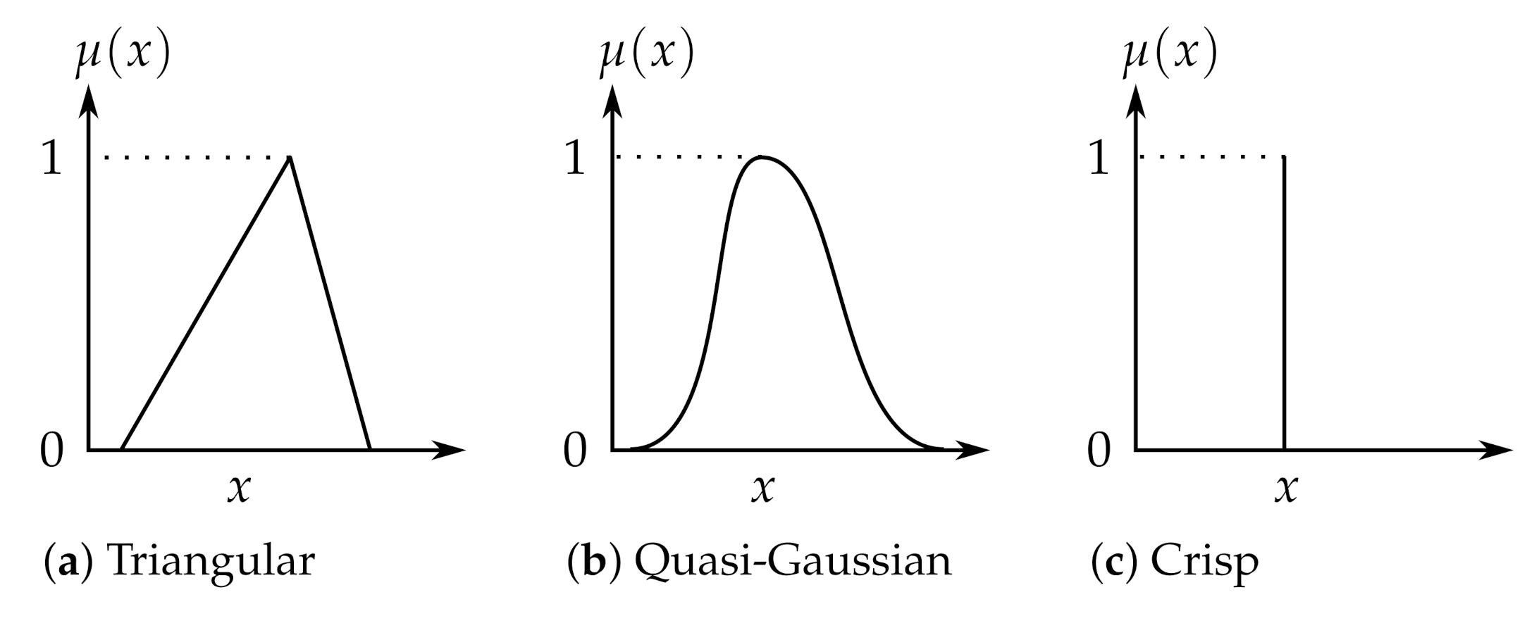
Obeying these rules, easily fuzzy number representations of parameter uncertainties can be developed. Examples of plausible fuzzy shapes are shown in
Figure 1.
2.2. The General Transformation Method
A simulation of a fuzzy-parameterized system with n uncertain parameters and a fuzzy output can be conducted by the following steps:
- I
Decomposition of Fuzzy Input Parameters
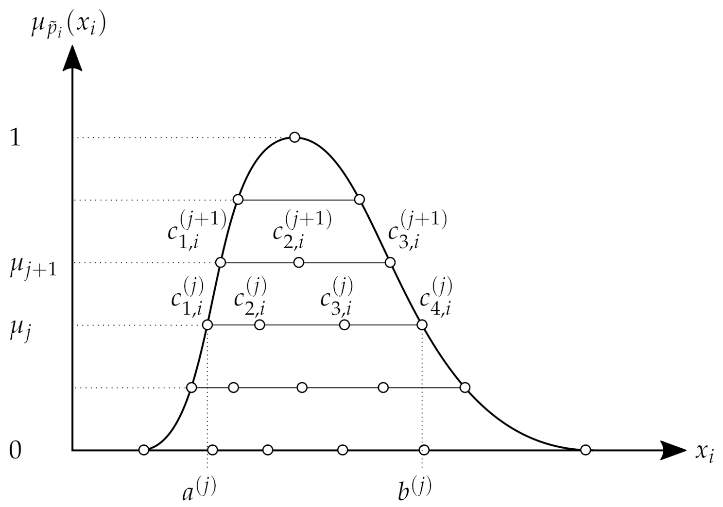
Firstly, the
-axis is subdivided into
m intervals of length
(see
Figure 2), resulting in
membership levels and their corresponding discrete values
Secondly, each fuzzy number
is decomposed into
-cuts, leading to
where each set
consists of the intervals
- II
Transformation of Input Intervals
The intervals
of each level of membership
are transformed into arrays
of the form
with
and
- III
Model Evaluation
The evaluation of the given fuzzy-parameterized system expressed by the functional
F can be carried out by evaluating each column of the arrays separately using the means of classical arithmetic embedded in deterministic solvers. The output
then can be combined into the arrays
, where the
kth element
is determined by
with
as the
kth element of
.
- IV
Re-Transformation of the Output Array
Re-transforming the arrays
according to the recursive formulas
gives the decomposed representation of the fuzzy-valued output
, expressed by the set
- V
Re-Composition of Output Intervals
By recomposing the intervals of the set Q according to their levels of membership , the fuzzy representation of can be obtained.
2.3. Analysis of the Fuzzy-Valued Output
For the quantification of each individual influence mentioned above, a general methodology is proposed in [
11]. Additionally, to re-transform the output array
as explained in step IV of
Section 2.2, its values can be used to determine the gain factors
with
The values and are the lower and upper bounds of the Interval , and and denote the -th and -th element of , respectively.
To obtain a non-dimensional form of the influence measures with respect to the different physical dimensions of
, the standardized mean gain factors
can be determined as an overall measure of influence according to
Finally, the degrees of influence
as a relative measure of influence can be determined via
where
3. Results
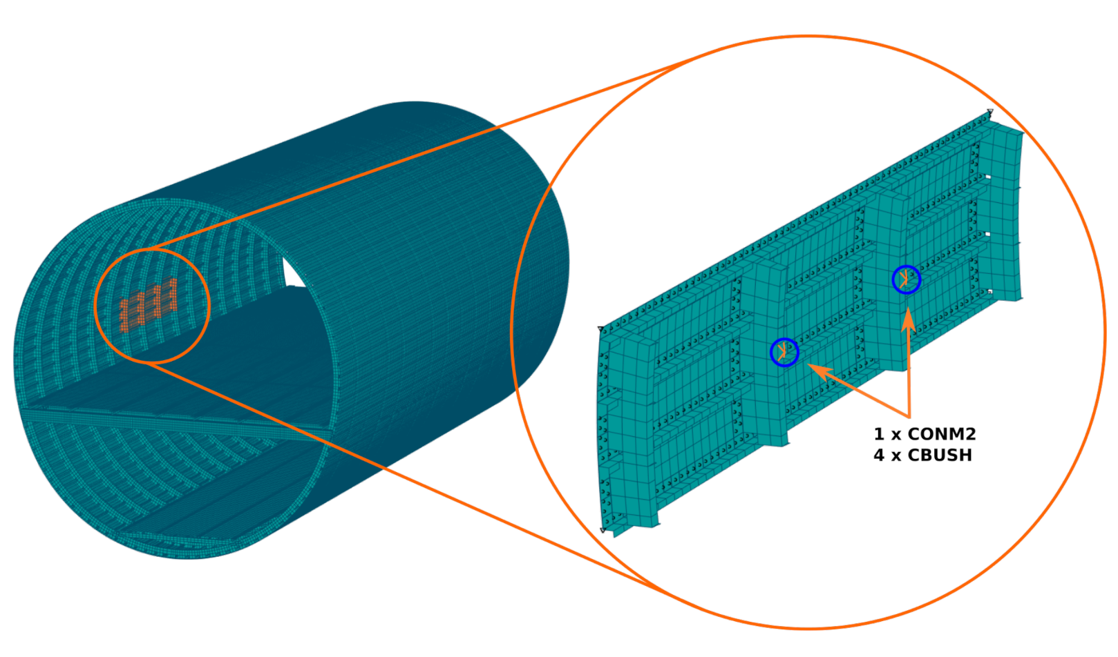
In order to assess the influence of parametric uncertainties from linking elements in airframe structures during vibro-acoustical analyses, a small fuselage panel was isolated from the geometry of the Acoustic Flight-LAB Demonstrator to help to identify the impact of selected masses in a limited domain (see
Figure 3).
3.1. Test Setup
The test setup consists of a panel, which comprises a skin field of approximately 50 cm × 160 cm stiffened by four frames as well as four stringers. It is simply supported at its corners and two generic masses of m = 1 kg are attached to the middle of the two innermost frames via four spring-dashpot elements. The Finite Element representation of the given structure is composed of elements formulated by the numerical solver MSC.NASTRAN, Version 2018. The primary structure is defined by CQUAD4-elements referring to PSHELL-cards, and the attached secondary masses are discretized by CONM2- and CBUSH-elements and their corresponding PBUSH-entries. For further details on the element definitions used in MSC.NASTRAN, please refer to the MSC.NASTRAN Quick Reference Guide [
12].
The uncertain properties for the mass of each CONM2-element and the stiffness as well as damping coefficients for the PBUSH-cards can be found in
Table 1.
3.2. Simulation Results
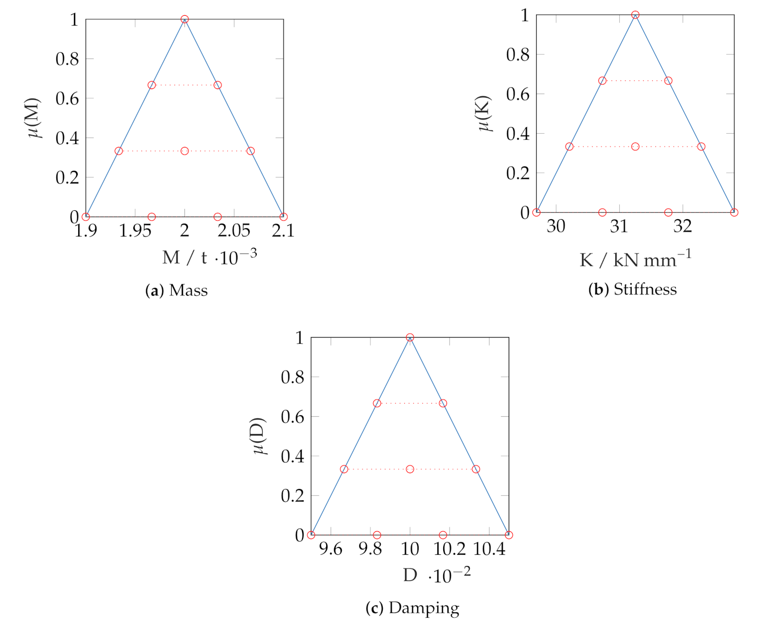
The decomposition of the uncertain parameters for mass, stiffness, and damping according to
Section 2.2 using four
-cuts leads to the fuzzy representation depicted in
Figure 4. Subsequently, a total of 100 deterministic combinations is generated which are used for the following modal and frequency response analyses. In the latter analysis the orthogonal displacement of each node located on the skin will be taken into account to obtain a measure for the vibro-acoustical sound transmission through the panel.
3.2.1. Modal Analysis
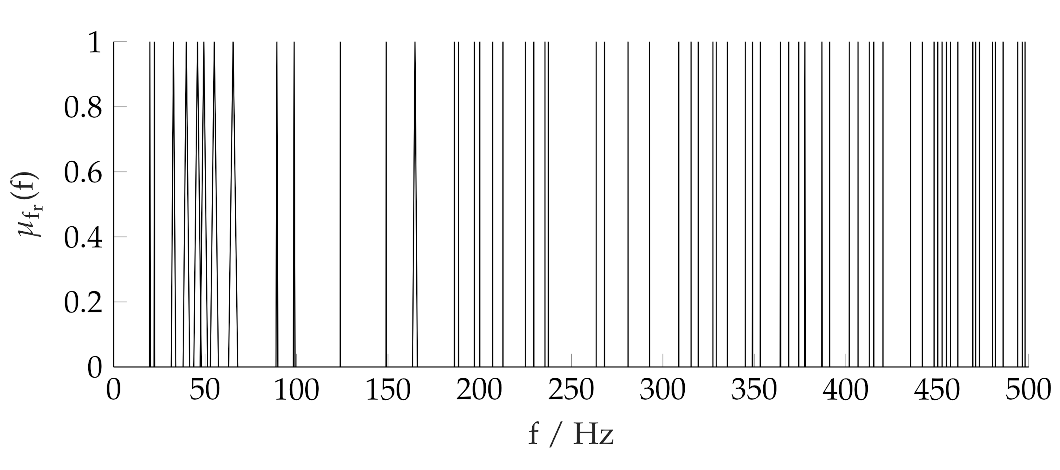
The modal analysis yields 64 modes in the frequency range of 10 Hz to 500 Hz, which are shown in a fuzzy representation in
Figure 5.
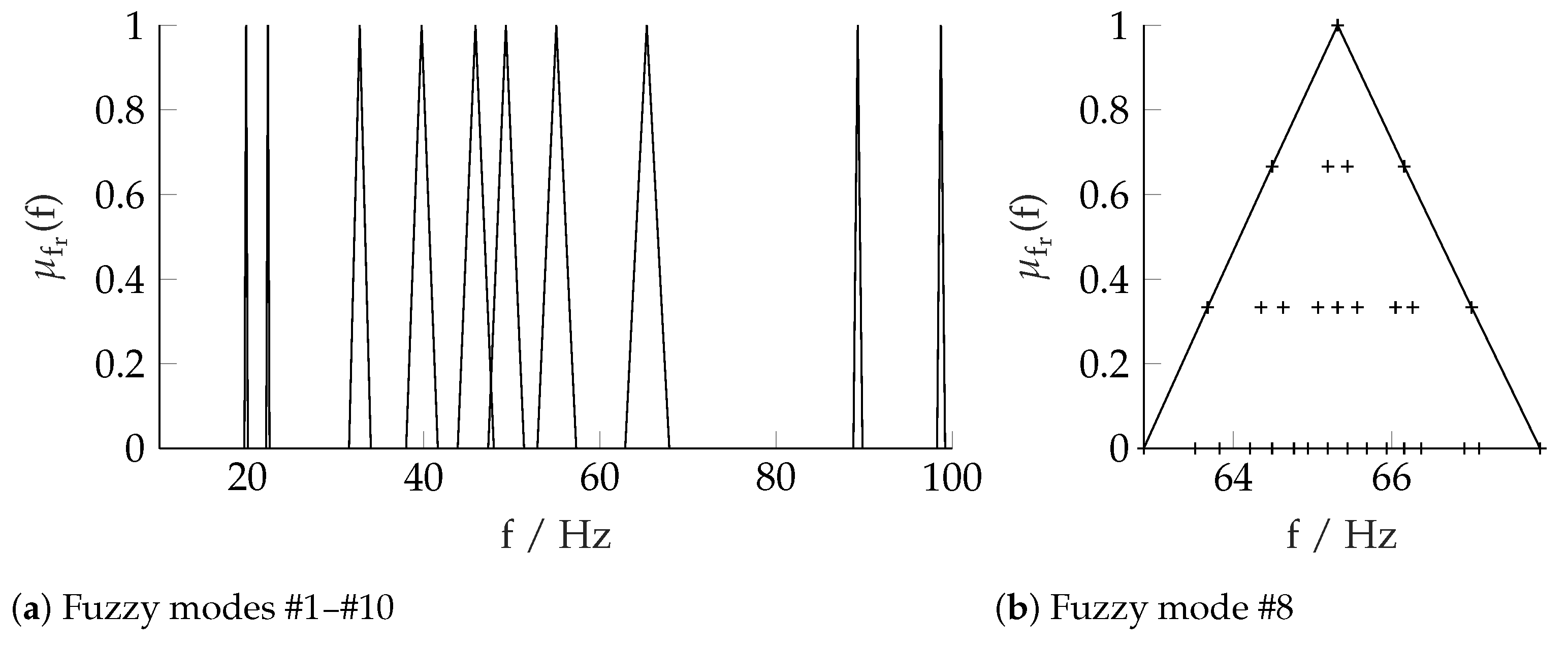
For the sake of clarity, only the fuzzy results of the modes #1 to #10 are depicted in
Figure 6a. Obviously, the fuzziness of the input parameters has the biggest impact on modes #3 to #8, resulting in an area of frequencies from about 30 Hz up to 70 Hz in which an exciting frequency under some unfavorable parameter combinations most certainly will match a resonant frequency of the structure. For example, the 8th mode spans from 63 Hz to 68 Hz (see
Figure 6b, and each cross indicates the result of a deterministic parameter combination).
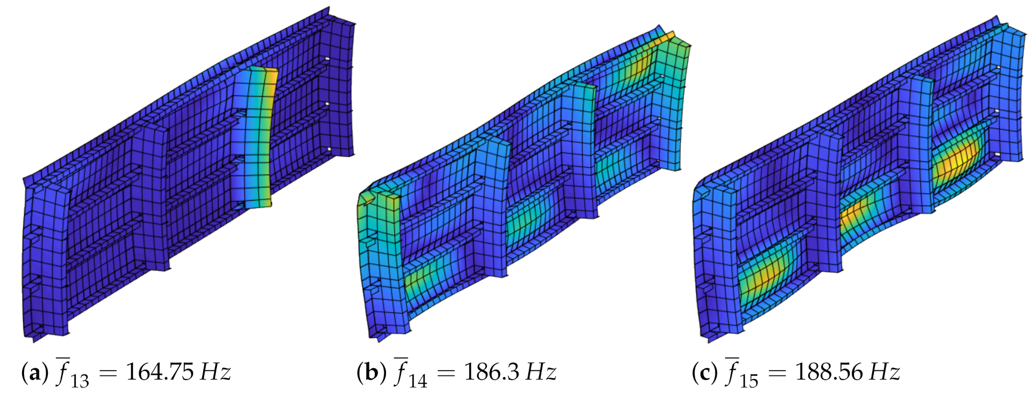
Additionally, from
Figure 7, it can be seen that the transition from global to local skin modes occurs from mode #13 to mode #14, hence the assumption can be made that parametric uncertainties in non-structural masses most likely will have a bigger effect on the structural response below the first skin mode than above.
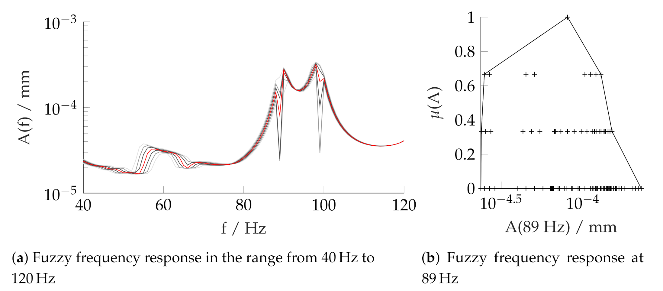
3.2.2. Frequency Response Analysis
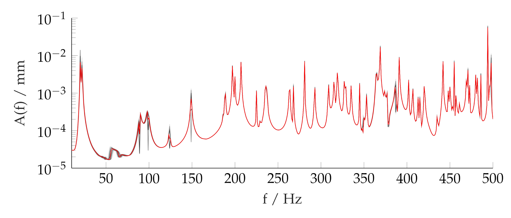
The results from the frequency response analyses are shown in
Figure 8 and
Figure 9. The red line represents the crisp result, where the membership is
. The grey lines edge the upper and lower bounds of each
-level, where the color gradient represents the membership value. Throughout the full frequency domain, the impact of the uncertainties is observable but with the supplementing information obtained during the modal analysis, it is obvious that the fuzziness of eigenfrequencies and the fuzzy frequency response are correlated.
3.3. Sensitivities
As seen in the preceding section, the fuzzy results of eigenfrequencies and frequency response only represent the overall influence of the uncertain parameters , , and combined. However, there is evidence that each model parameter contributes differently to the overall degree of fuzziness, depending on the analyzed frequency as well as the parameter definition.
Applying the procedure of
Section 2.3 the degrees of influence for the three parameters are obtained.
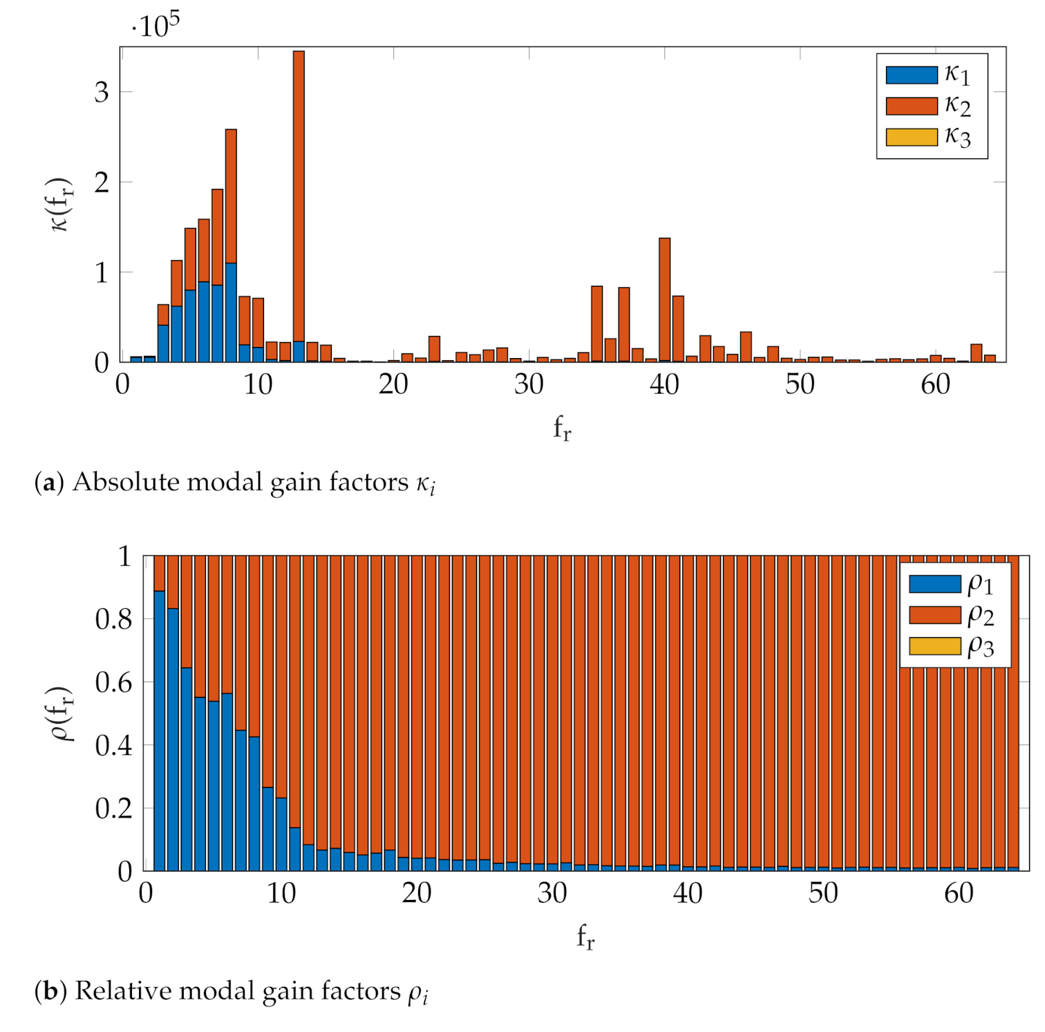
3.3.1. Modal Analysis
In
Figure 10, the overall influence of both the parameters mass and stiffness,
and
, respectively, in the modes below the first skin mode #15 stands out. Additionally, a shift from a mass-dominated relative gain factor towards a stiffness-dominated relative gain factor can be observed: A steep drop from about 90% mass influence at mode #1 to about 90% stiffness influence at mode #15, from where the relative influence of
still decreases, but with a much smaller rate. The fact that damping does not contribute to the overall influence is reasonable, since in eigenvalue analyses only the mass and stiffness matrices are taken into account.
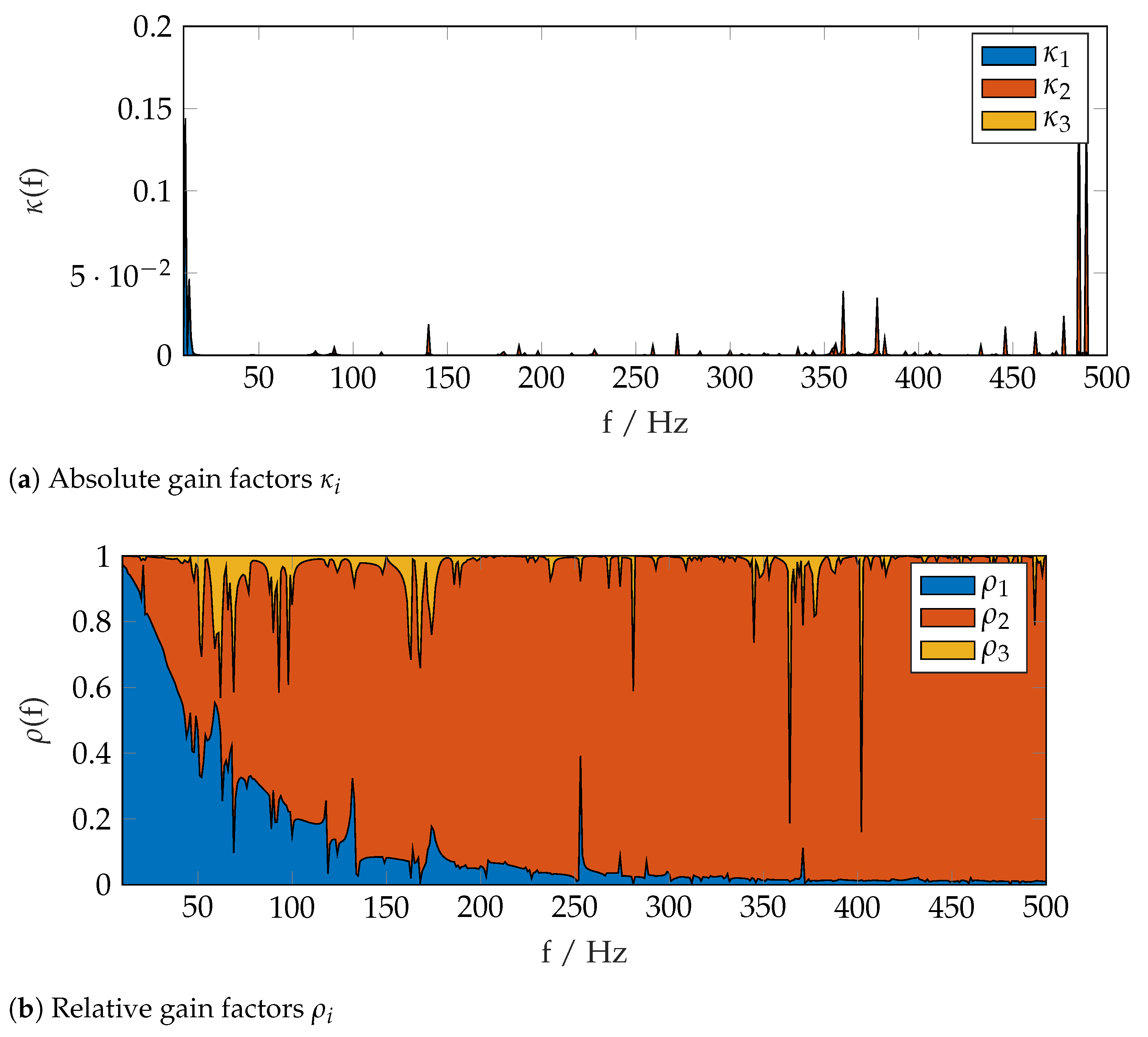
3.3.2. Frequency Response Analysis
The relative influence of mass and damping,
and
, respectively, as shown in
Figure 11 is comparable to the results obtained from the preceding modal analysis, with the exception that now the damping contributes to the global uncertainty as well. A clear trend for damping as in the above mentioned transition from mass to stiffness domination throughout the frequency domain is not observable; nevertheless, it should be noted that the overall relative contribution of structural damping in the linking elements is rather low when compared to the other two parameters.
4. Discussion
The implementation of the fuzzy arithmetic for the current numerical test set-up of a structure with three uncertain parameters and three -cuts results in a total number of investigated system realizations of 100. Each combination is explicitly allocated in the response spectrum and is used to calculate other informative values such as sensitivities and contributing factors. In contrast to the Monte Carlo method with thousands of necessary realizations, the fuzzy arithmetic will cover the full response spectrum of the uncertain system with a manageable number of parameter combinations. In particular, the maximum–minimum interval on the lowest membership level, in other words, the least possible parameter values when applying a pure stochastic method, are automatically part of the structured solution.
However, the number of realizations of a system grows exponentially with the number of parameters and the number of -cuts. For example, adding a fourth parameter to the problem will result in 354 different parameters combinations to be solved. Alternatively, the addition of another -cut to the three existing parameters will result in additional 125 combinations. Although the Fuzzy Arithmetic has its significant advantages over the Monte Carlo method, it rapidly will lose the advantage of cost-efficiency with an increasing number of fuzzy parameters.
Therefore, when applying fuzzy arithmetic to a problem, it might be necessary to limit the system’s complexity either by reducing the number of uncertain parameters or by reducing the size of the model itself. Further research in this regard has been conducted and the means to reduce the computational effort have been developed, such as the elimination of recurring permutations, the treatment of single occurrences of variables through interval arithmetic, and automatic differentiation to test for monotonicity of a model as proposed by Klimke [
13]. Recent extensions of the fuzzy arithmetic have been introduced by Mäck et al. [
14] to perform a structural optimization with uncertain constraints and finally to quantify the fuzziness of complex systems by using multifidelity approaches as shown by Biehler et al. in [
15].
5. Conclusions
Fuzzy arithmetic has been implemented successfully for an aircraft panel with uncertain parameters within its secondary structure. For the current application, it has been shown that this method provides a means to identify structural sensitivities regarding mode eccentricities and response behavior when subjected to external forces. Dominant parameters can be specified for each frequency domain, allowing the alteration of selected structural components and properties towards a more favorable vibro-acoustical configuration in a subsequent step.
Author Contributions
This article represents the collective work of three authors. Conceptualization, J.S.; methodology, S.L.; software, J.S.; validation, J.S.; formal analysis, J.S.; investigation, J.S.; resources, J.S.; data curation, J.S.; writing—original draft preparation, J.S.; writing—review and editing, J.S. and S.L.; visualization, J.S.; supervision, S.L. and O.v.E.; project administration, J.S. and S.L.; funding acquisition, S.L. and O.v.E. All authors have read and agreed to the published version of the manuscript.
Funding
This work was made possible by the aviation research program LuFo V-2 FlightLAB. The authors gratefully acknowledge the project funding by the Federal Ministry for Economic Affairs and Energy due to an act of the German Parliament (project funding number 20K1511F).
Acknowledgments
The authors would like to thank Martin Wandel from Airbus Group SE for providing the Finite Element, odel of the Acoustic FlightLAB Demonstrator.
Conflicts of Interest
The authors declare no conflict of interest.
References
- Thomas, C.; Scheel, H. Kabinenakustik in der Luftfahrtforschung. In Proceedings of the Deutscher Luft- und Raumfahrtkongress 2018, Friedrichshafen, Germany, 4–6 September 2018. [Google Scholar]
- Omais, M.; Biedermann, J.; Wandel, M. From engine integration to cabin noise: Drivers to accurate interior noise evaluations. In Proceedings of the INTER-NOISE 2016, Hamburg, Germany, 21 August 2016. [Google Scholar]
- Hesse, C.; Biedermann, J. Vibroacoustic Evaluation and Optimization of Aircraft Cabin Concepts—A Systems Engineering Framework. In Proceedings of the INTER-NOISE 2019, Madrid, Spain, 30 September 2019. [Google Scholar]
- Seidel, J.; Lippert, S.; von Estorff, O. Über den Einfluss nicht-struktureller Massen auf die Vibroakustik gerippter Strukturen. In Proceedings of the DAGA 2018, München, Germany, 19–22 March 2018. [Google Scholar]
- Seidel, J.; Lippert, S.; von Estorff, O. Vibroacoustical sensitivities of stiffened structures due to attached mass-spring-dampers with uncertain parameters. In Proceedings of the INTER-NOISE 2019, Madrid, Spain, 30 September 2019. [Google Scholar]
- Wandel, M.; Grund, V.; Biedermann, J. Validierung eines vibroakustischen Simulationsmodells einer Flugzeugstruktur im mittleren Frequenzbereich. In Proceedings of the Deutscher Luft- und Raumfahrtkongress 2018, Friedrichshafen, Germany, 4–6 September 2018. [Google Scholar]
- Seidel, J.; Lippert, S.; von Estorff, O. Verbund Flight-LAB: Abschlussbericht für den Berichtszeitraum 01.07.2016-30.09.2019 zum Vorhaben FlightLAB-DYMAV/Zuwendungsempfänger: Technische Universität Hamburg-Harburg; Projektleiter: Prof. Dr. Ing. Otto von Estorff; Technical Report; Technische Universität Hamburg-Harburg: Hamburg, Germany, 2020. [Google Scholar]
- Zadeh, L.A. Fuzzy Sets. Inf. Control 1965, 8, 338–353. [Google Scholar] [CrossRef] [Green Version]
- Zadeh, L.A. Fuzzy Logic. Comput. J. 1988, 21, 83–93. [Google Scholar] [CrossRef]
- Zimmermann, H.J. Fuzzy Set Theory—In Addition, Its Applications; Springer Science + Business Media: New York, NY, USA, 2001. [Google Scholar]
- Hanss, M. Applied Fuzzy Arithmetic; Springer: Berlin/Heidelberg, Germany, 2005; pp. 99–125. [Google Scholar]
- MSC Nastran 2018 Quick Reference Guide; MSC Software Corporation: Newport Beach, CA, USA, 2018.
- Klimke, A. An efficient implementation of the transformation method of fuzzy arithmetic. In Proceedings of the 22nd International Conference of the North American Fuzzy Information Processing Society, Chicago, IL, USA, 24–26 July 2003. [Google Scholar]
- Mäck, M.; Caylak, I.; Edler, P.; Freitag, S.; Hanss, M.; Mahnken, R.; Meschke, G.; Penner, E. Optimization with constraints considering polymorphic uncertain-ties. Special Issue: Polymorphic Uncertainty Modelling for Numerical Design of Structures—Part I. Surv. Appl. Math. Mech. GAMM Mitteilungen 2019, 42, e201900005. [Google Scholar] [CrossRef] [Green Version]
- Biehler, J.; Mäck, M.; Nitzler, J.; Hanss, M.; Koutsourelakis, P.S.; Wall, W.A. Multifidelity approaches for uncertainty quantification. Special Issue: Polymorphic Uncertainty Modelling for Numerical Design of Structures—Part II. Surv. Appl. Math. Mech. Gamm Mitteilungen 2019, 42, e201900008. [Google Scholar] [CrossRef]
| Publisher’s Note: MDPI stays neutral with regard to jurisdictional claims in published maps and institutional affiliations. |
© 2021 by the authors. Licensee MDPI, Basel, Switzerland. This article is an open access article distributed under the terms and conditions of the Creative Commons Attribution (CC BY) license (https://creativecommons.org/licenses/by/4.0/).


