Article

Self-Oscillations of The Free Turbine Speed in Testing Turboshaft Engine with Hydraulic Dynamometer †

1
Department of Automatic Security Systems and Information Technologies, National University of Civil Defense of Ukraine, 61023 Kharkiv, Ukraine
2
Aircraft Engines Design Department, N. E. Zhukovsky National Aerospace University Kharkiv Aviation Institute, 61070 Kharkiv, Ukraine
3
Department of Design and Strength of Aircraft and Engines, Ivan Kozhedub Kharkiv National University of the Air Force, 61023 Kharkiv, Ukraine
*
Author to whom correspondence should be addressed.
This paper is an extended version of our paper published in AVT-357 Research Workshop on Technologies for future distributed engine control systems (DECS) hosted by the Science and Technology Organization in NATO during 11–13 May 2021.
Aerospace 2021, 8(4), 114; https://doi.org/10.3390/aerospace8040114
Submission received: 10 November 2020 / Revised: 2 March 2021 / Accepted: 14 April 2021 / Published: 17 April 2021
(This article belongs to the Special Issue Technologies for Future Distributed Engine Control Systems)

Abstract

:
Self-oscillations are one of the common problems in the complex automatic system, that can occur due to the features of the workflow and the design of the governor. The development of digital control systems has made it possible to damp self-oscillations by applying complex control laws. However, for hydromechanical systems, such way is unacceptable due to the design complexity and the governor cost. The objective of this work is to determine the parameters of the hydromechanical free turbine speed controller, ensuring the absence of self-oscillations during ground tests of the turboshaft engine with a hydraulic dynamometer. The TV3-117VM engine (Ukraine) with the NR-3VM regulator pump (Ukraine) was selected as the object of the study. However, self-oscillations can also occur in any modifications of the TV3-117 engine with any NR-3 regulator pump. The results of the research may be of interest to engineers and scientists who investigate the dynamics of automatic control systems for similar engines. The paper analyses the nonlinear features of the empirical characteristics of the FTSC leading to self-oscillations of the engine speed. The authors propose the mathematical model of the automatic control system dynamics, which takes into account all the features of the engine and regulator pump. It is shown that the load characteristics of the water brake and the helicopter main rotor can differ significantly. Research of the dynamic characteristics of the TV3-117VM engine was carried out. The analysis showed a good agreement between the calculation results and the field test results, and made it possible to determine the parameters of the controller, which lead to self-oscillations during test. Two cases are considered. The first case includes ground tests of the engine with a water brake; the second case—flight tests of the engine as part of the helicopter’s power plant. The data obtained make it possible to develop recommendations for adjusting the hydromechanical governor without testing it on the engine.

1. Introduction

Ground testing of aircraft gas turbine engines is an important part of their life cycle. The facilities with water brakes are used for testing of turboshaft engines. The point of interest for those tests in steady states is to verify the engine outputs the required power at all modes. Usually, the speed controller in these modes maintains constant fuel consumption. When self-oscillations appear, the fuel control unit is changed. Therefore, the dynamics of the engine under steady-state conditions are given close attention exclusively at the design and development stages. Not enough attention is paid to this problem at manufacturing and repair stages of engines and units. In reality, the controller continuously changes the control action on the motor and counteracts rapid external disturbances. Such operation of the controller is not noticed when automatic control system (ACS) operates correctly. But if the characteristics of the ACS elements do not correspond to the calculated data, then this can result in oscillations or unstable operation. This issue is especially relevant for turboshaft engines with hydromechanical automatic control system, the parameters of which can vary in a fairly wide range.
During ground tests of the TV3-117 turboshaft on a non-automated water brake unit, the continuous oscillations of free turbine (FT) rotor speed and parameters of the gas generator are often detected. Typically, these oscillations occur in the operation area of the free turbine speed controller (FTSC). In the literature, such steady-state oscillations in automatic control systems are called self-oscillations. Elimination of the self-oscillations on such engine type is carried out by replacing the fuel supply controller. Complete disassembling of the governor and geometric measurement of all its parts do not enable to troubleshoot the defect. It should be noted that when the engine is operating as part of a helicopter power plant, the self-oscillations are much less frequent. Ground tests of a turboshaft engine are carried out on water brake units. In this case, the plant is a free turbine connected to the water brake (FT + WB). When the engine operates as a part of the helicopter power plant, the plant is a free turbine connected to the main rotor of the helicopter (FT + MR). The load characteristics of the water brake and the main rotor are very different. In addition, the characteristics of controllers and engines also differ from each other. With unfavourable combinations of characteristics, the operation of the automatic control system becomes unsatisfactory. The paper presents the experimental load characteristics of the water brake and the helicopter main rotor. Their essential difference is shown. Experimental studies of static characteristics of free turbine speed controllers are presented. It is shown that characteristics of the controllers can have different types of non-linear behaviour, which made that the analysis of the engine characteristics required to perform deep analysis of the root cause. It is shown that the dynamic parameters of engines of the same type are different. A mathematical model of the free turbine speed ACS is developed, taking into account the empirical characteristics of the controller, engine and plant. Numerical studies were carried out for both systems. The permissible values of the nonlinear behaviour of the controller characteristics are determined, which ensure the absence of self-oscillations for the TV3-117 turboshaft. Recommendations for the manufacturer on the choice of parameters of the free turbine speed controller have been developed.

2. Literature Review

The object of study is a hydromechanical system for automatic control of free turbine speed of helicopter turboshaft. The TV3-117 engines with fuel supply controller NR-3 are considered. The problem induces self-oscillations and unstable operation during ground tests of the engine with water brake units. The relevance of the topic is due to a large number of currently used engines with hydromechanical control systems (T700-GE-700 (USA); MTM385R (France); TV3-117 (Ukraine)). The results obtained can be useful for a complete understanding of the processes in automatic control systems.
The works in such areas as transient modes of the gas turbine engine, dynamics of the engine governor at small deviations and nonlinear dynamics of the automatic control system belong to the methodological basis of this research. Transients are understood as starting, accelerating and decelerating modes. In [1,2], the theory and methods of the automatic control systems analysis of aircraft gas turbine engines in transient operation under ground and flight conditions are presented. The external and internal factors influencing the dynamics of engines of different schemes are considered. The possibility of using the theory of similarity in the analysis of transient processes is shown. The principles of rational regulation of gas turbine engines in transient modes are grounded. The presented methods make it possible to determine the parameters of the engine at various points to study the dynamics of automatic control systems in steady-state conditions. General approaches to studying the dynamics of the automatic control system near the points of steady-state regimes are described in [3,4]. The equations of the engine dynamics, its own stability and influence of external conditions on the dynamic parameters are considered. The structural and structural-dynamic diagrams of various automatic control systems are shown. The presented methods are the basis for studying the dynamics of automatic control systems in the packages of modern applied programs.
The works devoted to the nonlinear dynamics [5,6] discover the theoretical foundations of self-oscillations of the automatic control systems. From those, we can figure out that the oscillations in the process control loops is a very common problem. The oscillations often indicate a more serious problem than irregular fluctuations. The authors describe that the causes of self-oscillations are essentially nonlinear features of the characteristics of the ACS elements. These features include dead-bands, discontinuities and breaks in the characteristics of elements. A discontinuity should mean a stepwise change in a parameter, and the break is a sharp change in the inclination angle of the element characteristic.
Much attention is paid to developing the theoretical foundations for analysing stability and self-sustained oscillations in modern nonlinear systems. Paper [7], for example, the authors consider the possibility of developing self-oscillations in nonlinear automatic control systems based on the analysis of real roots of specially constructed algebraic equations. This approach really expands the capabilities of the preliminary analysis of the origination of self-oscillation but does not allow for taking into account the nonlinear features of the real units. Paper [8] investigates the nonlinear oscillatory processes in systems with variable parameters and a delay link. The presence of a delay link complicates the task even more. A method is proposed to determine the conditions for the self-oscillations. However, in general, a linear problem with a delay link is considered. The stepwise change in the controller gain at the points under consideration is ignored.
In practice, the diagnostics issues of self-oscillations are very important. The root causes that lead to self-oscillations, and the methodological foundations of diagnostics of self-oscillations in industrial processes are discussed in detail in [9]. Oscillations can be caused by too high gain of controller, oscillatory disturbances, or interactions. A very common cause of self-oscillation is friction in the control valves. The authors compile the goals of diagnostics of self-oscillations, discuss the methods for identifying oscillations in transient processes. The experimental study of self-oscillation diagnostics was reflected in the works [10,11]. Paper [10] reflects the influence of sticking of the control valve on the non-linearity of the system. It is shown that nonlinear characteristics of the valve can lead to instability and origination of self-oscillations of the control system. However, the methodology for diagnosing this defect is not fully studied in the work. Paper [11] provides a frequency method for analysing the sticking of a control valve in the multi-loop control systems. This paper focuses on the frequency analysis of self-oscillations caused by valve sticking. A mechanism for compensating for self-oscillations, that is adjusting the external and internal controller, is suggested. Paper [12] notes that any control system contains one or several essentially connected nonlinear elements. The presence of such elements in automatic control systems causes such unfavourable effects as a decrease in the stability margin, the appearance of self-oscillations and an increase in the static error. The article proposes a software module for dead-band compensation. The possibility of compensating for the discontinuity in characteristics of controller is not considered.
In works [13,14], low-frequency oscillations are considered when testing the turboshaft engines with water brake units. As a result of the research, it was found that the cause of the excitation of low-frequency oscillations are fluctuations in the fluid flow in the water brake. In [13], a model is presented for calculating the excitation of low-frequency oscillations in the system for measuring the reactive torque by high-frequency oscillations of the fluid flow pressure. However, this model does not allow explaining the occurrence of self-oscillations in the automatic control system of free turbine speed and the absence of oscillations in the area of operation of the gas generator speed controller. Paper [14] presents the results of studies of inducing self-oscillations during testing of high-power turboprop engine with water brake. One of the reasons for the occurrence of fluctuations in the free turbine speed is the cavitation of the working fluid entering the water brake. The authors highlight as well that the possible reason for the low-frequency oscillations in the free turbine speed is the off-design operation of the automatic control system. But this issue has not been fully investigated.
When designing the automatic control systems of the TV3-117 turboshaft, it was assumed that the characteristics of the free turbine speed controller were linear. However, [15] presents the empirical characteristics of the NR-3 regulator-pump and shows that they are nonlinear and contain discontinuities and breaks. Such defects cannot be detected during routine factory tests of the unit. Also, as noted above, such defects can lead to inducing self-oscillations or unstable operation of the automatic control system. The influence of the FTSC characteristics on inducing self-oscillations has not been studied. Paper [16] shows that when testing a turboshaft engine with a water brake, and when the engine operates on a helicopter, the controlled system is different. This difference is determined by the different load characteristics of the helicopter main rotor and water brake system. The authors propose a method for emulating the main rotor characteristics on a water brake installation by means of automation. It is shown that it is not correct to test a turboshaft engine with a water brake unit without load automation. A significant difference in the characteristics of the plants can cause unsatisfactory operation of the controller. Paper [17] raises the problem of developing water brake units with the ability to simulate the characteristics of a helicopter main rotor and ship propellers. However, no specific data on the ways to achieve the specified characteristics, calculation results or experimental data are provided. Paper [18] addresses the use of a turboshaft as an auxiliary engine of a hybrid power plant of an aircraft. The operation of the auxiliary power plant of the aircraft implies deep throttle modes, in which self-oscillations of free turbine speed are most often possible. The authors do not consider the possible unsatisfactory operation of the automatic control system at deep throttle modes of the engine operation. In [19], the performance of a turboshaft engine for helicopter applications operating at variable shaft speed is investigated without taking into account the influence of the rotor inertia on the dynamics of the power plant. In [20], a methodology is presented for determining the optimal rotational speed of a variable RPM main rotor. The issues of matching the characteristics of the main rotor with the automatic control system remained unsolved. In [21], a simulation analysis of the impact of a complex electromagnetic environment on a helicopter engine was carried out. No change in the dynamic parameters of the engine was detected. In [22], research of turboshaft engine power loss was carried out using statistical analysis. The use of averaged data in the analysis does not allow identifying the problems of control system dynamics. The authors of [23] carried out studies of a health-monitoring system for a specific type of turboshaft engine based on flight data which detected the fluctuations in engine parameters at a reduced speed. The analysis of the reasons that caused the fluctuations was not carried out. Similar results are presented in [24]. In [25], the influence of rapid changing external conditions on the gas-dynamic stability of a helicopter engine is shown. But, the stability of the automatic control system was not considered. In [26], the analysis of self-oscillations in various dynamical systems does not take into account the features of specific systems. Study of the fuel efficiency of the GE T700 turboshaft engine with a wide speed range of helicopter main rotor was carried out in [27]. The possibilities of changing the dynamics of engine and helicopter were not considered. In [28], a model of a self-tuning speed controller of power turbine is presented. The linear models of the engine and fuel supply unit used in the research do not allow to take into consideration nonlinear sections of characteristics in transients. In [29], the static characteristics of the helicopter are presented when improving the main rotor. Changes in the dynamics of the helicopter power plant were not described. In [30], the optimisation of the rotor blades of the helicopter is performed. The change in the dynamic characteristics of the rotor was not considered. Paper [31] considers the problems of the power plant when turning the rotor of the propeller, but the problems of the power plant dynamics itself are not analyzed.
The authors of [32] consider the optimisation of the steady-state operating modes of a turboshaft and electric engine of a hybrid power plant, but do not take into account the dynamic processes associated with loading and unloading the power turbine. A model of a turboshaft engine based on the empirical controller characteristics is presented in [33], where the calculated dynamic parameters have a significant (up to 8%) error. The effect of erosive wear out on the compressor characteristic of the TV3-117 engine is given in [34] without taking into account the effect on the dynamic parameters of the gas generator. From the data presented in [35], it follows that failures of the measurement system can lead to the development of the self-oscillations. To prevent possible failures in the measuring system, a predictive controller was proposed in [36] but methods for preventing self-oscillations were not studied.
Paper [37] considers the problems of the dynamics of a helicopter engine during flight tests using the example of the T700-GE-701 turboshaft engine. [37] notes the possibility of the occurrence of prolonged oscillations of the helicopter main rotor in flight, but does not consider ground tests of the engines on a hydraulic dynamometer. One of the ways for solving the problem of dynamics is the use of digital controllers [38]. The small-sized YT700 engine manufactured by General Electric is considered. [38] shows the possibilities of improving the control dynamics of the free turbine in relation to the original governor, but does not address the problem of the occurrence of self-oscillations. Work [39] considers the problems of dynamics for the hydromechanical ACS in multi-engine helicopters. It describes the impact of the gain and hysteresis of the controller on the dynamics of the ACS. However, the influence of the defects of the controller characteristics on the ACS dynamics is not considered.
The analysis of the workflow and automatic control systems of such engines as T700-GE-700 (USA), MTM385R (France), TM333-1M (France), RTM322-01 (France), TV3-117 (Ukraine) showed that in the operating area, the FTSC has a problem of inducing self-oscillation. The nonlinearity of the FTSC characteristics and changes in dynamic parameters of the engine and plant can be the reasons for inducing and developing self-oscillations of turboshaft engine during ground tests and flight.
Thus, there is a problem of studying the dynamics of a turboshaft in ground testing with hydraulic dynamometer and when the engine operates as part of helicopter power plant.

3. Research Objectives

  • To establish the causes of occurrence and development of the self-oscillations of free turbine and gas generator rotor speed during ground testing of TV3-117 turboshaft with water brake installation.
  • Studying the influence of the dynamic parameters of automatic control system of free turbine speed (ACS (nFT)) of TV3-117 turboshaft with NR-3 regulator-pump on inducing self-oscillations in the FTSC operating range during ground testing with a water brake and when the engine operates as part of helicopter power plant. Determining the unfavourable combination of the ACS (nFT) dynamic parameters that can induce the self-oscillations.
  • Development of recommendations for ground testing the TV3-117 turboshaft with water brake.

4. Methods

A mathematical model of the ACS (nFT) dynamics of turboshaft engine includes:
  • Dynamic model of the gas generator (GG) rotor;
  • Dynamic model of the FT rotor connected to water brake;
  • Dynamic model of the FT rotor connected to helicopter main rotor;
  • Dynamic model of the FTSC.
At steady-state modes the task of any controller is to ensure the set value of adjustable parameter. Any deviation of the adjustable parameter from the set value is parried by the controller with a corresponding change in the controlling factor. In this case, the ACS dynamics equation is conveniently considered in small deviations relative to the base point.
In the mathematical description of the dynamics of gas generator and free turbine, the following assumptions are accepted [3]:
  • The difference between the inertance of the heat release processes in the combustion chamber in comparison with the inertance of the engine rotors and can be neglected;
  • The inertance of the gas-dynamic processes associated with the accumulation and draining of the working fluid in the engine internal cavities is negligible small;
  • The torque losses associated with an accessories drive and friction in the bearings are negligible.
  • Based on the notes above, the dynamics of the turboshaft engine is determined by the dynamics of the gas generator, free turbine and free turbine controller.

4.1. Dynamic Model of the Gas Generator Rotor

Consider the equation of the rotor dynamics for gas generator:
π I G G 30 d n G G d t = M C M T
where IGG is the equivalent moment of inertia of gas generator, nGG is the rotor speed of gas generator, MT is the turbine torque and MC is the compressor anti-torque.
In general terms, the moments of the turbine and compressor are complex functions:
MT = (nGG; Wf; P0; T0)
MC = (nGG; Wf; P0; T0)
where Wf is the fuel consumption, P0 * and T0 * are the total air pressure and temperature at the engine inlet.
For simplicity, we will assume that engine tests conditions correspond to standard atmosphere. This allows at the initial stage of the study to neglect the influence of changes in P0 * and T0 *.
Given the above assumptions, the Equation (1) is linear and in relative variables takes the form [7]:
T G G n ¯ ˙ G G + n ¯ G G = K G G W ¯ f
where TGG is the time constant of the gas generator, n ¯ G G = Δ n G G n G G   b a s i s is the relative speed of the gas generator rotor, nGG basis is the basis value of the gas generator rotor speed, ΔnGG is the deviation of the gas generator rotor speed from the reference value, n ¯ ˙ G G = d n ¯ G G d t is the relative rotor acceleration of gas generator, W ¯ f = Δ W f W f   b a s i s is the relative fuel consumption, Wf basis is the basis value of the fuel consumption, KGG is the rotor speed gain of the gas generator depending on the fuel consumption.
The time constant TGG of the gas generator can be roughly estimated from a dynamic analysis of ACS(nGG) operation based on the known time value of the partial acceleration performance, which according to the operator manual should be:
  • 9 s–from idle to take-off mode;
  • 4 s–from first cruise to take-off mode;
  • 3–6 s–from idle to right correction.
Consequently, the time constant of the gas generator will be within:
TGG ≈ (1…3), s
In steady states d n ¯ G G d t = 0 and as follows from Equation (4) the gain KGG equals:
K G G = n ¯ G G W ¯ f = Δ n G G Δ W f W f   b a s i s n G G   b a s i s
Thus, the gain KGG can be determined by the engine throttle characteristics (dependence of engine parameters on the GG rotor speed). However, to conduct dynamic studies, the knowledge of the calculated value of the GG gain is not enough. It is also necessary to know the possible range of variation of this gain. Therefore, the KGG value was calculated taking into account the tolerance field for deviation of parameters during engine tests (Figure 1).
When the GG rotor speed decreases, the engine inherent stability decreases [7]. Therefore, the selected design point corresponds to the second cruise mode as the mode with the lowest self-levelling coefficient. For a given tolerance field of the engine throttle characteristic, the gain of GG will be within:
KGG = 0.124…0.189.
An engine with a large gain in fuel consumption will be called ‘sharp’ in the future, and with a small one—‘blunt’.

4.2. Dynamic Model of the Free Turbine Rotor

The dynamic model of the free turbine rotor is presented in detail in [16]. According to [16], the equation of rotor dynamic for the (FT + WB) system is linear and in relative variables takes the following form:
T W B n ¯ ˙ F T + n ¯ F T = K W B / n G G n ¯ G G
where TWB is the (FT+WB) time constant, n ¯ F T is the relative rotor speed of the free turbine, n ¯ ˙ F T = d n ¯ F T d t is the relative rotor acceleration of free turbine, K W B / n G G = Δ n ¯ F T Δ n ¯ G G is the gain of the (FT + WB) rotor speed depending on the rotor speed of the gas generator.
The equation of rotor dynamics for the (FT + MR) system is linear:
T M R n ¯ ˙ F T + n ¯ F T = K M R n ¯ G G
where TMR is the (FT + MR) time constant, K M R = Δ n ¯ F T Δ n ¯ G G is the gain of the (FT + MR) rotor speed dependant on the gas generator rotor speed.

4.3. Dynamic Model of the Free Turbine Speed Controller

The dynamics of the free turbine speed controller is determined by the processes of filling and draining the cavities of the hydraulic drive of main metering valve (MMV) in the regulator-pump. In this case, the equation of linear dynamics for FTSC can be represented as [7]:
T F T S C W ¯ ˙ f + W ¯ f = K F T S C ε ¯
where TFTSC is the time constant of the free turbine speed controller, KFTSC is the FTSC gain, ε ¯ = ( n ¯ F T , s e t n ¯ F T ) is the error signal generated by a tachometer, n ¯ F T , s e t is the relative set value of the FT rotor speed formed by the tuning unit.
The time constant TMMV of the main metering valve (MMV) can be determined by its shift time. Since the dynamics of the free turbine speed controller is described by a linear differential Equation (8) of the first order, for this case the FTSC time constant can be determined by the formula:
T F T S C = T M M V = t R .   M M V 3
where tR.MMV is the MMV shift time under stepped signal of reconfiguration.
According to the manufacturer’s acceptance test protocol, the MMV shift time should not exceed the 4 s limit (usually 2…4 sec), therefore:
T M M V = 2 4 3 = ( 0.66 1.33 ) , sec
The FTSC gain can be determined from static characteristic of the governor:
K F T S C = Δ W f Δ n F T n F T   b a s i s W f   b a s i s
According to the technical specifications for the manufacture, the FTSC gain of the regulator pump can vary within the range: KFTSC = 16…30.
However, as experimental studies show [2] the empirical static characteristics of the FTSC are complex and contain a dead zone (hysteresis) due to friction in the MMV hydraulic actuator, and may also contain non-linear sections—’discontinuities’ and ‘kinks’ (Figure 2) associated with defects in the elements of the regulator.
Consider the movement of the operating point on FTSC characteristic (Figure 3).
Suppose that the steady state is at point ‘1’. In case of a random decrease in a rotor speed, the operational point passes the dead-band at the point that is similar to the calculated one for the hysteresis ( Δ n ¯ ) h y s   c a l c and moves horizontally from point “1” to point “2”. At point ‘2’, the flow mode in the control valve of FTSC is changed, and the operating point passes to point ‘3’. As a result, a stepwise change in fuel consumption is formed—a fuel ‘surge’ by the amount of:
Δ W ¯ f   s u r g e = ( ( Δ n ¯ ) h y s   c a l c ( Δ n ¯ ) h y s   r e a l ) K F T S C
where ( Δ n ¯ ) h y s   c a l c ≈ 0.01 is the relative calculated value of hysteresis defined by specifications, ( Δ n ¯ ) h y s   r e a l is the relative value of hysteresis determined by experiment.
The discontinuity of the FTSC characteristic and fuel ‘surge’ are simulated by the stepped equivalent to dynamic correction of the regulating error:
ε ¯ d y n = ( Δ n ¯ ) h y s   c a l c ( Δ n ¯ ) h y s   r e a l
If the empirical hysteresis equals the calculated one, ( Δ n ¯ ) h y s   r e a l = ( Δ n ¯ ) h y s   c a l c , the dynamic correction is zero ε ¯ d y n = 0). For a one-side ‘discontinuity’ of the characteristic, the dynamic correction is formed when the operational point unilaterally leaves the dead-band, and for a two-side ‘discontinuity’, the correction is formed when the operating point leaves the dead-band in both directions.
Based on the result of mathematical description of the components, we propose the structural-dynamic model of the FT speed control system. Figure 4 shows the scheme of ACS (nFT) with (FT+WB). The scheme of ACS (nFT) with (FT + MR) is similar, except the WB rotor dynamics Equation (6) that is substituted by the MR dynamics Equation (7). The scheme contains three non-linear blocks. The one of them is the block with dead-band allowing to model a hysteresis ( Δ n ¯ ) h y s   r e a l of the FTSC characteristic. Another one is the relay block which provides modelling of a nonlinear dynamic correction ε ¯ d y n of the regulating error and the formation of fuel ‘surge’ in the event of supposed ‘discontinuity’ in the FTSC characteristic. The third is the block for selecting the maximum and minimum values (KFTSC max OR KFTSC min) of the FTSC gain depending on the sign of the error signal ε. This block allows to model the ‘break’ of the characteristic.
Thus, the structural-dynamic scheme takes into account all possible parameters of ACS (nFT).

5. Results and Discussion

For the analysis of the dynamics of ACS (nFT) with the (FT + WB) system, we selected the average values of the component’s dynamic parameters to be studied in the further analysis:
{ K G G = 0.155 ; T G G = 1.2 ,   s e c ; K W / n G G = 2.5 ; T W B = 0.5 ,   s e c ; K F T S C = 21 ; T F T S C = 0.7 ,   s e c ; ( Δ n ¯ ) h y s   r e a l = ( Δ n ¯ ) h y s   c a l c = 0.01 }
As an excitation, a short, one-second change in the FT rotor speed by 2% was applied.

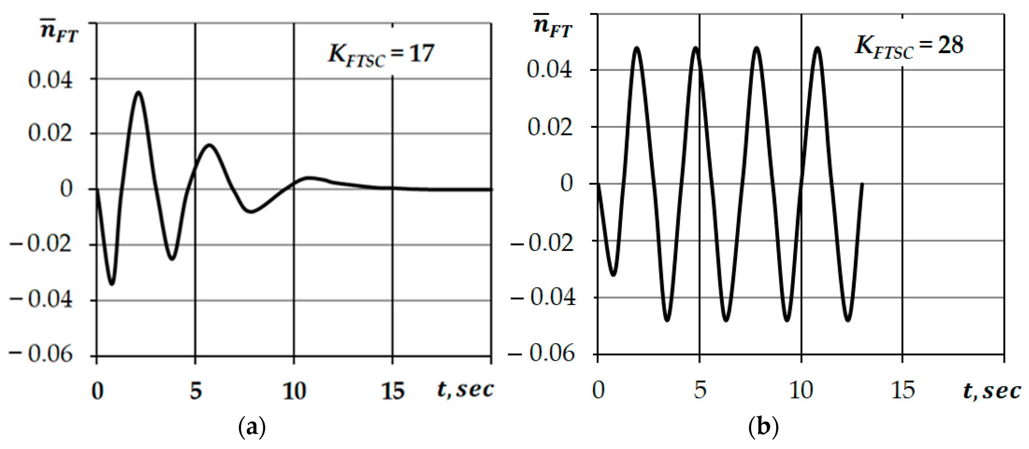
5.1. Influence of FTSC Gain

Figure 5 shows the influence of the FTSC gain on the response of ACS (nFT) with (FT + WB). The parameter values of gas generator and water brake correspond to Equation (11).
Figure 5 shows that with an increase in the FTSC gain, the tendency of ACS (nFT) to oscillate rises sharply. For the (FT + WB) system at the value KFTSC ≈ 17 (Figure 5a), the oscillations decay quickly, but for KFTSC ≈ 28 (Figure 5b), the oscillations become undamped, and if KFTSC > 28, the amplitude of the oscillation continuously increases (the system becomes unstable). However, according to design documentation, the maximum value of the FTSC gain is limited to 30. It lead to unstable work of the automatic control system.

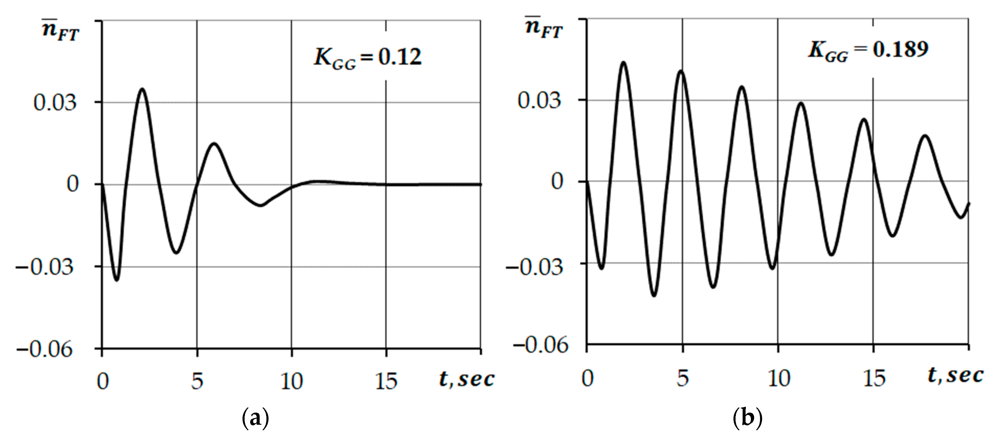
5.2. Influence of GG Gain

The dynamic parameters of the gas generator can also vary within the tolerance range of the throttle characteristics (Figure 1), which will inevitably affect the response of ACS (nFT). As a result, the same controller works in a different way during the testing with different engines.
Figure 6 shows the results of calculating the effect of the gas generator gain on the response of ACS (nFT) with (FT + WB). The values of the parameters of FTSC and WB correspond to Equation (11).
Figure 6 demonstrates that with a ‘blunt’ engine with KGG = 0.12 (Figure 6a), the FTSC with an average dynamic parameters works satisfactorily (the response is damped). In the composition of a ‘sharp’ engine with KGG = 0.189 (Figure 6b) the same controller does not fulfil the requirements (the response does not decay for more than 20 s). Thus, for a specific engine with certain dynamic parameters, the acceptable values of the FTSC gain can be found. Figure 7a illustrates the dependence of acceptable value of KFTSC gain on the KGG gain for different amount of the FTSC hysteresis. The dynamic correction (10) was not taken into account. It is seen that for engine with average level of gas generator gain KGG = 0.155, the FTSC gain should be no more KFTSC ≤ 24.5. Taking into account the hysteresis of the FTSC characteristic, the allowable gain value increases to KFTSC ≤ 28. To ensure stable operation of the ‘sharp’ engine which gains KGG = 0.189, the lower value of the FTSC gain is required—no more KFTSC ≤ 19.
To study the dynamics of ACS (nFT) with an object (FT + MR), the following values of the dynamic parameters of main rotor were chosen as the initial point to make a comparison (excluding dynamic correction Equation (10)):
{ K G G = 0.155 ; T G G = 1.2 ,   s e c ; K M R = 1.55 ; T M R = 1.5 ,   s e c ; K F T S C = 21 ; T F T S C = 0.7 ,   s e c ; ( Δ n ¯ ) h y s   r e a l = 0.01 }
The given values of the parameters correspond to the worst case in terms of the development of self-oscillations. Such a case is the operating mode of the helicopter power plant with a minimum pitch of the rotor blades. When loading the main rotor (the pitch increases), the main rotor gain (Equation (12)) decreases and as a result, the tendency of the automatic control system to develop self-oscillations decreases too.
Figure 7b shows the comparison of the KFTSC values estimated for (FT + WB) and (FT + MR). It is seen that when FTSC operates with (FT + MR), the allowable range is much wider. All the controllers with gain value within the allowable range KFTSC = 16…30, recommended by specifications, operate stable with (FT + MR). At the same time, when FTSC is used with (FT + WB), the controllers that have the gain value KFTSC > 22 can be unstable with an engine which has mean or higher value of gas generator gain (KGG > 0.155).

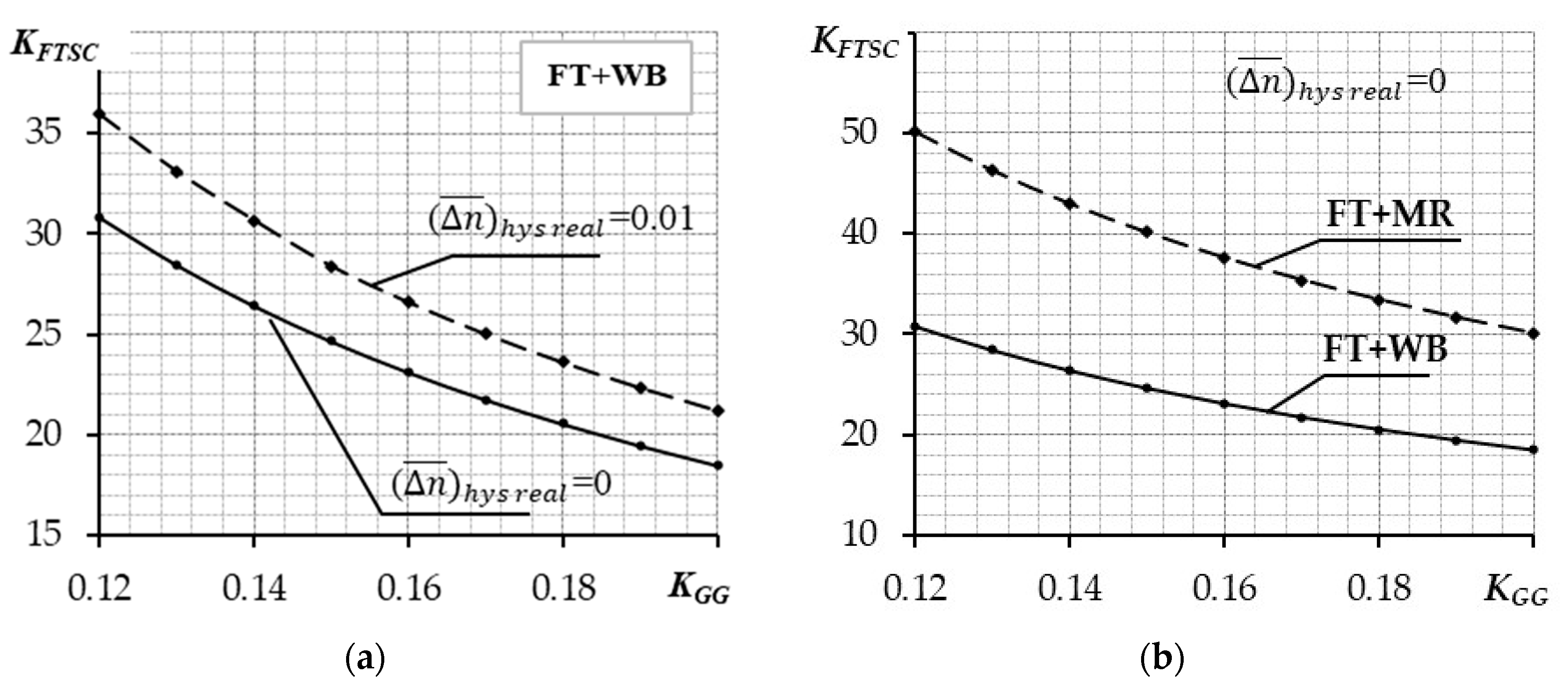
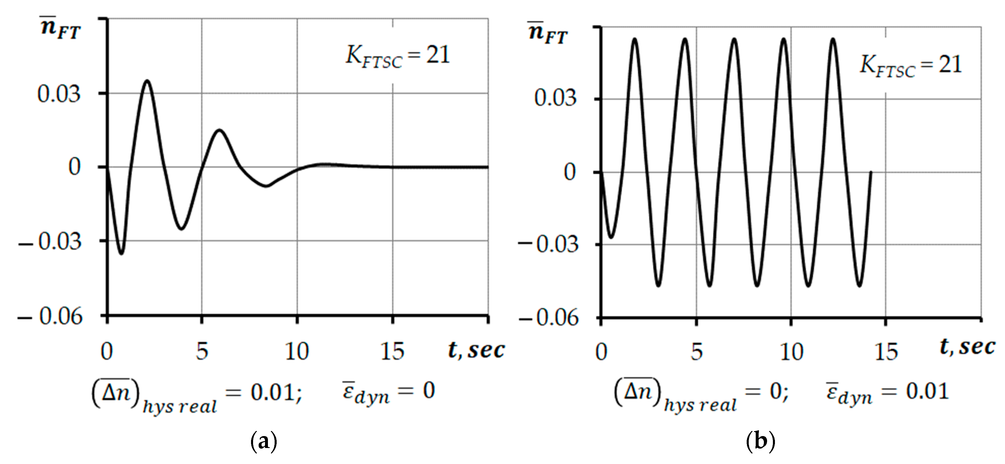
5.3. Influence of the FTSC Characteristic ‘Discontinuity’

The FTSC characteristics can consist of a discontinuity of first kind—the stepped change in fuel consumption when rotor speed of a free turbine is varied smoothly (Figure 2a). When studying the influence of the ‘discontinuity’ defect, the dynamic correction of the regulating error was taken into account and calculated by Equation (10).
Figure 8 shows the comparative analysis of the influence of the characteristic ‘discontinuity’ of FTSC operated with (FT + WB) on the response of ACS (nFT) that has average dynamic parameters in design point according to (11). In this analysis, the value of dynamic correction was set to maximum. It is seen that FTSC with a smooth characteristic has a satisfied response (Figure 8a). At the same time the ‘discontinuity’ of the FTSC characteristic leads to the development of the self-oscillations (Figure 8b).
The study of the ratio of acceptable hysteresis values and FTSC gain, ensuring the absence of self-oscillations in ACS (nFT), is of practical interest. Figure 9a presents the results of numerical study for (FT + WB). The gain of the engine has a significant effect on this ratio. So, for a ‘blunt’ engine with a gain KGG = 0.12, the absence of self-oscillations is provided by FTSC with a gain KFTSC ≤ 30 and hysteresis value within 0.006 ≤ ( Δ n ¯ ) h y s   r e a l ≤ 0.01. For engine with an average gain KGG = 0.155, only the FTSC with hysteresis ( Δ n ¯ ) h y s   r e a l ≥ 0.015 can ensure the absence of self-oscillations, which contradicts the technical specifications. There is a need to limit the gain of the FTSC. For a ‘sharp’ engine with gain KGG = 0.189, it is possible to ensure the absence of self-oscillations when testing the engine with the water brake only by limiting the FTSC gain.
It was shown that the requirements for dynamic parameters of FTSC with (FT+MR) are not so strict. Figure 9b shows the acceptable ratio of hysteresis and FTSC gain for the worst case of a ‘sharp’ engine (KGG = 0.189). It is seen that the absence of self-oscillations is provided by FTSC with gain KFTSC ≤ 30 and hysteresis value is within 0.006 ≤ ( Δ n ¯ ) h y s   r e a l ≤ 0.01.

6. Conclusions

The causes of inducing self-oscillations in the operational range of free turbine speed controller during ground tests of the TV3-117VM turboshaft with water brake installations and without automated load control systems are as follows:
  • Water brake characteristics mismatch with characteristics of the helicopter main rotor;
  • Unsatisfactory characteristics of free turbine speed controller of the NR-3 regulator-pump (discontinuity, break, mismatch of the gain factor with the requirements of technical specifications, insufficient value of the hysteresis);
  • Mismatch of the characteristics of free turbine speed controller with dynamic parameters of gas generator.
Computational studies have revealed that in order to prevent inducing and propagation of free turbine self-oscillations in testing the TV3-117VM turboshaft with water brake, it is necessary to provide a certain combination of the dynamic parameters of free turbine speed controller depending on the dynamic parameters of the gas generator (Figure 9). The significant influence of the gas generator dynamic parameters on the propagation of ACS (nFT) self-oscillations does not allow to make any judgements about the unsatisfactory characteristics of free turbine speed controller of the regulator-pump during the ground tests.
For correct testing of turboshaft engines with water brake, it is necessary to provide full emulation of the characteristics of the system (helicopter main rotor) [16,17] or make corresponding adjustments to the dynamic parameters of the controller at the time of testing. Such an adjustment may be a change in the time constant of free turbine speed controller.
When the TV3-117VM engine is used as part of a helicopter power plant, the causes of self-oscillations are poor characteristics of free turbine speed controller or a mismatch of the dynamic parameters of the controller in regulator-pump and the dynamic parameters of gas generator. A way to eliminate the self-oscillations of helicopter main rotor can be to turn off the controller with unsatisfactory characteristics by adjusting the FTSC settings accordingly—changing the driving and driven engines.

Author Contributions

Conceptualisation, V.L. and O.L.; methodology, V.L. and O.L; software, O.L and Y.M.; validation, O.L. and S.K.; formal analysis, V.L. and S.K.; investigation, O.L. and S.K.; resources, O.L. and Y.M.; data curation, O.L. and V.L.; writing—original draft preparation, O.L.; writing—review and editing, O.L., V.L., Y.M. and S.K.; supervision, V.L. and S.K.; project administration, O.L. and V.L. All authors have read and agreed to the published version of the manuscript.

Funding

This research received no external funding.

Institutional Review Board Statement

Not applicable.

Informed Consent Statement

Not applicable.

Data Availability Statement

Not applicable.

Acknowledgments

The authors are deeply grateful to Viktor Vasylovych Volosnyi (Kharkov Machine-Building Plant FED) and Vasyl Mykolaiovych Otrishko (OJSC “Motor Sich”) for their support and effective assistance in conducting experimental studies on physical objects.

Conflicts of Interest

The authors declare no conflict of interest.

Abbreviations

The following abbreviations and symbols are used in this manuscript:
FTSCFree Turbine Speed Controller
ACSAutomatic Control System
FTFree Turbine
WBWater Brake
MRMain Rotor of the Helicopter
GGGas Generator
MMVMain Metering Valve

References

  1. Ahmedzjanov, D.A. Transient operating modes of aircraft gas turbine engines. USATU Bull. Autom. Control Technol. Process. Prod. 2006, 7, 36–46. Available online: https://www.docme.su/doc/1689833/neustanovivshiesya-rezhimyraboty-aviacionnyh-gtd..pdf (accessed on 21 September 2019).
  2. Gurevich, O.S. Automatic Control Systems for Aircraft Gas Turbine Engines; TORUS PRESS: Moscow, Russia, 2010; Available online: https://search.rsl.ru/ru/record/01004961128 (accessed on 21 September 2019).
  3. Chiang Alpha, C. Elements of Dynamic Optimization; Waveland Press: Long Grove, IL, USA, 2000; 327p. [Google Scholar]
  4. Gaevsky, S.A.; Morozov, F.N.; Tikhomirov, Y.P.; Shtoda, A.V. Aviation Power Plant Automation; Shtody, A.V., Ed.; USSR: Moscow, Russia, 1980; 241p, Available online: https://ru.b-ok.global/book/3669117/2d8b3c (accessed on 21 September 2019).
  5. Volkov, V.V.; Semjonov, A.D. Dynamics of Nonlinear Mechanical Systems; Penza State Technological University: Penza, Russia, 2015. [Google Scholar]
  6. Dedesh, V.T. Stability and self-oscillations of nonlinear single-loop automatic control systems. TsAGI Sci. Notes 2010, 42, 82–92. [Google Scholar]
  7. Grushun, A.I.; Grushun, T.A. Computer analysis of self-oscillations in nonlinear automatic control systems based on the harmonic balance method. SEVNTU Bull. 2020, 146, 223–225. [Google Scholar]
  8. Tumanov, M.P.; Abdullin, S.R.; Serebrennikov, P.S. Investigation of fluctuations in control systems with a variable structure, taking into account the delay. Moscow State Forest Univ. Bull. 2020, 1, 20–30. [Google Scholar] [CrossRef]
  9. Karra, S.; Jelali, M.; Karim, M.; Horch, A. Detection and Diagnosis of Stiction in Control Loops. Advances in Industrial Control; Springer: London, UK, 2009. [Google Scholar] [CrossRef]
  10. Shoukat, C.M.A.A.; Shah, S.L.; Thornhill, N.F. Diagnosis of Process Nonlinearities and Valve Stiction. Advances in Industrial Control; Springer: London, UK, 2008. [Google Scholar]
  11. Li, C.; Shoukat, C.M.A.A.; Huang, B.; Qian, F. Frequency analysis and compensation of valve stiction in cascade control loops. J. Process Control 2014. [Google Scholar] [CrossRef]
  12. Savelyev, D.O.; Gudim, A.S.; Solovev, D. Stabilizing the Transients in the Objects and Systems Controlling the Compensation of Nonlinear ACS (Automatic Control System) Elements. In Proceedings of the 2019 International Science and Technology Conference, Vladivostok, Russia, 1–2 March 2019; pp. 575–579. [Google Scholar] [CrossRef]
  13. Gimadiev, A.G.; Bukin, V.A.; Greshhnjakov, P.I.; Utkin, A.V. Experimental study of oscillatory processes when testing a turboprop engine with hydraulic dynamometer. In Proceedings of the International Scientific and Technical Conference, Samara, Russia, 22–24 July 2016; pp. 20–21. [Google Scholar]
  14. Gruenbacher, E.; del Re, L.; Kokal, H.; Schmidt, M.; Paulweber, M. Adaptive control of engine torque with input delays. In Proceedings of the 17th World Congress the International Federation of Automatic Control, Barselona, Spain, 1 January 2008; pp. 9479–9484. [Google Scholar] [CrossRef] [Green Version]
  15. Litvjak, O.M.; Durєєv, V.O.; Maljarov, M.V.; Chigrin, V.S. Experimental study of the free turbine speed controller characteristics of NR-3 regulator-pump. In Integrated Computer Technologies in Mechanical Engineering, Proceedings of the International Scientific and Practice Conference, Kaunas, Lithuania, 9–10 May 2019; Kharkiv Aviation Institute, Zhukovsky National Aerospace University: Kharkiv, Ukraine, 2019; Volume 2, pp. 76–79. [Google Scholar]
  16. Kachanov, P.; Lytviak, O.; Derevyanko, O.; Komar, S. Development of an automated hydraulic brake control system for testing aircraft turboshaft gas turbine engines. East. Eur. J. Enterp. Technol. 2019, 6, 52–57. [Google Scholar] [CrossRef]
  17. Golovashchenko, A. Octopus or the role of the brake in the progress of turbine construction. Engine 2004, 4, 16–54. [Google Scholar]
  18. Shmyrov, V.; Loginov, V.; Fil, S.; Khaustov, A.; Bondarchuk, O.; Kalashnikov, A.; Khmelnitskiy, G. The modernization concept of aircraft An-26 and An-140 based on the use of a hybrid power system. East. Eur. J. Enterp. Technol. 2020, 1, 6–17. [Google Scholar] [CrossRef]
  19. Benini, E.; Misté, G. Performance of a Turboshaft Engine for Helicopter Applications Operating at Variable Shaft Speed; Department of Industrial Engineering, University of Padova: Padova, Italy, 2012. [Google Scholar] [CrossRef]
  20. Misté, G.; Garavello, A.; Benini, E.; Alcoy, M. New methodology for determining the optimal rotational speed of a variable RPM main rotor/Turboshaft Engine System. J. Am. Helicopter Soc. 2013, 60. [Google Scholar] [CrossRef]
  21. Yan, X.; Zhou, Q.; Jia, Y.; Chen, L. Simulation analysis of complex electromagnetic environment effect of helicopter engine. In Journal of Physics: Conference Series, Proceedings of the 2nd International Conference on Electronic Engineering and Informatics, Lanzhou, China, 17–19 July 2020; IOP Publishing: Bristol, UK, 2020; Volume 1617, Available online: https://iopscience.iop.org/article/10.1088/1742-6596/1617/1/012019/pdf (accessed on 12 February 2021).
  22. Wu, H.; Li, B.; Zhao, S.; Yang, X.; Song, H. Research on initial installed power loss of a certain type of turboshaft engine using data mining and statistical approach. Hindawi Math. Probl. Eng. 2018, 9412350. [Google Scholar] [CrossRef]
  23. Yildirim, M.T.; Kurt, B. Aircraft gas turbine engine health monitoring system by real flight data. Int. J. Aerosp. Eng. 2018, 2018, 9570873. [Google Scholar] [CrossRef] [Green Version]
  24. Yu, H.; Sun, H.; Yan, L.; Zhang, K. Study on the condition monitoring system of certain type of turboshaft engine based on flight data. In Proceedings of the First Symposium on Aviation Maintenance and Management; Springer: Berlin, Germany, 2014; Volume I, pp. 227–234. [Google Scholar] [CrossRef]
  25. Coban, K.; Colpan, C.; Karakoc, T. Application of thermodynamic laws on a military helicopter engine. Energy 2017, 140, 1427–1436. [Google Scholar] [CrossRef]
  26. Aguilar, L.; Boiko, I.; Fridman, L.; Iriarte, R. Self-Oscillations in Dynamic Systems; Birkhäuser: Basel, Switzerland, 2015. [Google Scholar]
  27. Garavello, A.; Benini, E. Preliminary Study on a Wide Speed Range Helicopter Rotor/Turboshaft System. AIAA J. Aircr. 2012, 49, 1032–1038. [Google Scholar] [CrossRef]
  28. Ozsoy, C.; Duyar, A.; Kazan, R.; Kiliç, R. Power Turbine Speed Control of The GE T700 Engine Using The Zero Steady-State Self-Tuning Regulator. In Proceedings of the International Conference on Intelligent Engineering Systems, Budapest, Hungary, 15–17 September 1997; pp. 371–378, ISBN 0-7803-3627-5. [Google Scholar]
  29. Yeo, H.; Bousman, W.; Johnson, W. Performance Analysis of a Utility Helicopter with Standard and Advanced Rotors. J. Am. Helicopter Soc. 2005, 49, 250–270. [Google Scholar] [CrossRef] [Green Version]
  30. Massaro, A.; D’Andrea, A.; Benini, E. Multiobjective-Multipoint Rotor Blade Optimization in Forward Flight Conditions Using Surrogate-Assisted Memetic Algorithms. In Proceedings of the 37th European Rotorcraft Forum, Gallarate, Italy, 13–15 September 2011. [Google Scholar]
  31. Welch, G.E. Assessment of Aerodynamic Challenges of a Variable-Speed Power Turbine for Large Civil Tilt-Rotor Application; NASA TM-2010-216758; NASA: Washington, DC, USA, 2010. Available online: https://core.ac.uk/download/pdf/10556060.pdf (accessed on 14 October 2020).
  32. Cameretti, M.; Del Pizzo, A.; Di Noia, L.; Ferrara, M.; Pascarella, C. Modeling and Investigation of a Turboprop Hybrid Electric Propulsion System. Aerospace 2018, 5, 123. [Google Scholar] [CrossRef] [Green Version]
  33. Zhao, X.; Huang, X.; Xia, T. Research on Modeling of a Micro Variable-Pitch Turboprop Engine Based on Rig Test Data. Energies 2020, 13, 1768. [Google Scholar] [CrossRef] [Green Version]
  34. Dvirnyk, Y.; Pavlenko, D.; Przysowa, R. Determination of Serviceability Limits of a Turboshaft Engine by the Criterion of Blade Natural Frequency and Stall Margin. Aerospace 2019, 6, 132. [Google Scholar] [CrossRef] [Green Version]
  35. Lu, F.; Huang, J.; Xing, Y. Fault Diagnostics for Turbo-Shaft Engine Sensors Based on a Simplified On-Board Model. Sensors 2012, 12, 11061–11076. [Google Scholar] [CrossRef] [PubMed] [Green Version]
  36. Gu, N.; Wang, X.; Lin, F. Design of Disturbance Extended State Observer (D-ESO)-Based Constrained Full State Model Predictive Controller for the Integrated Turbo-Shaft Engine/Rotor System. Energies 2019, 12, 4496. [Google Scholar] [CrossRef] [Green Version]
  37. Mihaloew, J.R.; Bab, M.G.; Ruttledge, D.G. Rotorcraft Flight—Propulsion—Control Integration: An Eclectic Design Concept; NASA TP–2815; NASA: Washington, DC, USA, 1988. Available online: https://ntrs.nasa.gov/citations/19880010091 (accessed on 12 February 2021).
  38. Sellers, J.F.; Baez Lewis, A.N.; Bobula, G.A. Amy/NASA Small Turboshaft Engine Digital Controls Research Program; NASA TM–82979; NASA: Washington, DC, USA, 1982. Available online: https://archive.org/details/DTIC_ADA122874 (accessed on 20 December 2020).
  39. Swick, R.M.; Skarvan, S.A. Investigation of Coordinated Free Turbine Engine Control Systems for Multiengine Helicopters; Technical Report; USAAVLABS: Indianahjlis, IN, USA, 1967; pp. 67–73. Available online: https://apps.dtic.mil/dtic/tr/fulltext/u2/666796.pdf (accessed on 21 September 2019).
Figure 1. The throttle characteristics of the engine.
Aerospace 08 00114 g001
Figure 2. Static characteristics of FTSC with defects. (a) ‘discontinuity’; (b) ‘break’.
Aerospace 08 00114 g002
Figure 3. Movement of the operating point.
Aerospace 08 00114 g003
Figure 4. Structural-dynamic scheme of ACS (nFT) with (FT + WB) system.
Aerospace 08 00114 g004
Figure 5. Influence of KFTSC on ACS (nFT) response with (FT + WB). (a) KFTSC = 17; (b) KFTSC = 28.
Aerospace 08 00114 g005
Figure 6. Influence of KGG on ACS (nFT) response with (FT + WB). (a) KGG = 0.12; (b) KGG = 0.189.
Aerospace 08 00114 g006
Figure 7. The acceptable range of KFTSC. (a) for (FT + WB) with different level of empirical hysteresis; (b) for both (FT + WB) and (FT + MR) with zero hysteresis.
Aerospace 08 00114 g007
Figure 8. Influence of the characteristic ‘discontinuity’ of FTSC operated with (FT + WB) on the response of ACS (nFT). (a) smooth characteristic of FTSC; (b) FTSC characteristic with ‘discontinuity’.
Aerospace 08 00114 g008
Figure 9. Acceptable values of hysteresis and FTSC gain for ACS (nFT) with different plants: (a) with (FT + WB); (b) with (FT + MR).
Aerospace 08 00114 g009
Publisher’s Note: MDPI stays neutral with regard to jurisdictional claims in published maps and institutional affiliations.

