1. Introduction
The amount of fossil fuels is limited in nature. In addition, it has harmful effects such as air pollution and greenhouse effects. For these reasons, it is necessary to reduce the use of fossil fuels in transportation, as in other engineering applications. To meet this requirement, studies are carried out on hybrid systems in both academic and commercial fields [
1]. Many application examples of these hybrid systems are available in vehicles such as ferries, trains, airplanes, unmanned aerial vehicles, and buses [
2,
3,
4]. The hybrid systems can be constituted between internal combustion engines and energy storage components or between energy storage components only. Common energy storage components are batteries, supercapacitors, and fuel cell stack. In addition, solar cells, piezoelectric materials, and flywheels can be part of a hybrid system [
5]. By constituting hybrid systems, the superior features of each component can be used. Among the battery, fuel cell, and supercapacitor, the fuel cell has the highest energy density, while the supercapacitor has the highest power density. Fuel cells have drawbacks such as long start-up time, delayed response, and weak power performance. Therefore, in general, battery/supercapacitor or more complicated hybrid energy storage units are preferred in hybrid vehicles. Batteries or fuel cells are the strongest candidates in terms of meeting the energy demand alone as the battery and fuel cell technology develop. Polymer electrolyte membrane (PEM) fuel cell (FC), direct methanol (DM) FC, and solid oxide (SO) FC can be used for propulsion systems [
6]. However, PEMFC is more suitable than DMFC and SOFC for aviation systems due to its low weight, low operating temperature, and response speed characteristics [
7,
8]. As another energy source, solar cells can be added to the system. However, it requires wide surface areas and their efficiency is low [
9]. Besides, supercapacitors are used as auxiliary sources in the system rather than meeting the energy requirement alone. Their power density is much higher than other energy sources. They can supply the instantaneous high power demand and are used for this purpose in systems. In the hybrid system used for unmanned aerial vehicles (UAVs), it has been observed that the supercapacitor increases the total system efficiency [
7,
10,
11]. Similar to supercapacitors, flywheels are used to meet the instant high power demand [
12]. Although flywheels can be used in land and marine applications, they are not quite preferred in aviation applications because of airborne risks of rotating machinery and weight considerations. In addition, the gyroscopic effect of the flywheel negatively affects the maneuverability of the aircraft. In the hybrid systems, piezoelectric materials can be used as energy sources, but they can only generate very low amounts of energy. Their energy production can only meet the power demand of small electrical elements. For the above-mentioned reasons, battery, supercapacitor and fuel cell stack are generally used as complementary to each other in the hybrid systems applied in vehicles.
The hybrid systems need energy management to increase total system efficiency, reduce fuel consumption, and maintain the performance and lifetime of each component [
13]. There are many studies in the literature on energy management of hybrid systems formed by internal combustion engines and electric motors [
14,
15]. However, there is limited study on the energy management of fully electrical systems in aircraft. In these studies, the energy management has generally been conducted with rule-based approaches. In the energy management, the ability of meta-heuristic algorithms to converge the global optimum without getting stuck at local optimum can be useful. In addition, meta-heuristic algorithms have been shown to give satisfying results in solving complex nonlinear problems with multiple inputs and multiple outputs [
16,
17]. In the literature, some rule-based energy management techniques were applied to the hybrid system used this study. In addition, strategies such as optimization based equivalent consumption minimization (ECMS) and external energy maximization (EEMS) were implemented to reduce hydrogen consumption [
18]. Although the computational burden of rule-based energy management techniques are low, they cannot guarantee global optimum. An energy management system is expected to provide results close to global optimum, as well as to be implemented in real-time. In this context, the meta-heuristic algorithms can ensure better results than rule-based approaches. In this study, this gap in the literature was investigated by using meta-heuristics algorithms. In this respect, a comparison study of meta-heuristic algorithms for energy management of triple hybrid system is presented in this paper. The equivalent consumption minimization strategy (ECMS) and classical proportional integral (PI) control strategy were chosen as benchmarks and meta-heuristic algorithms were compared with these benchmarking strategies. In addition, the computational times of these were obtained and compared for a triple hybrid system consisting of fuel cell, battery, and supercapacitor.
The state of charge (SOC) of the batteries is generally not desired to fall below 20% during operation. Fuel cells should not be subjected to sudden high loads. Furthermore, in the hybrid systems, it is an important issue to distribute the stored energy among these resources under certain limits according to the required power demand. All of these operational restrictions should be controlled in the hybrid systems. In this sense, there are two methods for energy management, active or passive. In active method, energy management is performed through DC/DC converters, while passive method is based on direct voltage matching, not using DC/DC converters. The passive systems have a simpler structure, but it has been observed that active energy management systems are more efficient [
19,
20]. The active energy management is generally conducted with methods that can be examined under two general groups: rule-based and optimization-based strategies. The rule-based energy management strategies aim to increase the performance of the system according to a predetermined set of rules, whereas optimization-based approaches aim to optimize the system according to a created objective function. The rule-based strategies (e.g., state machine control and proportional-integral (PI) control) are suitable for real-time implementation due to their simple structure, but their efficiency is low. Although the efficiency of optimization-based methods is high, the computational burden is also high. This problem can be solved using intelligent control techniques and meta-heuristic algorithms for real-time applications. That is why many studies utilizing meta-heuristic algorithms are used in real-time energy management of electric vehicles (e.g., [
21,
22,
23]). Two of the biggest problems encountered in energy management are: (1) keeping the calculation time short (to be suitable for real-time applications): and (2) reflecting the external dynamics of the problem in the model [
24]. Researchers have conducted many studies to solve these two problems (e.g., [
25,
26]). In contrast to traditional optimization methods, meta-heuristic methods are suitable for achieving shorter calculations time [
1,
27]. Some meta-heuristic algorithms have been applied to the hybrid system consisting of battery, supercapacitor, and fuel cell stack, as used in this study [
26,
28,
29,
30,
31]. The novelty of this study is the first application of the ant lion optimizer, sine cosine algorithm, and moth-flame optimization algorithm on a triple hybrid energy provider system. In addition, many meta-heuristic algorithms were compared in terms of computational time and hydrogen consumption. According to these comparison criteria, the sine cosine algorithm gave best result. Besides, it was found to provide lower hydrogen consumption than studies in the literature. Although there are many studies on the use of meta-heuristic algorithms in energy management of other electric vehicles, there are very few studies in aerial vehicles. In this regard, the current study has considerable importance.
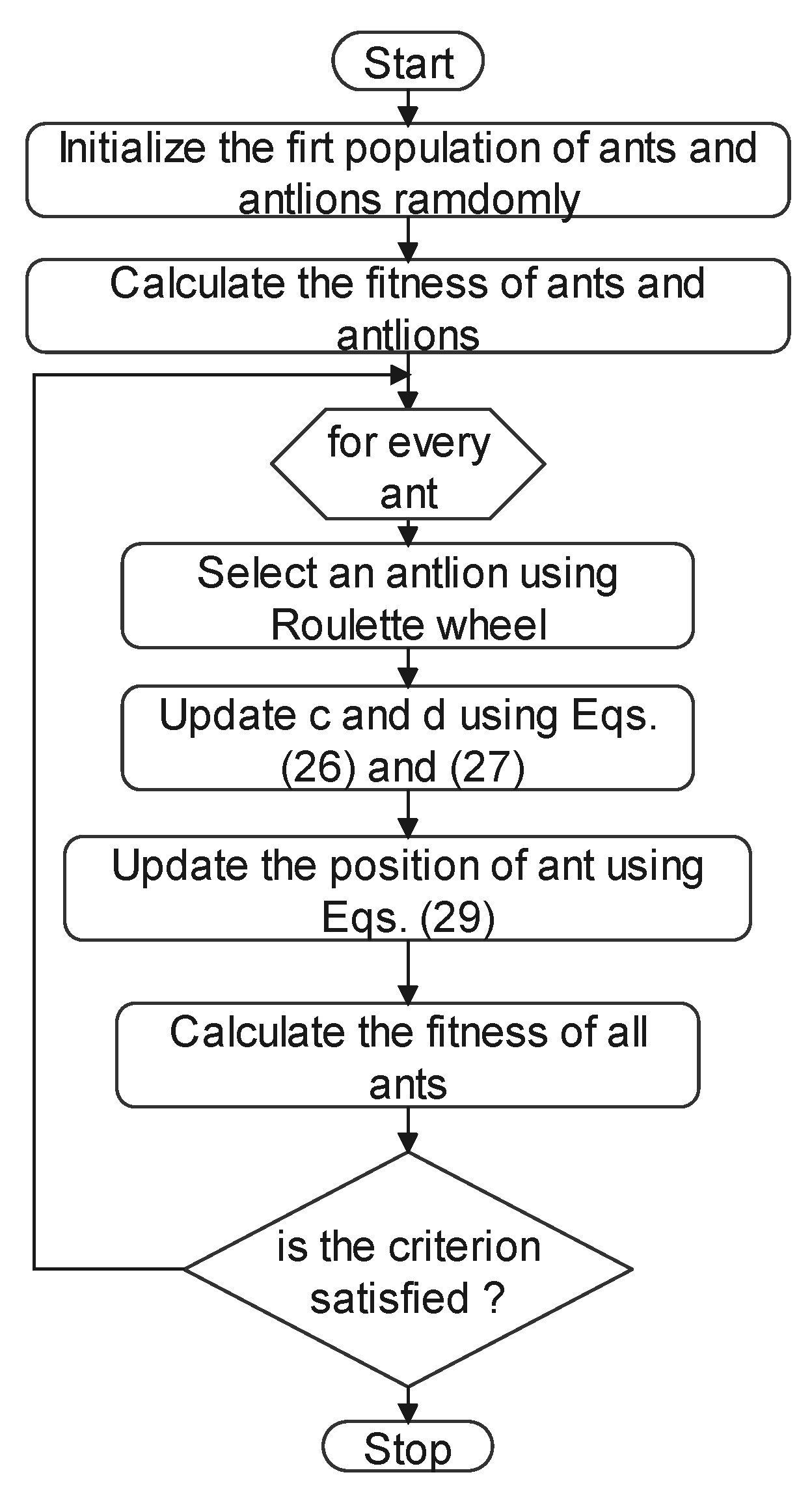
Based on the above reasoning, the current paper presents energy management and optimization of the triple hybrid system consisting of battery, supercapacitor, and fuel cell stack, using ant lion optimizer (ALO) [
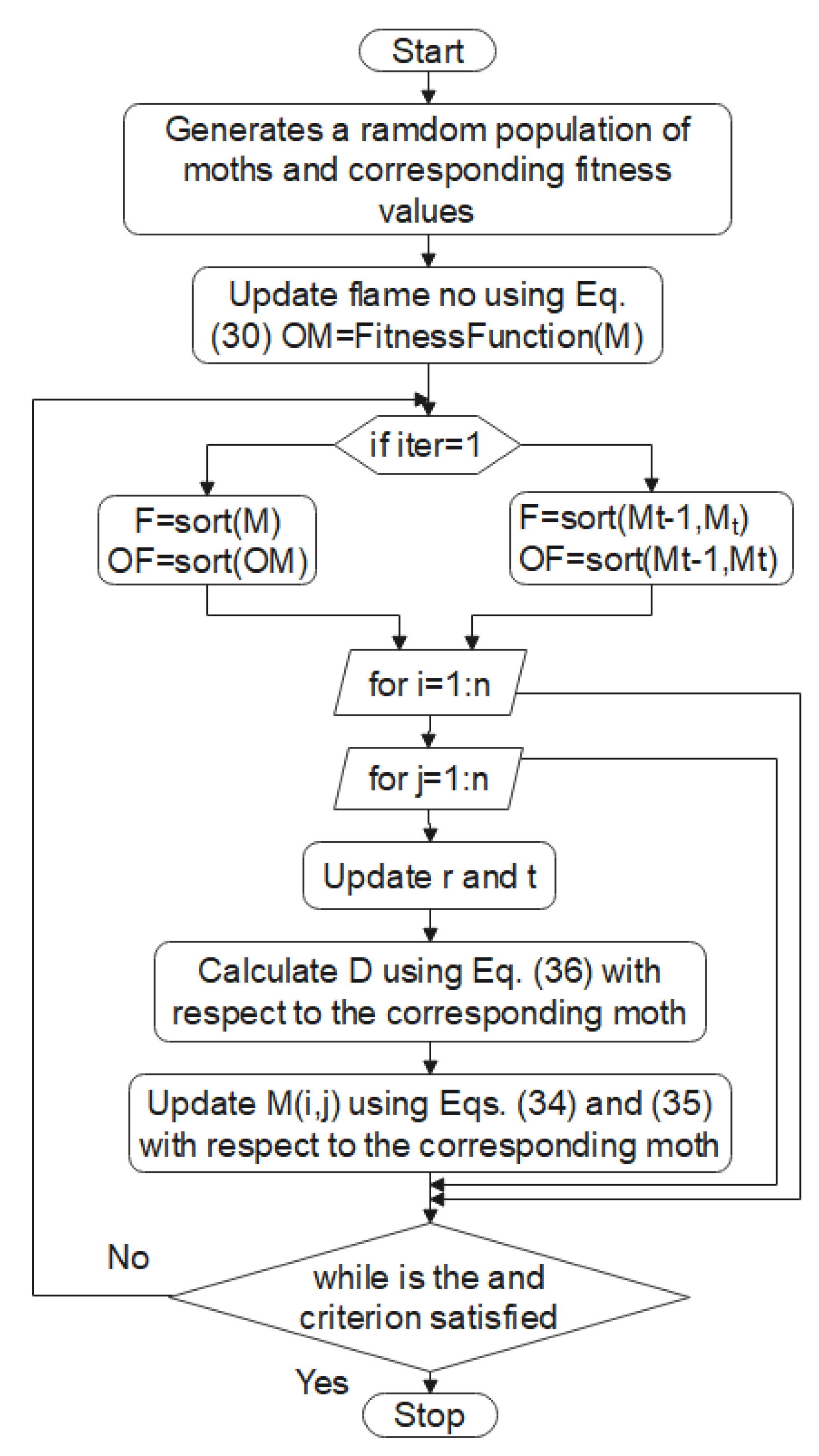
32], moth-flame optimization (MFO) [
33], dragonfly algorithm (DA) [
34], multi-verse optimizer (MVO) [
35], particle swarm optimization (PSO) [
36], whale optimization algorithm (WOA) [
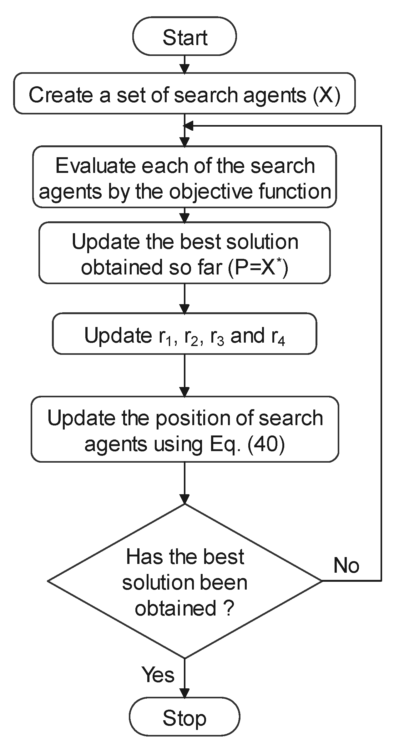
37], and sine cosine algorithm (SCA) [
38] algorithms. In the system used in this study, the battery and fuel cell stack are connected to the system through DC/DC converters, and the supercapacitor is directly connected to the DC bus. For this reason, active energy management was applied to the hybrid system. Studies were conducted in Matlab/Simulink (R2020b) environment. For the integration of the energy management system into the Matlab/Simulink model, the first Type S-Function was used. The aim of the system was to ensure the distribution of energy between sources by minimizing hydrogen consumption. After the determination of the most suitable optimization algorithm, its effect on the model was examined using the same algorithm.
Section 2 presents the information about the components of the systems in the model and the modeling process.
Section 3 explains the meta-heuristic algorithms used for optimization.
Section 4 gives the results and determines the most suitable algorithm in terms of hydrogen consumption.
Section 5 presents the results together with the discussion. Lastly, the future research direction concludes the study.
2. Structure of the Hybrid Energy Supply System
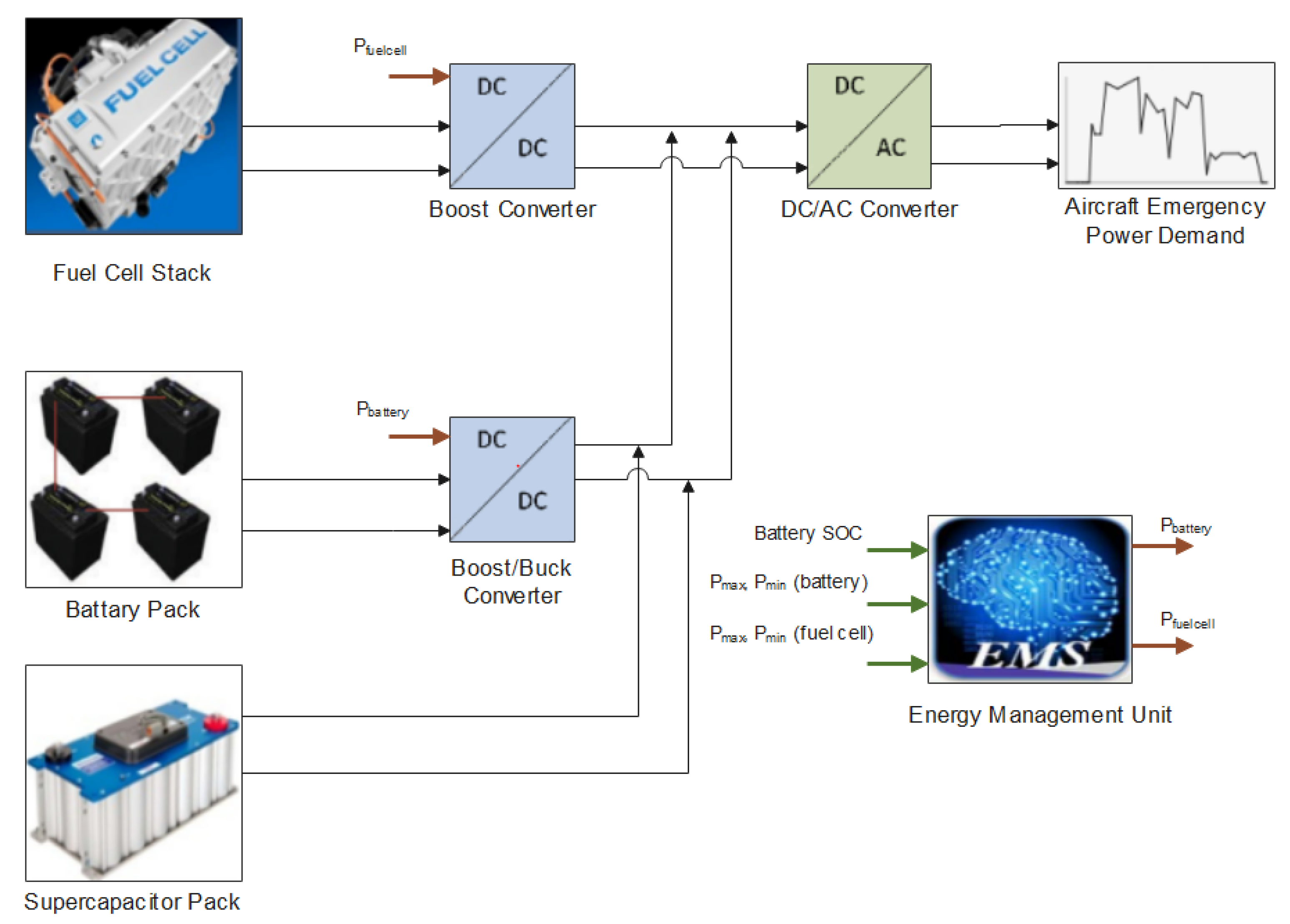
The hybrid system, in which power optimization is applied, consists of a 40 Ah lithium-ion battery, pack of 108 serially connected supercapacitors with 15.6 Farad over all capacity, and PEM type fuel cell stack. The specifications of the energy components used in the hybrid system are given in
Table 1. The battery and fuel cells were connected to the system through DC/DC converters. The structure of the system is shown
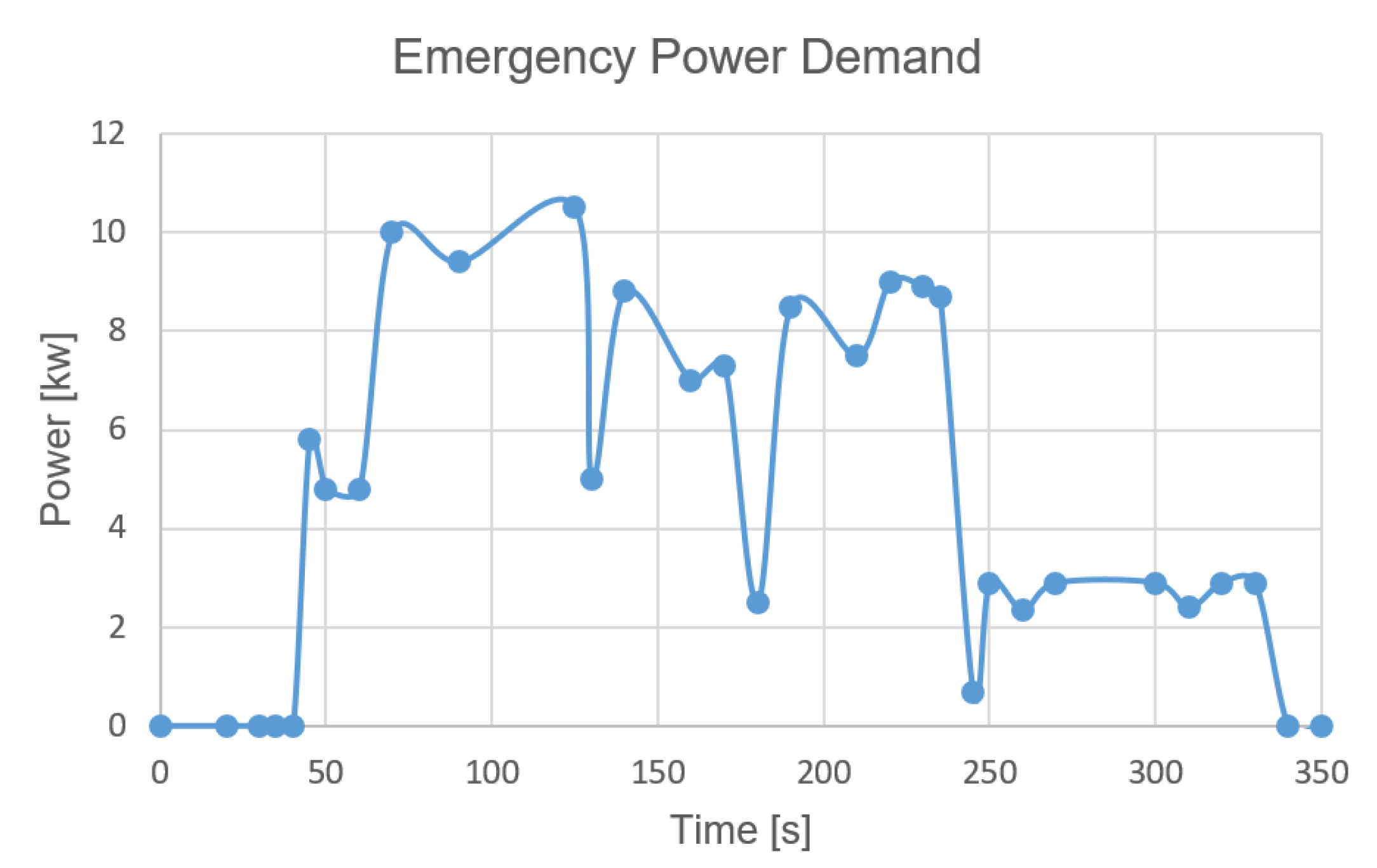
Figure 1. The supercapacitor is directly connected to the system. The demand power to the system is an input value, and, in this system, the demand power is required to be met with the least hydrogen consumption. To minimize hydrogen consumption, it is aimed to provide as much of the demanded power from the battery and the supercapacitor within the usage limits as possible. The input values of the energy management unit are battery SOC value and system voltage. The output values of the energy management unit are the current drawn from the battery and fuel cell stack. The energy management system unit decides how much current will be drawn from the battery and fuel cell stack. The current drawn from the battery and fuel cell stack are controlled by DC/DC converters. The main purpose of optimization in the system is to meet the demanded power with the least hydrogen consumption. The power demanded in the simulation is given as input and it is desired to provide this demanded power in the most optimized ways. The power demand is shown in
Figure 2 [
18]. In the literature, there are studies that use this power demand to manage energy in this hybrid system (e.g., [
26,
28,
29,
30]). The purpose of the system is not to meet the total power demand for an aircraft. In other words, this hybrid system is not used as the main energy source in aircraft. The purpose of the hybrid system, whose simulation studies were carried out, is to meet the emergency power demand in an aircraft. In this context, it is a system that will be used as an auxiliary energy source in an aircraft. The average and peak value of the aircraft emergency load demand is 7.5 and 10.5 kW. The DC bus voltage of the system was set to 270 V (usually as in an aircraft) [
18]. To meet these requirements, the properties of the fuel cell, battery, and supercapacitor were determined according to demand power. The battery SOC value was chosen the same as in the literature for comparison [
29]. The hybrid system architecture in
Figure 1 was selected by comparing nine different topologies. According to the comparison study by S. Njoya Motapon [
31], the system presented in
Figure 1 is the most suitable hybrid system in terms of weight, efficiency, power controllability, and cost. Efficiency values in the model of DC/DC converters are given in
Table 2. These efficiency values were assumed to vary linearly between 10% and 100% load conditions.
The objective function used in optimization is Equation (
1). Equations (2)–(4) are the constraints of the optimization problem [
18]. According to these constraints, it is aimed to maximize the objective function. The battery state of charge (SOC) control is provided with Equation (
2). Equation (
3) restricts the minimum and maximum values of battery power. Equation (
4) restricts the system voltage to the minimum and maximum values. By maximizing the J function, the battery and supercapacitor will give the most power they can give within the allowed limits. Thus, hydrogen consumption in the fuel cell will be reduced during the simulation.
where
,
,
,
,
,
,
,
,
, and
J represent power drawn from the battery (W), supercapacitor capacitance (F), minimum value of DC voltage for bus (V), maximum value of DC voltage for bus (V), minimum battery state of charge (%), battery instant state of charge (%), time interval (s), battery maximum power (W), battery minimum power (W), and objective function, respectively.
2.1. Battery Model
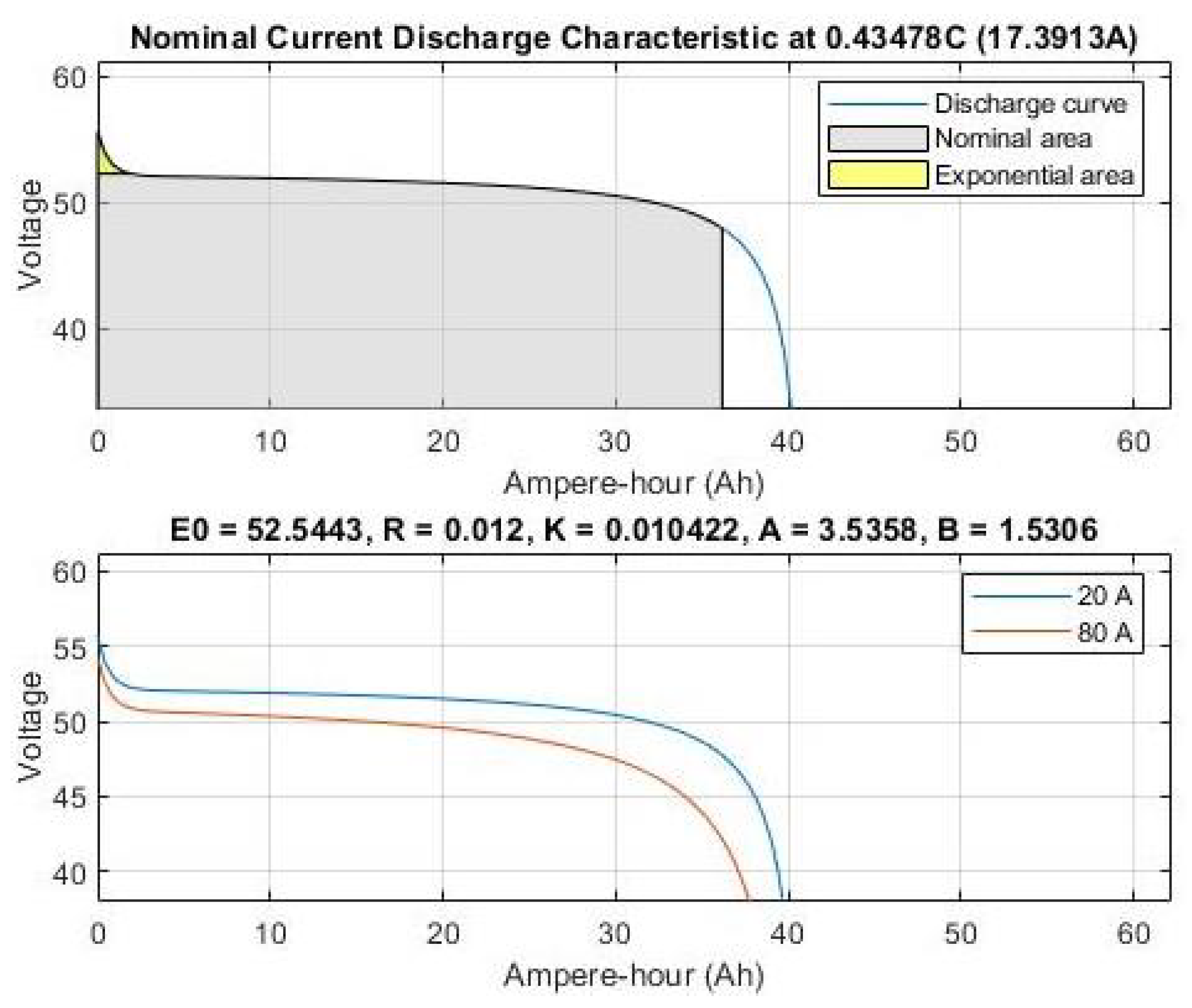
A Lithium-ion type battery with a capacity of 40 Ah was modeled in the system used in this study. The battery model used is in the Matlab/Simulink/Simscape library. Equation (
5) represents the discharge state of the battery and Equation (
6) represents the state of charge [
39]. The discharge curve of the battery is shown in
Figure 3 and its features are given in
Table 3.
where
,
,
i,
,
R,
K,
,
Q,
B, and
A represent battery voltage (V), battery constant voltage (V), battery current (A), filtered battery current (A), internal resistance (Ohm), polarization constant (V/Ah), actual battery current (A), maximum battery capacity (Ah), exponential capacity (A/h), and exponential voltage (V), respectively.
2.2. Supercapacitor Model
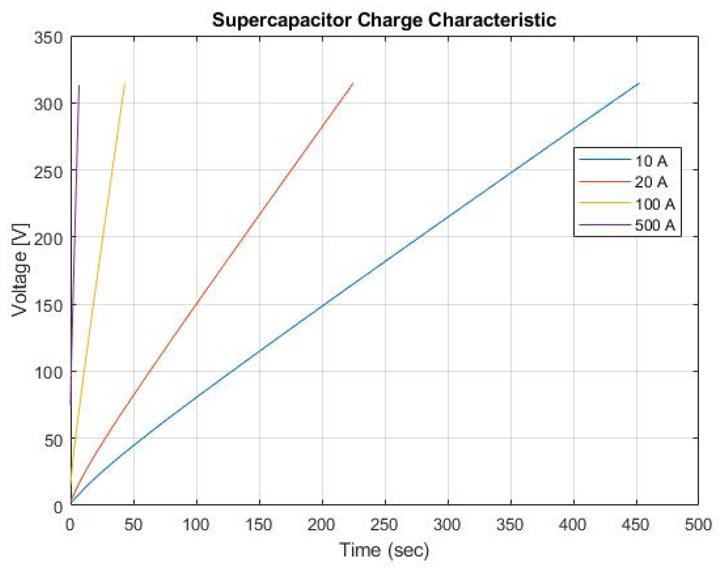
In the study, the model existing in Matlab/Simulink/Simscape library was used for supercapacitor model. The model was established according to Equations (7)–(9) [
39]. The charge curve of the supercapacitor is shown in
Figure 4. The properties of the supercapacitor are shown in
Table 4.
where
C,
,
,
, ∈,
,
,
d,
c,
, and
T represent supercapacitor capacitance (F), Helmholtz capacitance (F), Gouy-Chapman capacitance (F), number of electrode layers, permeability of electronic material (F/m), permeability of free volume (F/m), free surface area between electrode and electrolyte (m
), Helmholtz sheet length (m), molar concentration (mol/m
), the electric charge of the cell (C), and temperature (K), respectively.
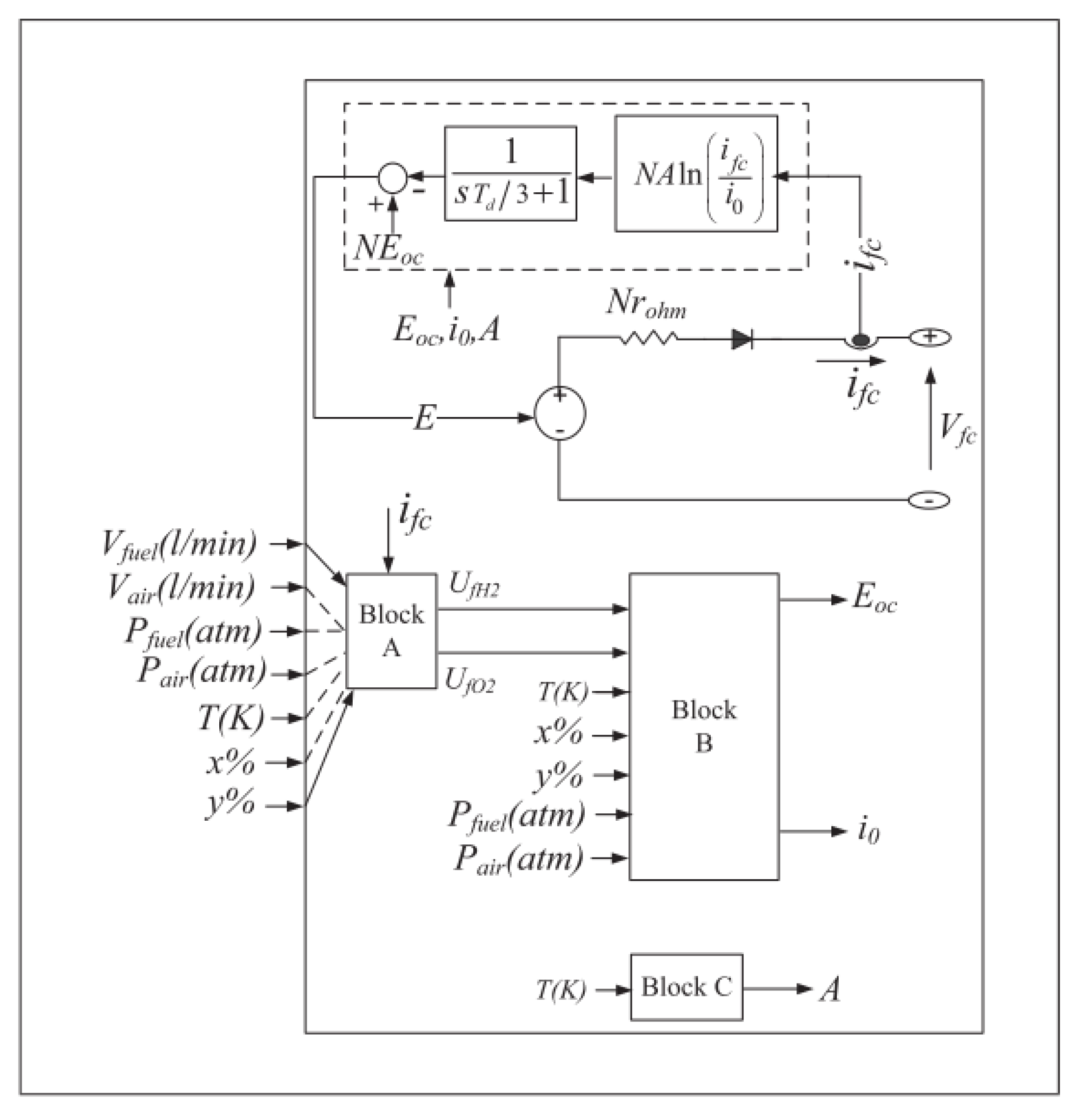
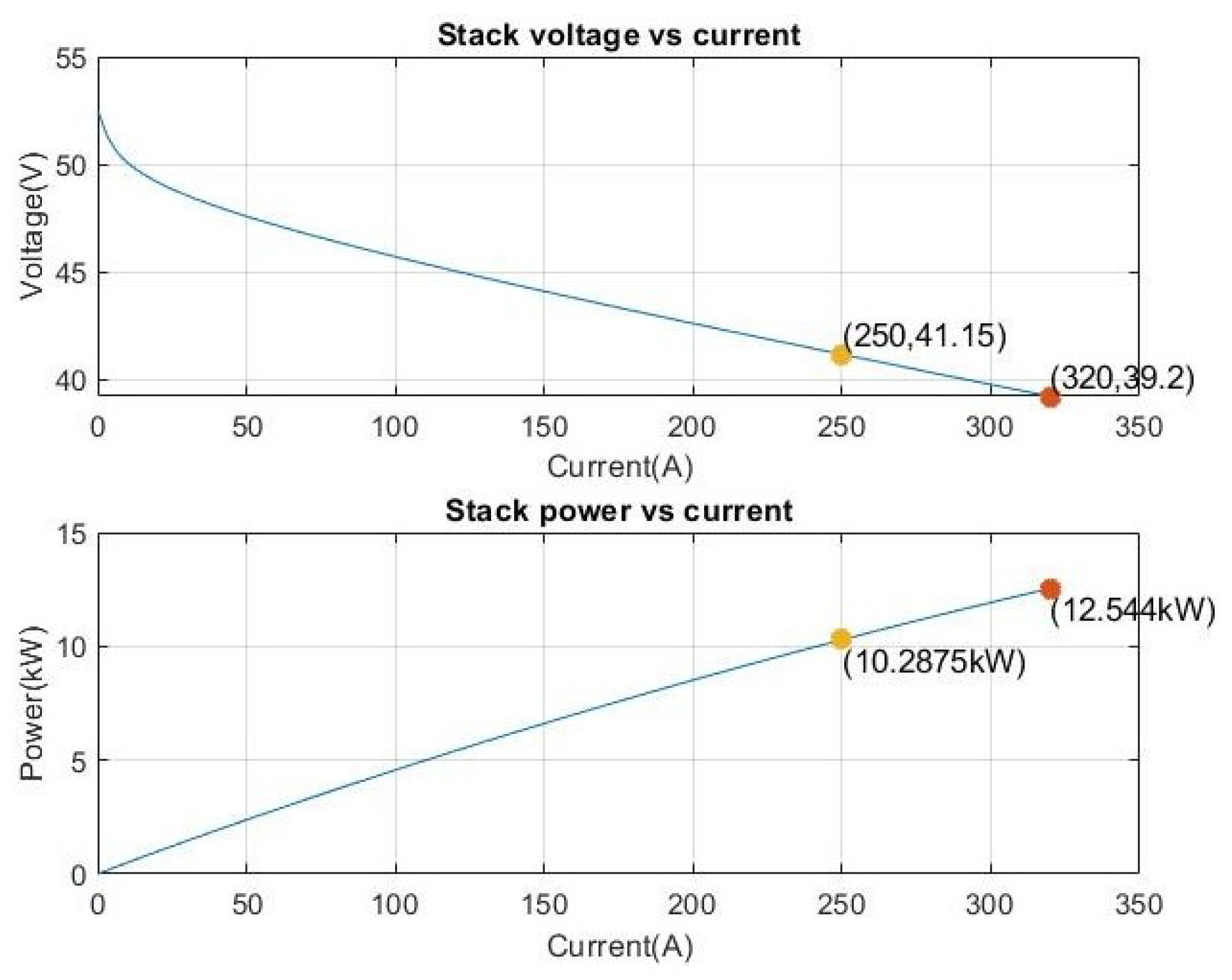
2.3. Fuel Cell Model
The model of the fuel cell stack used in the study is shown in
Figure 5. This model is the improved version of the model designed in [
40,
41]. The performance curve of the fuel cell is shown in
Figure 6. The characteristics of the fuel cell model used in Matlab/Simulink/Simscape are given in
Table 5. In
Figure 5, Block A represents Equations (10) and (11) [
18]. These equations show the uses of hydrogen and oxygen. Block B represents Equations (12)–(16) [
18]. Equation (
14) gives the thermodynamic voltage. Equations (12) and (13) show the partial pressures of oxygen and hydrogen. Equation (
15) gives cell open circuit voltage. In the case of lack of oxygen inside the cell, Nernst voltage is given by Equation (
16). Block C represents Equation (
17) [
18]. For all equations for the fuel cell model, the study of Souleman Njoya Motapon [
18] was used.
where
,
,
F,
R,
,
,
,
T,
,
,
x, and
y represent hydrogen consumption, oxygen consumption, faraday constant (A s/mol), ideal gas constant (J/mol K), cell current (A), air flow (l/min), fuel flow (l/min), operating temperature (K), fuel pressure (atm), air pressure (atm), percentage of hydrogen in fuel, and percentage of oxygen in air, respectively.
where
T,
,
,
,
,
,
,
, ∝,
A, and
represent operating temperature (K), hydrogen partial pressure (atm), oxygen partial pressure (atm), voltage constant, open loop voltage (V), voltage constant, thermodynamic voltage, voltage undershoot constant, charge transfer coefficient, Tafel slope, and nominal oxygen usage (%), respectively.
4. Simulation Results and Discussion
Energy management and optimization has been applied to the system shown in
Figure 1, which consists of battery, supercapacitor, and fuel cell stack. This system is designed to meet the energy requirement in emergency landing situations. This system consists of a 40 Ah lithium-ion battery, a PEM fuel cell with a rated power of 10 kW, and 108 supercapacitors with a 16.6 F capacitance. The DC/DC converters were used to apply the signals output from the energy management unit. A boost converter with 45 A load capacity was used for the fuel cell stack. A boost converter with a load current of 18 A and a buck converter with a load current of 20 A were used for the battery. No converter is used for the supercapacitor and is directly connected to the system bus. The input variables of the energy management unit are battery SOC and load demand. The output variables of the energy management unit are battery and fuel cell current values. A DC/AC converter with an output frequency of 400 Hz was used in the system to convert direct current to alternating current.
Simulation studies were conducted in Matlab/Simulink. Additionally, Simulink/Simscape (R2020b) library was used for the battery, supercapacitor, and fuel cell models. Optimization algorithms were implemented with the S-function block in Matlab/Simulink [
6]. The purpose of optimization study is to provide energy distribution between sources by minimizing hydrogen consumption. In addition to minimizing hydrogen consumption, battery and supercapacitor states of charge control were performed. In simulation studies, demand power is assumed to be known beforehand and applied as external input (
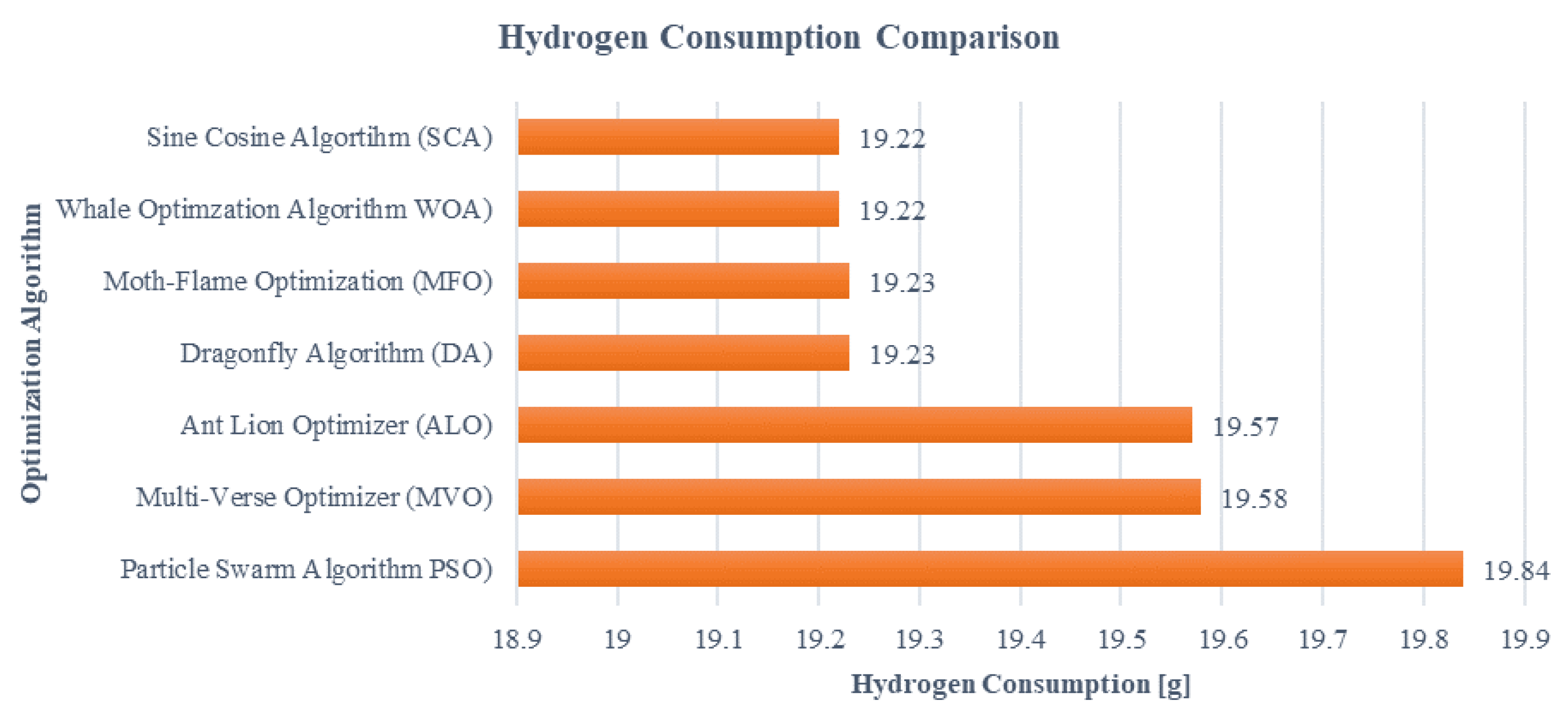
Figure 2). The purpose of the simulation study is to provide this demand power by consuming the least hydrogen. For this purpose, the optimization methods of sine cosine algorithm (SCA), moth-flame optimization algorithm (MFO), multi-verse optimizer algorithm (MVO), dragonfly algorithm (DA), ant lion optimizer (ALO), particle swarm optimization algorithm (PSO), and whale optimization algorithm (WOA) were applied to the hybrid system. The SCA reached the best result in terms of hydrogen consumption and computational times. The hydrogen consumption of this algorithm was 19.2250 g at the end of the simulation. The results obtained in terms of hydrogen consumption are given in
Figure 10. According to the results, although nearly similar results were obtained with other meta-heuristic algorithms, there are serious differences in calculation times. Simulation studies were conducted in discrete type and sample time 0.0001 s. Calculation times for these settings are given in
Table 6. The sine cosine algorithm provided the best result in terms of the calculation time. This result is important in determining which meta-heuristic algorithm to choose for energy management.
Many optimization methods have been applied to this hybrid system in the literature (e.g., rule-based and optimization-based management methods [
18,
29]). State machine control strategy, classical proportional-integral (PI) control strategy, frequency control strategy, equivalent consumption minimization strategy (ECMS), and external energy maximization strategy (EEMS) methods were applied as non-meta-heuristic methods. However, meta-heuristic algorithms have reached a better result in terms of hydrogen consumption compared to these methods [
43]. The meta-heuristic algorithms applied in the literature are shown in
Table 7. It is seen that the optimization methods applied in
Table 7 provide similar results in terms of hydrogen consumption. As shown in
Table 7, hydrogen consumption for the particle swarm optimization algorithm in the literature was found to be 25.43 g at the end of the simulation. In this study, it was found as 19.84 g for the same algorithm. In this study, no separate code was written for the particle swarm optimization algorithm, but the particleswarm solver in the Matlab/Simulink R2020b (academic license) library was used [
39]. The difference may be mainly due to this situation, as well as attributes such as population number, number of iterations, etc. Among the methods used in the literature, the lowest result was obtained with the Coyote algorithm with 19.37 g [
26]. In this study, it was seen that the SCA provided the lowest result with 19.2250 g. It is seen that the simulations performed in this study give results very close to the ones in the literature.
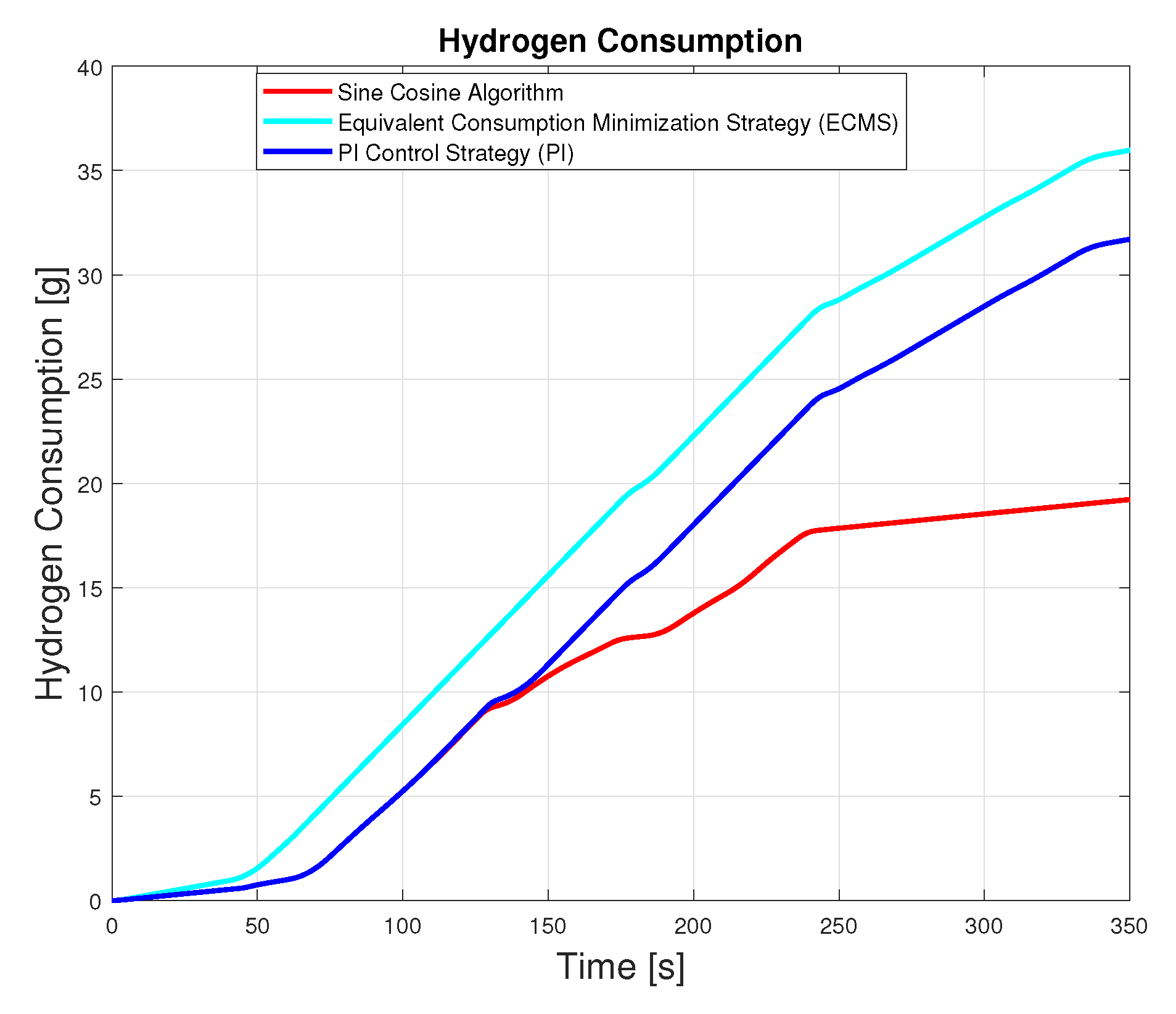
Hydrogen change during simulation for different optimization algorithms is shown in
Figure 11. This figure shows that sine cosine algorithm provide superiority over ECMS and PI control.
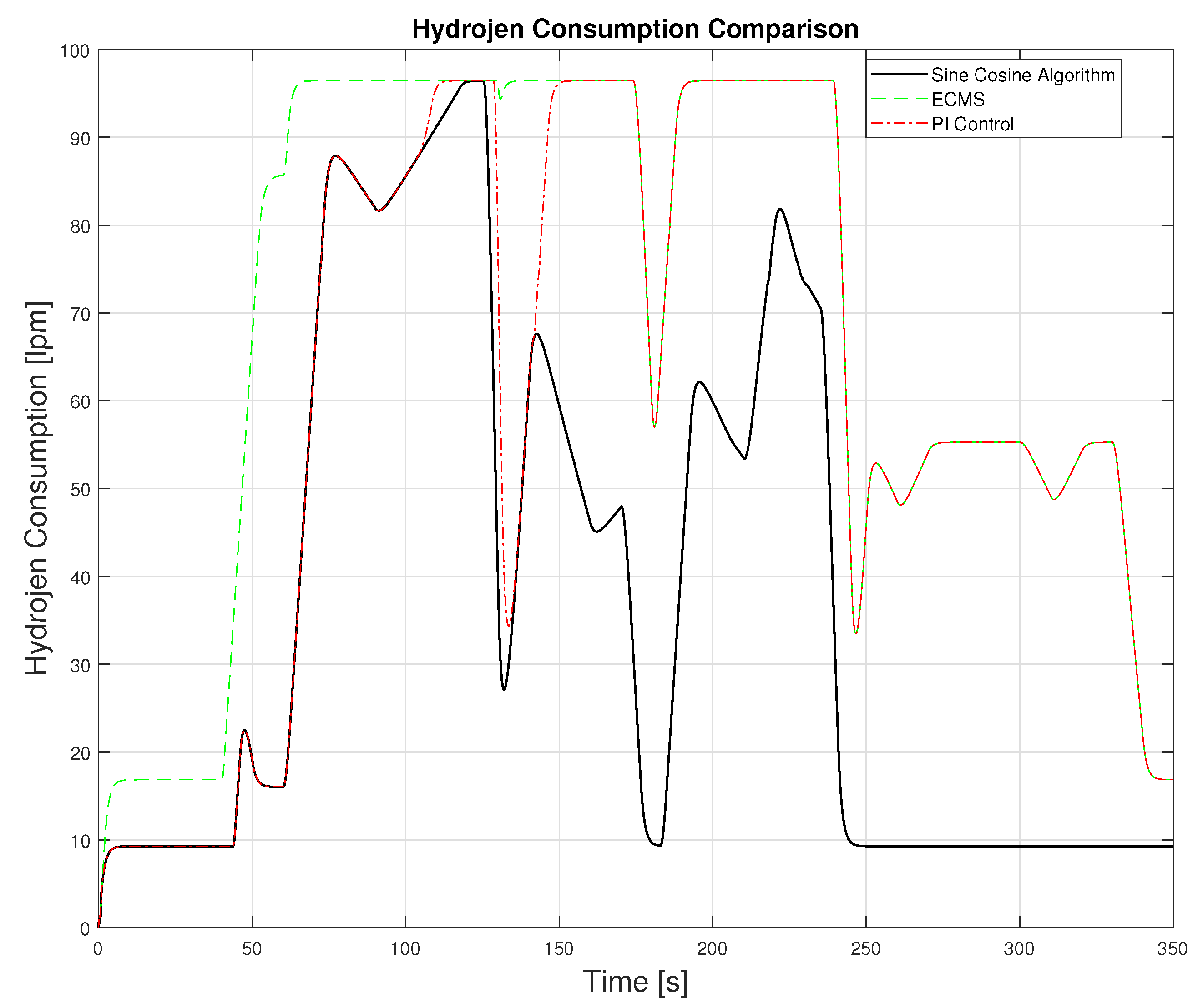
The current study contributes to the literature by applying ant lion optimizer algorithm, moth-flame optimization algorithm, and sine cosine algorithm for the first time in a hybrid energy storage system. Hence, this study introduces three novel optimization algorithms for hybrid system development holding a great potential for fresh studies. The applied optimization algorithms outperformed the traditional ECMS and PI control method in terms of hydrogen consumption. The variation of the optimization methods applied during the simulation is shown in
Figure 12.
Since the sine cosine algorithm provides the best result among the optimization methods applied,
Figure 13,
Figure 14,
Figure 15,
Figure 16,
Figure 17 and
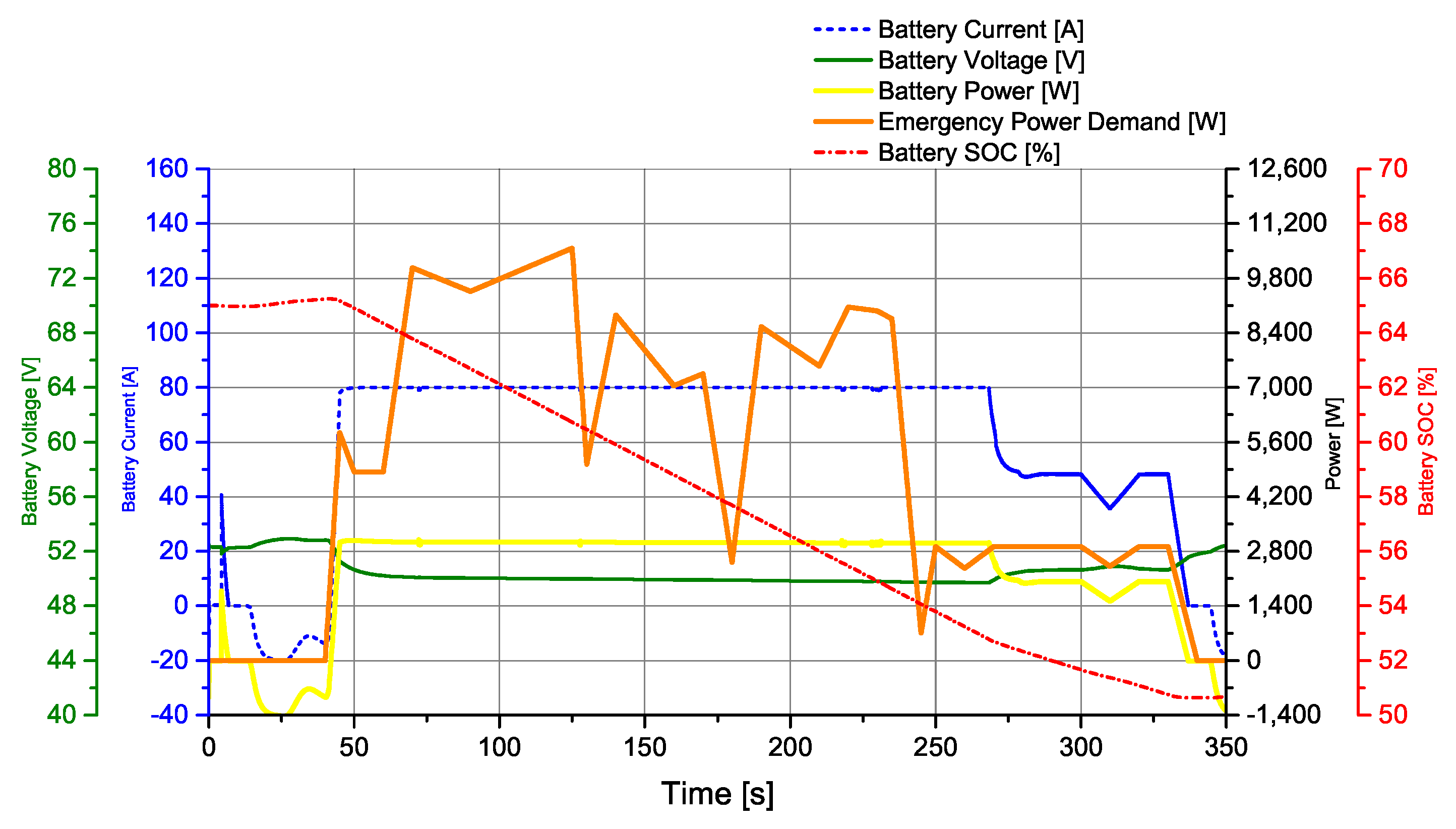
Figure 18 related to this algorithm are given. The current, voltage, and SOC changes of the battery during the simulation are shown in
Figure 13. The battery SOC status was set to the lower and upper limits of 65% and 50%, respectively. It was observed that the power drawn from the battery remained between −1400 and 3000 W. The battery voltage remained within 49–53 V. Battery current reached the highest level of 80 A.
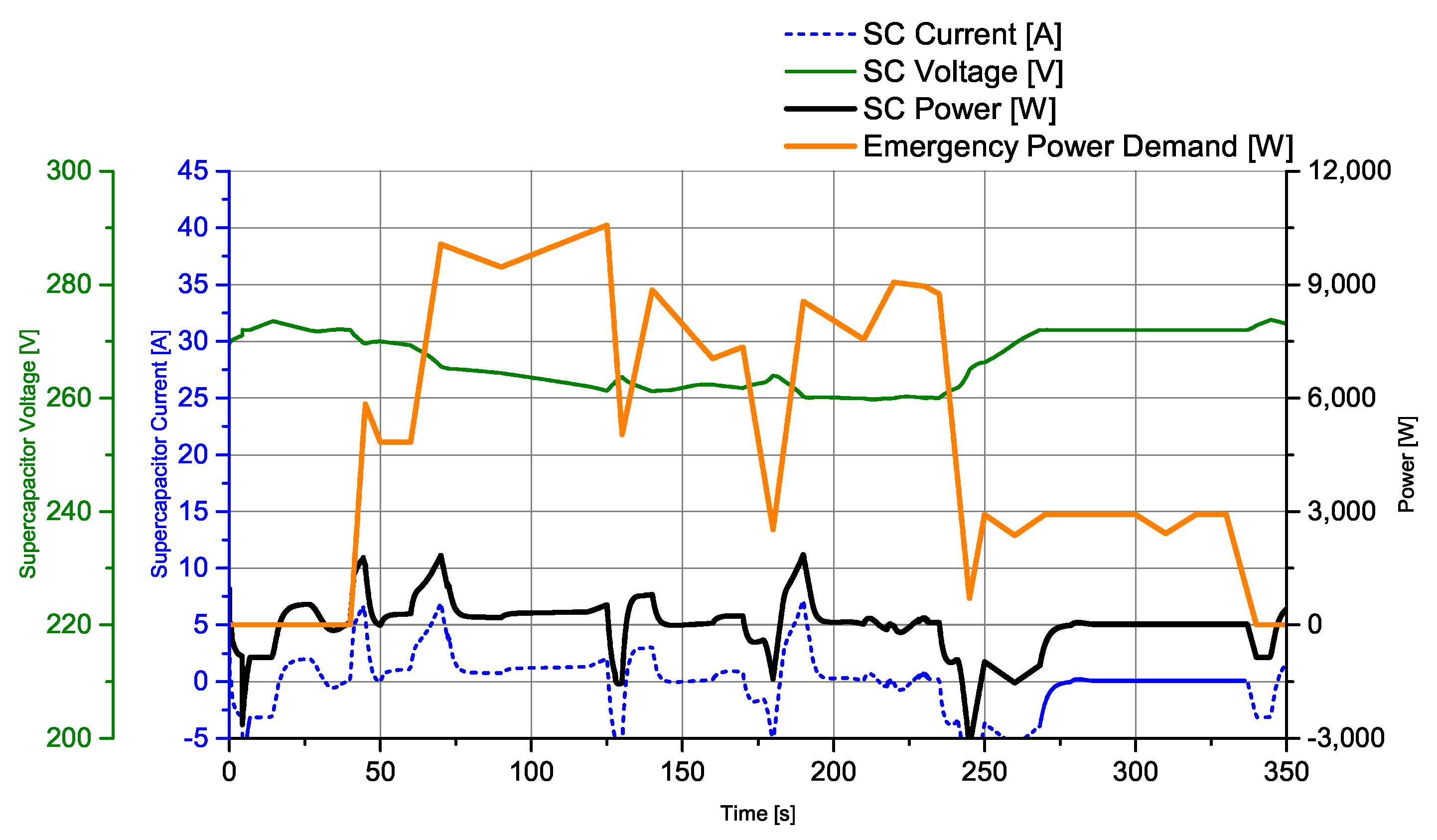
The current and voltage variation of the supercapacitor for the sine cosine algorithm during the simulation are shown in
Figure 14. The supercapacitor was directly connected to the system bus. No DC/DC converter was used for supercapacitor. The supercapacitor operating voltage was around 270 V, which was the operating voltage of the system. During simulation, it changed within 255–275 V.
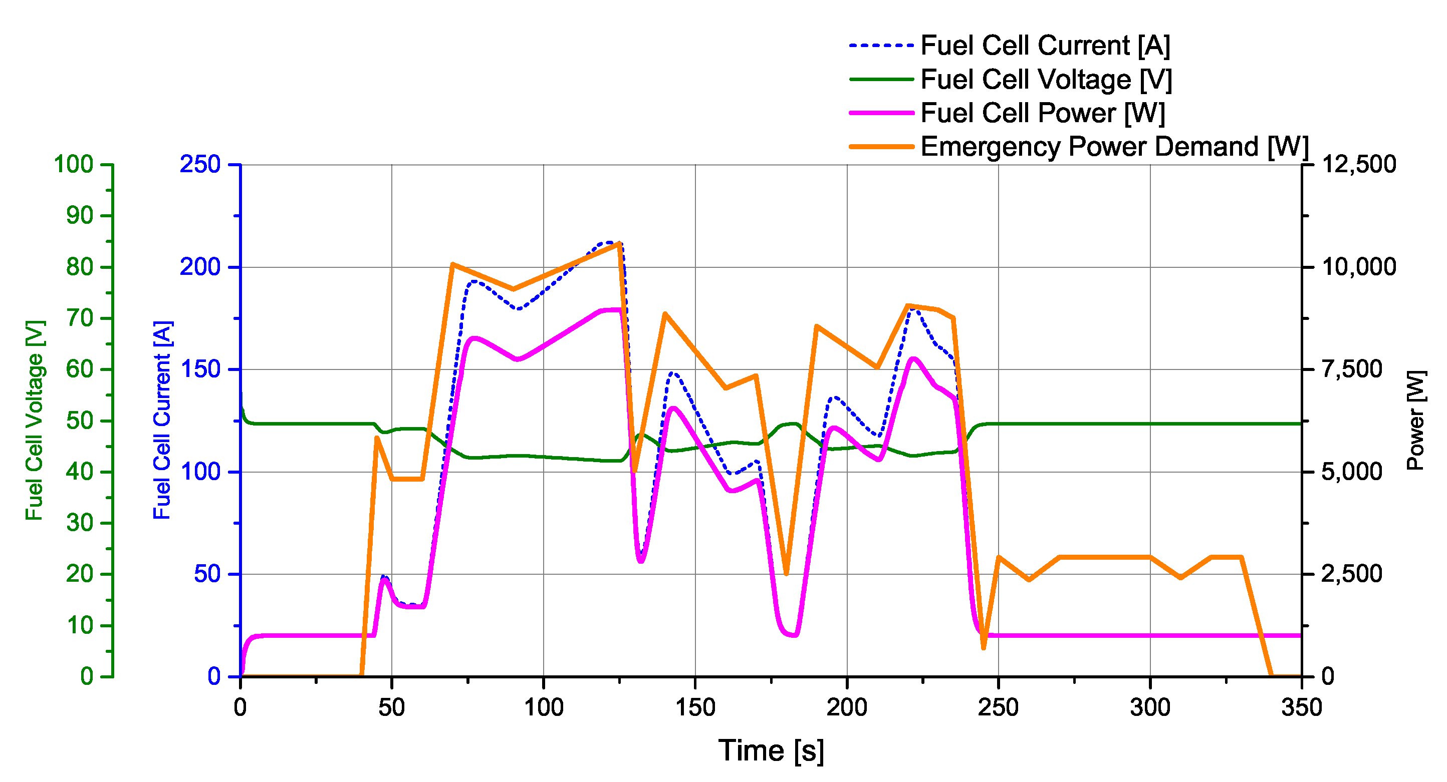
The current and voltage variations during the simulation for the sine cosine algorithm of the fuel cell are shown in
Figure 15. Limit values for the fuel cell were 850 and 8800 W. It was observed that the voltage changes remained within 40–55 V and the fuel cell current increased up to approximately 220 A.
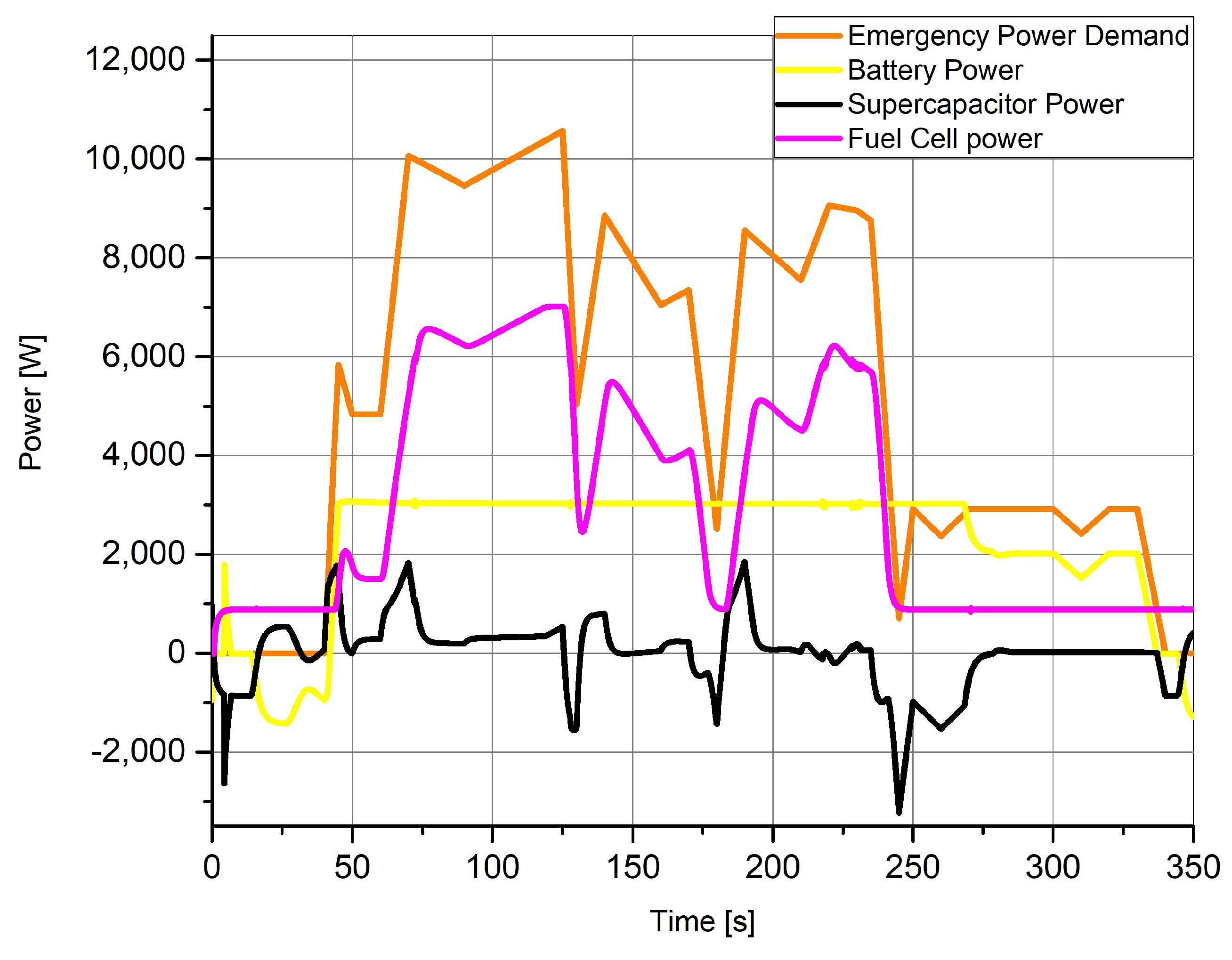
For the sine cosine algorithm, the change of power sharing throughout the simulation is shown in
Figure 16. There was no power demand until about 45 s. After 45 s, there was a sudden increase in demand power and most of this sudden power demand was met by the supercapacitor. It was then seen that the demand power was mostly met by the fuel cell stack and the remaining amount was shared between the battery and the supercapacitor.
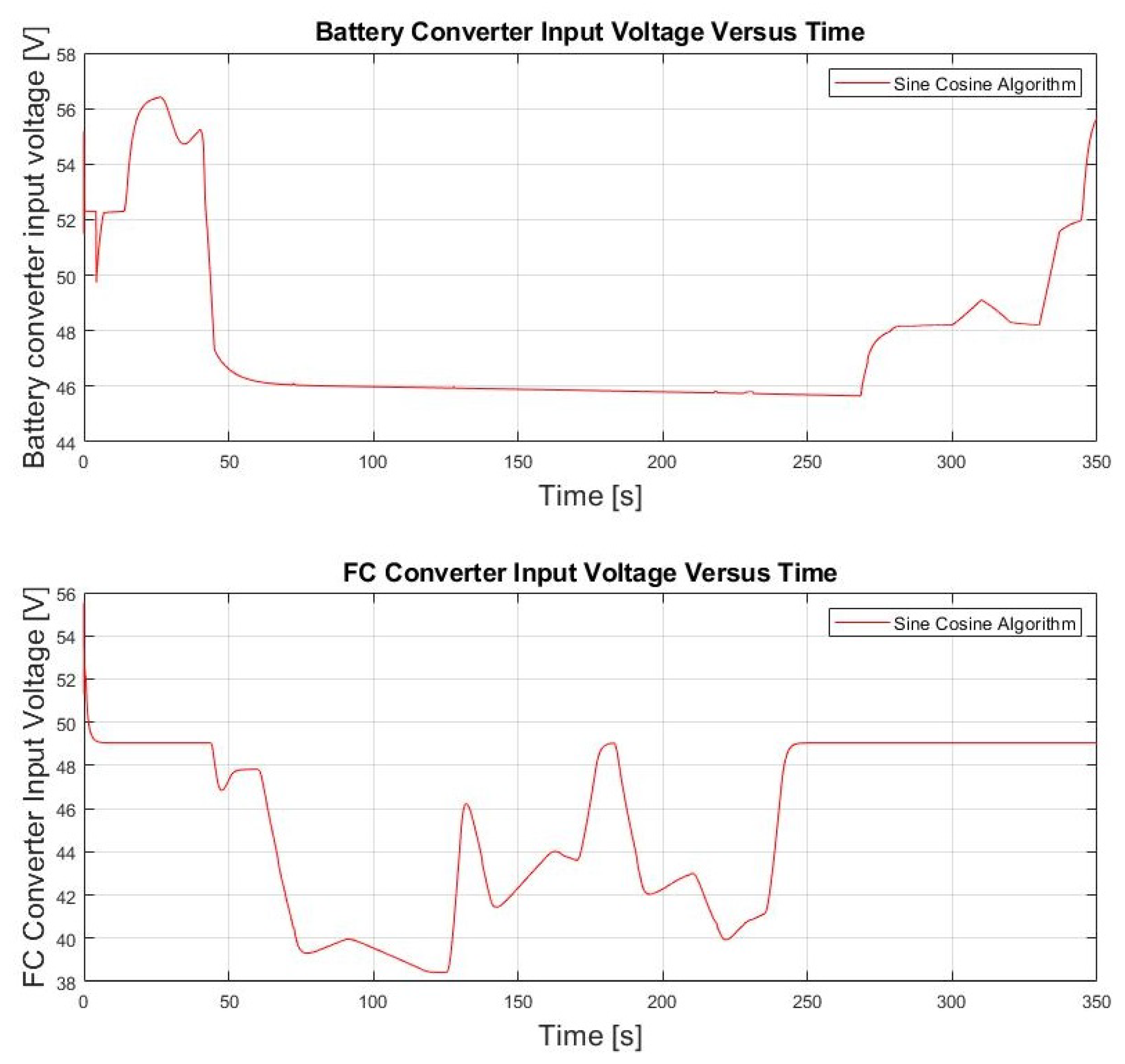
The battery and fuel cell converter input voltage is shown in
Figure 17. The operating voltage of the system is 270 V and the lowest voltage value (
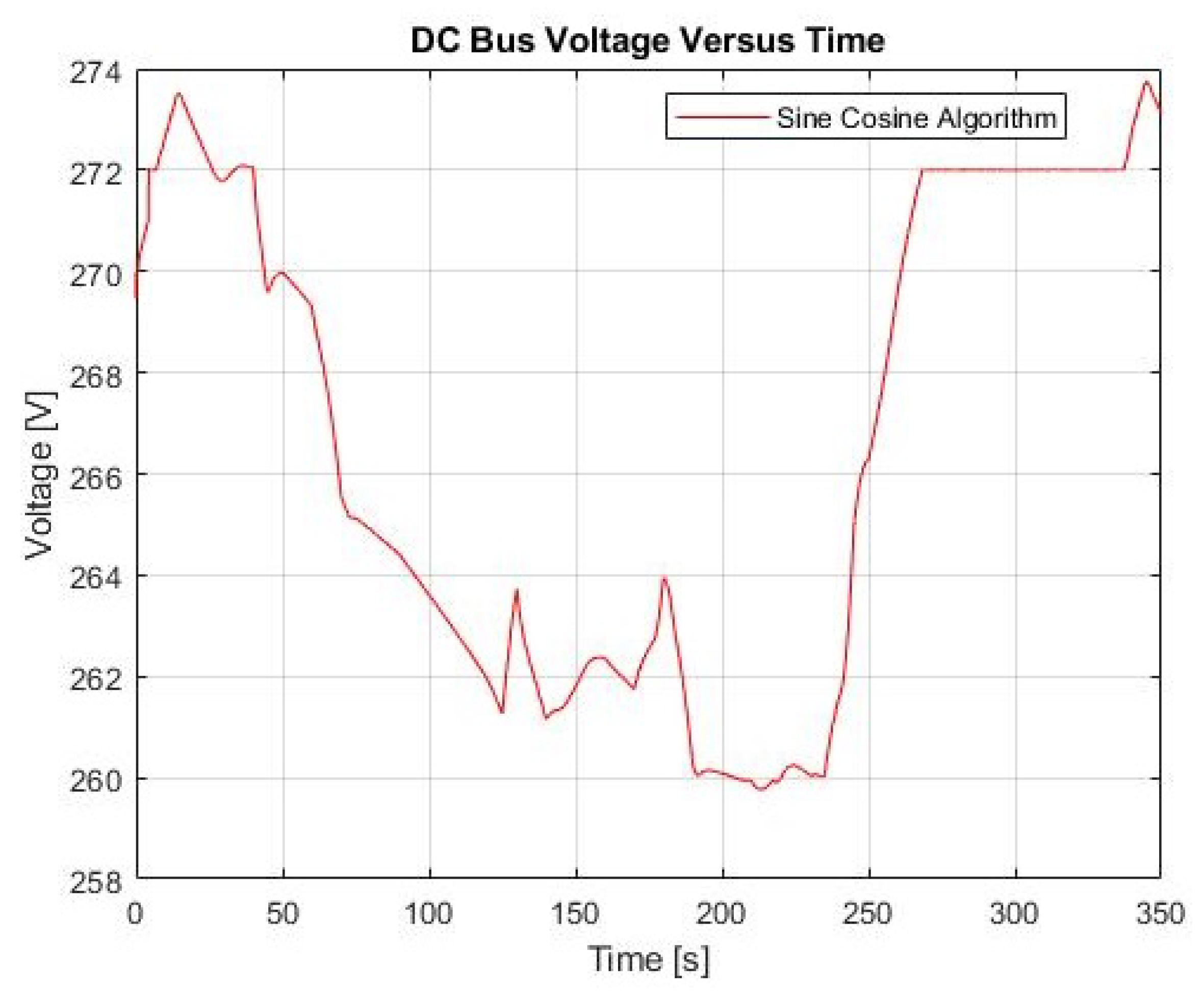
) of the system is 268 V. The converter input voltage of the fuel cell remained in the operating voltage range 35–55 V, and the converter input voltage of the battery remained in the range of 44–57 V. DC bus voltage change is shown in
Figure 18. Accordingly, the DC bus voltage varies within 258–274 V.
Among the studies in the literature for the benchmark model used in this study, the Coyote Algorithm method provided the lowest result in terms of hydrogen consumption with 19.37 g [
26]. In this study, very close results were obtained for the same model. It can be concluded that the meta-heuristic algorithms in the same family present similar results. For this reason, it is understood that the solution time or the computational burden is more important for meta-heuristic algorithms from the same family.
5. Conclusions
In this study, the active energy management and optimization of a hybrid system consisting of battery, fuel cell stack, and supercapacitor were investigated. The purpose of this hybrid system is to meet the demand power that an aircraft may need in an emergency case. The active energy management in the study was conducted with the help of DC/DC converters. The purpose of the energy management of this hybrid system is to minimize hydrogen consumption. At the same time, it ensures that the battery state of charge (SOC) states remain within the desired limits. The active energy management of the hybrid system was conducted with ant lion optimizer (ALO), moth-flame optimization (MFO), dragonfly algorithm (DA), sine cosine algorithm (SCA), multi-verse optimizer algorithm (MVA), particle swarm optimization (PSO), and whale optimization algorithm (WOA) algorithms. The contribution of this study is that the ant lion algorithm, moth-flame optimization algorithm, and sine cosine algorithms were applied to this hybrid system for the first time. Sine cosine algorithm provided the best result in terms of hydrogen consumption (19.2250 g) and computational time (350 s). Although nearly similar results were obtained from meta-heuristic algorithms, it was observed that they are superior to equivalent consumption minimization strategy (ECMS) and classical PI control strategies in terms of hydrogen consumption. The order of meta-heuristic algorithms according to minimum hydrogen consumption is as follows: SCA, WOA, MFA, MVA, ALO, and DFA. In addition, the sine cosine algorithm provided the lowest calculation time. In future studies, energy management can be performed with more detailed models that include the external dynamics of the problem. Studies on reducing the computational burden can be examined to increase real-time applicability. In addition, reducing the stresses on each source and removing voltage fluctuations can be investigated in a hybrid system.


