Article

An Evaluation Method for Dry Friction Damping of Ring Damper in Gas Turbine Engines under Axial Vibration

1
School of Energy and Power Engineering, Beihang University, Beijing 100191, China
2
Jiangxi Research Institute, Beihang University, Nanchang 330096, China
*
Author to whom correspondence should be addressed.
Aerospace 2021, 8(10), 302; https://doi.org/10.3390/aerospace8100302
Submission received: 25 August 2021 / Revised: 1 October 2021 / Accepted: 14 October 2021 / Published: 15 October 2021
(This article belongs to the Special Issue Vibration Control for Space Application)

Abstract

:
The blisks and labyrinth seals in gas turbine engines are typical rotating periodic structures. Vibration problems will inevitably occur during the operation, which can easily lead to High Cycle Fatigue failure of the structure. Adding ring damper is an effective means of structural vibration reduction. The damper uses the dry friction of the contact surface to dissipate the vibration energy, improve the damping of the system, and then reduce the vibration response of the structure. The structures have a nodal diameter and modal shape, and the forced vibration often presents the characteristics of traveling wave. In this paper, an evaluation method for dry friction damping of ring damper under the axial component of traveling wave vibration is established. For the given vibration stress at the critical location, the equivalent damping ratio provided by the ring damper is calculated based on the friction energy dissipation and the damping characteristic curve that is the equivalent damping ratio varying with the vibration stress is obtained. This method can avoid calculating the nonlinear dry friction forced response and is suitable for the design stage. The damping of split ring dampers with rectangular section for one blisk and labyrinth seal is analyzed in this paper. It is shown that rotating speed, friction coefficient, section area and material density significantly influence the damping characteristics. There are many factors affecting the damping characteristics of the damping, so it is necessary to comprehensively consider various factors and multiple modes for vibration reduction design.

1. Introduction

The blade integrated disks (blisks) and labyrinth seals in gas turbine engines are typical rotating periodic structures. These rotors bear the static stress caused by high centrifugal load and thermal load, and the vibration stress caused by changing load, which can easily cause High Cycle Fatigue (HCF) failure. Thus, it is necessary to reduce the static stress and control the vibration stress at its dangerous location on the rotors [1]. However, the excitation frequency range of the rotors is wide, and the excitation order is complex, so it is difficult to avoid all resonance. Dry friction damping technology, which dissipates vibration energy through contact surface friction, is an effective means to reduce vibration stress in gas turbine engines [2].
The blisks and labyrinth seals often install ring dampers to suppress vibration. The ring is installed in the groove specially processed in the main structure in the form of disk and shell. During the working process, the ring is tightly pressed in the groove by centrifugal force to maintain contact with the main structure. The vibration of the rotors will lead to the relative sliding of the contact surface and then reduce the vibration stress of the structure through friction energy dissipation. Different from the discrete damping structures such as underplatform damper and shroud, the ring is a circumferential continuum (a split ring will cause the disconnection in the local area), as shown in Figure 1, and the friction force between the ring and the main structure is a distributed force along the circumferential direction. The underplatform damper is often regarded as a rigid body [3], the damping ring is a deformed body, and the ring moves coherently with the main structure.
Dry friction damping design depends on the grasp of structural dynamics and contact, focusing on the resonance frequency, damping and vibration level [4]. Combined with the developed contact models [5], the dynamic response of the dry friction system can be obtained. In 2008, Phadke and Berger [6] used the Direct Time Integration method to calculate the forced response of the blade with underplatform damper, of which the time cost is too high. Harmonic Balance Method (HBM) [7] converts variables into the frequency domain for response solution, which improves the calculation efficiency. Cameron and Griffin [8] put forward the Alternative Frequency Time (AFT) method to describe the contact phenomenon more effectively in the time domain and then convert it back to the frequency domain for solution. In 2005, Laxalde [9] used the lumped parameter method to solve the amplitude frequency response for the blisk ring in combination with MHBM and AFT and analyzed the damping effect under the conditions of strong and weak coupling between blade and disk. In 2007, he [10,11] used the cyclic symmetry to reduce multistage bladed disk system, simplified the ring with the beam model, calculated the contact force by using the Dynamic Lagrange method, and obtained the nonlinear response of the system. In 2008 [12], the amplitude frequency response curve was calculated using the nonlinear modes. In 2010, he and Thouverez et al. [13] optimized the vibration prediction method to improve the damping design from the aspects of ring thickness, slip/stick alternating state of contact surface and multiple damping rings, etc. Baek and Epureanu [14] in 2017 expressed the friction force on the contact surface as equivalent stiffness and equivalent damping on the basis of the reduction model for one blisk with ring, which greatly simplified the calculation of forced response. Tang and Epureanu et al. [15,16] proposed a reduction model for random mistuning bladed disk and calculated the forced response. In 2019, they [17] used the linear mode to obtain the frequency difference under different contact states, and investigated the influence of different geometry of the ring on the vibration reduction effect; the position and thickness of the ring are the main factors. V-shaped and bi-conical rings can provide a high vibration reduction effect. Alford [18,19] studied the resonance-induced fatigue, friction-induced vibration, self-excited vibration and other failure problems of labyrinth seals. Niemotka et al. [20] developed the friction work of rings by analyzing the vibration characteristics of combined structure. Buyukatamand et al. [21,22] investigated the effects of speed, contact normal force and cross-section size of the ring on friction energy dissipation. Lopez et al. [23,24] studied the friction energy caused by the relative sliding of the contact surface between the ring and the hub under different vibration conditions, investigated the influence of number and modes of ring on the vibration reduction effect and carried out experimental verification. In addition, Krack et al. used nonlinear modes to deal with the dry friction problem from the perspective of non-conservative system [25,26].
The current research mainly focuses on the solution of forced response and the establishment of a more efficient and accurate Reduced Order Model. Considering that the typical steady-state stress and vibration stress range of the rotors are basically known, from the view of vibration stress and energy dissipation, this paper develops an analysis method and process of damping effect of rings, which avoids the calculation of nonlinear response. For the dangerous modes of structures, the friction energy and equivalent damping ratio provided by the ring are calculated by using the relative motion of the contact surface and the Coulomb friction model, and the damping characteristic curve that is the equivalent damping ratio provided by the ring varying with the vibration stress of the structure is given. The method proposed in this paper is computationally efficient and suitable for the vibration reduction design stage which needs multiple iterations.

2. Equivalent Damping Analysis of Dry Friction

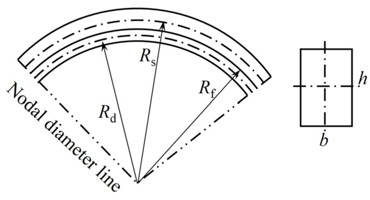
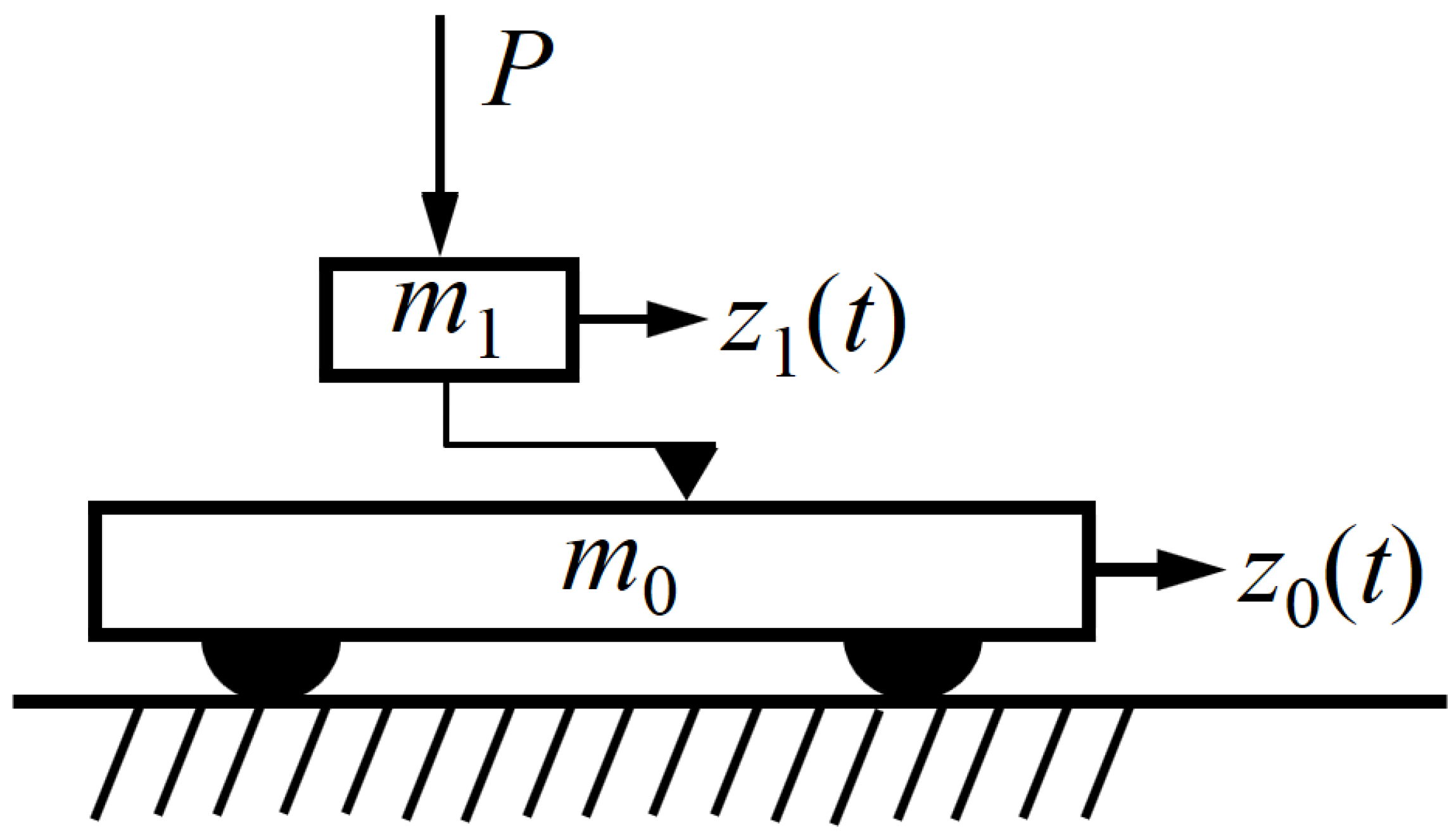
2.1. Equation of Motion

The structures in this paper are rotating periodic structures. The dynamics of tuning structures can be analyzed by a single sector using cyclic symmetric boundary conditions [27,28], so as to simplify the computation. The nonlinear motion equation of a single-sector finite element model considering contact is
M u ¨ ( t ) + C u ˙ ( t ) + k u ( t ) = f e ( t ) f c ( u ( t ) , u ˙ ( t ) )
in which M, C and K are the mass, damping and stiffness matrices of structure, respectively; u(t) is the displacement; fe(t) is the exciting force; fc is the nonlinear contact force including normal force and friction force. fc is not zero only in the DoFs of the contact surface. It can also be seen from the EoM that dry friction damping includes vibration and contact. In this paper, the dry friction damping provided by the damping ring is a dimensionless parameter, which can be directly added and subtracted algebraically with other damping such as the material damping.
The rotating periodic structures often have the nodal-diameter (ND) modal shape, and their vibration presents traveling wave. It may be assumed that the structure has N nodal diameter traveling wave vibration, and the axial displacement of the structure at position θ and time t at the ring groove where the damping ring is installed is assumed to be
z 0 ( θ , t ) = A cos ( N θ ω d t )
where A is the amplitude of axial displacement and ωd is circular frequency, as shown in Figure 2. Different from stationary wave (or standing wave) vibration z0(θ, t) = Acos()cos(ωdt), there is no time when the displacement of the whole structure is zero in traveling wave vibration. Due to the cyclic symmetry of structure and mode, the structure with N nodal diameter vibration can be divided into 4N substructures (0, π/(2N)] along the circumferential direction. The whole ring can be obtained by the motion and friction energy consumption of one substructure.

2.2. Energy Dissipation

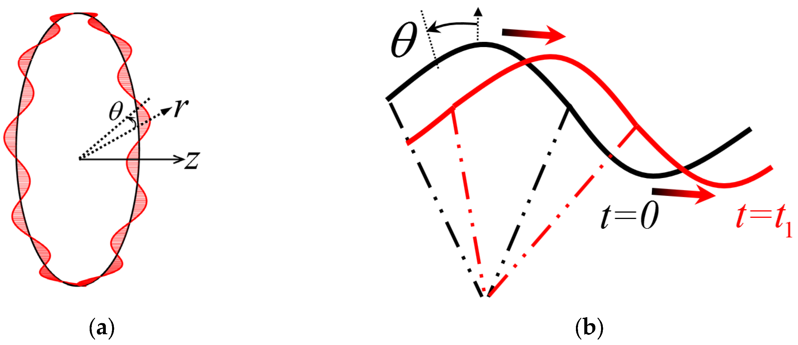
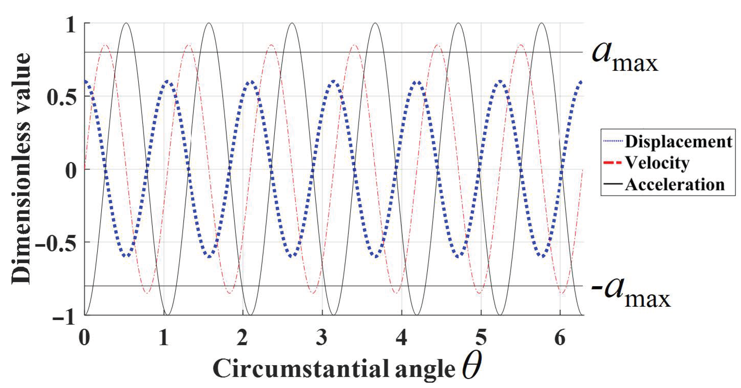
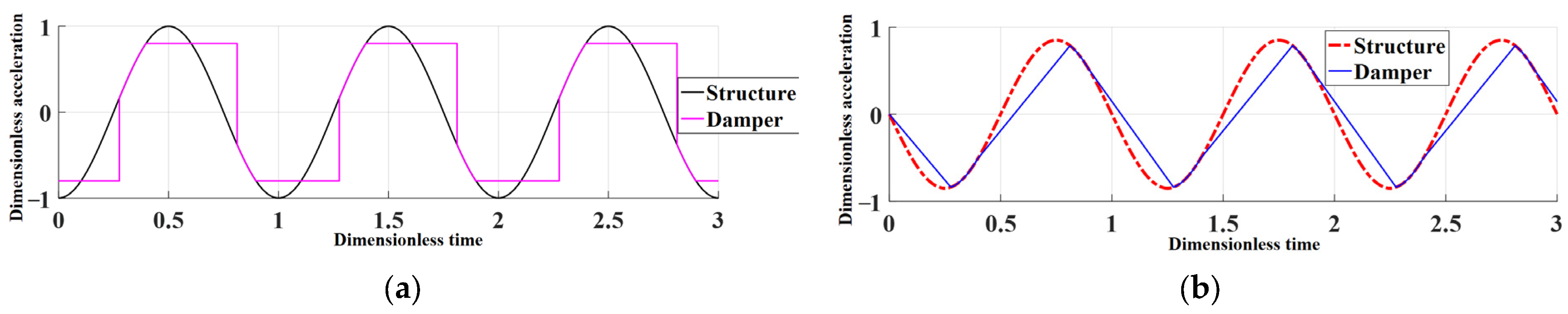
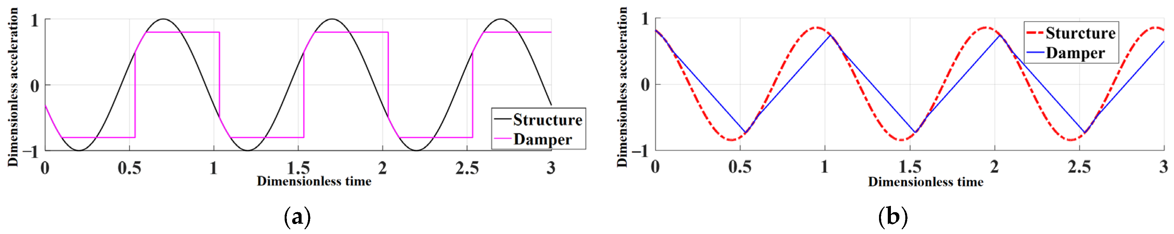
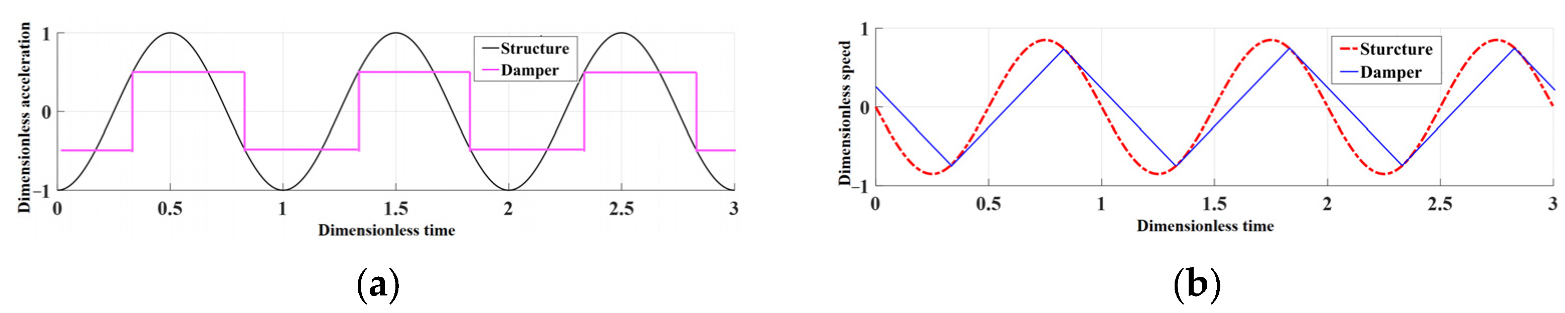
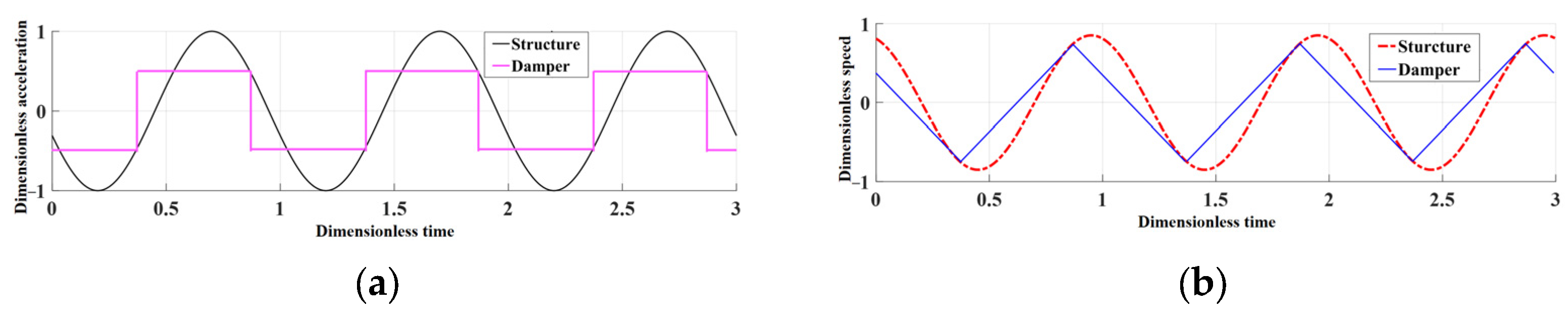
2.2.1. Relative Motion Analysis

The mechanism of dry friction damping is that the friction generated by the relative motion between the contact surfaces dissipates the vibration kinetic energy so as to increase the damping of the system. The basic principle of relative motion caused by the axial displacement of rotating periodic structure and ring can be explained by the motion of plate-slider system shown in Figure 3. A mass slider m1 forced by pressure P is placed on the horizontally moving plate m0, and the plate drives the slider through friction; if the friction force is not enough to balance the inertial force of the slider, the contact surface will slide relatively, and the friction force will dissipate energy. Lopez [23,24] gave the periodic motion behavior and energy dissipation of the plate-slider system in detail.
The plate slider system is extended to the rotating periodic structure. By two radial sections with included angle dθ to cut the micro-element, the main structure and ring are divided into several groups of discrete mass-elements, and each group obeys the motion of the plate-slider system. The following assumptions are adopted: (1) Ignore the axial stiffness of the ring, that is, the axial stiffness between the discrete mass elements of the ring; (2) At the resonance frequency, the damping ring has no own mode, and its axial motion is only affected by friction and inertial force; (3) The vibration phase angle of the ring at the same circumferential position is the same; (4) the classical Coulomb friction model is used. Assuming that the motion of the main structure is not affected by the ring, it can be obtained from the displacement equation (2) that the axial velocity and acceleration at position θ and time t are, respectively,
z 0 ( θ , t ) = A cos ( N θ ω d t ) .
Taking the 6 ND vibration mode as an example, Figure 4 shows the displacement, velocity and acceleration of the main structure at t = 0. In the figure, amax is the maximum acceleration that the maximum static friction can provide to the damping ring. The axial movement of the ring is z1(θ, t), and its motion is determined by friction and inertial force.

2.2.2. Motion of Ring

As the plate-slider system, when the normal load on the contact surface is constant, the small amplitude makes the acceleration of the ring small, so the static friction force is enough to balance the inertial force of the ring during the whole vibration cycle. This situation is called the full-stick state. With the increase in amplitude, when the inertia force exceeds the maximum friction force in a vibration cycle, the contact surface will be in a state of alternating stick and slip, which is called stick–slip state. When there is no stick state in a vibration cycle, it is called full-slip state. Since the full-stick state does not produce friction energy dissipation, only the other two states are analyzed below.

Stick−Slip State

The friction caused by the movement of the main structure causes the movement of the ring. If the static friction is not enough to provide the inertia force of the ring, it will lead to slip; otherwise, it will be in a stick state. In a vibration cycle, the contact surface will be in a stick or slip state alternately. It is assumed that the contact pressure in the Coulomb friction model is evenly distributed during vibration, and the ring is not separated from the groove. The contact pressure caused by interference assembly is much less than the centrifugal force. If the contact pressure caused by interference is ignored here, the maximum acceleration amax provided by the maximum static friction can be expressed as
a max = μ Ω 2 R d
where μ is friction coefficient and Ω is rotating speed of rotor.
(1)
Stick phase
The velocity and acceleration of the ring in the stick state are the same as those of the main structure, which can be expressed as
z ˙ 1 ( t ) = z ˙ 0 ( t ) = ω d A sin ( N θ ω d t ) z ¨ 1 ( t ) = z ¨ 0 ( t ) = ω d 2 A cos ( N θ ω d t ) } t 0 ( θ ) < t < t 1 ( θ )
where t0(θ) is the starting time of the stick phase, while t1(θ) is the end time of the stick phase.
(2)
Transition from stick phase to slip phase
When the acceleration of the damping ring reaches the maximum acceleration provided by the maximum friction, the state becomes slip, that is
| z ¨ 1 ( θ , t 1 ) | = | ω d 2 A cos ( N θ ω d t 1 ) | = μ Ω 2 R d
which can be rewritten as
| cos ( N θ ω d t 1 ) | = μ Ω 2 R d A ω d 2 = k .
k can be considered as a dimensionless parameter for friction force. It is worth pointing out that the meaningful condition of the above formula is k ≤ 1. When k > 1, it means that the friction to keep the ring moving with the main structure is less than the maximum static friction, and the whole contact surface is in a stick state in the whole vibration cycle. When k = 1, the critical amplitude Acr that just begins to slip can be defined by
A cr = μ Ω 2 R d ω d 2
which means that at a given speed, when the amplitude of this mode is less than the Acr, the ring and the main structure always stick together, and the contact surface does not dissipate vibration energy according to the Coulomb friction model. When the amplitude is greater than the Acr, the contact surface begins to slide relatively, and the friction dissipates the vibration energy.
(3)
Slip phase
When the contact surface is in slip state, the ring is affected by constant sliding friction force, and the acceleration is constant. The expressions of the velocity and acceleration of the ring in the slip phase are
z ˙ 1 ( θ , t ) = ω d A sin ( N θ ω d t 1 ) k ω d 2 A ( t t 1 ) z ¨ 1 ( θ , t ) = k ω d 2 A } t 1 ( θ ) < t < t 2 ( θ )
where t1(θ) is the starting time of the slip phase, while t2(θ) is the end time of the slip phase.
(4)
Transition from slip phase to stick phase
During the slip phase, when the speed of the ring is equal to the speed of the structure, the contact surface will enter the stick state again. At this time, z ˙ 1 ( θ , t 2 ( θ ) ) = z ˙ 0 ( θ , t 2 ( θ ) ) , i.e.,
ω d A sin ( N θ ω d t 1 ) k ω d 2 A ( t 2 t 1 ) = ω d A sin ( N θ ω d t 2 ) .
That is,
sin ( N θ ω d t 1 ) k ω d ( t 2 t 1 ) = sin ( N θ ω d t 2 ) .
After that, the contact surface enters the stick state again and moves circularly according to the above motion law. t1(θ) and t2(θ) give the slip phase of the first half cycle, which can be solved by Equations (7) and (11), respectively.
t 1 = N θ ± arccos ( ± k ) ω d
sin ( N θ ω d t 1 ) k ω d ( t 2 t 1 ) = sin ( N θ ω d t 2 )
t3(θ) and t4(θ) give the slip phase of the second half cycle, i.e.,
t 3 ( θ ) = t 1 ( θ ) + π ω d ,   t 4 ( θ ) = t 2 ( θ ) + π ω d
Taking two circumferential positions θ = 0°, θ = 12° as an example, shown in Figure 5, Figure 6 and Figure 7, the changes of acceleration and velocity of structure and ring with time in stick–slip state (k = 0.8) are shown. It can be seen that in a vibration cycle, there is a stage in which the structure and the ring move together, and the stick and slip stages occur alternately.

Full-Slip State

When the value of parameter k in Equation (7) is small enough that there is no stick phase in the whole vibration cycle, it is called full-slip state. The motion of the slip phase of the ring still satisfies Equation (9), and it can be considered that the starting time and the end time of the stick phase are the same, i.e.,
t 2 ( θ ) = t 3 ( θ ) = t 1 ( θ ) + π ω d
By Equations (10) and (15), there is
sin ( N θ ω d t 1 ) k ω d π ω d = sin ( N θ ω d t 2 )
which can be
± k π = 2 sin ( N θ ω d t 1 )
Thus, the time period of slip phase is obtained.
Taking θ = 0°, θ = 12° shown in Figure 5, Figure 8 and Figure 9, the changes of acceleration and velocity of structure and ring with time in stick–slip state (k = 0.5) are shown. In a vibration cycle, it is no longer alternating between stick and slip stage, but always in slip stage.

Critical State between Full-Slip and Stick-Slip

In the critical state between full-slip and stick–slip, t1(θ), solved by Equations (7) and (17), are equal.
{ k = | cos ( N θ ω d t 1 ) | ± k π = 2 sin ( N θ ω d t 1 )
Furthermore, the critical dimensionless friction parameters kcr can be obtained by
k cr = 1 1 + ( π / 2 ) 2 0.537 .
kcr means that when k > kcr, there is no stick phase in the whole vibration cycle, that is, full-slip state; when kcr < k < 1, the slip phase and stick phase occur alternately in a vibration cycle, that is, the stick–slip state.

2.2.3. Relative Displacement at the Contact Surface

When the steady state is reached, use the velocity of slip phase within half one period to express the axial relative displacement Δs of ring and structure through integral as
Δ s ( θ ) = 2 t 1 ( θ ) t 2 ( θ ) [ z ˙ 1 ( θ , t ) z ˙ 0 ( θ , t ) ] d t = 2 ω d A t 1 ( θ ) t 2 ( θ ) [ ω d k ( t t 1 ( θ ) ) + cos ( ω d t 1 ( θ ) ) cos ( ω d t ) ] d t = 2 ω d A { ω d k [ t 2 ( θ ) t 1 ( θ ) ] 2 / 2 + cos ( ω d t 1 ( θ ) ) [ t 2 ( θ ) t 1 ( θ ) ] 1 ω d [ sin ( ω d t 2 ( θ ) ) sin ( ω d t 1 ( θ ) ) ] }

2.2.4. Energy Dissipated by Friction

From the perspective of energy, dry friction damping can reduce vibration by friction energy generated by the relative movement of contact surface. The damping effect can be evaluated by the ratio of friction energy dissipation to system vibration energy. The friction energy dissipation of a vibration period can be obtained by integrating the product of the axial relative displacement and the sliding friction force. It is worth noting that there ae 4N substructures for N ND vibration. Through symmetry, there is
E f = 0 2 π μ P R f d θ Δ s ( θ ) = 4 N 0 π 2 N μ P R f Δ s ( θ ) d θ
where P is the normal force of contact surface per unit length, and here only the normal force caused by centrifugal force is considered, assuming that it is uniform and constant, so P can be P = ρdhbΩ2Rd and Rf is the radius of the contact surface. ρd = 7.8 g/cm3 is the density of the ring, Rd is the radius of the ring, b is the axial width of the ring section, h is the radial height of the ring section and Ω is the rotational angular velocity. When the ring slides, the friction force per unit length is μP.

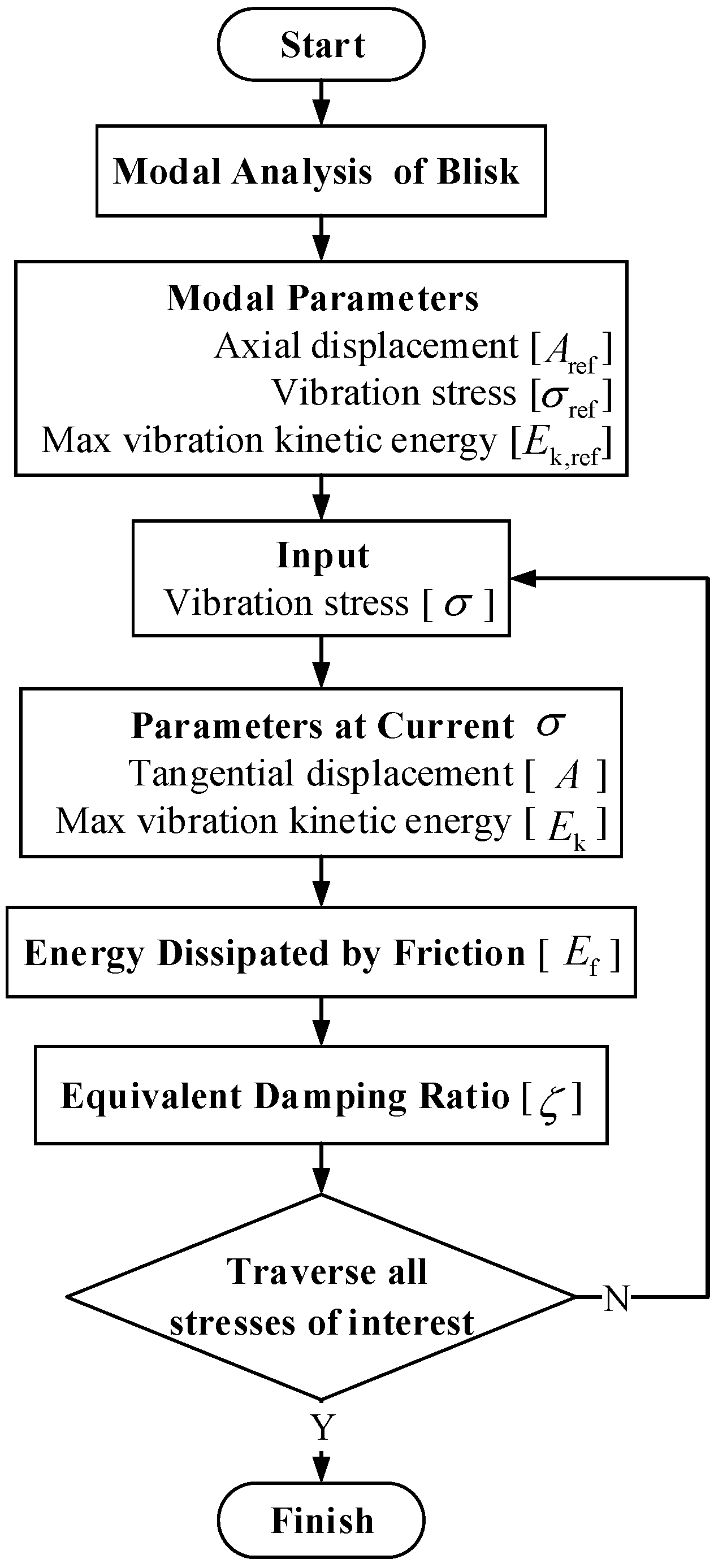
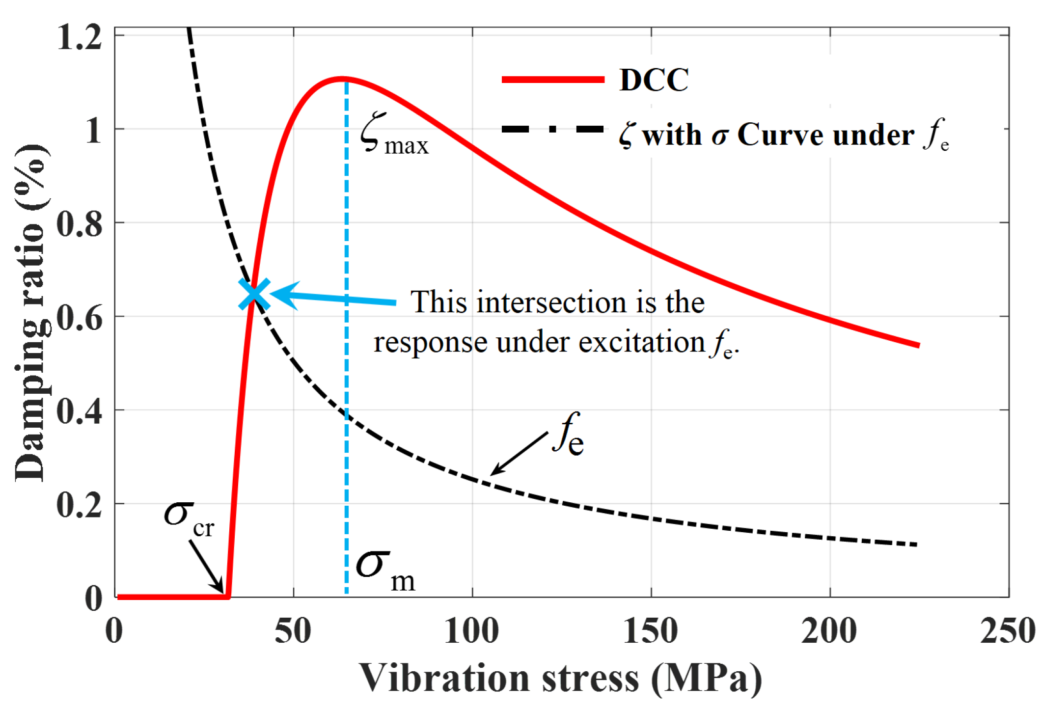
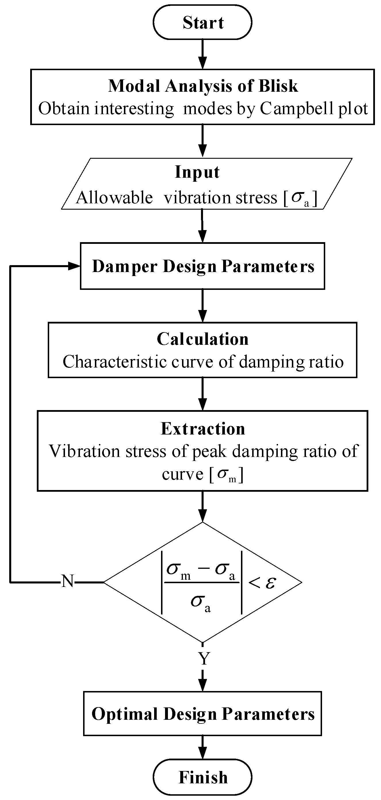
2.3. Equivalent Damping Ratio
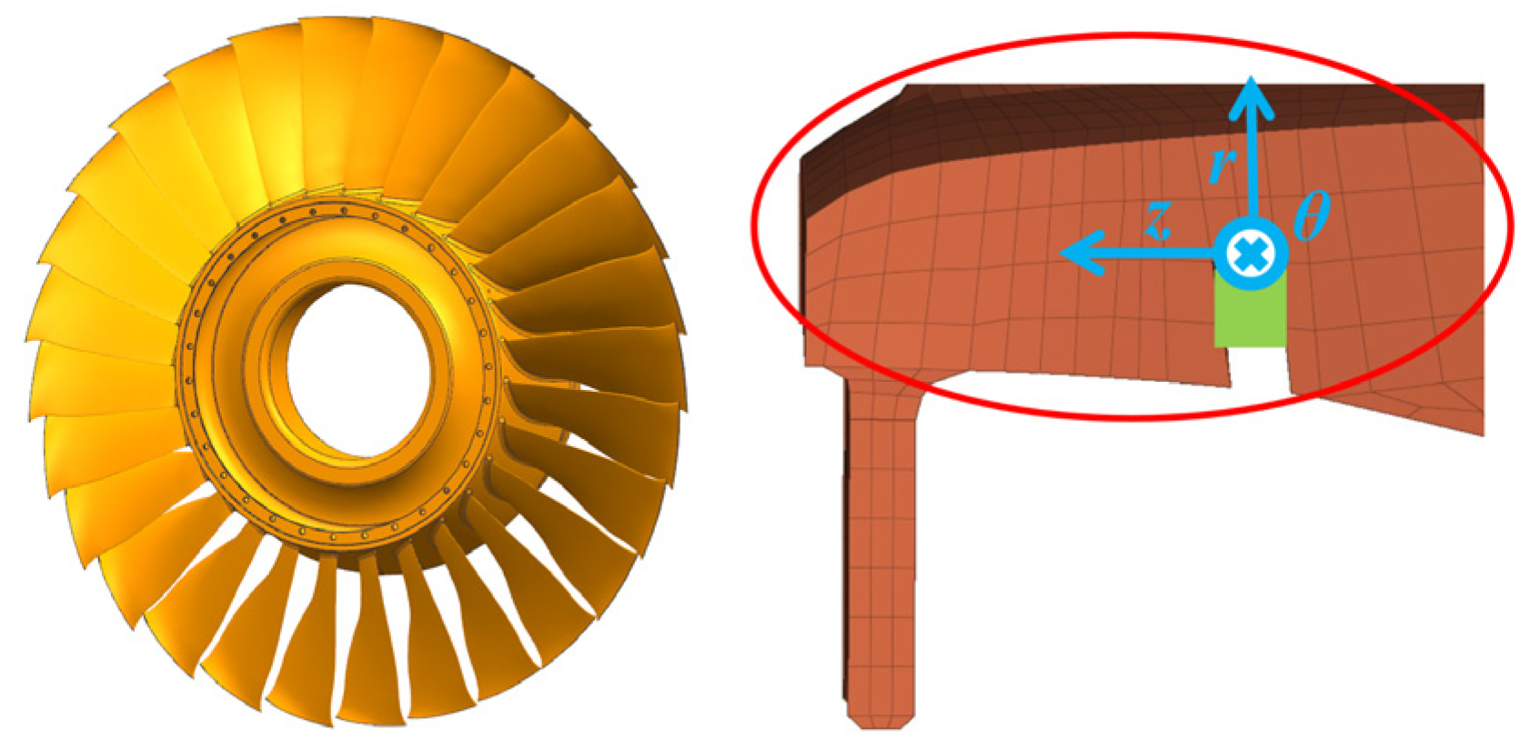
The loss factor can be expressed as the proportion of energy dissipation in a vibration cycle to vibration energy, which is often used to compare the damping effect of engineering materials [29], i.e.,
η = E f 2 π E 2 ζ .
The vibration energy of the system can be expressed as the maximum kinetic energy or maximum potential energy in a cycle. This paper selects maximum kinetic energy Ek, then the equivalent damping ratio provided by the ring can be expressed as
ζ = E f 4 π E k .
For a given mode of the structure, under the condition of small deformation, modal displacement Aref, vibration stress σref, vibration kinetic energy Ek,ref as well as actual displacement A, vibration stress σ and vibration kinetic energy Ek satisfy
A A ref = σ σ ref = E k E k , r e f .
With vibration stress σ at the critical location of the main structure, displacement A and kinetic energy Ek can be calculated. The friction energy dissipation Ef under the corresponding amplitude is calculated by Equation (21), so that the equivalent damping ratio ζ provided by the ring under the current vibration stress can be calculated by Equation (23). The Damping Characteristic Curve can be obtained by changing the vibration stress. Figure 10 shows the detailed calculation flow of the damping characteristics of the ring.
The Damping Characteristic Curve (DCC) is the damping ratio provided by the system with the vibration stress of the main structure at critical location, as shown in Figure 11. The critical vibration stress σcr is the resonant vibration stress of the structure at critical location when the ring begins to provide damping. Peak damping ratio ζmax is the maximum damping rati, and σm is the corresponding vibration stress. In addition, through the intersection of the curve of damping ratio on the vibration stress under excitation fe and DCC, the response under this excitation can be obtained. The vibration-reduction design flow of ring based on damping characteristics is shown in Figure 12. Adjust the design parameters of the ring to meet the design requirements: within the typical working range, the peak damping ratio shall be as large as possible, and the critical vibration stress shall be relatively small.

3. Case Study

3.1. Damping Characteristics of Ring for Blisk

The damping characteristics of the split ring with rectangular section for one blisk is analyzed. Apply centrifugal load and thermal load to the blisk shown in Figure 13 for pre-stress modal analysis: during static analysis, the displacement boundary condition at the installation surface is the deformation of the two-dimensional model of high-pressure turbine rotor; in modal analysis, the displacement boundary condition is changed to circumferential and axial displacement constraints. The diagram of frequency on the cruise rotating speed is Figure 14a and the Campbell diagram is Figure 14b. Take the dangerous mode of 3 ND first Bend as an example for vibration reduction analysis. The displacement and stress results of this mode are shown in Figure 15a,b, respectively, and the modal parameters extracted are shown in Table 1.
The parameters of the blisk and ring are shown in Figure 16, and the specific values are shown in Table 2.
According to the method described in part 2, the dry friction damping characteristics of the blisk for 3 ND first bending mode are analyzed by using the above parameters, and Figure 17 shows the DCC. The damping ratio and ζmax provided by the ring are very small, and the critical stress σcr that means the ring begins to provide damping is so large that it exceeds the strength limit of the material. Within the typical vibration stress range of the blade (such as 200 MPa), the dry friction damping ratio provided by the ring is zero. This is due to the weak coupling between the blade and disk. It is the blade that mainly vibrates, while the vibration of the disk is very small and the relative displacement of the contact surface is too small.

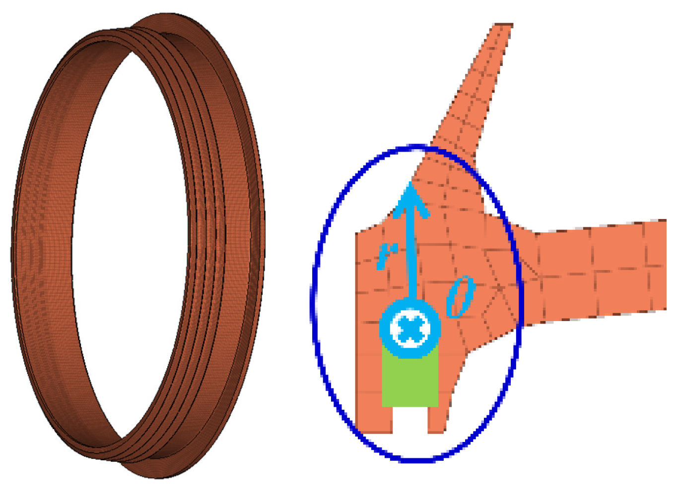
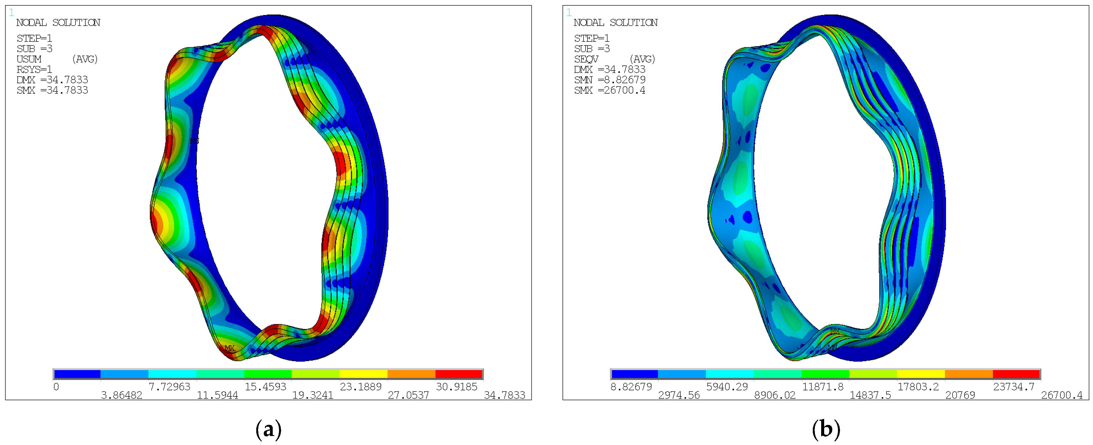
3.2. Damping Characteristics of Ring for Labyrinth Seal

The damping characteristics of the split ring with rectangular section for one labyrinth seal is analyzed. Apply centrifugal load and thermal load to the labyrinth seal shown in Figure 18 for pre-stress modal analysis: the displacement boundary condition at the installation surface is circumferential and axial displacement constraints, and the Coriolis Effect is considered. Take the dangerous mode of 6 ND first order as an example for sensitivity analysis. The displacement and stress results of this mode are shown in Figure 19a,b, respectively, and the modal parameters extracted are shown in Table 3.
The parameters of the labyrinth and ring are shown in Table 4.

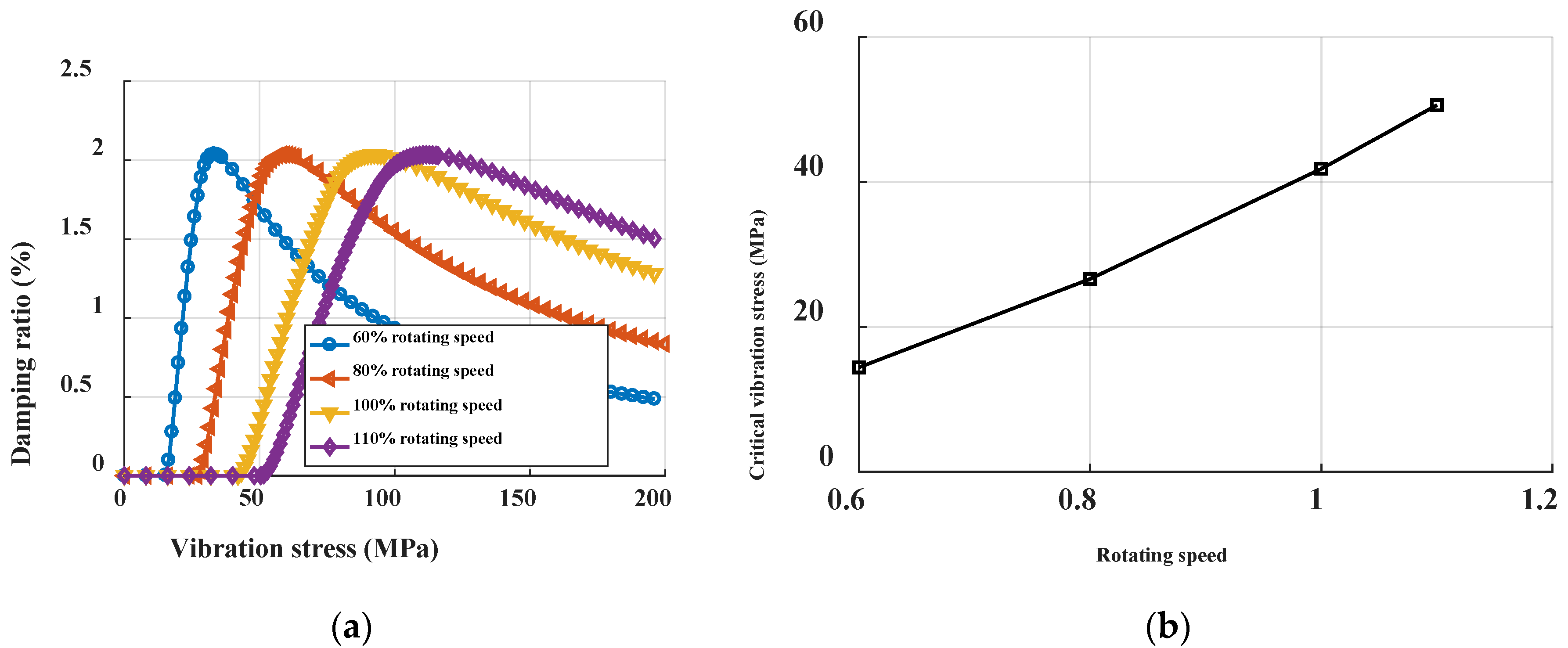
3.2.1. Rotating Speed

Noting that the operation range of rotating speed is wide, the change of speed will not only affect the natural characteristics through stress stiffening, but also affect the centrifugal force of the ring, and then change the contact normal force. Figure 20 shows the damping characteristic curves of the ring at different speeds. It can be seen that the higher the speed is, the greater the critical vibration stress is. This is because the increase in speed increases the normal force and the maximum static friction, making it more difficult for the relative slip of the contact surface to occur. With the increase in rotating speed, the peak damping ratio changes little, but its corresponding vibration stress increases, which means that the vibration level when the ring plays the best role is closely related to the rotating speed.

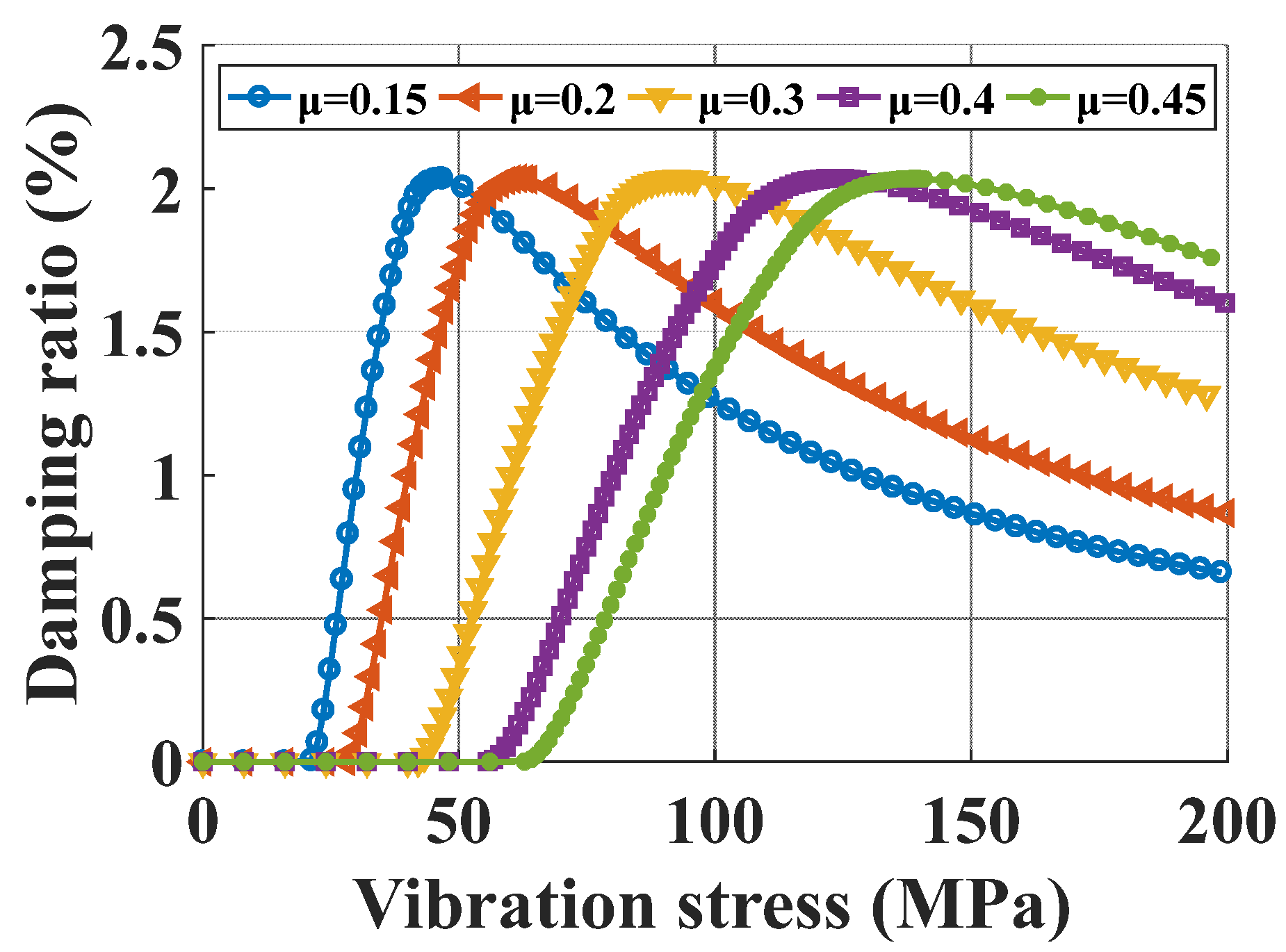
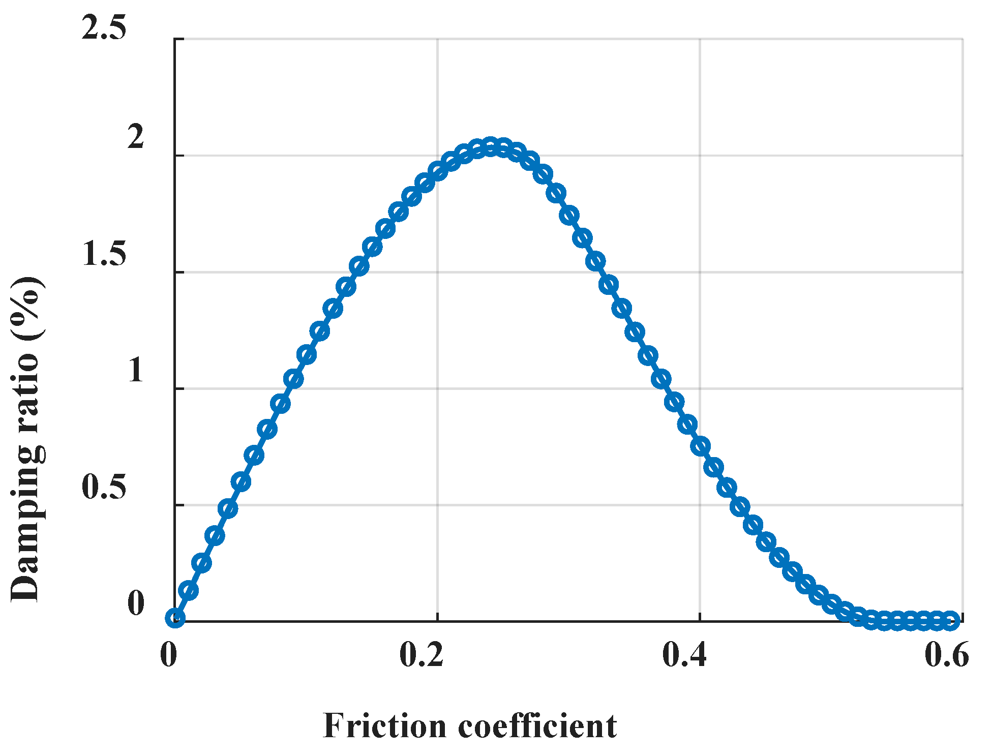
3.2.2. Friction Coefficient

As a material property, the friction coefficient belongs to the design parameter. Similar to the influence of rotating speed, the critical vibration stress is directly proportional to the friction coefficient, but the peak damping ratio is not affected, as shown in Figure 21. Figure 22 shows the optimization curve of friction coefficient. With the increase in the friction coefficient, the damping ratio first increases and then decreases, and there is an optimal friction coefficient. If the typical allowable vibration stress of the labyrinth seal is 75 MPa, the damping ratio is positively correlated with the friction coefficient. In the selection of materials, the greater the friction coefficient, the better.

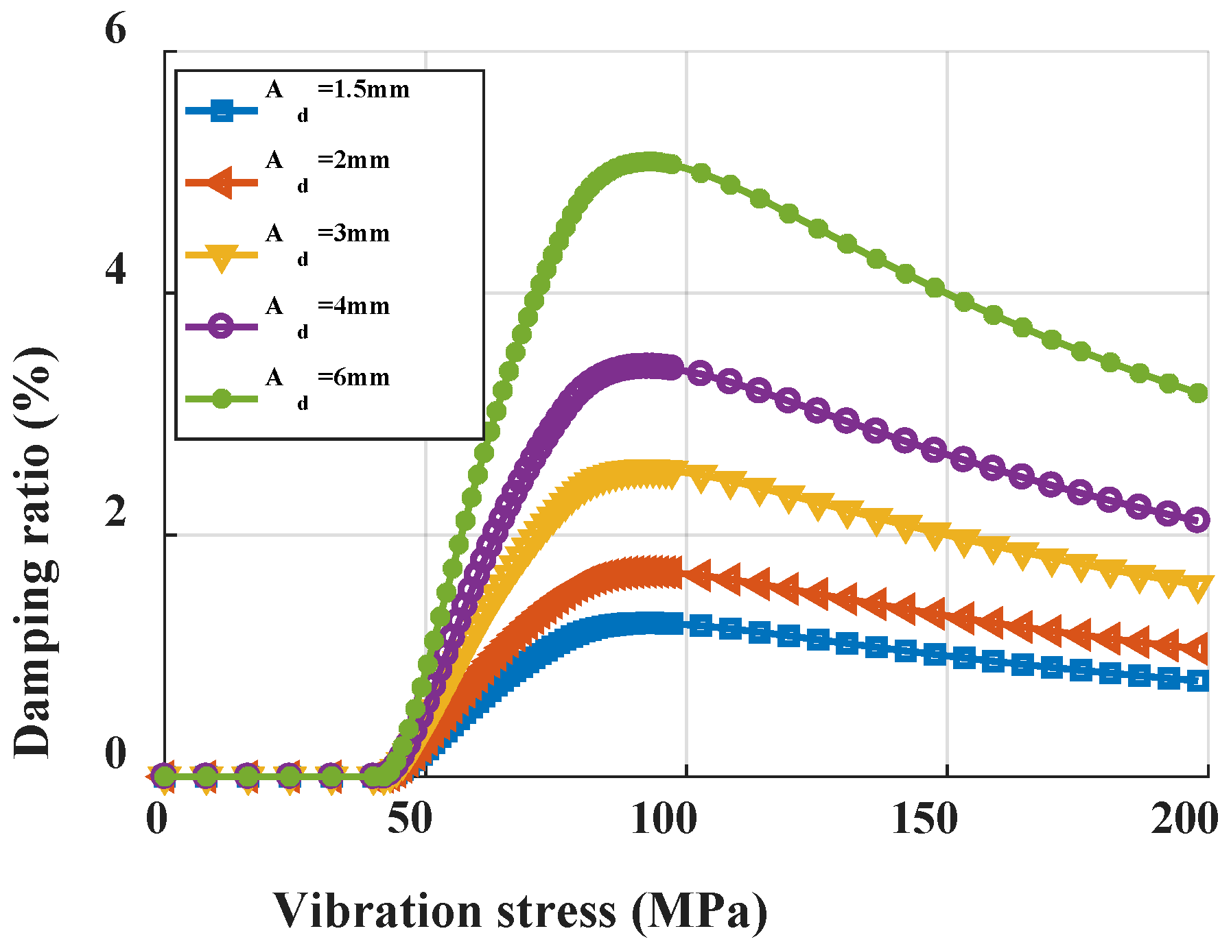
3.2.3. Cross-Section Area of the Ring

The section area of the ring directly affects its damping effect, and Figure 23 shows its effect on the damping characteristics. The damping ratio by the ring is nearly linear with its section area. The section area has little effect on the critical vibration stress, because the critical vibration stress is related to the ratio of friction force to inertia force. Although the inertia force and friction force of the damping ring are related to the section area, the ratio of friction force to inertia force remains basically stable. Increasing the section area is beneficial to improve the damping effect. In practical application, due to the limitation of the size of the damping groove, within the allowable range of the design, the larger the section area is, the better.

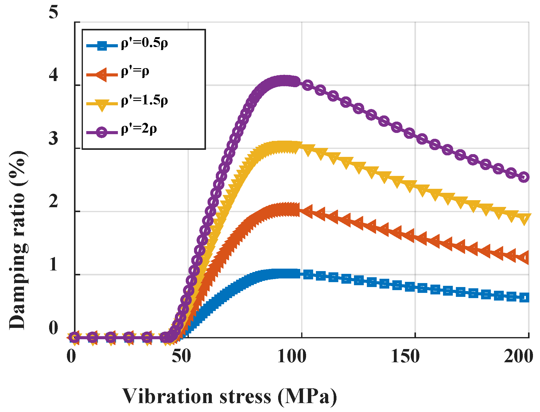
3.2.4. Density of Ring

Material density is also a design parameter, and its influence on damping characteristics is similar to that of section area, as shown in the Figure 24. It mainly affects the peak damping ratio and has little effect on the critical vibration stress. In the actual design, the maximum value shall be taken as far as possible.

4. Discussion and Conclusions

In this paper, an analytical method considering the damping characteristics of ring under axial motion is proposed for the traveling wave vibration of rotating periodic structure. The equivalent damping ratio provided by the ring is calculated by the energy method, and the damping characteristic curve is obtained. The damping characteristic curve can be used to evaluate the damping effect provided by the ring. For the focus modes, the relationship between the damping ratio and the vibration stress at the critical location is given. This method is based on linear modal analysis without calculating nonlinear forced response. It is simple and time-saving and is suitable for early design stage. The design objective is that the ring can provide as much damping ratio as possible under the typical allowable vibration stress.
In this paper, the damping characteristics of the rectangular cross-section split ring damper are studied by taking the blisk and the labyrinth seal as an example. For the analyzed blisk, the damping effect provided by the ring is very limited under the typical vibration stress range. For the analyzed labyrinth seal, the sensitivity of the design parameters of the damping ring is analyzed for the 6 ND mode, and the effects of rotating speed, friction coefficient, cross section area and material density on the damping characteristics are investigated.
The influence of friction coefficient on damping ration is compared with the results from the forced response analysis by HFT with ROM in [14], as shown in Figure 25. For comparison, the vibration displacement and equivalent damping ratio of both two methods are normalized with regard to the case of μ = 0.1. When μ ≤ 0.3, they two show good consistency, while the error is relatively large when μ = 0.4. Generally, the tendency of ring damper is consistent with the literature. However, although the tendency of optimization curve for friction coefficient is similar with the reference [14], there is still not a small error for the value. The possible reasons come from many aspects, such as the inconsistency of the models of two methods, e.g., the inaccuracy of the proposed method in this paper.
The key assumptions used in this paper are discussed below. Firstly, the axial stiffness of the ring is ignored, and the Coulomb friction model is adopted, that is, the normal force on the contact surface is evenly distributed along the circumferential direction and remains unchanged during the vibration. It is true that this is not the case. The reason for this paper is to simplify the calculation on the one hand and to consider that the centrifugal force caused by the high-speed rotation of the rotor is huge on the other hand. Secondly, this method assumes that the influence of ring on the vibration mode of main structure, such as blisk and labyrinth seal, can be ignored. Generally, the mass of the ring is much less than that of the main structure, and the ring has little effect on the stiffness of the main structure. Some studies [13,17,30] also show that the influence of damping ring on the resonance frequency, not the frequency response, of the main structure is less than 1%. The ring mainly dissipates vibration energy through friction to improve system damping and reduce vibration response.
The natural frequencies of structures with ring and without ring were calculated in Table 5 below. The structure with ring means that the contact of ring and structure is in the stick state. The structure without ring means that ring and structure are in separation. The natural frequency of both these two cases can be calculated by linear modal analysis. The frequency difference between the two states is almost within 1.0%. The difference of the focused mode, 6 nodal diameter, is 0.24%. Thus, we proposed that the ring has a limited impact on the resonance frequency. For the focused 6 nodal diameter mode, the equivalent stiffness of main structure and split ring damper by classic lumped parameter model were calculated, kst and kd, respectively. The result is that kst = 2694kd, so herein the axial stiffness of the ring can be ignored.
Thus, this paper only considers the axial vibration, that is, the friction energy dissipation caused by the axial component of vibration displacement, while in practice, there is the relative motion caused by the radial and circumferential components. Finally, the method and process in this article are aimed at single-mode vibration reduction analysis. The methods need to be developed in the future for the multiple modes.

Author Contributions

Conceptualization, S.G.; methodology, S.G. and Y.W.; software, S.G.; writing—original draft preparation, S.G.; funding acquisition, Y.W. All authors have read and agreed to the published version of the manuscript.

Funding

This research was funded by the National Science and Technology Major Project No. 2017-IV-0002-0039.

Institutional Review Board Statement

Not applicable.

Informed Consent Statement

Not applicable.

Data Availability Statement

Not applicable.

Acknowledgments

The authors would like to acknowledge Lin Shi and Chenhong Du for their responses to the questions.

Conflicts of Interest

The authors declare no conflict of interest.

References

  1. Srinivasan, A.V. Flutter and resonant vibration characteristics of engine blades. J. Eng. Gas Turbines Power 1997, 119, 742–775. [Google Scholar] [CrossRef]
  2. Ewins, D. Control of vibration and resonance in aero engines and rotating machinery—An overview. Int. J. Press. Vessel. Pip. 2010, 87, 504–510. [Google Scholar] [CrossRef]
  3. Afzal, M.; Arteaga, I.L.; Kari, L. Numerical analysis of multiple friction contacts in bladed disks. Int. J. Mech. Sci. 2018, 137, 224–237. [Google Scholar] [CrossRef]
  4. Krack, M.; Salles, L.; Thouverez, F. Vibration prediction of bladed disks coupled by friction joints. Arch. Comput. Methods Eng. 2016, 24, 589–636. [Google Scholar] [CrossRef] [Green Version]
  5. Bograd, S.; Reuss, P.; Schmidt, A.; Gaul, L.; Mayer, M. Modeling the dynamics of mechanical joints. Mech. Syst. Signal Process. 2011, 25, 2801–2826. [Google Scholar] [CrossRef]
  6. Phadke, R.; Berger, E.J. Friction damping analysis in turbine blades using a user-programmed function in ansys. In Proceedings of the 12th International Symposium on Transport Phenomena and Dynamics of Rotating Machinery, Honolulu, HI, USA, 17–22 February 2008. [Google Scholar]
  7. Cardona, A.; Lerusse, A.; Géradin, M. Fast Fourier nonlinear vibration analysis. Comput. Mech. 1998, 22, 128–142. [Google Scholar] [CrossRef]
  8. Cameron, T.M.; Griffin, J.H. An alternating frequency/time domain method for calculating the steady-state response of nonlinear dynamic systems. J. Appl. Mech. 1989, 56, 149–154. [Google Scholar] [CrossRef] [Green Version]
  9. Laxalde, D.; Sinou, J.J.; Thouverez, F.; Lombard, J.P. Modeling and analysis of friction rim dampers for blisks. In Proceedings of the ASME 2005 International Design Engineering Technical Conferences and Computers and Information in Engineering Conference, Long Beach, CA, USA, 24–28 September 2005. [Google Scholar]
  10. Laxalde, D.; Thouverez, F. Non-linear vibrations of multi-stage bladed disks systems with friction ring dampers. In Proceedings of the ASME 2007 International Design Engineering Technical Conferences and Computers and Information in Engineering Conference, Las Vegas, NV, USA, 4–7 September 2007. [Google Scholar]
  11. Laxalde, D.; Thouverez, F.; Lombard, J.-P. Vibration control for integrally bladed disks using friction ring dampers. In Proceedings of the GT2007 ASME Turbo Expo 2007: Power for Land, Sea and Air, Montreal, QC, Canada, 14–17 May 2007; pp. 255–265. [Google Scholar] [CrossRef]
  12. Laxalde, D.; Gibert, C.; Thouverez, F. Experimental and numerical investigations of friction rings damping of blisks. In Proceedings of the ASME Turbo Expo 2008: Power for Land, Sea and Air, Berlin, Germany, 9–13 June 2008; pp. 469–479. [Google Scholar] [CrossRef] [Green Version]
  13. Laxalde, D.; Thouverez, F.; Lombard, J.-P. Forced response analysis of integrally bladed disks with friction ring dampers. J. Vib. Acoust. 2010, 132, 011013. [Google Scholar] [CrossRef] [Green Version]
  14. Baek, S.; Epureanu, B.I. Reduced-order modeling of bladed disks with friction ring dampers. J. Vib. Acoust. 2017, 139, 061011. [Google Scholar] [CrossRef]
  15. Tang, W.; Epureanu, B.I. Nonlinear dynamics of mistuned bladed disks with ring dampers. Int. J. Non-Linear Mech. 2017, 97, 30–40. [Google Scholar] [CrossRef]
  16. Tang, W.; Baek, S.; Epureanu, B.I. Reduced-order models for blisks with small and large mistuning and friction dampers. J. Eng. Gas Turbines Power 2016, 139, 012507. [Google Scholar] [CrossRef]
  17. Tang, W.; Epureanu, B.I. Geometric optimization of dry friction ring dampers. Int. J. Non-Linear Mech. 2018, 109, 40–49. [Google Scholar] [CrossRef]
  18. Alford, J.S. Protection of labyrinth seals from flexural vibration. J. Eng. Power 1964, 86, 141–147. [Google Scholar] [CrossRef]
  19. Alford, J.S. Nature, causes, and prevention of labyrinth air seal failures. J. Aircraft 1975, 12, 313–318. [Google Scholar] [CrossRef]
  20. Niemotka, M.A.; Ziegert, J.C. Optimal design of split ring dampers for gas turbine engines. J. Eng. Gas Turbines Power 1995, 117, 569–575. [Google Scholar] [CrossRef]
  21. Buyukataman, K. A theoretical study on the vibration damping of aircraft gearbox gears. In Proceedings of the 27th Joint Propulsion Conference, Sacramento, CA, USA, 24–26 June 1991. [Google Scholar] [CrossRef]
  22. Buyukataman, K.; Kazerounian, K. Vibration damping of aircraft gearbox gears part II. In Proceedings of the AIAA/SAE/ASME/ASEE 31st Joint Propulsion Conference, San Diego, CA, USA, 10–12 July 1995. [Google Scholar]
  23. Lopez, I.; Nijmeijer, H. Prediction and validation of the energy dissipation of a friction damper. J. Sound Vib. 2009, 328, 396–410. [Google Scholar] [CrossRef]
  24. López, I.; Busturia, J.; Nijmeijer, H. Energy dissipation of a friction damper. J. Sound Vib. 2004, 278, 539–561. [Google Scholar] [CrossRef]
  25. Krack, M.; Scheidt, L.P.-V.; Wallaschek, J. A method for nonlinear modal analysis and synthesis: Application to harmonically forced and self-excited mechanical systems. J. Sound Vib. 2013, 332, 6798–6814. [Google Scholar] [CrossRef]
  26. Krack, M. Nonlinear modal analysis of nonconservative systems: Extension of the periodic motion concept. Comput. Struct. 2015, 154, 59–71. [Google Scholar] [CrossRef]
  27. Thomas, D.L. Dynamics of rotationally periodic structures. Int. J. Numer. Methods Eng. 1979, 14, 81–102. [Google Scholar] [CrossRef] [Green Version]
  28. Petrov, E.P. A Method for use of cyclic symmetry properties in analysis of nonlinear multiharmonic vibrations of bladed disks. J. Turbomach. 2004, 126, 175–183. [Google Scholar] [CrossRef]
  29. Rao, S.S. Mechanical Vibrations, 5th ed.; Prentice Hall: Hoboken, NJ, USA, 2011. [Google Scholar]
  30. Zucca, S.; Firrone, C.M.; Facchini, M. A method for the design of ring dampers for gears in aeronautical applications. J. Mech. Des. 2012, 134, 091003-1-10. [Google Scholar] [CrossRef]
Figure 1. Split ring with rectangular cross-section before and after installation.
Aerospace 08 00302 g001
Figure 2. Schema of nodal diameter traveling wave vibration of rotating periodic structures: (a) Instantaneous axial displacement; (b) Axial displacement at different times.
Aerospace 08 00302 g002
Figure 3. Schema of plate-slider system.
Aerospace 08 00302 g003
Figure 4. Schema of motion of structure with 6 ND at t = 0.
Aerospace 08 00302 g004
Figure 5. Schema of motion of structure with 6 ND at t = 0 (two positions).
Aerospace 08 00302 g005
Figure 6. Motion at θ = 0° in stick–slip state (k = 0.8): (a) Acceleration; (b) Velocity.
Aerospace 08 00302 g006
Figure 7. Motion at θ = 12° in stick–slip state (k = 0.8): (a) Acceleration; (b) Velocity.
Aerospace 08 00302 g007
Figure 8. Motion at θ = 0° in stick–slip state (k = 0.5): (a) Acceleration; (b) Velocity.
Aerospace 08 00302 g008
Figure 9. Motion at θ = 12° in stick–slip state (k = 0.5): (a) Acceleration; (b) Velocity.
Aerospace 08 00302 g009
Figure 10. Flow of the damping characteristics of the ring.
Aerospace 08 00302 g010
Figure 11. Damping characteristic curve.
Aerospace 08 00302 g011
Figure 12. Design analysis and procedures of vibration suppression of ring.
Aerospace 08 00302 g012
Figure 13. Blisk-ring dry friction system.
Aerospace 08 00302 g013
Figure 14. Natural vibration characteristics for the blisk: (a) Frequency on ND at cruise rotating speed; (b) Campbell diagram.
Aerospace 08 00302 g014
Figure 15. 3 ND first Bend mode for the blisk: (a) Displacement vector sum; (b) Von Mises stress.
Aerospace 08 00302 g015
Figure 16. Schema of parameters for the system.
Aerospace 08 00302 g016
Figure 17. DCC of ring for the blisk (3 ND first Bend).
Aerospace 08 00302 g017
Figure 18. Labyrinth seal-ring dry friction system.
Aerospace 08 00302 g018
Figure 19. 6 ND first mode for the labyrinth seal: (a) Displacement vector sum; (b) Von Mises stress.
Aerospace 08 00302 g019
Figure 20. Damping characteristics at different rotating speeds for labyrinth seal: (a) DCC; (b) Critical vibration stress.
Aerospace 08 00302 g020
Figure 21. Damping characteristics at different friction coefficients for labyrinth seal.
Aerospace 08 00302 g021
Figure 22. Optimization of friction coefficient (admissible vibration is 75 MPa).
Aerospace 08 00302 g022
Figure 23. Damping characteristics at different section areas for labyrinth seal.
Aerospace 08 00302 g023
Figure 24. Damping characteristics at different densities of ring for labyrinth seal.
Aerospace 08 00302 g024
Figure 25. Comparison of the proposed method with ref [14]: (a) Normalized damping ratio along with normalized vibration displacement; (b) Normalized displacement along with friction coefficient.
Aerospace 08 00302 g025
Table 1. Modal parameters for the blisk.
ParameterValue
Order3 ND first Bend
Frequency/Hz461.50
Axial amplitude Aref/mm0.193
Max equivalent stress σref/MPa1661
Max kinetic energy Ek,ref/J4204
Table 2. Parameters for the blisk-ring system.
ParameterValue
Friction coefficient μ0.3
Rotating speed Ω/(r/min)11,723
Radius of contact surface Rf/mm184.2
Young’s modulus of ring E/GPa210
Radius of free split ring Rd,fr/mm188.7
Radius of assembled split ring Rd/mm181.2
Height of section of ring h/mm6
Width of section of ring b/mm1.5
Table 3. Modal parameters for the labyrinth seal.
ParameterValue
Order6 ND first
Frequency/Hz1446.10
Axial amplitude Aref/mm31.000
Max equivalent stress σref/MPa26,700
Max kinetic energy Ek,ref/J41,895
Table 4. Parameters for the labyrinth seal-ring system.
ParameterValue
Friction coefficient μ0.3
Rotating speed Ω/(r/min)2227
Radius of contact surface Rf/mm245.7
Young’s modulus of ring E/GPa210
Radius of free split ring Rd,fr/mm250.7
Radius of assembled split ring Rd/mm243.7
Height of section of ring h/mm2
Width of section of ring b/mm1.2
Table 5. Frequencies of two cases for the labyrinth seal-ring system.
OrderLabyrinth with RingLabyrinth without RingFrequency
Difference
FrequencyNDFrequencyND
11365.9051374.905−0.65%
21390.2051399.105−0.64%
31446.1061442.6060.24%
41467.7061464.1060.25%
51471.0041486.504−1.04%
61498.4041513.804−1.02%
71689.3071670.8071.11%
81708.6071690.0071.10%
91748.2031764.203−0.91%
101778.8031794.503−0.87%
Publisher’s Note: MDPI stays neutral with regard to jurisdictional claims in published maps and institutional affiliations.

