Article

In-Flight Test Campaign to Validate PIO Detection and Assessment Tools

1
Deutsches Zentrum für Luft und Raumfahrt (German Aerospace Center), Rotorcraft Department, Institute of Flight Systems, 38108 Braunschweig, Germany
2
National Research Council Canada (NRC), Flight Research Laboratory, Ottawa, ON K1A 0R6, Canada
3
Deutsches Zentrum für Luft und Raumfahrt (German Aerospace Center), Flight Experiments, 38108 Braunschweig, Germany
*
Author to whom correspondence should be addressed.
Aerospace 2020, 7(9), 136; https://doi.org/10.3390/aerospace7090136
Submission received: 19 August 2020 / Revised: 4 September 2020 / Accepted: 7 September 2020 / Published: 10 September 2020
(This article belongs to the Special Issue Rotorcraft)

Abstract

:
This paper describes a joint research campaign conducted by the German Aerospace Center (DLR) and the National Research Council Canada (NRC) to explore methods and techniques to expose rotorcraft pilot-induced oscillations (PIOs) during flight testing. A flight test campaign was conducted at NRC using the Bell 205 experimental aircraft. Results show that, particularly for the lateral axis, ADS-33 tasks can be successfully applied to expose PIO tendencies. Novel subjective and objective criteria were used during the test campaign. PIO prediction boundaries of the objective phase-aggression criteria (PAC) detection algorithm were validated through results obtained. This was the first use of PAC with data recorded in-flight. To collect subjective feedback, the aircraft–pilot coupling (APC) scale was used. This was the first use of the novel scale in-flight and received favourable feedback from the evaluation pilot. Modifications to ADS-33 mission tasks were found to successfully improve the ability to consistently expose PIOs.

1. Introduction

Aircraft/rotorcraft pilot couplings (A/RPCs) are defined as adverse, unwanted phenomena originating from anomalous and undesirable couplings between the pilot and the vehicle [1]. The term A/RPC encompasses all unfavourable vehicle responses that results from pilot control actions, whether active or passive, within the control loop. The most recognized form of A/RPC is the pilot-induced oscillation (PIO). The term refers to an oscillatory response which is characterised by an active pilot in the control loop. A PIO requires the following pre-requisites to exist;
  • An active pilot attempting to control the aircraft within the control loop.
  • Unfavourable and undesirable response of the vehicle.
  • An event or ‘trigger’ which causes oscillations to occur.
A good definition to distinguish between pilot commanded and pilot-induced oscillations is given in Ref. [2]. In the former case, the pilot drives the oscillations. In the latter case, the pilot is driven by the oscillations. Due to the requirement of an active pilot-in-the-loop, PIOs typically occur between 1–10 rad/s [3]. Oscillations at higher frequencies typically involve a passive pilot, so called pilot-assisted oscillations (PAO, Ref. [4]). These types of oscillations are typically the result of flexible aircraft dynamics or biodynamic response and are beyond the scope of the current study.
An overview of RPC events which have occurred during testing and operations is contained in [5]. In addition, PIO/PAOs have recently been cited as the cause for a number of fatal accidents during flight testing. In an accident of the Bell 525, biodynamic feedback caused PAO phenomena [6]. The fatal accident of the AW609 was found to be caused by divergent oscillations resulting from coupling between the pilot and the flight control system during descending flight [7].
PIOs are also often not directly cited as the cause of accidents. Often the focus of analysis following PIO events are the vehicle dynamics. Changes in vehicle dynamics may often be attributed as the direct cause of the oscillations. However, it is also equally important to observe the other variables and the situation where the PIO has occurred. As stated by McRuer and Jex [8], four additional variables exist: task variables, environmental variables, operator-centred variables and procedural variables. One problem found when performing PIO analysis and prediction is the difficulty in determining these variables. Although many elements can be modelled (i.e., dynamic environment), a range of variables cannot be accurately modelled (i.e., operator fatigue and motivation). For this reason, full scale in-flight testing is still required to ensure PIO-free vehicles and ‘care-free’ handling qualities (HQs). A goal of this research effort is to improve PIO testing techniques to ensure that these variables are accounted for.
Examples of research efforts in the field regarding RPCs include high fidelity modelling of aeroelastic couplings ([9,10]), identification of pilot biodynamics and models ([11,12,13]), development of prediction and detection tools ([14,15]) and development of design guidelines ([16,17]). The research effort described in this paper concerns procedures and methods to ensure that PIO tendencies are exposed during test and evaluation efforts and not during operations. Subsequently, the aim was to develop suitable manoeuvre definitions, subjective assessment methods and objective measures for flight testing.
As investigated in previous research [18,19,20], in this effort mission task elements (MTEs) and the approaches defined to determine HQ deficiencies are used to expose underlying PIO tendencies. Previous research has shown that tasks may require modifications to improve their usefulness exposing PIOs [21,22]. Results showed that using standard tasks defined in HQ guidance specifications (i.e., ADS-33E-PRF [23]) did not always expose PIOs. These efforts were limited to simulation studies.
In the study, a number of candidate MTEs were selected. Each of these MTEs was flown using performance standards defined in ADS-33 [23]. In some cases, modifications were required to the tasks due to both the vehicle and test course layout. Modifications are described in the Flight Test Methodology section.
The paper proceeds as follows. Firstly, the test campaigns conducted using NRCs Bell 205 research helicopter are discussed, including a description of the test vehicle, configurations and control systems used for the tasks. Secondly, the objective and subjective analysis methods are discussed. Thirdly, all results from the test campaign are presented. Further results, obtained during modifications to the task performance, are discussed. Finally, conclusions and recommendations are provided.

2. Test Campaigns

The following section defines the aircraft, its control system configuration and the test environment used to perform investigations.

2.1. Aircraft Description

The NRC Bell 205 (C-FPGV) is an experimental fly-by-wire (FBW) research facility operated by the National Research Council of Canada (NRC). The aircraft is used to conduct HQ, control system and autonomous systems research. A single engine utility helicopter, the basic airframe features a Lycoming T-53-13A turboshaft engine (1250 SHP, takeoff rating) and has a maximum gross weight of 9500 lb. As depicted in Figure 1, the aircraft’s main rotor features a 2-bladed teetering design. During its configuration as a research helicopter, the airframe was modified to improve its utility. This included removal of the main rotor stabilizer-bar, fixing the position of the horizontal stabilizer, installation of high skid gear and the integration of Bell 212 main rotor blades. The fuel system, electrical system, mechanical flight control runs, drive-train and power-plant remain essentially unmodified.
The aircraft’s variable stability architecture incorporates a single string (simplex) FBW control system, a force-feel inceptor system and a safety system. The simplex architecture consists of a set of four experimental actuators, a non-redundant flight control computer, aircraft state sensors and flight management software. The implementation features separate flight critical electro–hydraulic actuators attached to the mechanical control runs actuators attached in parallel to the mechanical control runs and supplied by a dedicated high pressure hydraulic system. When the FBW system is engaged with the evaluation pilot in control of the aircraft, the mechanical control runs are back driven to allow the safety pilot to effectively monitor system performance. The benign HQs of the NRC Bell 205 allow the safety pilot to assume the major responsibility for flight envelope protection and safety. A health monitoring unit computer is installed to perform safety system tasks such as actuator position verification, command rate limiting, sensor consistency checking and command validation through use of a predictive algorithm. The aircraft FBW actuation system incorporates spring override mechanisms allowing the safety pilot to control the aircraft under all circumstances. To simulate flight control mechanical characteristics, a programmable digitally-controlled pilot cyclic is installed in the aircraft. Further information on the systems installed in the Bell 205 are available in [24].

2.2. Control System Configuration

The NRC Bell 205 control system was configured to allow variations in several parameters that affect PIO tendency. These parameters included different response types (Attitude Command Attitude Hold (AC) and Rate Damped (RD)), rate system bandwidth (as controlled by the rate gain) in both pitch and roll and added system time delay. The evaluation pilot station was configured with standard cyclic, collective and pedal controls during the trial. In the AC response type configuration, aircraft attitude is proportional to stick input in the lateral and longitudinal axes. In the rate response type configuration, the body axis rate of the aircraft is proportional to inceptor input in lateral and longitudinal axes. Directional and vertical control remained constant throughout the investigation. For vertical control, the collective featured heave damped response. For directional control, the pedals always featured a rate damped response type. For all axes, control characteristics were altered by adjusting gearing and damping. A simple model of the basic control structure is shown in Figure 2.
During the trial, damping ( K R ) in both longitudinal and lateral cyclic control systems was modified. This was to alter the aircraft bandwidth. All other axes remained at baseline settings throughout. The goal was to achieve control system damping configurations that resulted in closed-loop instabilities and pilot-induced oscillations during the execution of certain pilot tasks.
Higher system bandwidth could be achieved through increasing rate damping gains, which subsequently leads to a lower steady state rate and a reduced time to achieve a stabilized steady state rate for a given control input. Low damping was used to drive the control system towards closed-loop instability (below structural mode excitation) in the axis selected. Reduction in bandwidth is likely to increase PIO susceptibility, due to the slower response time following disturbance of pilot control.
Prior to the completion of MTEs, step inputs and frequency sweeps were conducted to determine the vehicle control power and bandwidth, respectively. The attitude captures were conducted for each control system configuration to characterise the response.
The NRC Bell 205 aircraft control bandwidth settings are summarised in Figure 3 for the roll and pitch axes. Four primary configurations were tested during the trial: Rate Damped (Baseline, RD), Rate Damped Low (RDL), Rate Damped High (RDH) and Attitude Command Attitude Hold (AC). HQ Levels were assessed using the ‘All Other MTE’ boundaries, contained within ADS-33E [23]. The baseline RD response provided Level 1 HQ in the roll axis and Level 2 HQs in the pitch axis. The RDL setting provided Level 2 HQs, while the RDH was found to be within Level 1 for both pitch and roll axes. The AC response provided Level 1 HQs in both axes. However, it should be considered that high phase delay was found for the AC configuration. Studies detailed in Ref. [1] showed strong susceptibility to PIO with phase delay greater than 200 ms.

2.3. Flight Test Methodology

The test methodology outlined in ADS-33E-PRF [23], primarily for HQs analysis, was used in this investigation. Previous investigations have shown the suitability of the test methodology for exposing PIO tendencies. The trial was executed at the NRC low-speed test range located at its Uplands Campus which is in proximity to the McDonald–Cartier International Airport in Ottawa (ON, Canada). It was conducted using NRC’s low-speed test range. Occurring in early March 2019, weather conditions consisted of air temperatures from −10 to −15 degrees Celsius and wind speeds from 6 to 20 knots, with the test area covered in light snow. Orange traffic pylons were used to demarcate the ADS-33 test course.
Two sorties were conducted with an approximate flight time of four hours. Due to the time available, it was only possible to complete formal evaluations using the ADS-33 MTEs with a single pilot. A second pilot acted as a safety pilot throughout the tests. Although this pilot did not conduct any formal evaluations, he supplied additional feedback regarding the test procedures and the use of subjective opinion scales discussed below. Both pilots were qualified experimental test pilots and had previously completed all manoeuvres and used all assessment scales employed during the tests.
Four MTEs were selected for the investigation: hover, lateral reposition, Pirouette and Depart–Abort. A brief description of these manoeuvres is contained here for completeness.
The hover manoeuvre is used to check the ability to transition into hover and the ability to maintain precise position, heading and altitude. The manoeuvre includes both a transition phase (45 relative to heading at 6–10 kts) and a stable precise hover (for 30 s). The successful performance is shown through visual markers located within the test area (see Figure 4). The lateral reposition manoeuvre is used to check roll and heave axis handling qualities, alongside undesirable cross couplings resulting from these axes. During the manoeuvre, the helicopter transitions from hover into a stable lateral translation, followed by a deceleration to a stabilised hover. This is performed whilst maintaining height and longitudinal position. The Pirouette manoeuvre is used to check precision in all four axes simultaneously. The manoeuvre is similar to the lateral reposition, with the exception that the translation is in a circular path and not purely laterally. The Depart–Abort manoeuvre is used to check pitch and heave axis HQs. The manoeuvre requires the pilot to initiate a forwards acceleration from hover (and reach 40–50 kts ground speed) before performing a deceleration to hover. The rotorcraft should reach a stable hover prior to a reference position given by external markers. Additionally, it is not acceptable to overshoot this point. Further and complete information addressing all manoeuvres can be found in [23].
The test course locations are shown in Figure 5. Due to Bell 205 performance and FBW limitations, it was necessary to make modifications to some ADS-33E-PRF manoeuvres. The MTEs and associated criteria are presented in Table 1. For the hover manoeuvre, the height criteria was modified due to the command validation algorithm (CVA) of the FBW system used. Lower heights result in the CVA disengaging the FBW, due to logic contained for safety purposes. The task hover height was set at 17 ft above ground. Both the lateral reposition and Pirouette were performed exclusively to the right to ensure the evaluation pilot’s view was unobstructed. The Depart–Abort was conducted as per ADS-33 requirements.
During the flights the visibility was good; however, the useable cueing environment (UCE) was degraded due to a recent light blanket of snow covering the ADS-33 course (visible in Figure 4). During initial attempts of some of the manoeuvres, including Pirouette and hover, snow due to the rotor downwash significantly affected the visibility. Before attempting any MTEs the majority of the light snow was dispersed to prevent recirculating phenomenon and impact the UCE for the MTE. In addition, to improve the usable cues on the ground, multiple run-on landings were conducted to create texture and reference marks.
In order to determine whether sufficient cues were available to the pilot to perform the MTE, additional UCE evaluations were made. These were necessary to ascertain whether the MTEs selected could be attempted given the conditions. Evaluations were conducted using the general methodology described in ADS-33 [23]. The process recommends that the UCE be conducted by three pilots and the average result is awarded. In this investigation, it was only possible (due to time limitations) to conduct the evaluation with a single pilot. This essentially modifies the process and subsequent results obtained. For the case however, this was considered acceptable, to achieve an initial understanding as to whether the cues were acceptable. The pilot confirmed this through detailed commentary.
Conditions were different on the two days, due to occasional falling snow. As a result, a UCE evaluation was conducted both on Day 1 and Day 2. The Depart–Abort task was conducted only on Day 1 and therefore the UCE was not repeated on Day 2. Results are shown in Table 2. As shown by the results, UCE was always found to be within Level 1 throughout the tests completed. Attitude cues were unaffected by the conditions.
During the Pirouette manoeuvre, the aircraft’s FBW CVA would occasionally disengage the control system due to the main rotor flap angle limit. For the same reason, it was also not possible to complete the lateral reposition using the AC system.

2.4. Analysis Methods: Objective Evaluation

Quantitative data were gathered using the flight data recording system, and a separate DLR Laptop-based payload, interfaced to the aircraft systems through an Ethernet connection. This enabled in-situ testing of the phase-aggression criteria (PAC) algorithms.
For the objective evaluation of RPCs, data from both the pilot commands, aircraft response and position were collected. Additional analysis of RPCs occurring was conducted using PAC. For completeness, PAC is briefly described here.
PAC is a real-time capable method developed to detect PIOs in-flight. It was originally conceived only as an analysis tool. However, it was shown through results that the method could be used as a prediction or early warning system, to mitigate against severe and extreme PIOs, those which could result in catastrophic failure or loss of control. The PAC method was originally based upon the pilot-inceptor workload (PIW) theory proposed by Gray [
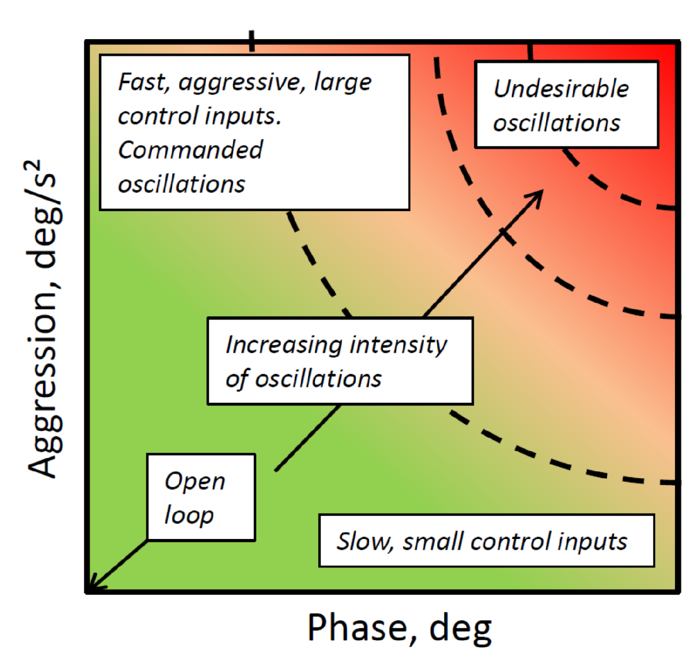
25]. PIW has been successfully used as a tool to allow pilots to assess their workload during flights at the United States Air Force Test Pilot School. It has also been used as supplementary material during flight debriefing. PIW builds a 2-D picture of the pilot control input response, by evaluating the pilot activity (duty cycle) and the pilot aggression. In various publications, the definition of aggression differs, however it is always a general measure of the input magnitude and rate of control inputs. The duty cycle is defined as the time for which the pilot is considered to be active. This is typically determined through a lower force or position threshold in the inceptor. The PIW can be either time varying (whereby on time step must be defined) or can be the result of the complete evaluation run.
PIW alone is not sufficient to observe whether PIOs occur during the flight, as there is not consideration for the vehicle output. Through definition, a mismatch between pilot and vehicle must exist [3]. For this reason, PAC extends PIW by including information regarding the phase distortion between the pilot input and the vehicle output. A schematic of the PAC is shown in Figure 6.
Through a number of simulation test campaigns, parameters to define the aggression of pilot control input ( A G ) and the phase ( Φ ) between pilot input and vehicle (rate) output were defined.
Phase ( Φ ) is calculated in the time domain, using Figure 7. Here, the last oscillation cycle is used. As defined in Ref. [21], using the last oscillation cycle, A G is the integral of the control input rate over the sampling time period. This is calculated using Equation (1),
A G = H s 1 t 2 t 1 t 1 t 2 | δ ˙ θ 1 c ( 1 s ) ( t ) | d t
where t 1 and t 2 are the start and end time of the current oscillation respectively, δ ˙ θ 1 c ( 1 s ) is the rate of change of the control input and H s is a scaling parameter.
The aggression can be calculated using either control position or force signals. In this investigation, position signals have been used to conduct the analysis. Phase is calculated using Equation (2), where t 3 is shown in Figure 7.
Φ = 360 t 3 t 2 t 1
In order to apply PAC to different types of helicopters, A G is scaled using the H s parameter. This is defined as the steady-state rate (primary axis) due to a perturbation in position (or force) of the control inceptor. When using PAC with position input information, H s is given by,
H s = Δ p ( q ) Δ δ θ 1 c ( 1 s ) = Δ θ 1 c ( 1 s ) Δ δ θ 1 c ( 1 s ) Δ p ( q ) Δ θ 1 c ( 1 s )
where Δ p ( q ) is the change in roll (pitch) rate, Δ θ 1 c ( 1 s ) is the change in control swashplate angle and Δ δ θ 1 c ( 1 s ) is control position. This term is introduced to scale A G appropriately for different helicopter types. The response of the helicopter (roll/pitch rates) is dependent both upon parameters of the control system and the vehicle dynamics. An attack helicopter, for example, is likely to exhibit higher angular rates than an transport helicopter. The subsequent magnitude of the oscillations for a given control input will be larger. As A G is calculated using pilot control input, no information regarding the resultant rates is directly observed. For this reason, the term H s is introduced as an approximation to account for this.
As in previous research, in this study H s has been approximated as a constant value for each of the control configurations. This has been calculated using the steady state response of the helicopter to pilot control input. PAC boundaries to determine PIO incipience and subsequent severity were determined in previous research [21]. Boundaries were defined using pilot subjective opinion, both for longitudinal and lateral axes. Previous investigations were limited to simulation campaigns. This research effort is the first test campaign conducted to determine whether PAC boundaries are suitable for in-flight testing.

2.5. Analysis Methods: Subjective Evaluation

In this investigation, two rating scales were used to determine the PIO susceptibility; the PIO and adverse pilot coupling (APC) scales. Subjective scales were used to support the objective data collected during each test run. For this research effort, the original version of the PIO scale was used. This was first presented in 1967 and features only the use of descriptive terms [26]. The combined scale [27] which was developed in 1981 and fits the original terms to a decision tree was not used due to problems observed with its use in previous research efforts. The scale used is shown in Table 3.
The APC scale was presented in Ref. [21], developed by Jones and Jump as part of the European Commission funded project, ARISTOTEL (Aircraft and Rotorcraft Pilot Couplings: Tools and Techniques for Alleviation and Detection, Ref. [28]). It is shown in Figure 8. This scale was developed specifically to account for drawbacks previously found with the PIO scale. The scale was also designed to account for a broader range of APCs which may occur, and not restricting the use only to PIOs. Within the APC scale, for example, non-oscillatory loss of control is also accounted for. The APC scale was developed in collaboration with experimental test pilots, and was fully validated using previous PIO assessment scales and objective data.
For completeness, the key features of the APC scale are discussed here. The scale is structured as a subjective decision tree, starting in the bottom left corner. It should always be ensured that the pilot works through the decision tree, to fully justify the ratings obtained. The assessment of the APC characteristics is based upon the experience of the pilot during the completion of the MTE. As with previous RPC/PIO subjective assessment scales, the rating awarded is dependent upon the MTE. The goal is that this dependency is prevalent in the APC scale. Firstly, the pilot is asked to state whether uncontrollable or unpredictable motions occurred when entering the control loop. This indicates a situation where APCs occurred during ‘open-loop’ control. In this case, the pilot is asked to state whether the motions could not be suppressed (APC = 8) or if they led to loss of control (APC = 9).
If APCs were not experienced when entering the control loop (i.e., during open-loop control), the pilot may attempt the MTE. At this point, s/he enters closed-loop control. For the segment where the pilot attempts to/completes the manoeuvre, they are asked to decide whether undesirable and unintentional vehicle response occurs. When this is not the case, a rating of APC = 1 is awarded to indicate no issues were experienced during the completion of the MTE.
When the pilot confirms that undesirable and unintentional response occurs, they are asked to award a numerical rating between 4–7, which ranges from minor to severe oscillations. The numerical rating is based upon the perceived severity of the oscillations. When the pilot awards a rating which indicates RPCs have occurred during the completion of the MTE, they are also instructed to award an accompanying letter. This letter describes the nature of any oscillations that have occurred. As the characteristics of the oscillations (convergence/divergence) often have a significant effect on severity, the results should indicate some dependency.
Often extreme APCs may be suppressed through releasing the control inceptor or reducing the ‘pilot gain’ (in terms of frequency or amplitude of input). These terms are also included within the PIO scale. In these cases, it may be required that the pilot must exit the task in order to suppress oscillations and/or retain control of the vehicle. This situation is accounted for in the APC scale, whereby an additional path may be taken providing the following condition,
“Oscillations experienced during the MTE cannot be suppressed without opening the control loop”
In this case, pilots may award APC = 8 or APC = 9, where the APC experienced has effectively required the pilot to abandon the task and revert to open-loop control. As the pilot attempted to complete the MTE, s/he is also asked to provide a letter.
This investigation was the first in-flight investigation using the APC scale. Previously, its use was restricted to ground-based simulation facilities. For this reason, a goal of the test campaign was to determine whether the scale could be successfully used in-flight and which improvements could be made to increase its effectiveness during in-flight assessments.
In addition to PIO and APC ratings, Handling Qualities Ratings (HQRs) were collected for all test points. This was to further support subjective results obtained, and to determine the degradation in HQs resulting from the APCs experienced.

3. Results

This section details all results collected during the investigation. For further information, details of all test points and accompanying pilot comments are contained within Appendix A.

3.1. Calculation of Scaling Parameter H s

In order to use PAC for objective analysis of data, H s was first calculated using test data collected. The parameter is used to scale A G to generalise the PAC results for use with different types of rotorcraft. Although in this investigation only one aircraft was used, control system settings influenced the value of H s . Increases in rate damping led to a reduction in steady state control gain. For each of the configurations, H s was calculated from step inputs made by the evaluation pilot. It is assumed that the relationship between pilot input and vehicle rate is constant, as an approximation. In reality, the value of H s is dependent upon the frequency and magnitude of control inputs. Table 4 shows the values of H s extracted from the test data. Previously, PAC boundaries have only been validated for rate-type control command systems. Therefore, the AC results were not analysed using PAC. Validation effort for use of PAC with AC systems is ongoing.

3.2. Subjective Ratings

Results from the investigation are shown in Table 5, Table 6 and Table 7. These are with respect to task and vehicle configuration. Table 5 shows HQRs collected. These were found to be marginally poorer than HQ levels predicted through the use of ADS-33 bandwidth criteria. For both pitch and roll axis, Level 1 HQs were predicted for RDH and AC configurations. RD was predicted to have Level 1 HQs in the roll axis and Level 2 in the pitch axis. RDL was predicted to have Level 1 HQs in both axes. All HQRs awarded were within Level 2, varying from HQR = 4 to HQR = 6.
APCR (Table 6) and PIOR (Table 7) ratings collected during the investigation were generally found to be consistent: changes in APC ratings also led to changes in PIO ratings. APCR = 1 and PIOR = 1 were found to be consistent throughout. The pilot awarded PIOR = 2 for the majority of cases where APCR = 4 was awarded. PIOR 2 states that undesirable motions can be prevented or eliminated at the sacrifice of task performance. The term oscillations is not included in the description. Using the APC scale, the pilot must subjectively assess whether oscillations occurred during task completion or associated attempts. When the pilot states that undesirable oscillations occurred, the best rating which may be awarded is APCR = 4.
When awarding PIOR = 4, for the same case the pilot awarded APCR = 7C. Using the PIOR scale, the difference between PIOR = 4 and PIOR = 5 is due to the subjective evaluation of whether the pilot believed the oscillations experienced were divergent. In this case, the pilot awarded APCR = 7C, stating that the oscillations are sustained and not divergent. The APC rating shows that the oscillations were severe, and required a high level of adaptation. This information regarding severity is not directly conveyed using the PIOR scale.

3.3. MTE Suitability

3.3.1. Pirouette

From the manoeuvres flown, the Pirouette was found to expose the most severe PIOs. The task successfully exposed differences between configurations, correctly displaying the expected trend in terms of PIO susceptibility. For the case, B205-RDH, no PIO tendencies were observed. Here, the pilot commented that undesirable motions were present but they did not result in oscillations. Following a reduction in control damping, the pilot awarded APCR = 5A and APCR = 5D. This suggests that on one occasion the pilot experienced convergent oscillations while on another divergent oscillations. The pilot stated in both cases that the oscillations were moderate, requiring considerable adaptation.
Figure 9 shows both the data recorded and PAC results for the roll axis during the case where the pilot awarded APCR = 5D. Each diamond in Figure 9b represents a measured oscillatory peak. Looking at the data trace, roll oscillations are found throughout the manoeuvre. Divergent oscillations are present at periods throughout, particularly between t = 50 s and t = 60 s supporting the pilot’s subjective rating. However, for the majority of the run, oscillations are sustained or convergent. PAC results are shown in Figure 9b. Points are plotted against boundaries defined for the roll axis. As shown, the majority of points occur in the moderate PIO region which supports the rating APCR = 5D. For this case, the pilot reported that classical low frequency PIO occurred in the lateral axis. No PIO was reported in the longitudinal axis. This is supported through results shown in Figure 10b. Here, the data trace and PAC results are shown for the pitch axis. Results are plotted against pitch PAC boundaries, which differ slightly from roll boundaries.
During the Pirouette manoeuvre, several severe PIOs occurred due to gusting wind conditions. These occurred when flying with the B205-RDL configuration (lowest bandwidth, Level 2). Figure 11 shows a comparison between one of the severe PIOs (Day 1, Case 48) recorded and a case where no lateral PIO was reported (Day 1, Case 35). The two cases show large differences in lateral control input, roll rate and roll attitude. During Case 48, the gusting wind caused PIOs to occur throughout the manoeuvre. The pilot could not suppress these PIOs, which occurred during and prior to the manoeuvre and during the manoeuvre. PAC results are shown in Figure 11c. Here, PAC points are predominantly within the Severe PIO region. For this case, the pilot awarded APCR = 7C, severe sustained oscillations. The pilot stated that oscillations did not cause him to abandon the task, but they were sustained throughout. Prior to the completion of the test point, wind conditions caused CVA safety trips which initially prevented the pilot from attempting the Pirouette. As a preventative measure, the pilot repositioned the helicopter relative to the critical wind azimuth. Although this allowed the manoeuvre to be attempted, it could not be completed. The ground track of the helicopter, for both Case 35 and Case 48 is shown in Figure 12. Less than half of the Pirouette could be completed during the case where PIO occurred.
Figure 13 shows APCRs obtained following (attempted) completion of the Pirouette manoeuvre with respect to roll bandwidth. ADS-33 HQ level boundaries are also presented. Results show a relationship between bandwidth and severity of oscillations. For the case with Level 2 predicted HQs (i.e., bandwidth lower than 2 rad/s), severe oscillations were experienced. Although the B205 AC case exhibited large phase delay, this was not found to result in PIOs during the completion of the Pirouette. It should be noted that on Day 1 of the flight tests (with strong wind), the manoeuvre could not be completed due to multiple system trips.

3.3.2. Hover

The hover manoeuvre also led to PIOs during the investigation. Ratings awarded by the pilot suggested that the oscillations were not as severe as those encountered during the Pirouette manoeuvre. According to ADS-33 [23], the standard hover manoeuvre is a limited agility manoeuvre, which is suitable for all types of rotorcraft. The Pirouette is a moderate agility manoeuvre, whereby it is expected that the pilot must be more aggressive in order to obtain performance requirements. In previous simulation investigations, it has been suggested that the hover requirements are not stringent enough to consistently encounter PIOs, whereby pilot strategy largely determines whether PIOs are (or are not) experienced [21]. For the case where APCR = 7C was awarded during the Pirouette, the same pilot awarded APCR = 4B. This suggests that the task performance requirements for the hover exposed convergent PIOs and not sustained severe PIOs. PAC was also used to post-process results obtained. Some examples are shown for two cases in Figure 14. PAC results are shown for both lateral and longitudinal axes (i.e., Case 24, APCR = 1 and Case 23, APCR = 4B). During completion of Case 23, the pilot commented that he experienced PIO in the yaw and pitch axes. To date, the use of PAC has not been extended to determine PIO susceptibility in the yaw axis. Inspection of PAC results show that PIO also occurred in the roll axis, at higher severity than suggested from pilot comments. Using this configuration (B205-RDL), PIOs were expected during completion of the task (as shown in the Pirouette). Inspection of the data confirmed large phase distortion and out-of-phase control inputs throughout the task, which appeared to converge once hover had been achieved. For the same case, PIOs in the longitudinal axis were confirmed through the PAC boundaries (moderate PIO).

3.3.3. Lateral Reposition

Like the hover and Pirouette manoeuvres, the lateral reposition exposed PIOs predominantly in the roll axis. One lateral reposition was flown on Day 1, where PIOs were exposed due to gusting wind. This was found for B205-RD case. Figure 15 and Figure 16 show the results obtained, both the data trace and PAC. For this case, the pilot awarded APC = 4A, suggesting convergent moderate oscillations. It is not expected that these oscillations would cause a significant problems. Despite the rating awarded by the pilot, large oscillations are shown from approximately t = 20 s, which are generally sustained until the manoeuvre is complete. Analysis using PAC shows moderate oscillations were experienced (with one point recorded in the Severe region). During the lateral reposition, the helicopter achieved larger angular attitudes than during the (desired) completion of the Pirouette manoeuvre. For this reason, the task could not be completed using the Attitude Command (B205-AC) system, due to multiple CVA FBW system trips.

3.3.4. Depart–Abort

The Depart–Abort task was tested only during Day 1. Predominantly this was due to time available during flight tests, whereby the tasks were prioritised. During tests on Day 1, the pilot stated that the task appeared to be the least applicable to investigate PIO. The task was selected to expose longitudinal PIO. The pilot stated that the task requirements following rapid deceleration were not stringent enough to force continuous workload and therefore would not consistently expose PIOs. Figure 17 shows both the data trace and the PAC results for the longitudinal axis for the completed manoeuvre. PAC results confirm the pilot subjective comments that PIO was not exposed in the longitudinal axis during the manoeuvre.

3.4. Results Summary

Table 8 shows a comparison between PAC detections and APC ratings. PAC results from all cases where calculated, both for pitch and roll axis. These results was compared to the APCR, with respect to MTE. The table shows whether the PAC result was found in the roll, pitch, or both axes. General agreement was found between PAC and APC ratings. For the lateral reposition manoeuvre, PAC did not detect PIO despite the pilot rating of APCR = 4A (in both pitch and roll). Furthermore, for the Depart–Abort, the pilot did not to recognise a roll PIO (again due to gusting wind), which was detected as moderate oscillations by PAC.
From the results obtained, global success rate, index of conservatism and safety index were determined, to assess the suitability of PAC boundaries. This method was used to previously validate boundaries during simulation campaigns [21]. Table 9 shows the objective PAC PIO detections with respect to the subjective pilot evaluations. The numerical values show the number of ratings obtained for each of the pairs (objective/subjective result). The goal is to achieve correlation between objective and subjective assessment. Overall, the boundaries were found to reflect the pilot comments and subjective ratings.
From the results shown in Table 9, the correlation between objective and subjective metrics can be determined using three measures: global success rate, index of conservatism and safety index. These are calculated as follows;
  • Global Success Rate (GSR): (x+z)/(w+x+y+z) = 80% (8/10) the percentage of cases which agreement between subjective and objective measures is found, where the vehicle is determined to be either PIO prone or PIO free.
  • Index of Conservatism (IoC): z/(y+z) = 85% (6/7), the percentage of cases where PIO has been identified subjectively with respect to the total number of cases observed by both objective and subjective PIO-prone cases.
  • Safety Index (SI): z/(w+z) = 85% (6/7), the percentage of cases where PIO has been identified objectively with respect to the total number of cases observed by both objective and subjective PIO-prone cases.
Additional analysis was conducted through assessment of average PAC results. Although PAC is designed as a real-time and time-varying analysis method, the average parameters from the test runs may be used to give an indication of the PIO susceptibility for a given case. Comparison between two cases regarding the phase and aggression can give an indication of how parameter changes have influenced pilot control. Figure 18 shows the average PAC parameters for MTEs conducted on Day 1 of the test campaign. These were cases where PIOs were predominantly in the lateral axis. The most severe PIOs were experienced during the completion of the Pirouette with B205-RDL case (Cases 48–52). As shown, these cases appear in the severe PIO region.

4. Task Modification

As previously discussed, during the completion of standard ADS-33 manoeuvres, oscillations were found to be most severe during the Pirouette task. This is classified as a moderately aggressive MTE. PIOs exposed during the hover task, although apparent, were not as severe. The hover task is classified as a low aggression task. Previous work has suggested modifications to the task to improve its suitability to expose PIOs. In Ref. [21], the hover task was modified through repositioning of the reference pole. This causes a reduction in tolerances and was found to increase the incipience of PIOs during completion of the hover element.
To improve the suitability of the manoeuvre, to consistently expose underlying PIOs, two modifications to the task were tested. Firstly, the transition speed was increased from 6–10 kts to 13–17 kts. This modification is referred to as fast transition (FT). Secondly, the task performance requirements during the hover were modified, tightening the tolerances and forcing the pilot to increase his gain during the hover segment of the task. This modification is referred to as half tolerances (HT). During the test campaign, it was not possible to physically modify the test course. For this reason, the pilot mentally visualised the modified task performance requirements.
The comparison of data collected for two modified tasks, in addition to the completed hover using ADS-33 tolerances, is shown in Figure 19.
The coupled roll and pitch axis precision hover average (absolute mean) responses for the 30 s stabilization period, during which time the pilot is tracking the hover board target, are depicted in Figure 20. Comparing AC (RUN 30) and RD (RUN 72 and RUN 54) response types, pitch oscillations dominate vehicle attitude response. The AC response type, an augmented mode, produces about half the oscillatory roll response of the RD response type. Comparing RD (RUN 72) and RD with 150 milliseconds of time delay (RUN 54), a 0.75 to 1 degree increase in average roll oscillatory response is depicted, while the pitch oscillatory response remains largely unchanged.
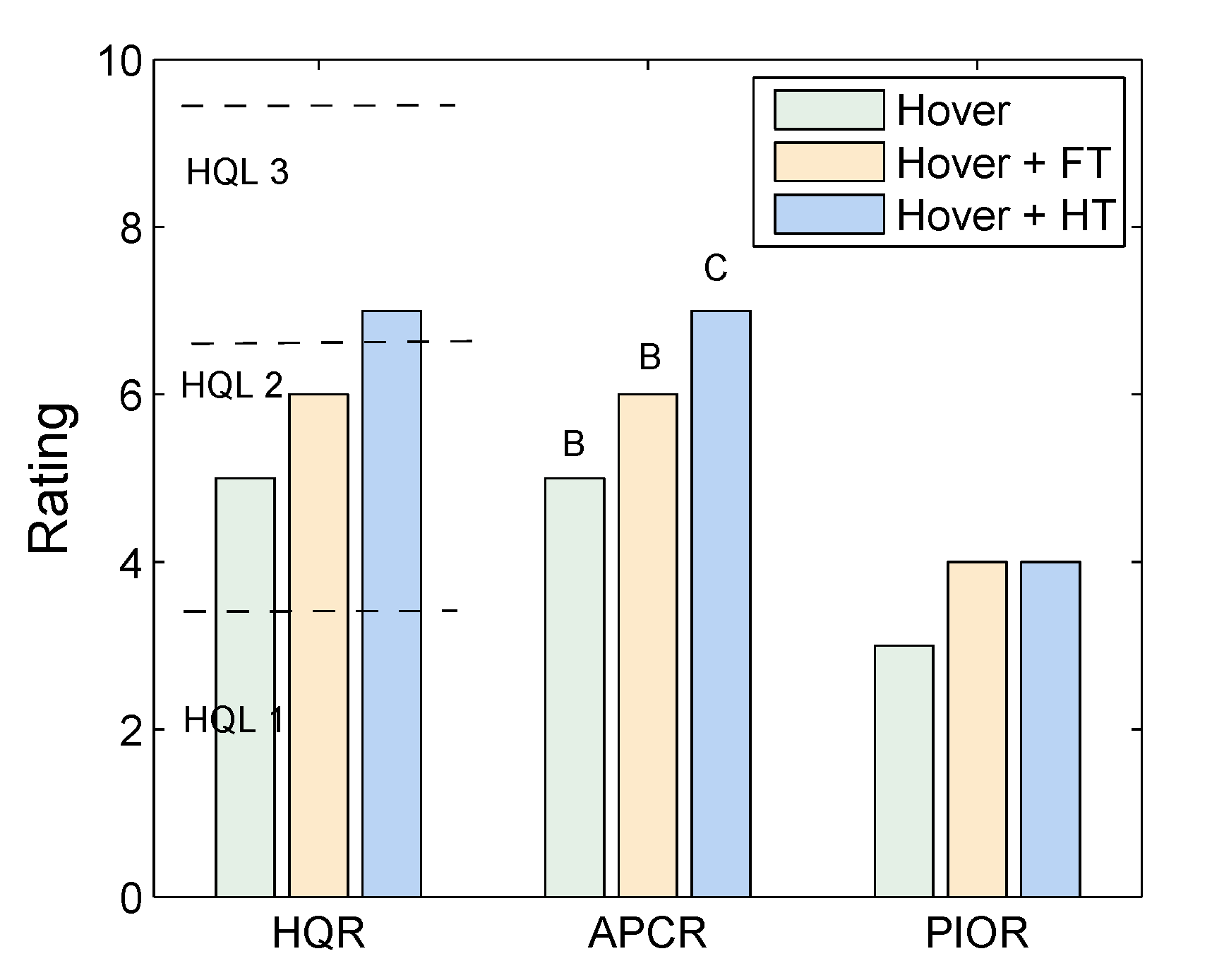
Subjective results are shown in Figure 21 with respect to task. The influence of the task performance parameter modification is shown through changes to the ratings. By increasing the hover translation speed, the HQR increases from HQR = 5 to HQR = 6. The reduction of tolerances during the hover element increased the HQR from HQR = 5 to HQR = 7. This is a reduction in HQ Level. The tightened tolerances during the hover element also changed the severity and nature of oscillations. Using the ADS-33 guidelines, oscillations were classified as moderate and convergent. After the modifications, the pilot stated that oscillations were severe and sustained during the completion of the manoeuvre.

5. Discussion

During the test campaign, the first in-flight evaluations using the APC scale were performed. Valuable pilot feedback was collected on the applicability and utility of the scale during PIO investigations. During the test campaign, only the evaluation pilot assigned ratings using the scale. However, during briefing and debriefing, the safety pilot provided additional comments and suggestions.
Generally, both pilots were in agreement that the APC scale solves a number of issues concerning the legacy PIO scale. In this investigation, both scales were used to allow direct comparison. The legacy scale in tabulated form eliminates some of the known problems relating to the use of the subjective decision tree [29]. However, using the tabulated scale, the pilots must award a rating based upon the closest subjective description to the observed PIO. Inevitably, there elements of ambiguity, and not all cases feature all characteristics described in the rating. It is often the case that an observed PIO can fit into the description within 2–3 ratings (of which there are only 6), meaning that the variation can be high across several test pilots, leading to poor data quality and poor reliability. The addition of the decision tree to the legacy scale (not used in this investigation) provides the opposite consequences, whereby the pilots are forced to assign at rating, regardless of the perceived severity. Unlike the Cooper–Harper scale, the pilot does not have any option to subjective award the final rating. The APC scale solves this problem using a decision tree format followed by pilot subjective opinion. The intention is to allow for pilots to use their experience and knowledge to provide assessment, but to reduce the amount of ratings that the pilots may assign. As the questions are based on performance and factual observations, the subjective opinion is minimised, resulting in a decreased variation across several pilots when compared to the legacy rating scale.
The scale also brings focus to the mission task requirements, highlighting the fact that the rating is dependent on these requirements and not a general assessment. Mission task requirements are not prominent in the legacy scale, and the ability of the pilot to adequately perform requirements is not used as a factor in the assessment. The severity of a PIO is directly related to the task that is being flown (and the pilot feedback gain required for the task). The APC rating reflects the ability of the pilot to complete/abandon an MTE and the performance standards achieved. For this reason, it is clear that any assigned APC rating is only applicable when associated with a specific MTE course description and performance standards. This reduces the ambiguity of the assigned rating, providing a clear indication of the situation where PIO incipient conditions are experienced.
Despite favouring the APC scale, pilots did provide suggestions for modifications, particularly concerning the phrasing and wording included. Firstly, pilots were not completely in agreement as to the meaning of the term ‘adaptation’. They expressed that this should be included with the scale. Adaptation is defined as the degree to which the pilot is required to modify their behaviour and strategy. As contained in Ref. [21];
“If the pilot need not apply any changes to their control or task strategy, this represents negligible adaptation (i.e., they do not need to respond to oscillations). Considerable pilot adaptation refers to the situations where the pilot must consciously act to suppress the oscillations, but may have spare capacity to complete some other tasks.”
One of the pilots commented that the jump from negligible to considerable pilot adaptation is large. In the Cooper–Harper HQR scale, gradual increments are made using the terms minimal, moderate, considerable, extensive. The terms should be compared with those used in the APC scale. The pilot questioned whether using the same terminology contained in the HQR scale could provide a benefit, providing standardisation of terms.
Similarly, the pilot also questioned the best way to interpret the additional letter terms. These terms are intended to characterise the oscillations. In particular, what should be pilot state when oscillation have changed due to the pilot adaptation. For example, without adaptation, divergent oscillations occur which become sporadic following a change in control strategy. The way in which the rating should be applied is ambiguous. It is the intention that the oscillations experienced prior to adaptation should be provided as feedback. Clearer guidance regarding this point will be used when performing further investigations with the APC scale.
During the investigations, MTEs were taken directly from ADS-33. These were selected as they have well known accepted performance requirements, deemed to reflect those requirements for current operational rotorcraft. The standards are accepted worldwide and used to determine whether vehicles exhibit deficiencies or carefree handling. Some of the ADS-33 task performance requirements also include additional statements regarding undesirable oscillations (i.e., desired performance for the hover manoeuvre).
Whilst the manoeuvres are standardised, the requirements reflect typical expected performance. PIOs often occur following unexpected conditions, often forced by the trigger situation. In order to simulate performance closer to the operational limits of the vehicle, task performance requirements of the hover manoeuvre were modified. These modifications were considered to still reflect operational requirements for utility rotorcraft. Pilots considered that the increase in translation speed had a minor effect on HQ and PIO ratings. PIOs when identified had a convergent nature, often suppressed following a short period. During the completion of the task with increased translational speed, performance must be carefully observed to ensure that pilots to do commence the deceleration early to avoid exposing oscillations.
Decreasing longitudinal and lateral performance tolerances had a greater effect than changing the translation speed. The change forced the pilot to increase the feedback gain throughout the hover section and maintenance. As the modification to the task was applied to the maintenance phase, it had a longer term effect and hence produced more sustained PIOs.
As previously stated, the APCRs awarded when using the scale are dependent upon the task performance requirements. When performing tasks as contained in ADS-33 to observe HQ deficiencies, it is acceptable for the pilot to aim to achieve adequate performance tolerances when they are unable to obtain desired performance. This must be demonstrated before the pilot is permitted to fly the task to achieve only adequate performance tolerances. The practice is necessary when awarding HQRs. Regarding PIOs, this has the potential to suppress oscillations and subsequently impacts the APC rating obtained. Therefore, when performing tests to expose PIOs, the following should be observed;
“Desired and adequate performance standards are required to ensure that the vehicle is flown to known requirements. The pilot should always attempt to achieve desired performance standards, even if these cannot be attained.”

6. Conclusions

This paper presents results obtained from a joint test campaign conducted by researchers from NRC Canada and DLR. The work is part of an ongoing collaboration between the organisations. Flight tests were conducted to test and validate methods to assess subjectively and objectively the incipience and severity of aircraft/rotorcraft pilot coupling (A/RPC) events. Specifically during these tests, pilot-induced oscillations (PIOs) were of interests. The flights were conducted in March 2019 using the Bell 205 experimental helicopter, operated and maintained by the NRC. The following are the key conclusions from this research effort;
  • The boundaries developed for use with PAC from simulation campaigns were found to be suitable for in-flight investigations. Results obtained validated boundaries previously developed from simulation campaigns only. This was shown for a range of vehicle control configurations. Correlation was found for both cases where no PIO and PIO were experienced. For this reason, the boundaries are considered suitable for in-flight investigations.
  • The adverse pilot coupling (APC) scale was used for the first time during in-flight investigations. The scale was found to successfully solve limitations found with the legacy PIO scale. Pilots, however, commented that further improvements to the APC scale could be beneficial to further improve its utility.
  • Four mission task elements (MTEs) from ADS-33E were employed. From these manoeuvres, the Pirouette was found to be the most suitable to expose PIOs. During the attempted completion of the task, severe and sustained PIOs were experienced. Both the hover and lateral reposition manoeuvres were found to be suitable to expose PIOs. The Depart–Abort was considered less successful, due to the performance parameters associated with the manoeuvre.
  • The hover MTE was modified to improve its suitability to expose PIOs. The standard manoeuvre is considered to be low aggression. Two modifications were made to the task; an increase in transition speed and a reduction in allowable hover tolerances. The latter modification was found to expose larger and more sustained PIOs.
The study described in the paper was limited due to available flying hours. In the future, it is recommended that further and more detailed tests be conducted to modify the ADS-33 MTEs to improve their suitability to expose RPCs. Furthermore, as previously discussed, pilots commented that modifications to the APC scale could be beneficial. This will be investigated in future research. In this work, only simplistic PIO ‘triggers’ were used (i.e., time delays), as the focus was on tool and technique development. Further research should focus on testing of dynamic PIO ‘triggers’, such as mode switching and failures. Some recent research efforts have been conducted using simulation [30] and it is planned to continue this research through further in-flight testing.

Author Contributions

Formal analysis, M.J., M.A. and A.G.; funding acquisition, M.H.; investigation, M.J., M.A., M.H., M.B. and P.C.; methodology, M.J., M.H. and M.B.; project administration, M.J. and M.H.; software, M.J.; writing—original draft, M.J.; writing—review and editing, M.J., M.A., M.H., M.B., P.C. and A.G. All authors have read and agreed to the published version of the manuscript.

Funding

This research received no external funding.

Acknowledgments

The authors wish to thank Maximilian Schubert, who was responsible for the real-time data connection between the helicopter data output and the phase-aggression criterion software. Thanks is extended to all who assisted with the flight test preparation.

Conflicts of Interest

The authors declare no conflict of interest.

Abbreviations

The following abbreviations are used in this manuscript:
ACAttitude Command Attitude Hold
ADSAeronautical Design Standard
APC(R)Adverse pilot coupling (Rating)
A/RPCAircraft/rotorcraft pilot coupling
ARISTOTELAircraft and Rotorcraft Pilot Couplings: Tools and Techniques for Alleviation and Detection
CVACommand Validation Algorithm
DLRDeutsches Zentrum fuer Luft und Raumfahrt (German Aerospace Center)
FBWFly-by-wire
FTFast transition
HTHalf tolerances
HQ(R)Handling Qualities (Rating)
MTEMission task element
NRCNational Research Center Canada
PACPhase-aggression criterion
PAOPilot-assisted oscillation
PIO(R)Pilot-induced oscillation (Rating)
PIWPilot-inceptor workload
RDRate Damped
RDHRate Damped High
RDLRate Damped Low
UCEUsable cueing environment

Appendix A

P = Pirouette H = Hover D = Depart–Abort L = Lateral reposition HT = Half tolerances FT = Fast transition 150, 300 = Time Delay, ms
Table A1. Day 1: 4th March 2019, Aircraft Bell 205A, C-FYZV.
RunConfigurationMHQRAPCRPIORComments
13–15B205-RDP55A3UCE 1, high frequency pitch PIO/PAO caused by loose hand grip and vibration of aircraft.
24–25B205-RDP45D2Classical low frequency PIO in lateral axis, longitudinal control B205-RDH.
30–35B205-RDHP422n/a
47–52B205-RDLP67C4Tripped out several times. Finally attempted manoeuvre and completed with only half a turn in 30 s, due to trips associated gusts.
65–67B205-ACP---Pirouette not possible due to system trips.
68–72B205-RDH54A2UCE 1, oscillations caused undesirable oscillations with PIO in multiple axes.
73, 74B205-RDD422Minor lateral disturbances. Low pilot gain required due to relaxed tolerances to complete manoeuvre to desired standards.
75–77B205-RDL44A2Cross wind a factor-exposed more lateral oscillations that the hover in wind during the depart abort.
Table A2. Day 2: 5th March 2019, Aircraft Bell 205A, C-FYZV.
RunConfigurationMHQRAPCRPIORComments
15–17, 24B205-RDHH411First case difficult due to the poor horizontal VCR (2), fore-aft stabilization requires significant pilot concentration. Pilot needs to look at the cones more regularly, instead of using peripheral cues. Subsequent attempts (24) completed after making markings in the snow.
18–23B205-RDLH54B2PIO felt in yaw axis / fore aft axis
25–30B205-ACH44B (yaw) 2 (pitch)2Achieving the hover element of the task was an issue, workload reduces during the hover. Small oscillations not a major problem. Yaw oscillations apparent.
31–35B205-ACP411All attempts except last were aborted due to CVA trips. Due to controller and not PIOs.
36–40B205-RDHL44A2First event poorer UCE (Att. 1, Horz. 3, Vert. 2, UCE 1). Al subsequent attempts made after marking snow. Throughout attempts pilot was gradually increasing the aggression to accelerate.
41–43B205-RDLL44B2PIO in lateral mainly during the acceleration and deceleration.
44–48B205-ACL---Task abandoned due to multiple CVA trips.
54B205-RD + 150 msH55C3Longitudinal and lateral axis oscillations at the same frequencies.
55–57B205-RD + 300 msH87D4Struggled to maintain adequate. Multi-axis aggravated yaw
58, 59B205-RD + FTH411Hover with 13–17 kts.
60–64B205-RDH + 150 ms + FTH66B48 s to stabilise.
65B205-RDH + 150 msH55B3PIO in yaw, possibly roll and pitch.
67, 71B205-RDH + HTH55B3Cyclic movement predominantly in pitch axis but with some lateral. Half tolerances in height, horizontal position but standard heading.
72B205-RDH + 150 ms + HTH77C4Striving for the desired tolerance drove up the feedback gain and caused a PIO. If the pilot had accepted the adequate tolerances, the gain would have probably been lower and so the PIO would probably not have developed so aggressively. Half tolerances in height and horizontal position, standard heading.

References

  1. Pavel, M.; Jump, M.; Dang-Vu, B.; Masarati, P.; Gennaretti, M.; Ionita, A.; Zaichik, L.; Smaili, H.; Quaranta, G.; Yilmaz, D.; et al. Adverse Rotorcraft Pilot Couplings-Past, Present and Future Challenges. Prog. Aerosp. Sci. 2013, 62, 1–51. [Google Scholar] [CrossRef]
  2. Klyde, D.H.; Mitchell, D.G. Investigating the Role of Rate Limiting in Pilot-Induced Oscillations. AIAA J. Guid. Control. Dyn. 2004, 27, 804–813. [Google Scholar] [CrossRef]
  3. McRuer, D.T.; Droste, C.S.; Hansman, R.J.; Hess, R.A.; LeMaster, D.P.; Matthews, S.; McDonnell, J.D.; McWha, J.; Melvin, W.W.; Pew, R.W. Aviation Safety and Pilot Control: Understanding and Preventing Unfavorable Pilot-Vehicle Interactions; National Research Council: Washington, DC, USA, 1997. [Google Scholar]
  4. Muscarello, V.; Quaranta, G.; Masarati, P.; Lu, L.; Jones, M.; Jump, M. Prediction and Simulator Verification of Roll/Lateral Adverse Aeroservoelastic Rotorcraft-Pilot Couplings. AIAA J. Guid. Control. Dyn. 2016, 39, 42–60. [Google Scholar] [CrossRef] [Green Version]
  5. Walden, B. A Retrospective Survey of Pilot-Structural Coupling Instabilities in Naval Rotorcraft. In Proceedings of the 63rd American Helicopter Society Annual Forum, Virginia Beach, VA, USA, 1–3 May 2007. [Google Scholar]
  6. National Transportation Safety Board (NTSB). Aviation Accident Data Summary: Accident Number DCA16FA199; National Transportation Safety Board (NTSB): Washington, DC, USA, 2018. [Google Scholar]
  7. Agenzia Nazionale per la Sicurezza del Volo (ANSV). Final Report: Accident Occurred to the AgustaWestland AW609 Aircraft Registration Marks N609AG; Agenzia Nazionale per la Sicurezza del Volo (ANSV): Rome, Italy, 2017. [Google Scholar]
  8. McRuer, D.; Jex, H. A Review of Quasi-Linear Pilot Models. IEEE Trans. Hum. Factors Electron. 1967, HFE-8, 231–249. [Google Scholar] [CrossRef] [Green Version]
  9. Serafini, J.; Greco, L.; Gennaretti, M. Rotorcraft-Pilot Coupling Analysis through State-Space Aerodynamic Modelling. Aeronaut. J. 2015, 119, 1105–1122. [Google Scholar] [CrossRef] [Green Version]
  10. Masarati, P.; Quaranta, G.; Lu, L.; Jump, M. A Closed Loop Experiment of Collective Bounce Aeroelastic Rotorcraft-Pilot Coupling. J. Sound Vib. 2014, 333, 307–325. [Google Scholar] [CrossRef]
  11. Masarati, P.; Quaranta, G.; Zanoni, A. A Detailed Biomechanical Pilot Model for Multi-Axis Involuntary Rotorcraft-Pilot Couplings. In Proceedings of the 41st European Rotorcraft Forum, Munich, Germany, 1–4 September 2015. [Google Scholar]
  12. Yilmaz, D.; Pavel, M.; Jones, M.; Jump, M.; Lu, L. Identification of Pilot Control Behavior During Possible Rotorcraft Pilot Coupling Events. In Proceedings of the 38th European Rotorcraft Forum, Amsterdam, The Netherlands, 4–7 September 2012. [Google Scholar]
  13. Lu, L.; Jump, M. Multiloop Pilot Model for Boundary-Triggered Pilot-Induced Oscillation Investigations. AIAA J. Guid. Control. Dyn. 2014, 37, 1863–1879. [Google Scholar] [CrossRef]
  14. Jones, M. The Use of the Open-Loop Onset Point (OLOP) to Predict Rotorcraft Pilot-Induced Oscillations. CEAS Aeronaut. J. 2020, 11, 693–711. [Google Scholar] [CrossRef] [Green Version]
  15. Cameron, N.; Cunliffe, C.; White, M.; Klyde, D.; de Mello, R. Further Assessment of a Scalogram Based PIO Metric Using University of Liverpool Tilt-Rotor Simulation Data. In Proceedings of the AIAA Scitech Atmospheric Flight Mechanics Conference, Kissimmee, FL, USA, 8–12 January 2018. [Google Scholar]
  16. Pavel, M.; Masarati, P.; Gennaretti, M.; Jump, M.; Zaichik, L.; Dang-Vu, B.; Lu, L.; Yilmaz, D.; Quaranta, G.; Ionita, A.; et al. Practices to Identify and Preclude Adverse Aircraft-and-Rotorcraft-Pilot Couplings—A Design Perspective. Prog. Aerosp. Sci. 2015, 76, 55–89. [Google Scholar] [CrossRef] [Green Version]
  17. Yilmaz, D.; Pavel, M.; Dang-Vu, B.; Jones, M.; Jump, M.; Lu, L. PIO Susceptibility Accompanying HQ Prospects in Preliminary Rotorcraft Design. In Proceedings of the 39th European Rotorcraft Forum, Moscow, Russia, 3–6 September 2013. [Google Scholar]
  18. Pavel, M.; Dang Vu, B.; Götz, J.; Jump, M.; Dieterich, O. Adverse Rotorcraft-Pilot Couplings-Prediction and Suppression of Rigid Body RPCs: Sketches from the Work of GARTEUR HC-AG16. In Proceedings of the 34th European Rotorcraft Forum, Liverpool, UK, 16–19 September 2008. [Google Scholar]
  19. Jones, M. Prediction, Detection, and Observation of Rotorcraft Pilot Couplings. Ph.D. Thesis, University of Liverpool, Liverpool, UK, 2014. [Google Scholar]
  20. Dieterich, O.; Goetz, J.; Dang Vu, B.; Haverdings, H.; Masarati, P.; Pavel, M.; Jump, M.; Gennaretti, M. Adverse Rotorcraft-Pilot Couplings: Recent Research Activities in Europe. In Proceedings of the 34th European Rotorcraft Forum, Liverpool, UK, 16–19 September 2008. [Google Scholar]
  21. Jones, M.; Jump, M. New Methods to Subjectively and Objectively Evaluate Adverse Pilot Couplings. J. Am. Helicopter Soc. 2015, 60, 1–13. [Google Scholar] [CrossRef]
  22. Jones, M.; Jump, M.; Lu, L.; Yilmaz, D.; Pavel, M.; Masarati, P.; Quaranta, G.; Muscarello, V. Exposing Rotorcraft Pilot Couplings using Flight Simulation. In Proceedings of the 39th European Rotorcraft Forum, Moscow, Russia, 3–6 September 2013. [Google Scholar]
  23. United States Army Aviation and Missile Command. Aeronautical Design Standard Performance Specification Handling Qualities Requirements for Military Rotorcraft, ADS-33E-PRF; United States Army Aviation and Missile Command: Redstone Arsenal, AL, USA, 2000. [Google Scholar]
  24. Alexander, M.; Hoefinger, M. Survey of Variable Stability Helicopter Applications in Handling Qualities Research. In Proceedings of the 69th American Helicopter Society Annual Forum, Phoenix, AZ, USA, 21–23 May 2013. [Google Scholar]
  25. Gray, W.R. Handling Qualities Evalaution at the USAF Test Pilot School. In Proceedings of the AIAA Atmospheric Flight Mechanics Conference, Chicago, IL, USA, 10–13 August 2009. [Google Scholar]
  26. DiFranco, D.A. Flight Investigation of Longitudinal Short Period Frequency Requirements and PIO Tendencies; Tech. Rep. AFFDL-TR-66-163; Cornell Aeronautical Lab: Buffalo, NY, USA, 1967. [Google Scholar]
  27. Weingarten, N.; Chalk, C.R. In-Flight Investigation of Large Airplane Flying Qualities for Approach and Landing; Tech. Rep. AFWAL-TR-81-3118; Calspan: Buffalo, NY, USA, 1981. [Google Scholar]
  28. Pavel, M.D.; Malecki, J.; Dangvu, B.; Masarati, P.; Gennaretti, M.; Jump, M.; Jones, M.; Smaili, H.; Ionita, A.; Zaichek, L. Present and Future Trends in Rotorcraft Pilot Couplings (RPCs)—A Retrospective Survey of Recent Research Activites Within the European Project ARISTOTEL. In Proceedings of the 37th European Rotorcraft Forum, Gallarate, Italy, 13–15 September 2011. [Google Scholar]
  29. Mitchell, D. Flight and Ground Testing for Pilot-Induced Oscillations. In Proceedings of the IEEE Aerospace Applications Conference, Snowmass at Aspen, CO, USA, 6–13 March 1999. [Google Scholar]
  30. Jones, M.; Barnett, M. Active Inceptor Failure as a Trigger for Pilot-Induced Oscillations. J. Am. Helicopter Soc. 2020, 65, 1–14. [Google Scholar] [CrossRef]
Figure 1. NRC Bell 205 airbourne simulator.
Aerospace 07 00136 g001
Figure 2. NRC Bell 205 basic simplified control structure.
Aerospace 07 00136 g002
Figure 3. NRC Bell 205 calculated bandwidth plotted against ‘All Other mission task element (MTE)’ boundaries, (a) roll axis; (b) pitch axis.
Aerospace 07 00136 g003
Figure 4. On-board view of elements of ADS-33 Hover test course used for evaluations.
Aerospace 07 00136 g004
Figure 5. ADS-33 test course located at National Research Council (NRC), Ottawa.
Aerospace 07 00136 g005
Figure 6. Schematic of phase-aggression criterion (PAC) detection algorithm.
Aerospace 07 00136 g006
Figure 7. Calculation of last oscillation cycle and phase.
Aerospace 07 00136 g007
Figure 8. Adverse pilot coupling (APC) Scale.
Aerospace 07 00136 g008
Figure 9. Case 24-lateral axis-APC = 5D, (a) time recording; (b) PAC results.
Aerospace 07 00136 g009
Figure 10. Case 24-longitudinal axis, (a) time recording; (b) PAC results.
Aerospace 07 00136 g010
Figure 11. Comparison of example No PIO and severe PIO cases. (a) Comparison of time responses; (b) PAC results for Case 35, lateral, No PIO; (c) PAC results for Case 48, lateral, severe PIO.
Aerospace 07 00136 g011
Figure 12. Comparison ground position during the completion of the Pirouette manoeuvre.
Aerospace 07 00136 g012
Figure 13. APC ratings obtained from the Pirouette MTE w.r.t. roll bandwidth.
Aerospace 07 00136 g013
Figure 14. Comparison between PAC results for Rate Damped High (RDH) and Rate Damped Low (RDL) configurations recorded during the completion of the hover manoeuvre. (a) Day 2-Case 24-RDH-long; (b) Day 2-Case 23-RDL-long; (c) Day 2-Case 24-RDH-lat; (d) Day 2-Case 23-RDL-lat.
Aerospace 07 00136 g014
Figure 15. Results from lateral reposition, Case 77-Day 1-APC = 4A. (a) Time recording; (b) PAC results.
Aerospace 07 00136 g015
Figure 16. Results from lateral reposition-Case 41, Day 2-APC = 4B. (a) Time recording; (b) PAC results.
Aerospace 07 00136 g016
Figure 17. Results from Depart–Abort, longitudinal, Case 73 APC = 2. (a) Time recording-Case 73; (b) PAC results for Case 73.
Aerospace 07 00136 g017
Figure 18. Average PAC parameters obtained during completion of manoeuvres, Day 1.
Aerospace 07 00136 g018
Figure 19. Comparison of results obtained from three hover manoeuvres.
Aerospace 07 00136 g019
Figure 20. Pitch and roll axis oscillatory response, hover, 30 s stabilization period.
Aerospace 07 00136 g020
Figure 21. Comparison of results obtained from three hover manoeuvres completed using the same configuration.
Aerospace 07 00136 g021
Table 1. Trial mission tasks and criteria, taken from [23].
TaskCriteriaDesiredAdequate
Precision HoverHeading±5 ±10
Time (Decel., Hover)5 s8 s
Lateral RepositionAltitude±10 ft±15 ft
Heading± 10 ±15
Longitudinal track±10±20
Time (Complete)18 s22 s
PirouetteAltitude±3 ft±10 ft
Heading±10 ±15
Time (Complete)45 s60 s
Time (Hover)5 s10 s
Depart AbortAltitude<50 ft<75 ft
Heading±10 ±15
Time (Complete)25 s30 s
Rotor Speed97–100%91–97%
Table 2. Useable cueing environment (UCE) evaluation results.
TaskAttitudeTranslationalVerticalOverall
Pirouette (Day 1)1221
Pirouette (Day 2)1111
Hover (Day 1)1221
Hover (Day 2)1111
Lateral Reposition (Day 1)1211
Lateral Reposition (Day 2)1221
Depart/Abort (Day 1)1111
Table 3. Pilot-Induced Oscillation (PIO) Rating Scale. Reproduced from [26].
DescriptionRating
No tendency for pilot to induce undesirable motions.1
Undesirable motions tend to occur when the pilot initiates abrupt manoeuvres or attempts tight control. These motions can be prevented or eliminated but only at the sacrifice to task performance or through considerable pilot attention and effort.2
Undesirable motions easily induced when pilot initiates abrupt manoeuvres or attempts tight control. These motions can be prevented or eliminated but only at the sacrifice to task performance or through considerable pilot attention and effort.3
Oscillations tend to develop when the pilot initiates abrupt manoeuvres or attempts tight control. Pilot must open loop by releasing or freezing the stick.4
Divergent oscillations tend to develop when the pilot initiates abrupt manoeuvres or attempts tight control. Pilot must open loop by releasing or freezing the stick.5
Disturbance or normal pilot control may cause divergent oscillations. Pilot must open control loop by releasing or freezing the control stick.6
Table 4. Extracted values of H s from step inputs.
Configuration H s , lat (deg/s/deg) H s , Long (deg/s/deg)
B205-RD13.011.0
B205-RDL22.012.0
B205-RDH7.106.00
Table 5. Handling Qualities Ratings (HQRs) awarded.
TaskPirouetteHoverLat. Rep.Dep. Abort
B205-RD5; 4544
B205-RDL654n/a
B205-RDH444n/a
B205-AC44n/an/a
Table 6. APCRs awarded.
TaskPirouetteHoverLat. Rep.Dep. Abort
B205-RD5A; 5D4A4A2
B205-RDL7C4B4Bn/a
B205-RDH214An/a
B205-AC14Bn/an/a
Table 7. PIORs awarded.
TaskPirouetteHoverLat. Rep.Dep. Abort
B205-RD3; 2222
B205-RDL422n/a
B205-RDH212n/a
B205-AC12n/an/a
Table 8. Summary of PAC PIO detection w.r.t. pilot ratings.
PACPirouetteHoverDep. AbortLat. Rep.
No2 (roll)1n/a4A (both)
Mod.5A (roll)4A (both)2 (roll)4A, 4B (roll)
Sev.7C (roll)4B (roll)n/an/a
Table 9. Comparison between PAC detections and pilot subjective ratings.
Subjective APC Rating
No PIOPIO
Objective PACNo PIO2 (x)1 (w)
PIO1 (y)6 (z)

