Article

Numerical and Experimental Investigation of the Design of a Piezoelectric De-Icing System for Small Rotorcraft Part 2/3: Investigation of Transient Vibration during Frequency Sweeps and Optimal Piezoelectric Actuator Excitation

1
Anti-icing Materials International Laboratory (AMIL), Université du Québec à Chicoutimi (UQAC), Chicoutimi, QC G7H 2B1, Canada
2
National Research Council Canada, Flight Research Laboratory, Ottawa, ON K1A 0R6, Canada
*
Author to whom correspondence should be addressed.
Aerospace 2020, 7(5), 49; https://doi.org/10.3390/aerospace7050049
Submission received: 31 March 2020 / Revised: 21 April 2020 / Accepted: 24 April 2020 / Published: 28 April 2020
(This article belongs to the Special Issue Deicing and Anti-Icing of Aircraft)

Abstract

:
The objective of this research project is divided in four parts: (1) to design a piezoelectric actuator based de-icing system integrated to a flat plate experimental setup, develop a numerical model of the system and validate experimentally; (2) use the experimental setup to investigate actuator activation with frequency sweeps and transient vibration analysis; (3) add an ice layer to the numerical model, predict numerically stresses at ice breaking and validate experimentally; and (4) implement the concept to a blade structure for wind tunnel testing. This paper presents the second objective of this study, in which the experimental setup designed in the first phase of the project is used to study transient vibration occurring during frequency sweeps. Acceleration during different frequency sweeps was measured with an accelerometer on the flat plate setup. The results obtained showed that the vibration pattern was the same for the different sweep rate (in Hz/s) tested for a same sweep range. However, the amplitude of each resonant mode increased with a sweep rate decrease. Investigation of frequency sweeps performed around different resonant modes showed that as the frequency sweep rate tends towards zero, the amplitude of the mode tends toward the steady-state excitation amplitude value. Since no other transient effects were observed, this signifies that steady-state activation is the optimal excitation for a resonant mode. To validate this hypothesis, the flat plate was installed in a cold room where ice layers were accumulated. Frequency sweeps at high voltage were performed and a camera was used to record multiple pictures per second to determine the frequencies where breaking of the ice occur. Consequently, the resonant frequencies were determined from the transfer functions measured with the accelerometer versus the signal of excitation. Additional tests were performed in steady-state activation at those frequencies and the same breaking of the ice layer was obtained, resulting in the first ice breaking obtained in steady-state activation conditions as part of this research project. These results confirmed the conclusions obtained following the transient vibration investigation, but also demonstrated the drawbacks of steady-state activation, namely identifying resonant modes susceptible of creating ice breaking and locating with precision the frequencies of the modes, which change as the ice accumulates on the structure. Results also show that frequency sweeps, if designed properly, can be used as substitute to steady-state activation for the same results.

Graphical Abstract

1. Introduction

As a solution to in flight icing problematics, the current project investigates the use of piezoelectric actuators as a low-energy de-icing system that could be implemented on small rotorcraft. The ice accumulation during flight leads to a decrease in lift and an increase in drag, torque, vibration and imbalance. All helicopters currently habilitated to fly into icing conditions are equipped with an electrothermal ice protection system for the main rotor and those systems are not suitable for small rotorcraft due to their excess power requirements and the associated additional weight [1]. Rotorcraft are often used for their great flexibility and easy access to inaccessible terrain environments and the community is in dire need of finding an alternative for small rotorcraft and is in active research to develop and integrate it. The first phase of this research project investigated numerically the design of an experimental setup as well as the development of the numerical model of the final design and the experimental validation of the model [2].
In this paper, the amplitude of transient vibrations obtained during frequency sweeps is investigated and compared to steady-state activation case to determine optimal actuator excitation for de-icing. In a previous project, Harvey [3] followed by Villeneuve and al. [4] showed a proof of concept for de-icing with actuator patches using frequency sweeps. They succeeded in total or partial de-icing for flat plates, a thinned Bell 206 main rotor and a Bell 206 tail rotor blade. Sweeping through different frequency range for different duration has proven efficient, but de-icing using fixed frequencies was not successful. No explanation was found to elucidate these findings. It was thought that transient phenomena, like mode superposition or other, could improve the de-icing efficiency. Also, the frequency range and duration for the frequency sweeps used for de-icing were obtained mostly on trial and error and no guidelines were available or obtained to help with the determination of an optimal excitation. None of the study found in the literature on vibration based de-icing investigated transient effect occurring during frequency sweeps, either experimentally nor numerically. Forsyth and Warburton [5] have accurately predicted the transient response with the Rayleigh method of cantilever plates to impulse load. Investigation of the transient vibration of a completely free plate has been done by Mochida and Ilanko [6]. They showed that the superposition method can be used to calculate the transient response of completely free plates with their natural frequencies and modes. They also demonstrated that transient response is dominated by the lower modes. Rock and Hinton [7] used the finite element method to calculate the transient response of simply supported thin and thick plates. Wu and al. [8] and followed by Kim and Lee [9] have successfully studied the transient responses of thin plates to moving forces. Those studies have focused on the transient response to either impulse load or moving loads at fixed frequencies.
This paper is divided in two main sections. The first section describes the experimental setup used to investigate the structure’s vibration response to sine sweeps to understand phenomena involved and determine how they impact de-icing processes. For a thorough characterization of the experimental setup, the amplitude ratio for different sweep rates was comprehensively studied. In this study, frequency sweeps were obtained by linearly increasing in time the frequency of excitation of the piezoelectric actuators during a single test within a frequency range of interest. Different frequency ranges and frequency sweep durations were tested which resulted in different frequency sweep rates. This resulted in a transient excitation of the system, as opposed to steady-state excitation in which the system was excited at a constant frequency and constant magnitude. The results obtained were used to define the optimal excitation, which in this context corresponds to maximum vibration and mode deployment of the structure. In the second section, the optimal excitation was validated with de-icing tests on ice layers accumulated on the flat plate. The conclusions of the study on the flat plate will be applicable to a curved blade structure. With its different geometry and significantly curved structure, stress generation and mode shapes will be different, but the basic principles for system excitation obtained in this study will be applicable.

2. Investigation of Frequency Sweeps on Vibration Response of the Flat Plate Structure

2.1. Materials and Methods

The setup used in these experiments was designed in the first part of this research project [2]. In this first study, numerical simulations were performed in order to design a setup optimizing mode excitation. It consisted of a 304 stainless steel flat plate, 1.6 mm thick, with five actuators attached to excite the natural frequencies of the structure. The plate was placed between two massive steel 44 w 50.8 mm (2″) thick blocks to create a Clamped-Clamped-Free-Free (CCFF) boundary conditions. The dimensions of the plate were 500 m (L) × 200 mm (W) (Figure 1). Five Physik Instrumente (PI) P-876.A15 actuator patches were installed on the lower surface of the plate, at the centerline of the plate in the width direction. The patches, which are 61 mm in length by 35 mm wide with a total thickness of 0.8 mm, were positioned, as determined in the first phase of the project [2], at both extremities of the plate, at its center and at 16 cm from each edge (Figure 2).
A miniature single axis piezoelectric accelerometer was installed on one edge of the plate for acceleration measurements (Figure 1). PCB Piezotronics model 352C22 was selected for the broad frequency range, dynamic range, small size and low weight. To drive and monitor the piezoelectric actuator system, an electrical system is required. This system uses an Agilient 33500B waveform generator to provide the electrical signal to the actuators. The driving signal for the actuators was amplified using an Amp-line AL-1000-HF-A amplifier with a range of 50 to 1000 V to generate the required vibration level. Since the operational voltage of the actuators is −250 to 1000 V, an Amp-line AL-100DC power source was used to offset the voltage to allow testing close to the limit of the actuators. By offsetting the voltage to values around 400 or 500 V, an alternative voltage of 1000 to 1250 Vpp could be applied without compromising the integrity of the actuators. The voltage applied to the actuators was measured with a Fluke 105B oscilloscope. To monitor and record the signal from the accelerometer a high sample rate National Instrument PCIe-6346 data acquisition card is used.

2.2. Results

Using frequency sweeps to achieve de-icing on a structure has been proven successful in a previous study [4]. Ice cracking and delamination was only achieved in the past when sweeping through different frequency ranges, while all testing performed at fixed frequency were unsuccessful. The activation of the actuators with frequency sweeps during the de-icing tests performed during the previous studies were mostly based on trial and error. To better understand the phenomena occurring during frequency sweeps and the reasons for the successful de-icing, an investigation of the vibration response of the flat plate structure to frequency sweeps was performed experimentally. Frequency sweeps were performed at 200 Vpp with a single piezoelectric actuator. Those frequency sweeps were performed by linearly increasing in time the excitation frequency of the piezoelectric actuator during a single test to excite a frequency band. A voltage of 200 Vpp was selected to obtain significant mode deployment, based on results obtained in the first paper [2], while observing a safe range from the actuator voltage limit to avoid damage. The sweep range was set from 100 Hz to 2500 Hz, which corresponds to the frequency range where de-icing occurred in a previous study [4]. Five different sweep durations were selected, 1, 2, 3, 5 and 10 s, to measure the effect of the frequency sweep rate on the mode deployment. 
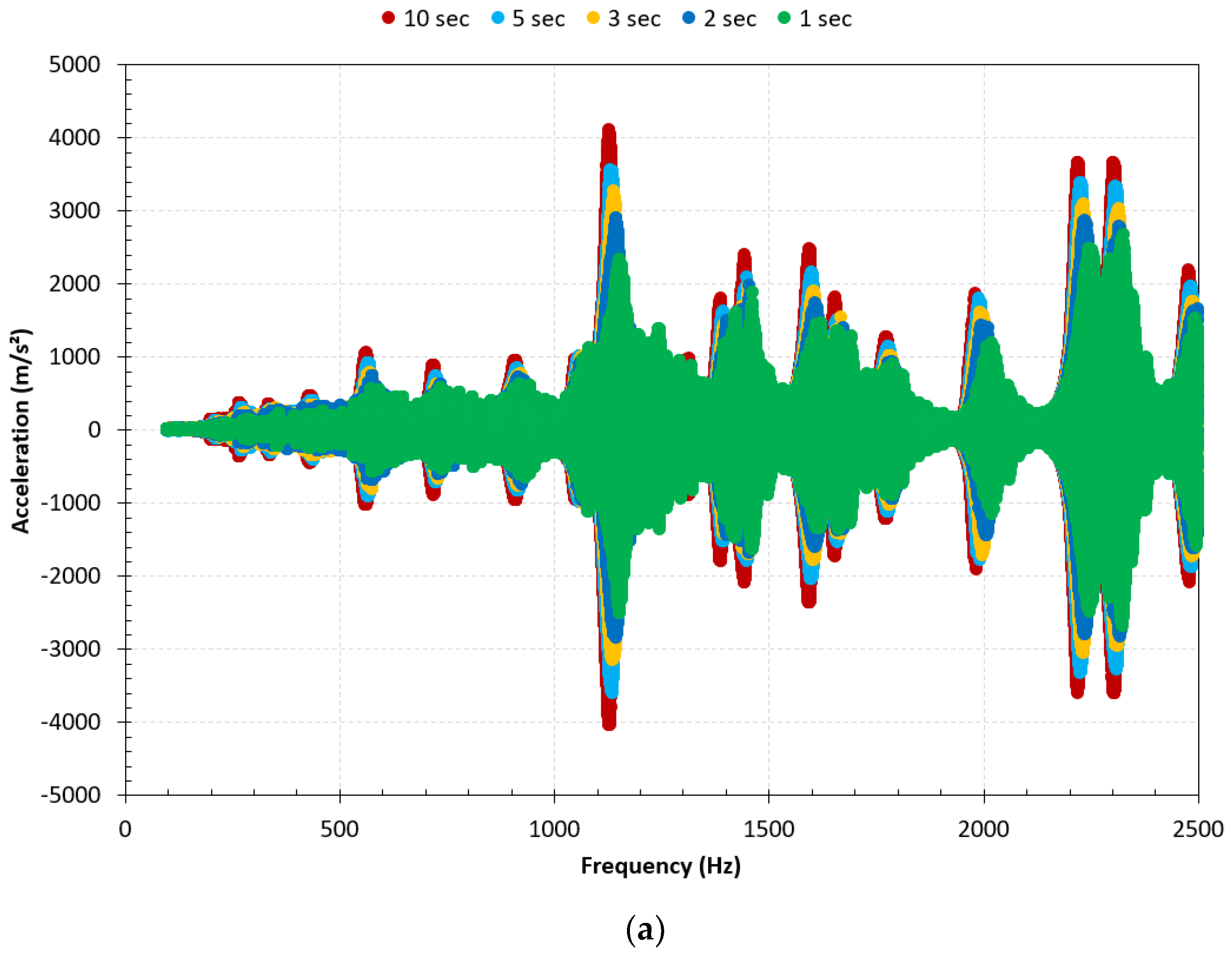
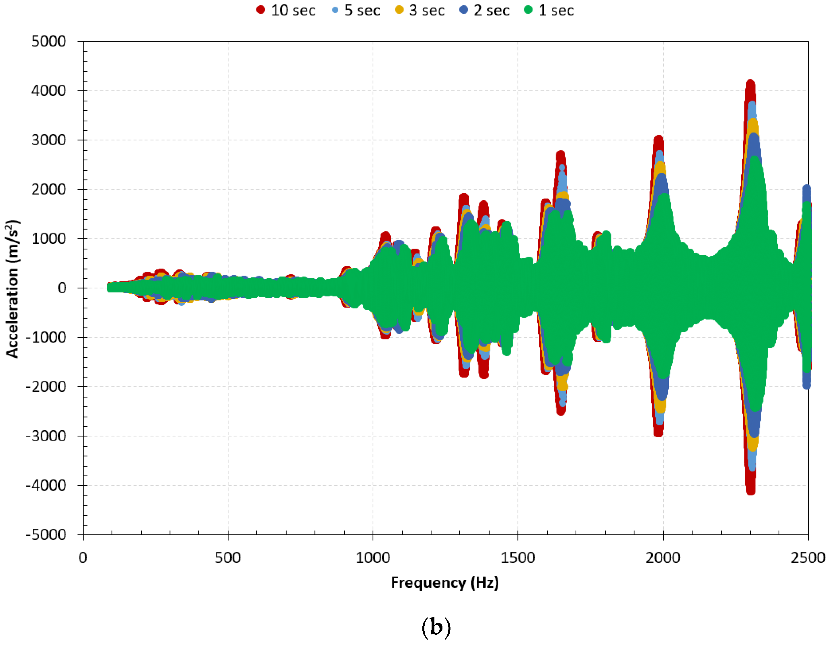
Figure 3 shows the plate acceleration measured on the edge for frequency sweeps with actuators 4 and 5. Due to the position of the actuator 3, only odd resonant modes (with an odd number of anti-nodes) can be properly excited and for this reason it was not used for testing [2].
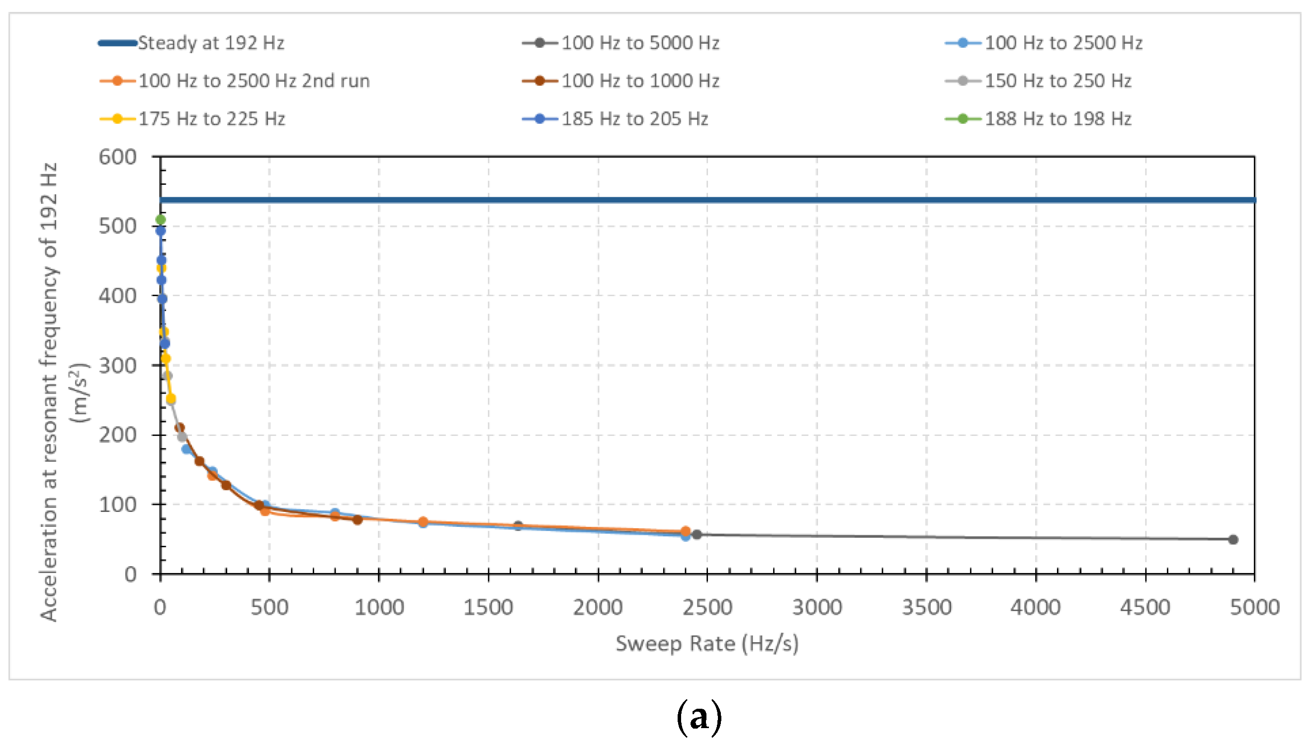
More testing was performed for individual resonant modes. For each of those modes, frequency sweeps were performed for different durations and different frequency ranges. The different frequency ranges were considered to determine if residual vibration of preceding modes during a frequency sweep can impact the acceleration amplitude and deployment obtained for a resonant mode. The resonant frequencies of 192 Hz, 1310 Hz, 1977 Hz and 4669 Hz were therefore selected due to the associated high relative acceleration peaks observed under frequency sweep excitation from 0 to 2500 Hz. The frequency sweeps were performed with piezoelectric actuator 5 and the amplitude of vibration for each sweep is presented in Figure 4 as a function of the sweep rate. The amplitude of vibration obtained in steady-state mode is also shown for each mode.

2.3. Discussion

As is well known, the resonant modes activated by the actuators are easily distinguishable by the distinct peaks of the frequency response function. The two plots in Figure 3 show that the resonant modes are not all activated by each actuator, and some modes have a better deployment (higher peak amplitudes) depending on the actuator activated, which was expected according to the conclusions obtained in the first phase of the project [2].
Moreover, the two plots show that the vibration pattern is similar for all the different sweep durations when excited by the same actuator. The same modes are activated and their amplitude relative to the other modes is similar whether the frequency sweep is performed at a sweep rate of 2400 Hz/s (100 Hz to 2500 Hz in 1 s) or 240 Hz/s (100 Hz to 2500 Hz in 10 s). The acceleration amplitude for each resonant mode increases as frequency sweep rate decrease. For some modes, the amplitude is up to 1.8 times higher when the sweep rate is 240 Hz/s compared to 2400 Hz/s. These results indicate that when sweeping is performed at higher sweeping rates, complete mode deployment is not obtained and acceleration/displacement and stress generation is not optimal for de-icing operations. The vibration pattern being the same for all duration, there is no other transient effect distinguishable, like mode superposition or residual effect from previous activated modes, at those sweeping speed.
The results obtained for tests at individual resonant mode show that as the sweeping rate tends towards zero, acceleration tends toward the steady-state value, which means that there is no benefit in acceleration and displacement brought by transient effect during frequency sweeps from a de-icing perspective where maximum structural acceleration is targeted. This means that maximum mode deployment is obtained at a fixed frequency or when sweep rate tends towards zero.
The results also indicate that the frequency range of the sweep has no impact on the maximum acceleration and mode deployment during resonance. The curves for the vibration acceleration as a function of sweep rate for the different frequency range tested (Figure 4) overlap each other and follow the same trends, which indicates that vibration of other modes deployed during the same frequency sweep does not influence mode deployment.
It is also possible to observe from Figure 4a that at a lower frequency like 192 Hz, the maximum acceleration shows a very sharp increase at very low sweep rate while at a higher frequency like 4669 Hz (Figure 4d), the maximum acceleration increases more steadily and reaches values close to the steady-state value at a much higher sweep rate. 
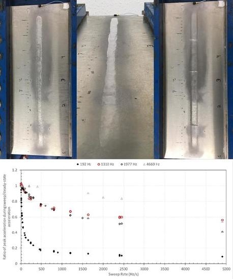
Figure 5 presents the ratio of the maximum acceleration measured during sweep tests compared to the steady-state value in function of sweep rate. As expected, it can be observed that lower sweep rates are required to obtain significant mode deployment at low frequencies. With higher frequencies, faster sweep can be performed to obtain similar maximum acceleration ratio, which means that sweep rate during de-icing tests must take into account the frequency of the targeted modes to ensure sufficient mode deployment and strain generation. At a sweep rate of 4900 Hz/s, the ratio of acceleration compared to steady-state mode is below 0.56 for all the frequencies. At 200 Hz/s the ratio is 0.28 for 192 Hz, 0.84 for 1310 Hz, 0.88 for 1977 Hz and 0.99 for 4669 Hz, while at 20 Hz/s the ratio is above 0.98 for all frequencies except 192 Hz, where it is only 0.62.
Higher frequency equals a shorter time period for vibration cycle, which means that the same number of cycles for a mode occurs in less time than at lower frequency. The time and number of cycles before obtaining 95% of the steady-state acceleration is reached after voltage is applied is compared in Table 1 for the four frequencies investigated. The number of cycles is in the same order of magnitude for all frequencies, ranging from 127 cycles to 297 cycles without a straight relationship to frequency value, while the time greatly diminishes as the frequency increases, from 0.660 s to 0.046 s.
The results of Table 1 show that the transient effects occurring during frequency sweeps do not generate different deployments of the resonant modes and cannot provide increased acceleration values resulting in higher strain and stress generation on the plate. They also demonstrate that resonant modes require a minimum vibration cycle before they reach steady-state regime. During sweeping, if the sweep rate is too high, insufficient vibration cycles are generated, limiting the mode deployment and maximum acceleration amplitude obtained. As expected, as the sweep rate tends towards zero, the acceleration of a resonant mode during the sweep will tend towards its steady-state value. Since a minimum of vibration cycles is required for a complete mode deployment, this implies that at lower frequencies the time required to obtain full acceleration is higher. For this reason, lower sweep rates are required at lower frequencies. The frequency range of the sweep has no impact on the mode deployment and acceleration obtained for a resonant mode, meaning that no effect is transposed from mode to mode during the frequency sweeps performed. These conclusions indicate that frequency sweeps do not increase the amplitude of vibration during the de-icing process by generating higher acceleration or stress/strain on the plate and in an ice layer accumulated on the plate, and steady-state activation of a resonant mode is theoretically the ideal case. However, sweeping can help ensure that a resonant mode is excited by covering a defined frequency range. The exact frequency of a resonant mode will vary in function of the ice accumulation and other ambient condition effect impacting the mass and stiffness of the structure. By performing a frequency sweep, it is not required to target a very precise and specific frequency value that changes as the ice accumulates on the structure, which could be easier and more reliable for a de-icing system. The sweep rate of frequency sweeps, if used, must be studied appropriately to allow for a sufficient mode deployment and strain/stress optimal generation, while still permitting a rapid and efficient de-icing process. The conclusions obtained in this section do not explain the de-icing successes obtained with the frequency sweeps and unsuccessful results with steady-state frequencies in the previous phases of this project.

3. De-Icing Tests with the Experimental Setup

3.1. Materials and Methods

Results and conclusions obtained with the frequency sweep investigation have shown that transient effect during sweeping tests does not provide any benefit in mode deployment and acceleration generation compared to steady-state mode. They demonstrated that acceleration amplitude tends toward steady-state value as the sweeping rate tends towards zero, meaning that steady-state vibration is the ideal case for de-icing tests in term of stress and displacement generation. Since steady-state is the optimal case, this means that in previous works [3,4], where de-icing was unsuccessful in steady-state activation, either the wrong resonant modes were targeted or the frequencies excited did not match the frequencies of the resonant modes targeted due to the impact of the ice layer on structure stiffness and mass. To verify this hypothesis, ice accumulation was performed using the flat plate setup and frequency sweeps were performed to obtain ice layer breaking. A camera was installed above the setup to observe the frequencies and modes at which the breaking occurred. Further tests were conducted in steady-state activation to obtain breaking of the ice layer without frequency sweeps.

3.1.1. Ice Accumulation

The flat plate setup was installed in a cold chamber that can maintain temperatures down to −30 °C. The chamber is equipped with a hydraulic spraying system consisting of a pressurized refrigerator connected to a Spraying systems 650017 nozzle. The water pressure in the system was kept at 80 psi which generated droplets of 115 µm of Median Volumetric Diameter. The nozzle was installed on a translation track over the flat plate setup and was moved along this track at constant speed to evenly distribute water droplets over the length of the plate (Figure 6). Once the nozzle completed a back and forth movement along the track, the spraying was stopped for 10 s before a new spraying run was performed.
The ice layer was accumulated on the plate before each test at a temperature of −8 °C. This temperature allowed for a glaze ice to be generated without liquid water flowing off the ice layer. An aluminum cover with a rectangular slit in the middle was installed on the flat plate setup before each ice accumulation (Figure 7). This allowed the accumulation of a 3 cm wide and 45 cm long ice layer, which was a good representation of ice accumulated on the leading edge portion of a complete profile. The accumulation was done in one hour at a precipitation of 2 mm/h, resulting in a 2 mm thick ice layer. An example of an accumulated ice layer is presented in Figure 8.

3.1.2. Camera

A Blaster ACA1300-200uc camera was installed in the cold room above the flat plate setup (Figure 9). The camera was used to capture multiple pictures during de-icing tests with frequency sweeps to determine the frequencies and resonant modes where cracking and delamination of the ice occurred. The signal generator triggered the camera to synchronise the pictures with the frequency sweep. The camera recorded pictures at a frame rate of 15 pictures/s as well as the time at which the picture was taken. The de-icing test was repeated in steady-state activation at the natural frequencies identified with the camera in the frequency sweep tests to validate the conclusions obtained in Section 2.

3.2. Results

3.2.1. Frequency Sweep De-Icing Tests

Frequency sweep tests were performed with the five piezoelectric actuators activated in phase at 600 Vpp. This activation of all the actuators at a higher voltage favors fracture and delamination of the ice. The first sweep was performed from 160 Hz to 500 Hz. The sweep duration was set to 60 s to obtain a good precision on the frequency values of excitation at which cracking and delamination occurred corresponding to the pictures captured with the camera. It also allowed a sufficient mode deployment with a sweep rate lower than 10 Hz/s. The pictures show that delamination of the ice layer from the flat plate is obtained on one half of the plate after 5.672 s (Figure 10). Delamination can be observed by the emergence of a white layer underneath the clear transparent ice accumulation, due to the presence of air between the substrate and the ice. The corresponding frequency is 194 Hz.
A second test was performed in the frequency range starting at 250 Hz and up to 500 Hz for 60 s, for a sweep rate of 5 Hz/s. This test was performed on a newly accreted ice layer, without delamination or cracking. A single crack was observed during this sweep at the center of the plate after 43.532 s (Figure 11) for a matching frequency of 431 Hz.
The third sweep test ranged from 500 to 1000 Hz. No cracking or delamination of the ice was observed during this test. A fourth sweep was performed from 1000 Hz to 1500 Hz, again in 60 s. A very small incipient delamination on one tip of the ice layer was observed after 13.265 s (Figure 12) with a more significant delamination and cracking in the longitudinal direction after 23.999 and 25.799 s. The ice breaking is observed from 1111 to 1215 Hz. The explanation for this broader frequency range was provided in the third phase of this research project [10].
Similarly to the tests conducted at frequencies of excitation below 500 Hz, an additional sweep test was performed on a newly accreted ice layer in the frequency range from 1250 to 1500 Hz, in 60 s. A single crack was observed after 7.466 s (Figure 13) for a frequency of 1281 Hz.
The use of the camera has allowed to locate two frequencies at which cracking occurs and two frequencies at which delamination occurs. The frequencies and type of ice breaking obtained are presented at Table 2.

3.2.2. Steady-State Mode De-Icing Tests

Using the camera installed in the cold room, it has been possible to determine four natural frequencies at which cracking and delamination of the ice was obtained with frequency sweeps and a summary of those frequencies and the type of ice breaking observed was presented in Table 2. Tests in steady-state excitation were performed at those frequencies to obtain ice breaking and validate conclusions obtained in the first part of this paper. For these tests, ice was accumulated on the flat plate and the accelerometer on the plate was used to determine through the frequency response function the frequency of the resonant modes presented in Table 2. The voltage of excitation during this procedure was kept below 100 Vpp to maintain the integrity of the ice layer on the plate. Once the structural natural frequencies were identified, the voltage of excitation was slowly increased manually until cracking or delamination occurred or up to a maximum voltage of 700 Vpp, to prevent damaging of the actuators. All actuators were activated in phase to replicate the excitation used in the previous section.
The natural frequency of 194 Hz was excited and a delamination of the ice layer was obtained and identified with the camera. Ice was accumulated on the plate and this same resonant frequency was observed at 188 Hz. The voltage was slowly increased manually for this frequency until delamination of the ice was obtained at one extremity of the ice layer at 550 Vpp (Figure 14). The delamination of the ice resulted in a change in the stiffness of the structure which impacted its resonant frequency. After the delamination of the ice, the resonant frequency was observed at 185 Hz. The voltage was increased from 0 Vpp at this new frequency until the delamination zone expended to reach the middle of the plate, at 550 Vpp (Figure 15). This caused a new change in the structural stiffness and the resonant frequency was observed to shift at 183 Hz. The voltage of excitation was slowly increased from 0 up to 575 Vpp, where the delamination zone exanded to the other end of the ice layer (Figure 16).
Let us consider the case of steady-state excitation at the natural frequency of 431 Hz at which cracking of the ice layer was obtained resulting in one crack in the center of the plate. After ice accumulation, the resonant frequency was observed to shift at 438 Hz. Sinusoidal amplitude (voltage) of excitation was increased until a single crack was obtained at 12 cm from the edge of the plate at 300 Vpp (Figure 17). The cracking of the ice layer results in a change of the stiffness of the ice covered plate which change the frequency of the resonant mode. The new frequency of the mode was determined with the same method and was observed at 426 Hz. Tests at different voltage were performed with the same procedure and a new crack was obtained close to the center of the plate at 336 Vpp. This new crack once again resulted in a change of the stiffness with a shift of the resonant frequency at 418 Hz. A last crack was obtained on the other half of the plate for a sinusoidal excitation of 380 Vpp.
Delamination and longitudinal cracking was observed between 1111 Hz and 1215 Hz. A resonant mode was identified at 1138 Hz at a low amplitudes of excitation. In a similar way as described previously, the voltage of excitation was increased and delamination on both edges of the ice layer was obtained at 340 Vpp (Figure 18).
The second mode identified using the high-speed camera where a cracking occurred was at 1281 Hz. After the ice accumulation, the resonant frequency of the structure was observed at 1338 Hz. The sinusoidal amplitude of excitation (voltage) was gradually increased to 320 Vpp, where a crack appeared at 11 mm from the edge (Figure 19).

3.3. Discussion

In the first section of this paper, vibration response of the plate to frequency sweep excitations has been studied. The results have shown that a minimum number of excitation cycles is required for the plate to reach maximum magnitude of vibration during a frequency sweep. If the frequency sweep rate is too high, the resonant modes excited will not reach maximum vibration amplitudes. As the sweep duration is increased (lower sweep rate), the vibration of the plate will tend to reach the value of the steady-state excitation, where maximum mode deployment is obtained. No other effects are observed during frequency sweep tests, meaning that steady-state is the optimal activation for de-icing. Frequency sweeps, if done at a proper sweeping rate, can achieve the same results as steady-state activation and at lower frequencies, lower sweep rates are required to reach the same percentage of the steady-state value.
To validate those conclusions, a camera was installed in the cold room and resonant frequencies of the structure at which breaking of the ice layer occurred during frequency sweeps were determined. The use of the camera has allowed to identify two frequencies at which cracking occurred and two frequencies at which delamination occurred. The delamination obtained in those tests was due to an adhesive break. In a previous study [3], it was shown that two different delamination scenarios can be obtained during de-icing tests, an adhesive break and a cohesive break at the interface. The type of interface break is mainly defined by the atmospheric condition of accumulation of the ice as well as the surface parameters like roughness and thermal conductivity. Studies have been done on the subject where the impact of surface roughness structure was investigated on ice adhesion, from standard surface finish to specially engineered surface topography like hydrophobic and icephobic surfaces [11,12,13]. For an unpolished metal plate of standard mill finish similar to the one used in this study and at the selected accumulation conditions for the testing, Guerin has demonstrated that ice shows adhesive delamination [14], which is in consensus with the obtained results. Adhesion stresses involved in the ice delamination is investigated in another paper on the subject [10]. In the third frequency sweep performed, from 500 to 1000 Hz, no cracking or delamination was obtained.
Testing was subsequently performed at fixed frequency in steady-state activation at the four frequencies obtained. The tests have proven that it is possible to obtain cracking and delamination of the ice layer on the flat plate in steady-state activation, without sweeping, which confirms the conclusions that maximum acceleration and mode deployment is obtained in steady-state mode and that adjacent modes excited during sweeping are not required to help cracking and delamination. It also points out the importance of correctly determining which mode can lead to de-icing and the exact frequency of the resonant mode to achieve de-icing. De-icing was obtained in steady-state activation, which was not successful in the previous works done on the subject in the laboratory [3,4]. During those studies, de-icing in steady-state mode was tried by using frequencies selected arbitrarily from their mode shapes and accelerometers were not used to their full potential to identify the actual frequency of the mode once ice was accumulated. The ice layer accumulations on the plate modify the stiffness of the structure and the frequencies of the resonant modes. Repeatability of the ice layer accumulation creates variation in the resulting resonant frequency for each mode between each ice accumulation, making it impossible to determine the exact frequency without measuring it. If the excitation is not done at the exact frequency, acceleration and stress generation will be sub-optimal, only a small fraction of those obtained at the exact frequency and de-icing will not occur. This explains the lack of success from previous studies: even if steady-state mode is the optimal activation, it is less practical and harder to achieve without the use of the right tools. Frequency sweeps were used to find frequencies where ice breaking occurred, showing the necessity of developing a numerical model and limit criteria to determine the resonant modes susceptible of generating de-icing in order to use steady-state activation without frequency sweeps.
Results have also showed that breaking of the ice layer affects the bending stiffness of the ice/plate structure. This change in stiffness lowers the frequency of the resonant modes. Performing frequency sweep backwards, from the highest frequency to the lowest, should be more effective for de-icing by activating multiple time the same resonant mode. For example, the delamination obtained during the sweep performed from 160 to 500 Hz (Figure 10) is similar to the first delamination obtained in steady-state mode at the corresponding frequency (Figure 14). If the frequency sweep had been performed backwards, the delamination obtained would have correspond to the delamination obtained after the third steady-state activation by activating the mode at 188 Hz, 185 Hz and 183 Hz (Figure 16). Sweeping at proper sweep rate could be performed from highest to lowest frequency for more efficiency by re-exciting the same mode multiple time in a single sweep. The results and conclusions obtained on piezoelectric actuator excitation based system will be applicable for blade structures, even if the difference in geometry will impact the mode shapes and the natural frequencies as well as the stress generated. Moreover, such a system needs to take into account aerodynamic forces as well as centrifugal forces occurring during blade rotation. Investigation of stress generation and system’s ability to create de-icing was pursued in the third part of this project [10].

Author Contributions

Conceptualization and methodology, E.V., C.V. and S.G.; validation, E.V.; formal analysis, E.V.; investigation, E.V.; data curation, E.V.; writing—original draft preparation, E.V.; writing—review and editing, C.V. and S.G.; supervision, C.V. and S.G. All authors have read and agreed to the published version of the manuscript.

Funding

This research was funded jointly by the CRIAQ/CARIC (Grant Number ENV-702), CRSNG (Grant Number CRD 478088-14), Bell Textron and Socomore.

Conflicts of Interest

The authors declare no conflict of interest.

References

  1. Coffman, H.J., Jr. Helicopter Rotor Icing Protection Methods. J. Am. Helicopter Soc. 1987, 32, 34–39. [Google Scholar] [CrossRef]
  2. Villeneuve, E.; Volat, C.; Ghinet, S. Numerical and experimental investigation of the design of a piezoelectric de-icing system for small rotorcraft part 1/3: Development of a flat plate numerical model with experimental validation. Aerospace 2020. submitted. [Google Scholar]
  3. Harvey, D. Modélisation Numérique d’un Système de Protection Contre le Givre par Éléments Piézoélectriques Avec Validation Expérimentale; Département des Sciences Appliquées, Université du Québec à Chicoutimi: Saguenay, QC, Canada, 2012; p. 297. [Google Scholar]
  4. Villeneuve, E.; Harvey, D.; Zimcik, D.; Perron, J.; Aubert, R. Piezoelectric De-Icing System for Rotorcraft. J. Am. Helicopter Soc. 2015, 60, 12. [Google Scholar] [CrossRef]
  5. Forsyth, E.M.; Warburton, G.B. Transient vibration of rectangular plates. J. Mech. Eng. Sci. 1960, 2, 325–330. [Google Scholar] [CrossRef]
  6. Mochida, Y.; Ilanko, S. Transient vibration analysis of a completely free plate using modes obtained by Gorman’s Superposition Method. J. Sound Vib. 2010, 329, 1890–1900. [Google Scholar] [CrossRef] [Green Version]
  7. Rock, T.; Hinton, E. Free vibration and transient response of thick and thin plates using the finite element method. Earthq. Eng. Struct. Dyn. 1974, 3, 51–63. [Google Scholar] [CrossRef]
  8. Wu, J.-S.; Lee, M.L.; Lai, T.S. The dynamic analysis of a flat plate under a moving load by the finite element method. Int. J. Numer. Methods Eng. 1995, 193, 307–314. [Google Scholar] [CrossRef]
  9. Kim, T.; Lee, U. Vibration Analysis of Thin Plate Structures Subjected to a Moving Force Using Frequency-Domain Spectral Element Method. Shock Vib. 2018, 2018, 27. [Google Scholar] [CrossRef]
  10. Villeneuve, E.; Volat, C.; Ghinet, S. Numerical and Experimental investigation of the design of a piezoelectric de-icing system for small rotorcraft part 3/3: Numerical model and experimental validation of vibration based de-icing of a flat plate structure. Aerospace 2020. submitted. [Google Scholar]
  11. Hejazi, V.; Sobolev, K.; Nosonovsky, M. From superhydrophobicity to icephobicity: Forces and interaction analysis. Sci. Rep. 2013, 3, 2194. [Google Scholar] [CrossRef] [PubMed] [Green Version]
  12. Ling, E.J.Y.; Uong, V.; Renault-Crispo, J.; Kietzig, A.; Servio, P. Reducing Ice Adhesion on Nonsmooth Metallic Surfaces: Wettability and Topography Effects. ACS Appl. Mater. Interfaces 2016, 8, 8789–8800. [Google Scholar] [CrossRef] [PubMed]
  13. Starostin, A.V.V.; Barkay, Z.; Legchenkova, I.; Danchuk, V.; Bormashenko, E. Drop-wise and film-wise water condensation processes occurring on metallic micro-scaled surfaces. Appl. Surf. Sci. 2018, 444, 604–609. [Google Scholar] [CrossRef] [Green Version]
  14. Guerin, F.; Laforte, C.; Farinas, M.; Perron, J. Analytical Model Based on Experimental Data of Centrifuge Ice Adhesion Tests with Different Substrates. Cold Reg. Sci. Technol. 2016, 121, 93–99. [Google Scholar] [CrossRef]
Figure 1. Flat plate experimental setup.
Aerospace 07 00049 g001
Figure 2. Piezoelectric actuator patches bonded to flat plate.
Aerospace 07 00049 g002
Figure 3. Acceleration at the plate’s end for a frequency sweep of 100 Hz to 2500 Hz at 200 Vpp for piezoelectric actuator 4 (a) and actuator 5 (b).
Aerospace 07 00049 g003aAerospace 07 00049 g003b
Figure 4. Maximum acceleration on plate edge for frequency sweeps at different frequency ranges in function of the sweep rate at 200 Vpp with the piezoelectric actuator 5 at 192 Hz (a), 1310 Hz (b), 1977 Hz (c) and 4669 Hz (d).
Aerospace 07 00049 g004aAerospace 07 00049 g004b
Figure 5. Ratio of the peak acceleration during sweep tests on the acceleration in steady-state activation.
Aerospace 07 00049 g005
Figure 6. Spray nozzle installed on translation track.
Aerospace 07 00049 g006
Figure 7. Aluminum cover for ice accumulation.
Aerospace 07 00049 g007
Figure 8. Ice layer accumulated on the flat plate setup.
Aerospace 07 00049 g008
Figure 9. Camera installed over flat plate setup.
Aerospace 07 00049 g009
Figure 10. Pictures captured after 5.568 (a) and 5.672 s (b) with the camera during a frequency sweep from 160 to 500 Hz in 60 s with the five actuators activated in phase at 600 Vpp.
Aerospace 07 00049 g010
Figure 11. Pictures captured after 43.465 (a) and 43.532 s (b) with the camera during a frequency sweep from 250 to 500 Hz in 60 s with the five actuators activated in phase at 600 Vpp.
Aerospace 07 00049 g011
Figure 12. Pictures captured after 13.265 (a), 13.333 (b), 23.999 (c) and 25.799 s (d) with the camera during a frequency sweep from 1000 to 1500 Hz in 60 s with the five actuators activated in phase at 600 Vpp.
Aerospace 07 00049 g012
Figure 13. Pictures captured after 7.399 (a) and 7.466 s (b) with the camera during a frequency sweep from 1250 to 1500 Hz in 60 s with the five actuators activated in phase at 600 Vpp.
Aerospace 07 00049 g013
Figure 14. Delamination of the ice at 550 Vpp in steady-state activation with all piezoelectric actuators activated in phase at 188 Hz.
Aerospace 07 00049 g014
Figure 15. Delamination of the ice at 550 Vpp in steady-state activation with all piezoelectric actuators activated in phase at 185 Hz.
Aerospace 07 00049 g015
Figure 16. Delamination of the ice at 575 Vpp in steady-state activation with all piezoelectric actuators activated in phase at 183 Hz.
Aerospace 07 00049 g016
Figure 17. Cracking of the ice layer in steady-state mode at 438 Hz and 300 Vpp (left), 426 Hz and 336 Vpp (middle) and 418 Hz and 380 Vpp (right).
Aerospace 07 00049 g017
Figure 18. Delamination of the ice layer in steady-state mode activation at 1138 Hz and 340 Vpp.
Aerospace 07 00049 g018
Figure 19. Cracking of the ice layer in steady-state mode at 1338 Hz and 320 Vpp.
Aerospace 07 00049 g019
Table 1. Number of cycles and time to reach steady-state regime.
Frequency (Hz)Nb of CyclesTime
(s)
1921270.660
13102970.227
19772300.116
46692150.046
Table 2. Frequencies and type of ice breaking obtained with camera tests.
Frequency (Hz)Type of Ice Breaking
194Delamination
431Crack
1111 to 1215Delamination
1281Crack

