1. Introduction
As part of the Collaborative Research Center 880 “Fundamentals of High Lift for Future Commercial Aircraft”, the Technical University of Braunschweig and the German Aerospace Center (DLR) developed an adaptive wing profile for novel high-lift devices. The increase in future air traffic will lead to additional flights from smaller airports near urban areas. Therefore, measures must be taken to re-duce the noise level during take-off and landing phases. The efficiency of short take-off and landing (STOL) aircraft depends particularly on the achievable lift co-efficient, induced by supplementary high-lift devices. A first step to optimize the performance of commercial aircraft could be the structurally compliant integration of sensors and actuators for active flow control into the wing profile, to save weight and to reduce drag. The objective is the development of an adaptive wing, which includes all relevant systems for active flow control to allow the implementation of novel high-lift devices, which adapt to each flight phase. This work employs the internal blowing over carefully designed flap surfaces to achieve control authority for flow turning, hence making use of the Coanda effect [
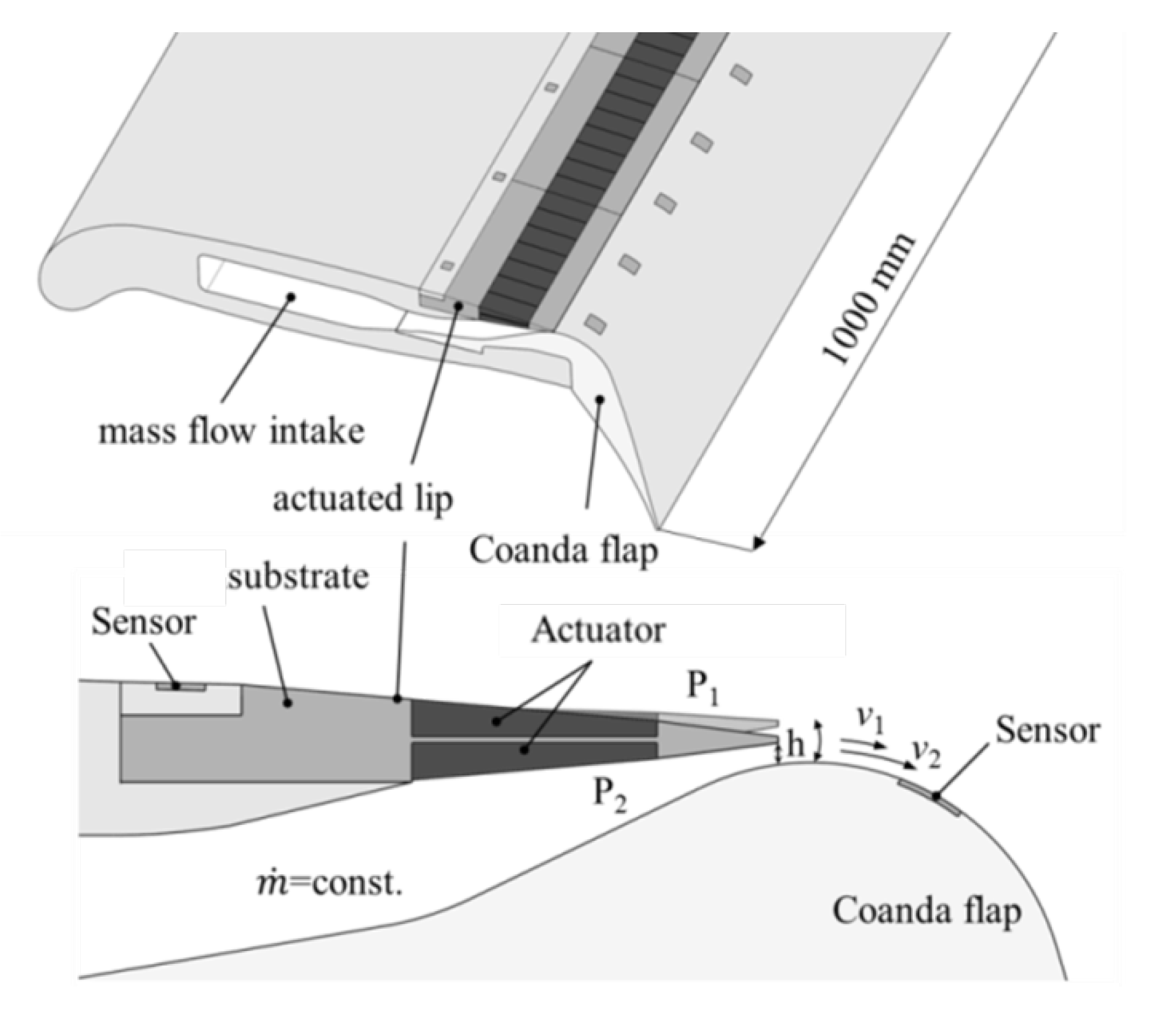
1]. One part of this system is a very compact actuated lip of a blowing slot ahead of a Coanda flap. To avoid flow separation on the Coanda flap, a closed loop-controlled system is developed in order to dynamically adjust the Coanda jet to the current state of flight. The flow condition is measured using micro engineered pressure and hot film sensors, which are integrated into the wing profile. Using an additional pressurized mass flow ṁ, the velocity of the Coanda jet is controlled by an adaptive lip that varies the height h of the blowing slot (
Figure 1).
It has been proven that active flow control (AFC) with periodic actuation provides aerodynamic advantages (e.g., [
2,
3,
4]). These advantages result from the power reduction compared to continuous operation of the flow control system. The effectiveness of periodic actuation is based on the exploitation of flow instabilities in contrast to a steady actuation that tries to change the flow topology by momentum injection. Circulation control in combination with high lift devices offers several advantages compared with conventional high lift configuration. The basic concept of circulation control includes the Coanda principle, in which energy is introduced into the flow by means of a thin jet that is ejected tangentially from a slot near the trailing edge. The main advantage of circulation control is increased lifting capacity, which enables shorter take-offs and landings. This technology was patented in 1960 by Davidson [
5] and has been studied in various publications since then [
6,
7,
8]. A circulation control wing (CCW) with steady jets has been shown to provide lift coefficients that are comparable or superior to conventional high lift systems, even with very small mass flows [
9,
10]. A special variant of the circulation control is the Coanda flap, with the objective to keep the flow attached over a highly deflected flap, by blowing a jet tangentially over the specially designed surface contour. This concept has already been examined and geometrically optimized in several previous studies [
11,
12,
13]. To the best of the authors’ knowledge, an actuator concept with the complexity presented in this study has not yet been investigated.
2. Requirements and Actuation Principle
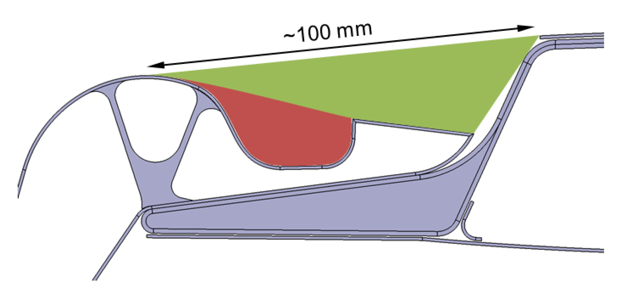
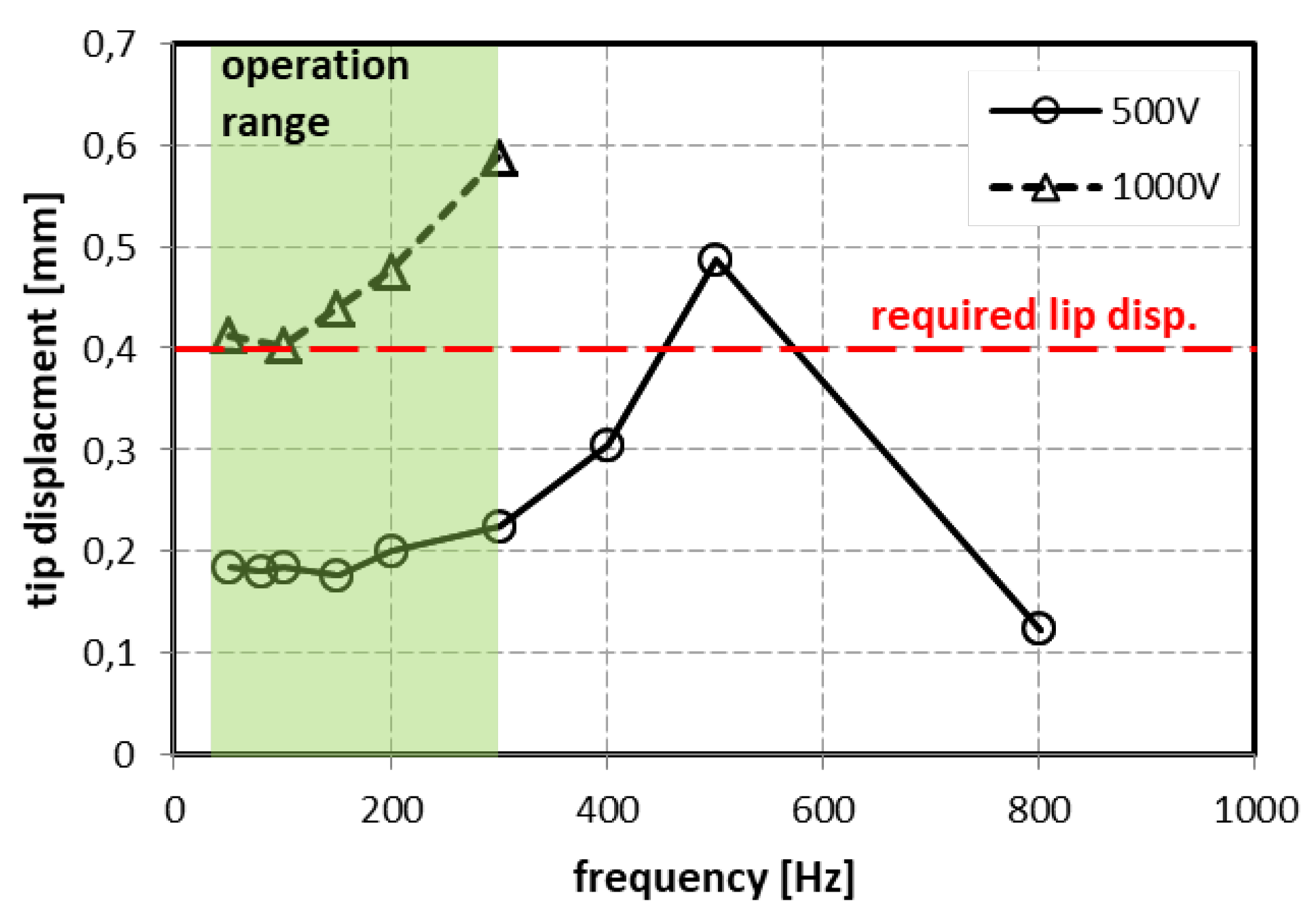
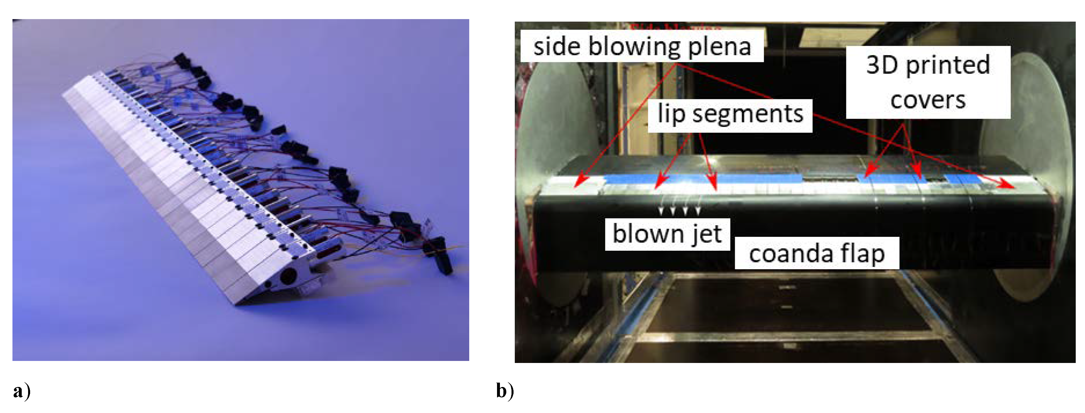
As part of this work, a scaled wind tunnel model with a span of 1 m and a chord of 600 mm has to be equipped with the active lip. The very limited dimensions of the scaled wind tunnel model represent an enormous challenge for the development of the active system (
Figure 2). Additionally, there are requirements that result from the aerodynamic function of the lip. The main requirements are an operating frequency of up to f = 300 Hz, an active displacement of h = 0.4 mm at the tip of the lip, and the operability at a plenum pressure of 1 bar. Besides this, there is the necessity for a lightweight design to keep the resonance frequency of the system above 300 Hz. To allow a span wise variable actuation (3D-actuation), the lip is subdivided into 33 individually controllable segments with a width of 29 mm each. This segmentation is a compromise between aerodynamic resolution and complexity of the mechanical system.
Another requirement arises from the practical operation of the system. Differences in the rigidity of the lip segments and assembly tolerances must be compensated by an adjustment mechanism of the lip segments so that the gap height can be set precisely to calibrate each lip segment.
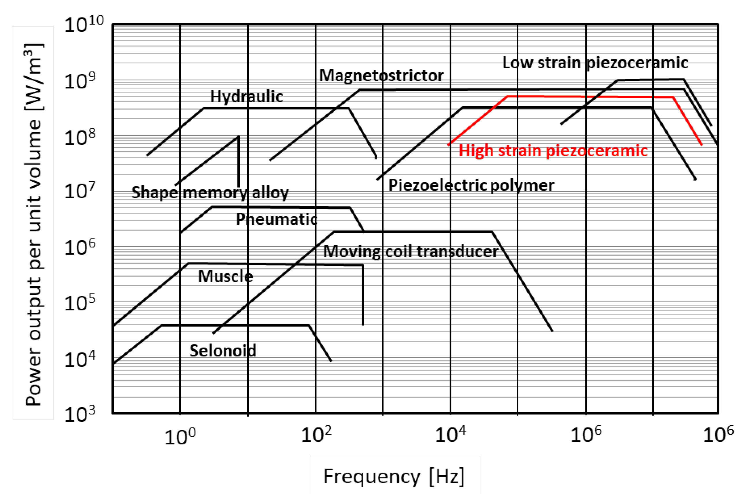
Based on these requirements, it became clear that the task can only be solved with a solid-state actuator. Mechanical systems based on electromagnetic, pneumatic or hydraulic concepts are either too bulky, or their dynamics are too limited. The diagram in
Figure 3 shows a comparison of different actuators by means of power output per unit volume and operation frequency [
14]. Compared to other actuation concepts, piezoceramics in particular have very good properties in this regard. Taking these considerations into account, a concept based on piezoceramic actuators was selected. The major disadvantage of piezoceramic actuators is their low stroke. For piezo actuators using the larger longitudinal effect (or d
33-effect), the free active strain is approx. 1000 µm/m. In order to achieve the required deflection of 0.4 mm, an amplification of the actuator stroke is therefore necessary. For this purpose, two different amplification concepts were examined for their principal applicability to this problem.
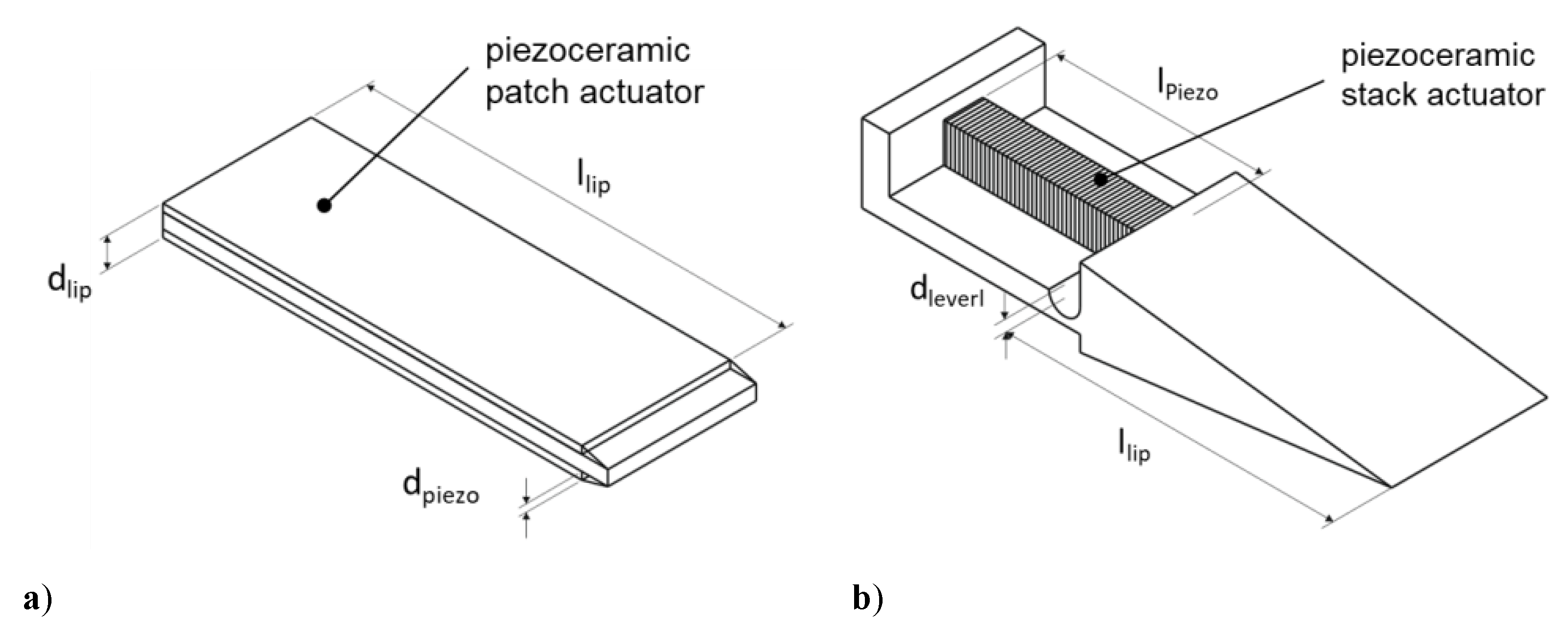
The first concept is based on a piezoceramic bender configuration, as depicted in
Figure 4a. The principle is based on thin piezoceramic patch actuators that are bonded to a structural substrate. A contraction or expansion of the piezoceramic patch leads to a bending deformation of the assembly. A basic distinction is made between a monomorph-, bimorph- or trimorph configuration. In a monomorph configuration, a single piezoceramic layer is applied to the substrate. In the bimorph configuration, two piezoceramic layers, without a structural substrate, are arranged one above the other. In the trimorph configuration, there are two piezoceramic layers, which are usually arranged symmetrically with a substrate material. Each of these configurations has advantages and disadvantages in terms of maximum deflection and achievable forces and rigidity. In particular, rigidity plays a major role, since the deformations due to the aerodynamic loads should be as small as possible, in order to enable a precise adjustment of the blowing slot. With this in mind, trimorph configurations are most suitable for this task, because they achieve the best ratio of stiffness to active deflection. In order to increase the rigidity and blocking force, it is possible to arrange several layers of piezoceramic patch actuators on top of each other. However, this leads to a reduction in free deflection. To ease this problem, the number of piezoceramic layers can be successively reduced, starting from the clamping of the bending transducer. However, the manufacturing of such configurations is complex, costly and error-prone.
For piezoceramic patch actuators, only the longitudinal (d
33-effect) and the transversal (d
31-effect) effect are used for technically relevant applications [
15]. The arrangement of the electrodes determines which effect will be used. The simplest configuration can be realized by using the d
31 effect. In this case, the in-plane contraction of the piezoceramic material (i.e., Poisson’s ratio effect) is used when a positive electrical field is applied in a direction normal to the thickness of the piezoceramic material (usually a thin piezoceramic plate). Thus, the piezoceramic plate is provided with very thin layers of conductive material (a few µm), to build uniform surface electrodes. The electrical field is generated homogenously between these electrodes. The thickness of the piezoceramic plate defines the distance between the upper and lower electrode, and therefore the voltage that is needed to generate a certain electrical field. With a usual plate thickness of 0.2 mm, a voltage of 200 V is necessary to generate an electrical field of 1 kV/mm.
Up to three times higher deformations can be achieved with the d
33-effect. In this case, the electrical field and the effective deformation are in the same direction. Applying a positive field will result in an expansion of the piezoceramic device in the direction of the field and a contraction perpendicular to this direction. The challenge is the generation of an in-plane electrical field. A feasible technical solution is the use of interdigitated electrodes [
16,
17]. Usually, the electrodes are made of two comb-like electrodes with opposite polarity, which are applied on the surface of the piezoceramic material. The electrical field is generated between the fingers of the electrode and penetrates the piezoceramic material. Due to this design, the electrical fields are not very homogenous. This has a direct impact on the minimum electrode distance and hence on the operating voltage. If the distance between the electrode fingers is too small in comparison to the thickness of the piezoceramic material, the electrical field cannot sufficiently penetrate the piezoceramic material and the efficiency of the actuator is reduced. Additionally, the areas directly below the electrode fingers do not contribute to the actuation strain. If the electrode distance is reduced, the number of electrode fingers increases, as does the “dead” area below the electrodes. This can only partly be compensated by using very thin electrode fingers. Besides technical limitations in producing very thin electrode fingers, such a configuration will also cause very high electrical field gradients in the vicinity of the electrodes. These high gradients lead to high mechanical loads in the piezoceramic material, resulting in an impact on lifetime and durability. A suitable electrode distance for a piezoceramic device with a thickness of 0.2 mm is between 0.5 and 1 mm. In this case, without considering the field inhomogeneity, a voltage of 500–1000 V is necessary to generate an electrical field of 1 kV/mm. Despite the higher electrical voltage and the more complex structure, it is crucial for this task to select an actuation principle that generates maximum deflection, and it is therefore necessary to only consider d
33 patch actuators.
The second concept is based on a compliant leverage mechanism with a piezoceramic stack actuator, as depicted in
Figure 4b. A piezoceramic stack actuator consists of a large number of piezoceramic plates, that are stacked on top of each other and generally glued together. The plates are provided with surface electrodes and expand in the thickness direction when an electric field is applied, in accordance with the d
33-effect. The maximum stroke of the actuator is defined by the number of plates, while the operating voltage is determined by the thickness of the individual plates. A distinction is typically made between high- and low voltage stack actuators. Low-voltage actuators are typically built up from plates with a thickness of 0.2 mm and require an electrical voltage of up to 400 V. The plates of high-voltage actuators are usually 0.5 mm thick and are operated with a voltage of 1000 V. High-voltage actuators have the advantage over low-voltage actuators that they have a higher rigidity, since fewer adhesive layers are required to produce a stack of the same length, and therefore active deflection. In addition to glued stack actuators, so-called multilayer stack actuators are also available. Here, the electrodes are sintered directly into the ceramic body as thin layers and therefore have little effect on the stiffness of the actuator. This design allows very small electrode spacings, which enables operating voltages of less than 100 V. Due to their special design, the maximum dimensions of such a multilayer stack are limited, as large parts cannot be sintered in one piece. However, it must be noted that the electrical power required for the operation of the actuators is approximately the same for all variants, since a smaller electrode distance is always accompanied by an increase in the capacity of the actuator.
The various actuator concepts were qualitatively assessed based on the requirements described above. The analysis showed that it is only possible with extremely complex piezoceramic bender configurations to meet the requirements regarding rigidity. The result of this assessment is summarized in
Table 1. The evaluation shows that the variant with a compliant leverage mechanism is most advantageous and that the advantages outweigh the disadvantages.
3. Detailed Design of the Actuation Mechanism
For the detailed design of the active lip, it was first investigated which piezoceramic stack actuators are best suited for this application. Depending on the length of the lip (l
lip) and the leverage (d
lever), Equation (1) describes, which actuator stroke (s
act) is required to achieve a deflection of s
tip at the tip of the lip. Assuming a deflection of s
tip = 0.5 mm (0.4 mm is required) the result of this equation is depicted in
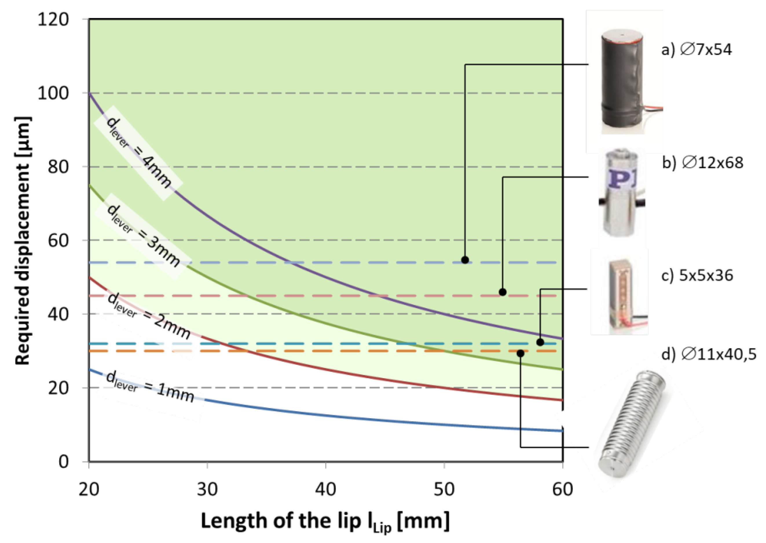
Figure 5 for different leverages.
The green area in
Figure 5 indicates leverages above 2 mm. The smaller the leverage, the greater the gear ratio, but the greater the mechanical load on the mechanism. Furthermore, the lever length cannot be chosen too short from a design point of view. Based on these considerations, the minimum lever length was set to 2 mm. In addition, the stroke of various commercial piezo stack actuators is plotted in the diagram. The best performance is shown by a high-voltage actuator that generates a stroke of 60 µm, with a length of 54 mm (type P-010.40 [
18]). With a lip length of less than 30 mm, this actuator already achieves the required deflection at the tip of the lip.
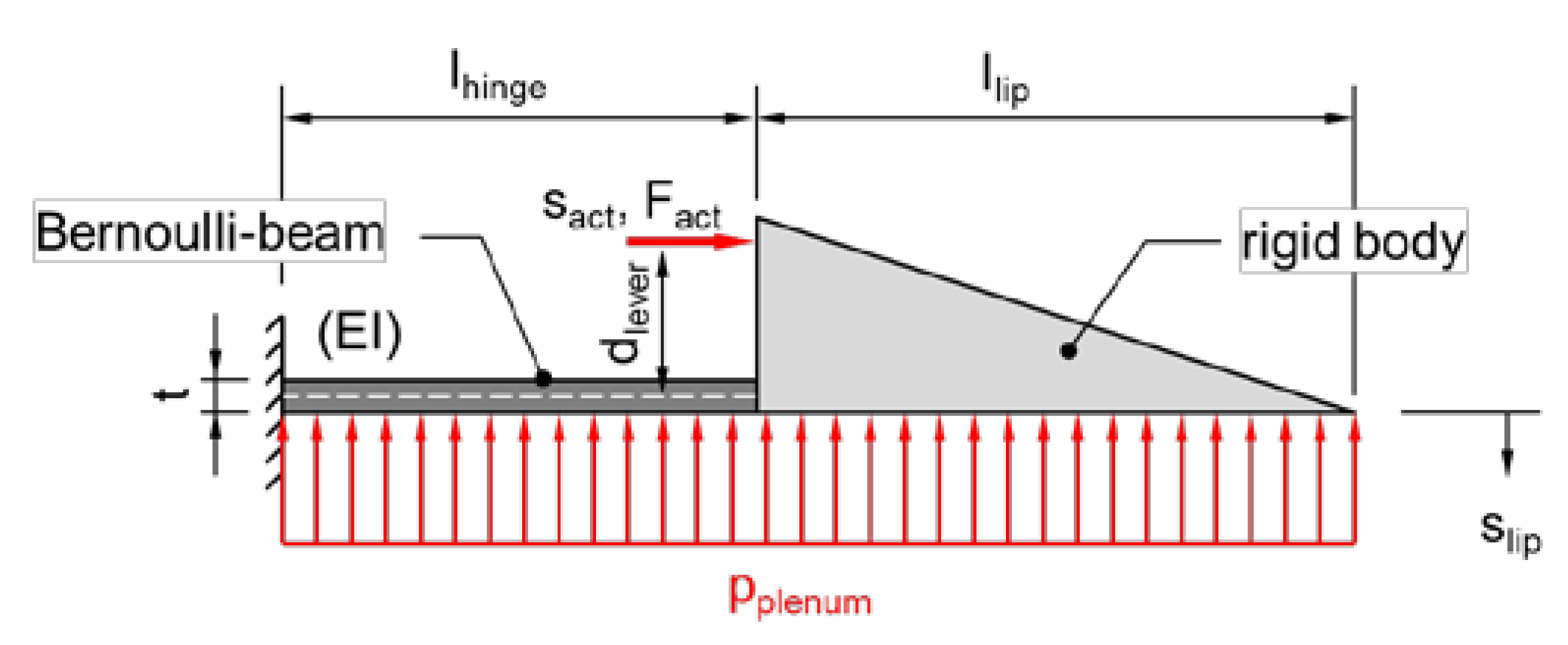
Based on these considerations, a more detailed analytical model based on a Bernoulli beam to describe the compliant hinge was created as shown in
Figure 6. Neglecting the plenum pressure, the free deflection at the lip tip can be calculated using Equation (2), where E denotes the modulus of elasticity and I
y the area moment of inertia of the hinge.
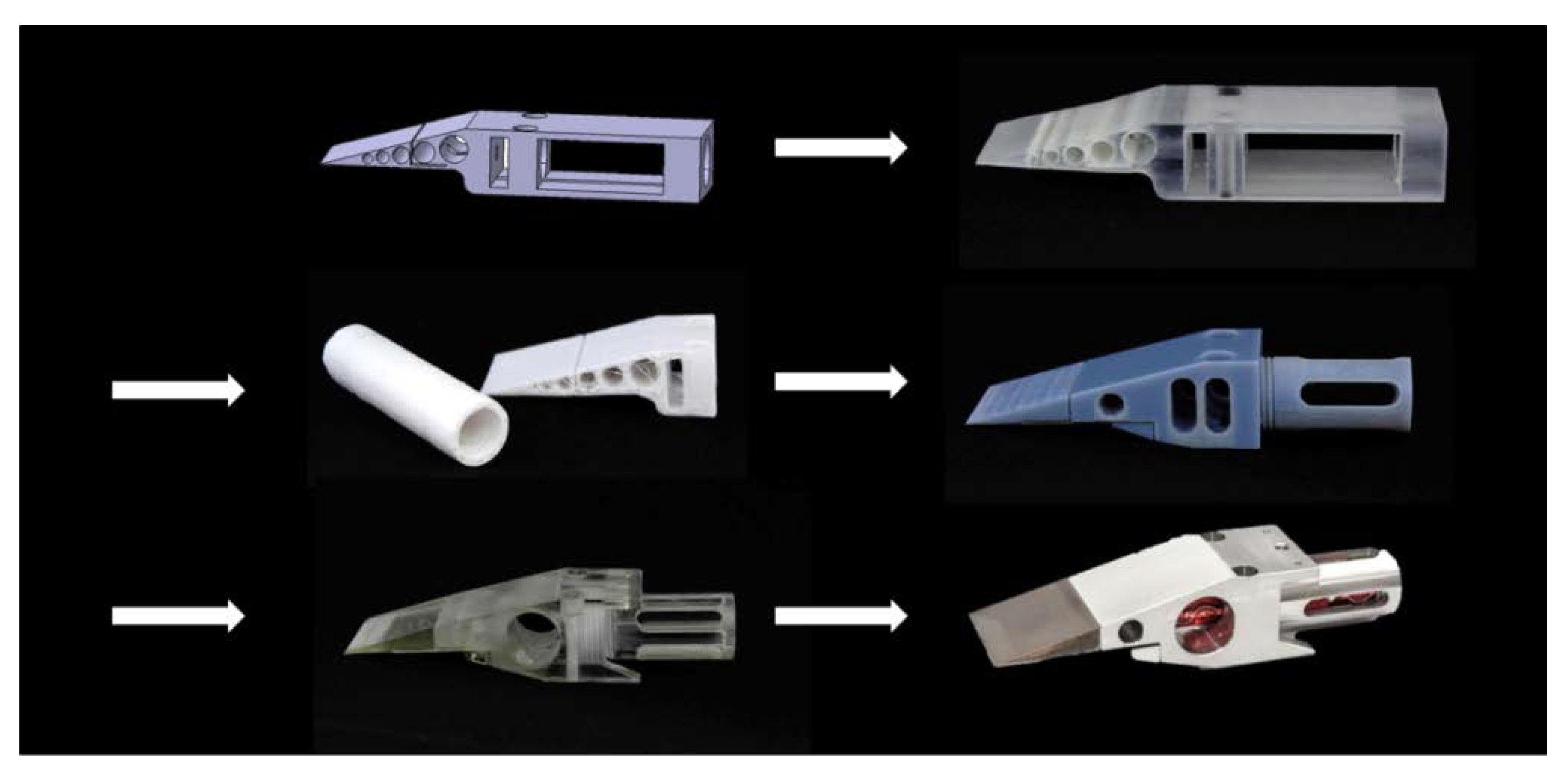
A parameter study was carried out to investigate the influence of different configurations. As mentioned before, the deflection of the lip strongly depends on the distance between the neutral fiber of the solid-state hinge and the axis of force application point (dlever). The detailed design of the actuated lip was then developed in an iterative process. Finite element models were used for stress analysis and to determine the deformation behavior of the lip under aerodynamic loads. During this phase, several prototypes were built and tested with 3D printing technologies, to allow an evaluation of the concept at an early stage.
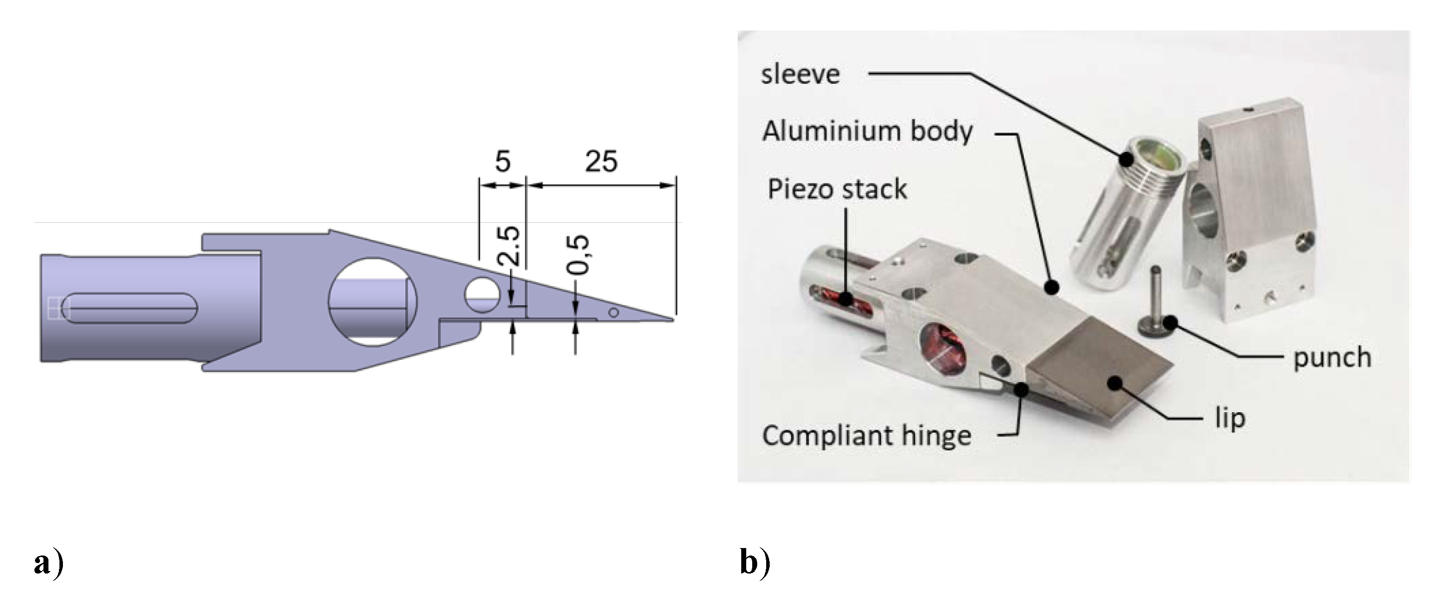
The final design of the lip segment is equipped with the high voltage piezoelectric stack actuator mentioned before, having a length of 56 mm and a diameter of 10 mm (type P-010.40 Physik Instrumente (PI) Ceramic). This actuator generates a free displacement of 60 µm and has a blocking force of 2.2 kN. The lever mechanisms translate this stroke into a 0.6 mm movement of the lip tip in the unloaded case and 0.4 mm in the loaded case (1 bar plenum pressure). The flexure hinge is composed of a carbon fiber laminate with a thickness of 0.5 mm. To reduce the weight of the lip, the main body is made of aluminum, whereas the lip tip is made of hardened steel to provide sufficient wear resistance and stiffness against aerodynamic loads. Because of the limited available space, and due to the requirement that no components should protrude from the aerodynamic contour, a punch is used to transfer the deflection of the actuator to the tip of the lip. This punch is guided into a Teflon sleeve in the aluminum body in order to minimize friction losses. The stack actuator itself is inserted in an aluminum sleeve, which is screwed into the aluminum body with a thread. The position of the lip tip can be adjusted by screwing the aluminum sleeve in and out. Once the correct position has been found, the sleeve can be fixed with a clamping screw. The final dimensions and design of the different components of the lip are shown in
Figure 7.
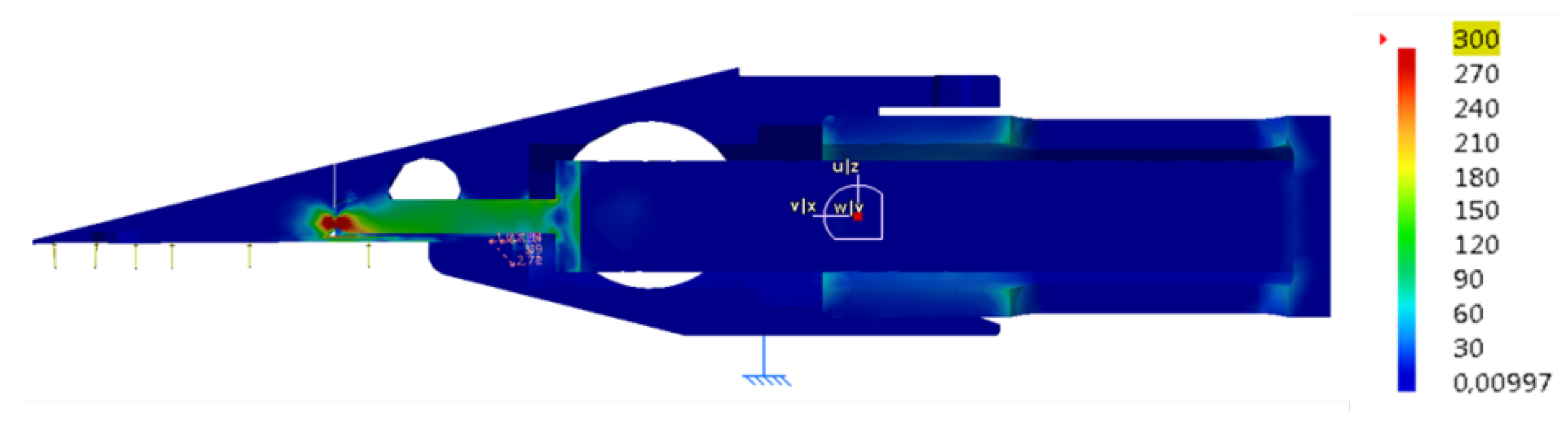
The design process of the lip segment was accompanied by various finite element simulations, in order to examine critical components in more detail. Since the entire mechanical design of the lip was carried out in CATIA V5 (Dassault Systèmes, Vélizy-Villacoublay, France), the finite element program integrated in CATI V5 was used for this purpose. The actuation of the piezo stack is modelled using the thermomechanical analogon (the piezoelectric coefficient is represented by a matched coefficient of thermal expansion).
Figure 8 illustrates an exemplary result of such a simulation. With the finite element model, it can be shown that the influence of the Teflon sleeve, in view of actuation losses, is sufficiently low. Later, lab experiments prove those results. To get an assessment of the von Mises stress, the pressure was increased up to one bar. The largest stress is expected at the contact point between the punch and the metal lip. Therefore, those two parts are made of hardened steel.
Rapid prototyping was used at an early stage of the design process, to support the development process. With the help of 3D printing, it was possible to verify the kinematics, as well as the geometric properties. The design at the starting point was a single-piece box-shaped actuator, shown in
Figure 9 on the top left.
5. Conclusions
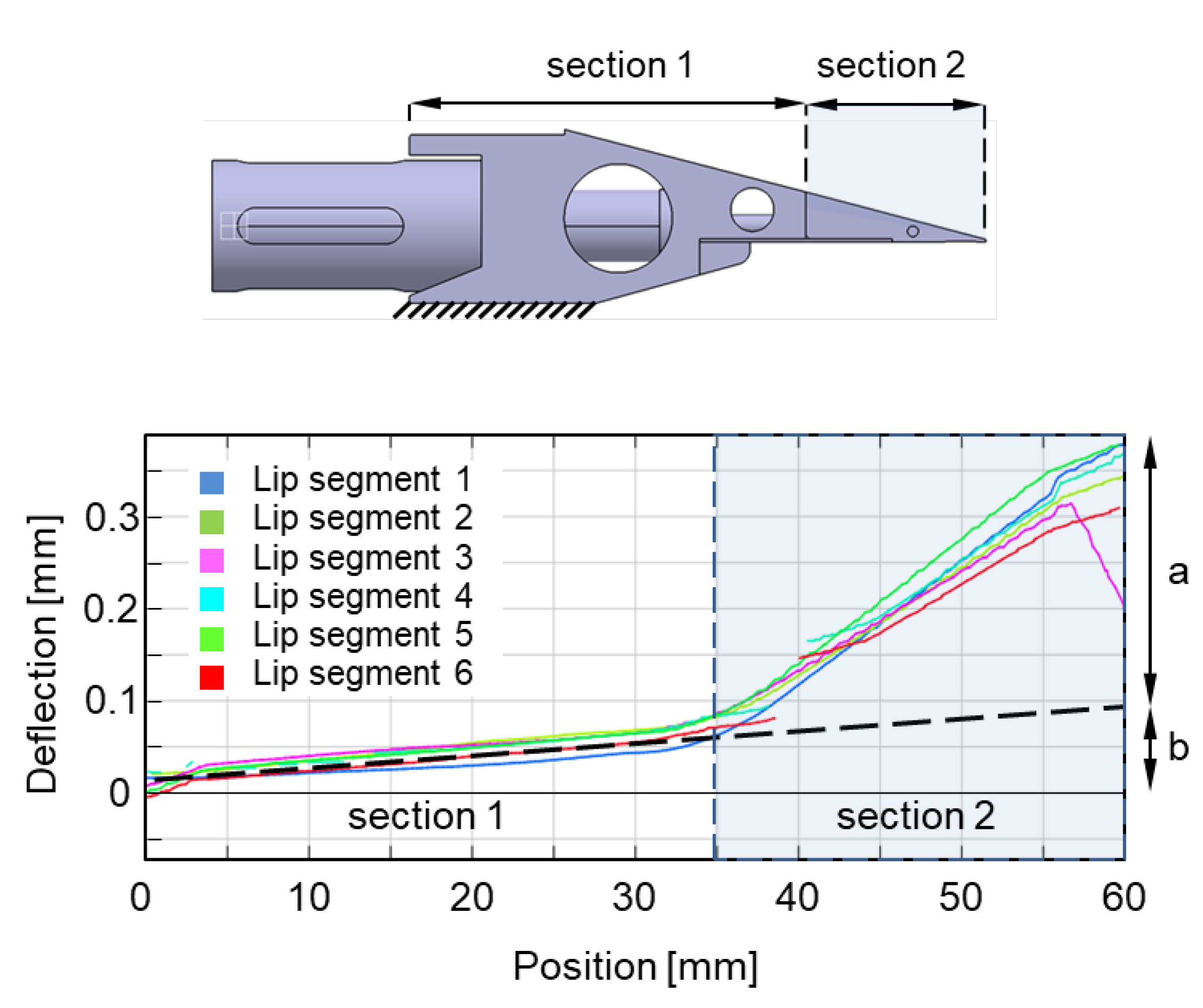
As part of this work, an actuator concept for active flow control of a blown Coanda flap was developed. To meet the challenging requirements with regard to installation space, dynamics and rigidity, the concept is based on a piezoceramic stack actuator in combination with a compliant lever mechanism. Prototypes were developed and tested in an iterative design process. It was shown that the actuator can adjust the height of the blowing slot under pressure over the entire frequency range. Long-term tests demonstrated that the system shows no signs of wear or performance loss, even after 5 × 10⁸ load cycles. A wind tunnel model with a span of 1 m and a chord of 0.6 m was equipped with 33 individual actuators, to allow 3D-actuation of the blowing slot. The deformation behavior of the active lip was extensively investigated with high resolution using the Digital Image Correlation technique (DIC). The flexibility of the entire mechanical system plays a major role in setting the slot to the required tolerances and must be taken into account when installing the system. It is therefore necessary to adjust the system with a pressurized plenum, since the deformations that occur under pressure are in the order of magnitude of the active deflection of the lip. This process is very complex and must be carried out with great care.
So far, preliminary wind tunnel tests showed an increase in lift of up to ∆C
a = 0.57. These aerodynamic gains are achieved at amplitudes that do not require the lip segments to completely close or open the blowing slot, which shows the advantage of the current lip design that enables activation with independently controlled stationary and unsteady components. Details about the wind tunnel test results are reported in [
22].
Although wind tunnel measurements can be carried out with the existing system, some potential for improvement has been identified. In particular, the correct manual setting of the blowing slot is very time consuming and error prone. The possibility of automatically setting the slot height would considerably simplify test preparation. This can be done by a rough manual adjustment of the lip segments and a subsequent fine adjustment by the actuator itself. However, this requires an accurate measurement of the slot height for each segment. In principle, it could be shown that this is possible with integrated Hall effect sensors. It is therefore recommended to equip each lip segment with such a sensor. This would also enable a measurement of the actual slot height during the wind tunnel test and would provide additional valuable information for the active flow control algorithms.
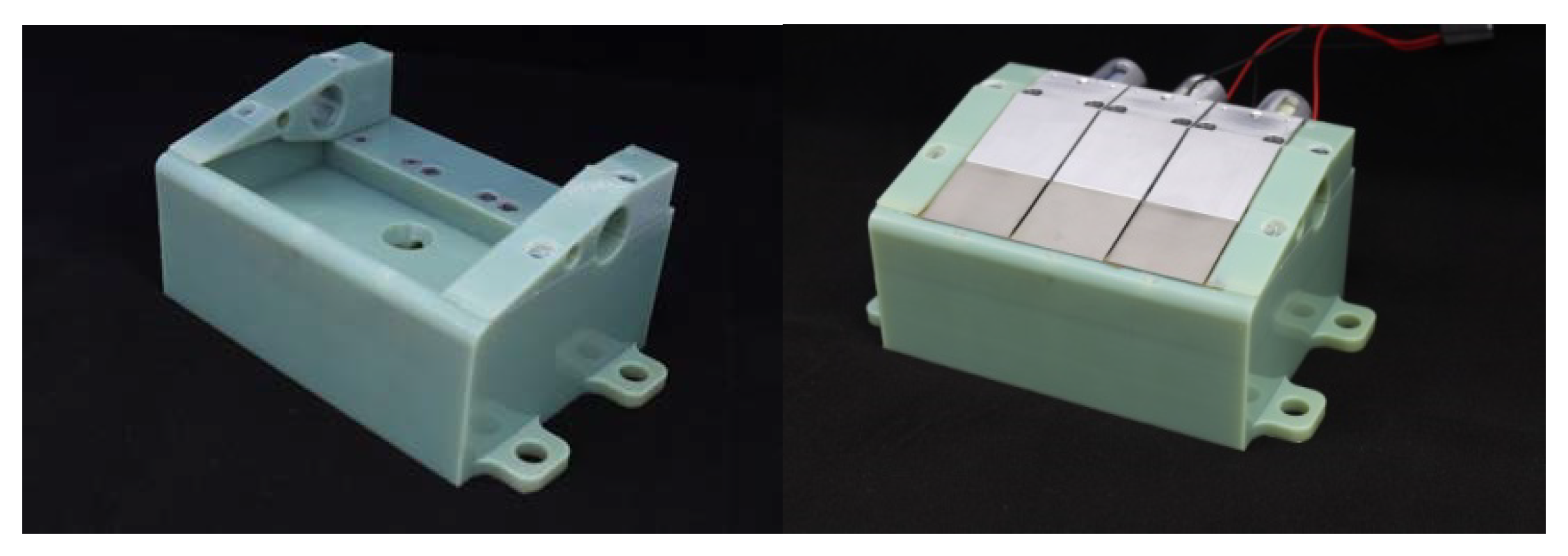
Furthermore, the precision when installing the lip segments can be improved by combining several aluminum bodies (see
Figure 7b) into larger modules. In principle, such a module could cover the entire span of the model. However, the production of such a module would be very complex, so that it makes sense to divide it into three modules, each of which can accommodate 11 lip segments. As a result, only three larger components would have to be installed and aligned in the wind tunnel model.
With the implementation of these enhancements, significantly improved results for future wind tunnel tests are expected.


