Article

On the Design of Aeroelastically Scaled Models of High Aspect-Ratio Wings

1
IDMEC, Instituto Superior Técnico, Universidade de Lisboa, 1049-001 Lisboa, Portugal
2
Instituto Superior Técnico, Universidade de Lisboa, 1049-001 Lisboa, Portugal
3
Department of Mechanical Engineering, University of Victoria, PO Box 1700, Stn. CSC, Victoria, BC V8W 2Y2, Canada
*
Author to whom correspondence should be addressed.
Aerospace 2020, 7(11), 166; https://doi.org/10.3390/aerospace7110166
Submission received: 6 October 2020 / Revised: 13 November 2020 / Accepted: 16 November 2020 / Published: 18 November 2020
(This article belongs to the Special Issue Aeroelasticity, Volume II)

Abstract

:
Recently, innovative aircraft designs were proposed to improve aerodynamic performance. Examples include high aspect ratio wings to reduce the aerodynamic induced drag to achieve lower fuel consumption. Such solution when combined with a lightweight structure may lead to aeroelastic instabilities such as flutter at lower air speeds compared to more conventional wing designs. Therefore, in order to ensure safe flight operation, it is important to study the aeroelastic behavior of the wing throughout the flight envelope. This can be achieved by either experimental or computational work. Experimental wind tunnel and scaled flight test models need to exhibit similar aeroelastic behavior to the full scale air vehicle. In this paper, three different aeroelastic scaling strategies are formulated and applied to a flexible high aspect-ratio wing. These scaling strategies are first evaluated in terms of their ability to generate reduced models with the intended representations of the aerodynamic, structural and inertial characteristics. Next, they are assessed in terms of their potential in representing the unsteady non-linear aeroelastic behavior in three different flight conditions. The scaled models engineered by exactly scaling down the internal structure suitably represent the intended aeroelastic behavior and allow the performance assessment for the entire flight envelope. However, since both the flight and wind tunnel models are constrained by physical and budgetary limitations, custom built structural models are more likely to be selected. However, the latter ones are less promising to study the entire flight envelope.

1. Introduction

One of the design solutions for improving the aerodynamic performance of commercial jetliners is to increase the aspect-ratio of the wing such that a reduction in the induced drag is obtained. Aspect-ratio increase is usually achieved by a compromise in chord reduction and span increase that enables aerodynamic advantages at typical operating conditions, namely in cruise and high g’s maneuvers, without a severe increase of the structural weight. This design solution has however an impact on the wing’s structure which is now more prone to higher deflections and root bending moments with the increase of wing span, which may result in geometric nonlinearities [1,2,3,4,5,6,7,8,9]. Hazardous aeroelastic phenomena such as flutter may arise from this higher flexibility in the flight envelope. Hence, the importance of studying aircraft aeroelastic behavior computationally and devising sub-scale models that are representative of the aeroelastic behavior of full size wing designs to enable the study of these new designs [10,11,12].
The topic of aeroelastic scaling is not new and significant efforts were made over recent decades. In fact, there are recent survey papers that cover the efforts carried out in aeroelastic scaling, but in general their focus are in broader subjects such as structural engineering [13,14] or aerodynamics [15]. Coutinho et al. [13] have presented an overview of the efforts done to build reduced scale models for structural engineering applications up to 2015. The recent paper from Casaburo et al. [14] which covers the main similitude methods for structural engineering, where simple and complex structures from different engineering fields are discussed, expands the previous revision paper. In a more recent paper [15], the author surveys wind tunnel models designed by recurring to additive manufacturing technologies, including some aeroelastic models built to study steady and unsteady aeroelastic phenomena.
There are some papers wherein the goal is set at devising aeroelastically scaled models of high aspect-ratio wings to study their behavior in flight [16,17,18,19] or in wind tunnel [20,21,22]. In the vast majority of the research articles in aeroelastic scaling, optimization is used as a numerical tool to build sub-scale models with the same structural dynamic behavior as their full size counterpart [17,20,21,23,24,25,26,27]. To achieve this, some authors set as design variables the dimensions of a predefined sub-scale internal structure and in some case mass points with the goal of reaching the same stiffness and mass characteristics of the full scale model, which requires solving at each optimization iteration a modal analysis. The mass points are sometimes defined in a second optimization loop, which succeeds a first optimization problem set to match the stiffness properties, evaluated using a static analysis, such as in [17,24,27]. Different objective functions and constraints are defined to replicate the dynamic properties in the sub-scale models, such as static deflection to a prescribed load, natural frequencies and corresponding mode shape, reduced frequencies, overall mass, and flutter speed, among others. Recently, a methodology to evaluate and design dynamically scaled models was proposed based on approximate similitude [28].
Nevertheless, only a few of these papers aim at studying nonlinear aeroelastic phenomena [18,19,21,25,26,27]. In this current work, the authors present different aeroelastic scaling strategies, for devising flight or wind tunnel models, formulated using three different sets of primary quantities to evaluate their performance in replicating the same nonlinear aeroelastic behavior of a full scale high aspect-ratio wing for different conditions in the flight envelope. This performance assessment is done and discussed in light of geometric, aerodynamic, structural, inertial, and aeroelastic (nonlinear unsteady response for three flight conditions) characteristics.

2. Methodology

The methodology section is organized as follows: (a) first the scaling strategies required to ensure aeroelastic similarity between full and scaled models are presented and discussed; (b) then the aeroelastic scaling methodology employed in this work is summarized; (c) and finally the aeroelastic framework is briefly introduced.

2.1. Aeroelastic Scaling

To aeroelastically scale a given model and before establishing scaling factors, one has to choose a set of three primary quantities encompassing mass, length and time. This choice has an impact on how well the scaled model represents its full size counterpart and is normally conditioned by several factors, especially by the purpose of the scaled model itself (i.e., for wind tunnel or flight testing) and the available budget which will dictate among others the size, mass and airspeed of the model. A suitable aeroelastic scaling is attained when the reduced model, also known as sub-scale model, mimics the structural dynamic and unsteady aerodynamic behavior of the real size model as well as the coupling behavior of these disciplines, i.e., the aeroelastic behavior. The aeroelastic behavior can be written in terms of the vector of elastic degrees of freedom { x } as follows,
M { x ¨ } + C { x ˙ } + K { x } = A M { x ¨ } + A C { x ˙ } + A K { x } ,
where the left hand side terms are related to the structural dynamic behavior considering the mass M , damping C and stiffness K ; while in the right hand side the equivalent aerodynamic terms are represented, i.e., mass A M , damping A C and A K stiffness.
Herein, three different sets of primary quantities are investigated to evaluate their applicability in devising aeroelastically scaled models for high aspect-ratio wings:
1.
Density ( ρ ), Velocity (v) and Span (b);
2.
Frequency ( ω ), Mass (m) and Span (b);
3.
Pressure (p), Density ( ρ ) and Span (b).
The first set is a common choice for devising flight test models since normally size, engine power and air properties choices are very limited, although it can also be used for designing aeroelastically scaled wind tunnel models. Values for the primary quantities of Set 2 have to be carefully selected such that it does not result in infeasible air properties. Set 3 can be seen as a promising option if the size of the model allows for manufacturing an exact scale down of the internal structure since the same material can be selected (given that these primary quantities have units of pressure and density).
After establishing a set of primary quantities, the Buckingham’s Π theorem [29] can then be applied to derive other relevant physical parameters by means of scaling factors (k). Length, time (t), frequency, mass, density, velocity, pressure, force (F), moment (M); and inertia (I) parameters are summarized in Table 1. The scaling factors are the result of the application of this theorem and are essential to derive the target parameters that the sub-scale model should match. The scaling factors directly associated with the primary quantities of each set, also known as independent scaling factors, are shaded and the subscripts s and r denote scaled and real size models, respectively.
These scaling factors should ensure both aerodynamic and dynamic similarities besides the obvious geometric similarity. The latter is achieved in all three sets.
Starting with aerodynamic similarity, despite the external geometry being the same it is difficult to completely achieve this similarity since both Reynolds ( R e ) and Mach ( M a ) numbers are not necessarily maintained. The task of matching these two dimensionless numbers in an aeroelastically scaled model is deemed very difficult and it is normally not done; it usually requires a compromise between model size (mass and length) and air properties (namely its density and temperature) which is usually not possible, especially if flight testing is sought. This shortcoming has influence on the viscous (Reynolds) and compressibility effects (Mach) of the scaled model. Sometimes roughness in added to the scaled model to induce separation at the same location of the full size computational model [30]. Nevertheless, accordingly to Pittit et al. [31] the Reynolds number is generally of minor importance for evaluating aeroelastic effects on main wings, as will be the case in study here; and accordingly to Ricciardi et al. [25] the Mach number is also assumed to present a small influence. Mach number similarity is enabled with Set 3, which might be useful if one desires to evaluate possible shock wave variation on the wing induced by the aeroelastic behavior, although this would be very difficult to achieve in a sub-scale flight test model. Therefore, in this work the similarity of both Reynolds and Mach numbers is set as a desirable goal, but not essential.
In what concerns the dynamic behavior, its similarity, also known as dynamic scaling, is reached when the target modal parameters, i.e., natural frequencies and associated mode shapes and damping ratios, are matched. In the case of exactly scaling the internal structure and using the same material, this similarity is automatically attained; however, since it is not often the case, for instance due to manufacturability issues, an optimization problem is normally employed to design a structure that can match the first target natural frequencies and associated mode shapes with those of the real model. Damping ratios are more difficult to account for in computational models and due to this reason they are rarely used and will not be considered in this work.
There are several strategies to dynamically scale a model resorting to optimization and starting with a simplified internal structure, as recommended by Bisplinghoff et al. [32], such as those presented in [17,18,25,27], but in this work only the method depicted in Figure 1 from [27] is used, but with different objective function and constraints established.
A generic problem statement for the scaling methodology selected can be formulated as follows,
minimize 1 N i = 1 N f i ( x ) f i t 2 + 1 N 1 N i = 1 N j = 1 N MAC i , j ( x ) MAC i , j t 2 with respect to x subject to ( f i ( x ) f i t ) / f i t 0.05 0 with i = 1 : N ( m ( x ) m t ) / m t 0.05 0 ( I i , j ( x ) I i , j t ) / I i , j t 0.05 0 with i = 1 : 3 and j = 1 : 3 ,
where f i is the ith natural frequency of the structure; N is the number of mode shapes to match; superscript t denotes target value for the given parameter; m and I represent the overall mass and the inertia tensor of the structure, respectively; x is a set of design variables; and MAC is the Modal Assurance Criterium matrix, which is a metric to evaluate how two different sets of mode shapes, in this case the target and the obtained ones, are correlated:
MAC = ϕ T × ϕ t ϕ T × ϕ ϕ t T × ϕ t ,
where ϕ is a matrix with a set of mode shapes. To avoid nomenclature misunderstanding, t referring to target is now a subscript since T denotes transpose. Two different sets of mode shapes are said to be perfectly correlated when the MAC matrix is an identity matrix.
The optimization problem (Equation (2)) is posed differently to that from [27] where direct mode matching was preferred instead of MAC in the objective function definition and the inertia tensor of the structure was added to the set of constraints. The former was chosen to improve numerical performance, while the latter accounts for the inertial properties, which is expected to be more relevant when flexibility effects are higher in the scaled model, which is the case of high aspect-ratio wings.
Other dimensionless parameters that should be kept in the scaled model are the reduced frequencies ( κ ) and the Froude number ( F r ). Reduced frequencies are computed for a given airspeed considering the natural frequencies and the wing span:
κ = f b v .
Froude number accordingly to Wan and Cesnik [19] should be matched to ensure similarity when flexibility effects are relevant to be analyzed in the devised model; this parameter is given as follows:
F r = v b g ,
where g is the acceleration of gravity.

2.2. Methodology

The following methodology was the one applied in this work:
1.
Build a full size wing model in the aeroelastic framework and run time domain simulations for three flight conditions (cruise, hold and alternate);
2.
Derive the scaling factors and the resulting target parameters to be matched by the sub-scale models, considering 3 different sets of primary quantities;
3.
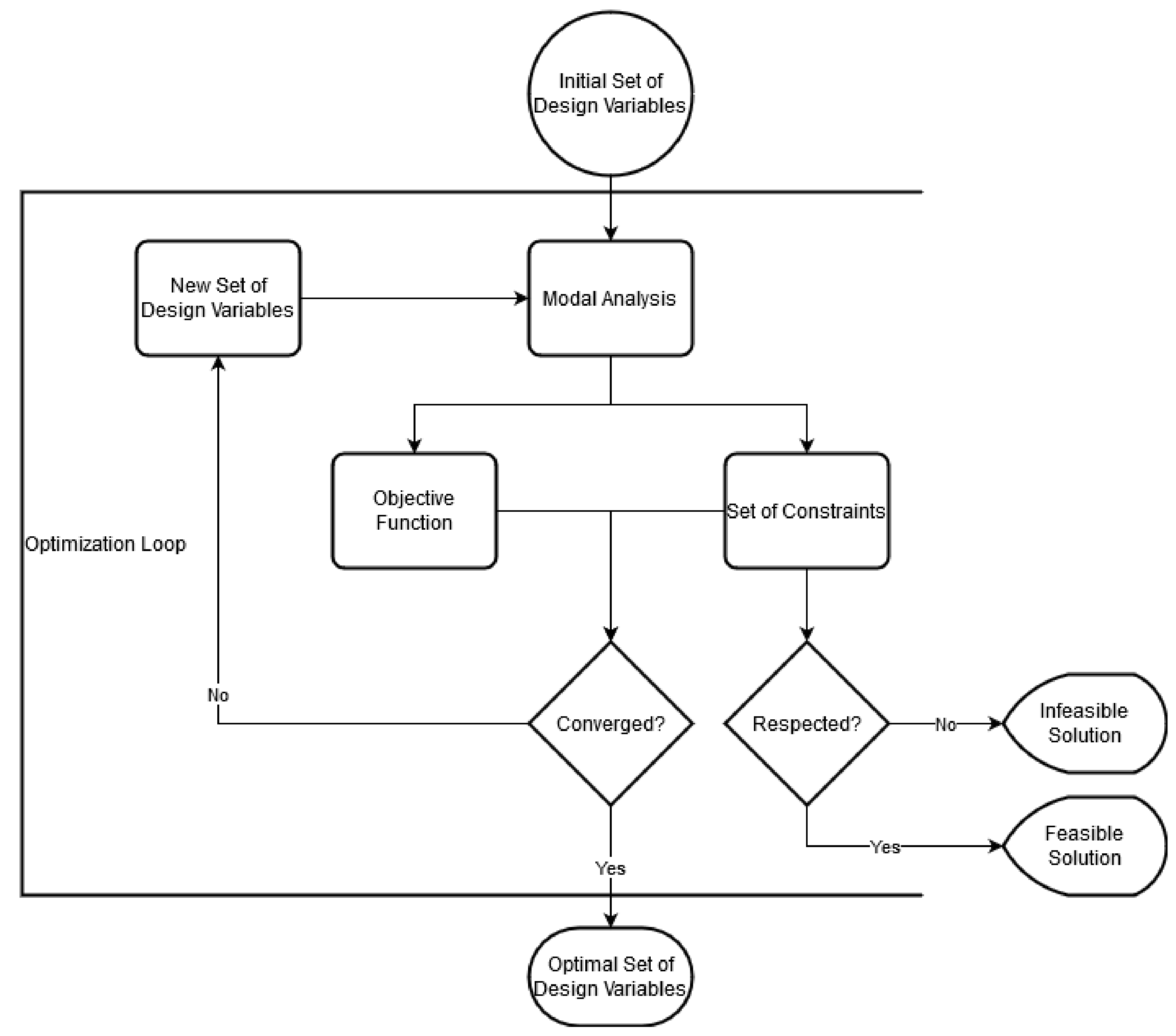
Apply a scaling methodology resorting to optimization with the aim at reaching the same dynamic scaling of the full size wing model;
4.
Run nonlinear unsteady simulations to predict the nonlinear aeroelastic response of the 3 scaled models and compare with the responses estimated for the initial wing model, i.e., the target responses for cruise, hold and alternate flight conditions.

2.3. Aeroelastic Framework

An in-house nonlinear aeroelastic framework described in [33,34] was used in this work. This framework is capable of analyzing flexibility effects on high aspect-ratio wings in the time domain considering both constrained, i.e., simulating wind tunnel conditions, and unconstrained i.e., emulating free-flight conditions, models. For this task, the code was enabled with a Fluid-Structure Interaction (FSI) algorithm responsible for coupling the structural and aerodynamic models by recurring to a loosely coupled scheme (where despite fluid and structure models being solved separately, the solution only advances in time when convergence between fluid and structure models is reached) that ensures consistency, but not energy conservation. Despite the use of low-medium fidelity aerodynamic (3D panel method with viscous and compressibility corrections) and structural (3D condensed beam model based on wing-box mass and inertia calculations) models, their applicability to preliminary design is adequate since they capture the main physical phenomena and allow exploring the design space [35,36]. The aerodynamic, structural and aeroelastic models were benchmarked [33,34] with existing data available in the literature. Furthermore, the application of this framework to estimate the aeroelastic behavior of both full and reduced size models ensures comparability between these models. Another feature available is the optimization capability [37], which for this work is necessary to design the structure of the sub-scale models such that it ensures dynamic similarity (i.e., to solve Equation (2)).

3. Wing Model

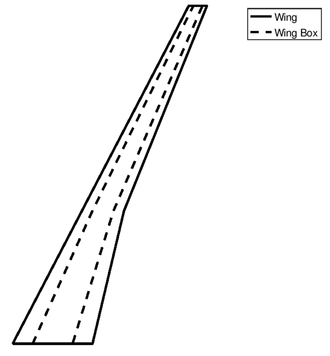
3.1. Full Size Model

For the wing model, such as in [27], a modified version of the main wing of the NOVEMOR project [38] was employed, but with an even higher aspect-ratio. The unmodified wing with an aspect-ratio and area of 9 and 110 m 2 , respectively, was stretched to increase the aspect-ratio to 16. For this task, the wing area and the angles of leading edge sweep and dihedral were kept unchanged, while the planform was altered by increasing the span and reducing the chord in a proportional way, i.e., indexed to the original span and mean aerodynamic chord. This geometrical modification combined with the chosen internal layout allows the wing to already present flexibility effects during normal operating conditions (e.g., at cruise). A simplified aluminum made wing box (with density of 2700 kg/m 3 , Young’s modulus of 70 GPa and Poisson’s ratio of 0.33) comprised between 25 and 75% of the local chord along the entire span was defined as the internal structure and the thicknesses of the spars and skins were assumed uniformed with values of 28 mm and 5.6 mm, respectively. This is an assumption made for this work. A different thickness distribution along the wingspan could have been made for the spar and skin, as well as a different material. However, the applicability of the scaling strategies here applied would not change. Only the inertial properties of the wing model would change and as a consequence the structural and aeroelastic behavior would also change, thus resulting in different target values for the scaled models to match. The main geometric characteristics of the modified wing are presented in Table 2 and its planform depicted in Figure 2.
Before proceeding with the scaling of this full size wing model, nonlinear aeroelastic time domain responses are estimated considering the already mentioned three different flight conditions: cruise; hold; and alternate (see Table 3). To obtain the unsteady aeroelastic responses for each of these flight conditions, the aeroelastic framework above mentioned was employed. The computational models for the aerodynamics and structures were defined based on a convergence study and have the following characteristics: an aerodynamic mesh built with an uniform distribution in the span direction (28 divisions), a cosine distribution in the chord direction (divisions) and an uniform wake of 100 chords length; structural mesh composed of 50 equally spaced nonlinear 3D beam finite elements. In the aeroelastic model the wing was set to be constrained at its root and the simulations start from an undeformed state; then the wing model is released into a constant airflow corresponding to the chosen flight condition, thus emulating a wind tunnel model with a sudden wind on condition. Despite this choice to estimate the aeroelastic response of both full and reduced models, the initial conditions could have been changed to simulate a flight test condition.

3.2. Reduced Scale Models

The definition of each primary quantity value for each Set to design aeroelastically scaled models was mainly based on having a wing semi-span large enough to accommodate the internal structure and the necessary instrumentation for flight testing, but not larger than 2.5 m to disable its testing on some closed-loop wind tunnel facilities; utilizing a material that potentiates the usage of 3D printing technology for building cheaper but yet complex geometries [39,40] when a direct scale down of the geometry is not possible; and enabling flight or wind tunnel testing.
Based on the above rational, a length scale of 1/10th resulting in a wing semi-span lower than 2.2 m was selected for all the analyzed sets of primary quantities; aluminum and nylon (Young’s modulus of 1.27 GPa, shear modulus of 0.3 GPa and density of 1010 kg/m 3 ) materials were selected for Sets 3 and Sets 1 and 2, respectively. For Sets 2 and 3 the air density and speed were obtained by the application of the scaling factor, although for Set 1 they were set to 1.225 kg/m 3 and 50 m/s, respectively, since it is possible to choose them in this Set. Considering the choices of values for the primary quantities and the scaling factors derived from them (given in Table 4), the main geometric, aerodynamic and structural parameters for each reduced model can be determined. Both geometric and aerodynamic parameters are inputs for the design of the reduced size models, while the structural parameters will be set as targets to be obtained; these are summarized in Table 5, from which one can add some comments regarding similarities between sub-scale models and full size model:
  • Geometric similarity is achieved with all the Sets of primary quantities at an external level, while only Set 3 provides internal geometric similarity due to the possibility of manufacturing the wing box structure using the same material (with thickness of 2.8 mm and 0.56 mm);
  • Reynolds number is not matched using any of the Sets of primary quantities (Set 3 is the one that is closest to the full size model) which means that the viscous effects will not be sufficiently represented in the sub-scale models, especially for the Set 2 for which a low Reynolds number was derived; as mentioned before Reynolds number is not considered to be of major importance for aeroelastic problems on the wing [31], although if deemed important for a given flight condition skin roughness can be changed to induce transition to turbulent flow as suggested in [30];
  • Compressibility effects will only be accurately represented when using Set 3; it is worth noting that the interaction between viscous and compressibility effects, if exists, will not be adequately captured since Reynolds number is not matched;
  • Dynamic similarity is immediately achieved by using Set 3 of primary quantities, because besides geometric similarity being possible both pressure and density are selected as primary quantities which enables the usage of the same material as in the full size model;
  • Froude number similarity is another similarity parameter that is not achieved with any of the Sets of primary quantities, although Set 2 provides the closest value.
Overall mass and inertia moments are set as targets to be matched in the structural design of the scaled models to reinforce the need to account for flexibility effects, due to the slenderness characteristic of high aspect-ratio wings.

4. Results

4.1. Aeroelastic Scaling

The previous section sets the targets to be met in the structural design of the sub-scale models. These targets, i.e., natural frequencies, correlation between mode shapes, overall mass and inertia moments compose the objective function and set of constraints of the optimization problem to be solved (Equation (2)) for each set of primary quantities. The selected design variables are related to the wing box characteristics: thickness of the leading and trailing edge spars at root, break and tip sections (linear interpolation is considered between sections); thickness of the wing skin, assumed uniformed, at root, break and tip sections (again linear interpolation is considered between sections); initial and final local chord positions of the wing box at each section (root, break and tip). A total of 15 design variables (x in Equation (2)) are thus used to design the internal structure of the sub-scale models.
Starting with Set 1, for which span, density and velocity were established as primary quantities, both aerodynamics and structural results are far from the defined target values, as one can notice from Table 6. It is worth recalling that the target values are obtained by applying the scaling factors of Table 4 to the corresponding parameter and set. Regarding aerodynamics, the lower velocity ( v = 50 m/s set for cruise) and the smaller scale (10 times smaller when compared with the full size model) have dictated the reduction of the Mach and Reynolds numbers with consequences on the aerodynamic coefficients (lift, drag and pitch moment), specially for the faster flight conditions, where compressibility effects have more influence as expected. Another aerodynamic problem with this Set of primary quantities is related to the exploration of the flight envelope: if we define, as we did for cruise, the speed and air density at 50 m/s and sea level conditions, respectively, for the remaining conditions (alternate and hold) the air densities will be higher which will be very difficult to achieve in a flight testing campaign, despite the lower speeds. Thus, this Set might only be appropriate for evaluating aeroelastic behavior for a given flight condition. In what concerns the structure, the different characteristics of the materials between full and scaled models combined with a relatively simple structural layout and a low number of design variables have not allowed achieving the same structural dynamic behavior, despite the relative differences between full and scaled models inertial properties being lower than 12.4%. If one computes the reduced frequencies, they will also be far from the ones calculated for the full size model. From the authors experience [27] with this Set it should be possible to improve the structural dynamic behavior with a higher number of design variables and recurring to mass points to tune the sub-scale model.
The selection of frequency and mass primary quantities in Set 2 has allowed for scaling the material properties from aluminum to nylon, by means of manipulating material density and Young’s modulus relations through density and pressure scaling factors to establish mass and frequency scaling factors. This resulted in a close structural and inertial properties match to the target values, as one can observe from Table 7. An exception was the first torsion mode which depends on both the Young’s modulus and the Poisson’s ratio; this last property is not maintained hence the discrepancy that can be of relevant importance in the typical case of flutter occurring due to the coupling of bending and torsion modes. The reduced frequencies are closer (about 30% of relative difference) to those from the full size model, except again for the torsional reduced frequency which has a higher discrepancy (45% of relative difference). In what concerns aerodynamics, the same comment made for the application of Set 1 can be done to Set 2 with the aggravation of an even higher relative error for the Reynolds number, with consequences in its ineptitude to account for the existing viscous effects. As a consequence of setting density scaling factor considering only material properties, the resulting air densities for each flight condition are even lower than the ones from the full scale, for instance a density equivalent to 17,820 m of altitude is calculated. This means that for flight testing one has to fly at the equivalent altitude or using lighter gases than air in a wind tunnel facility. Both options seem expensive.
With Set 3, for which no optimization problem was needed, the inertial and structural properties, including the reduced frequencies, of the scaled model are the same as the target ones (see Table 8). When looking at the aerodynamic results, one can notice that the Mach number similarity has allowed for errors lower than 1% for lift and pitch moments coefficients. The exception was the drag coefficient which has a higher difference from the target one, although it not as important in aeroelastic problems as the lift coefficient due to its lower value when compared with the latter. This discrepancy is explained by the Reynolds number that was not maintained, but is in fact 10 times lower due to the length scaling factor used to derive the scaled model. A note to the velocities and air densities which are the same as the ones from the full scale model, i.e., the same flight condition, thus requiring the model either to fly at high altitudes or to be tested in a transonic wind tunnel with a gas mixture lighter than air. Any of these options again might be expensive. Nevertheless, this Set seems the most adequate option for devising an aeroelastically scaled model if it is possible to manufacture an exactly scale down version of the internal structure recurring to the same material and to fly at the flight condition.

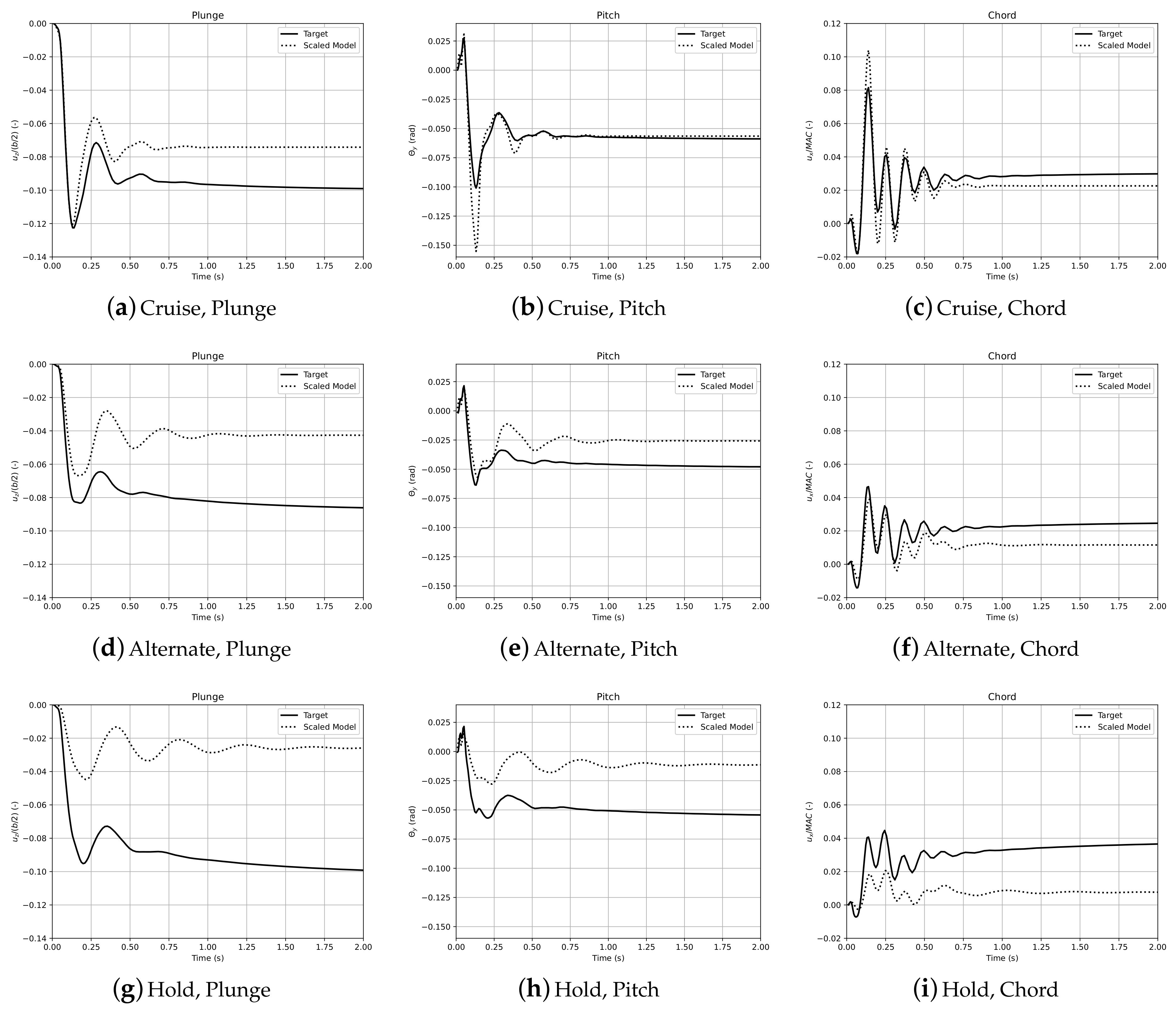
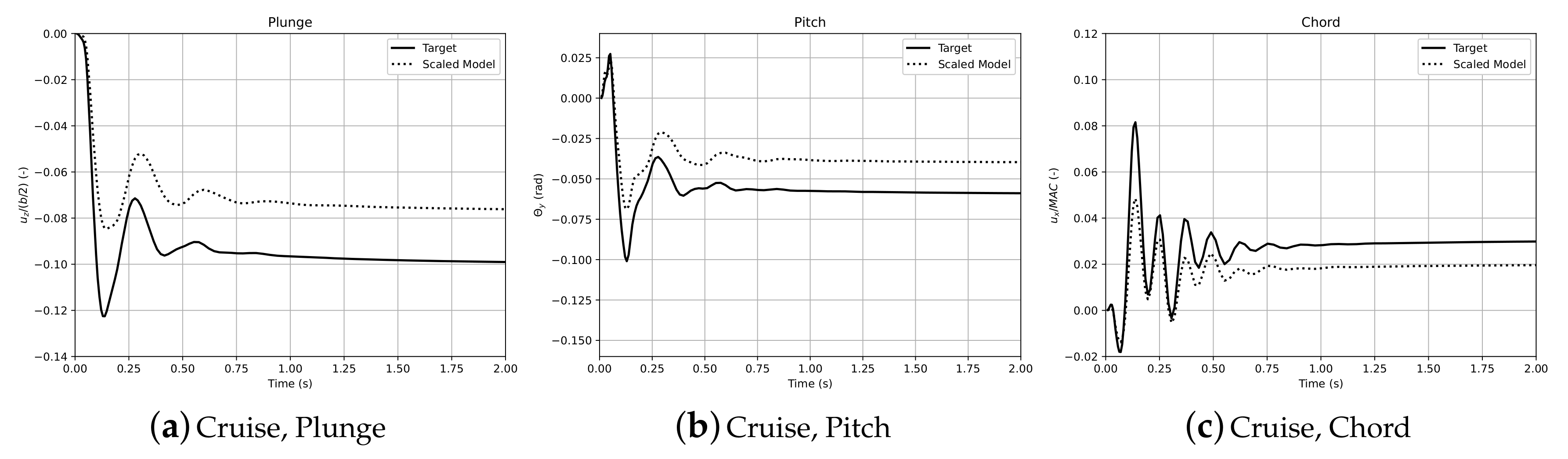
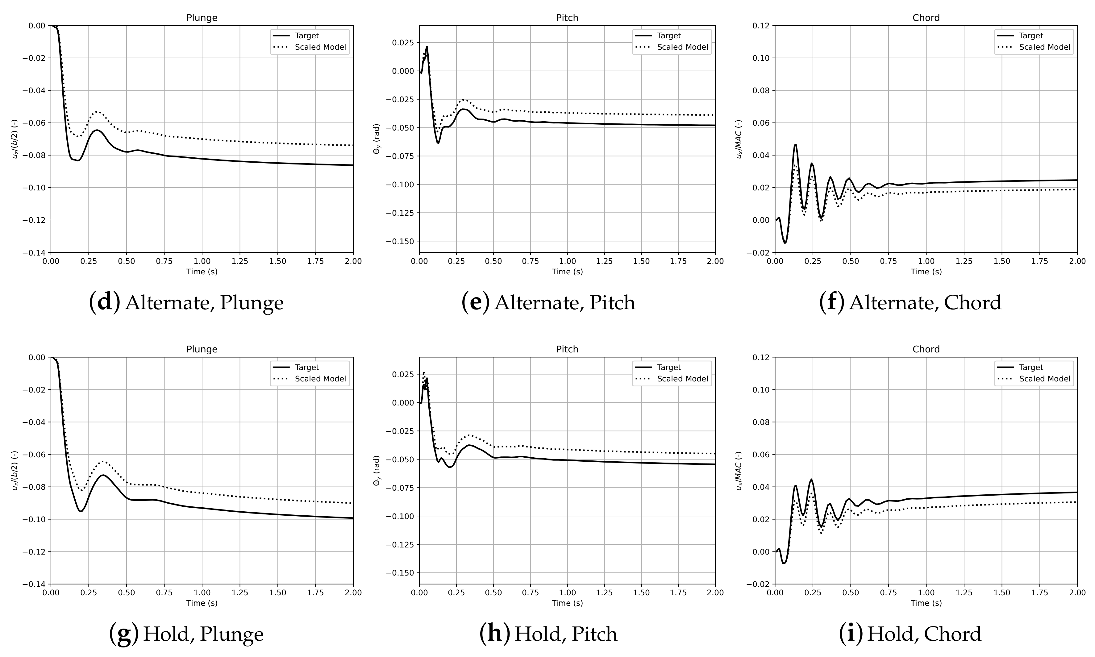
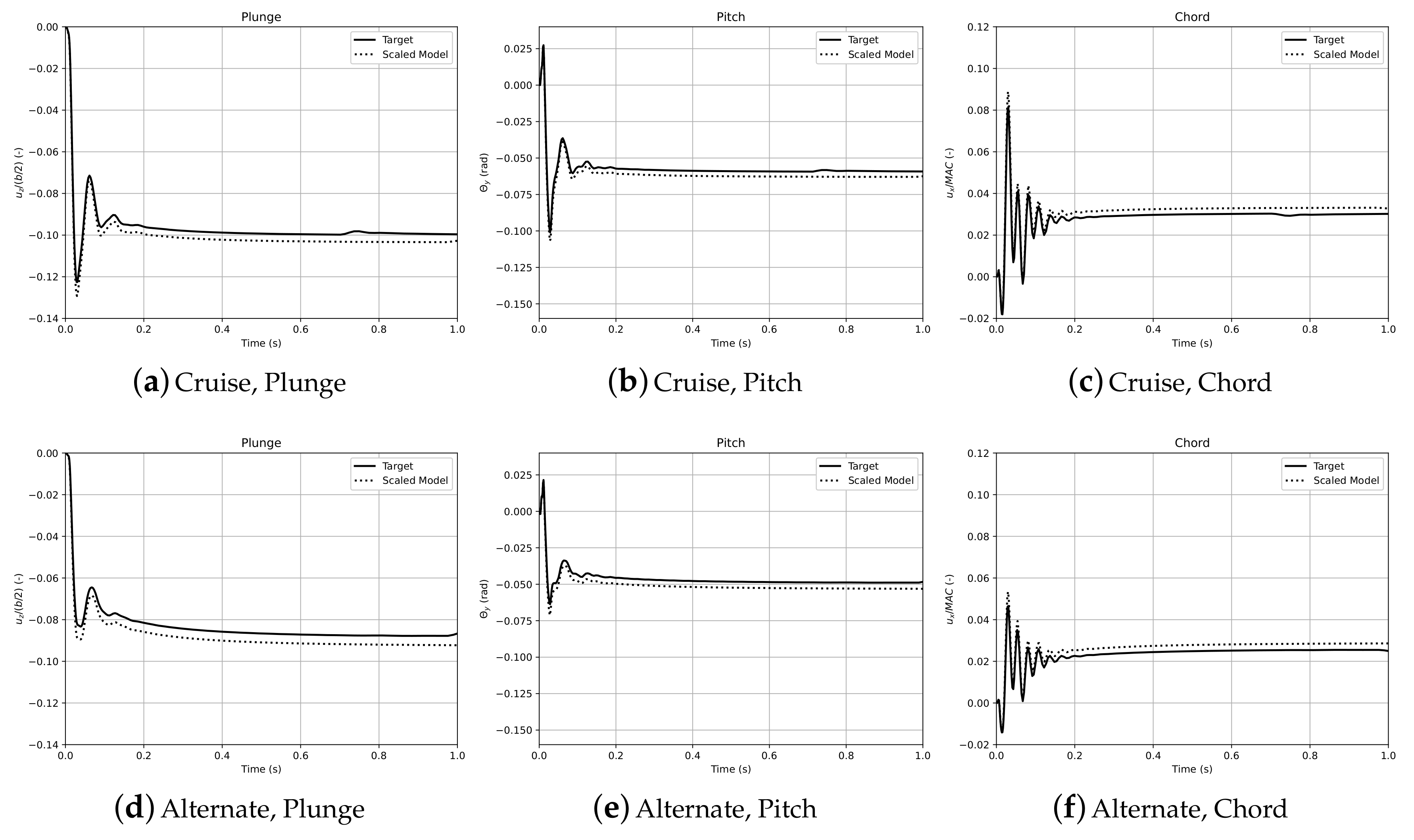
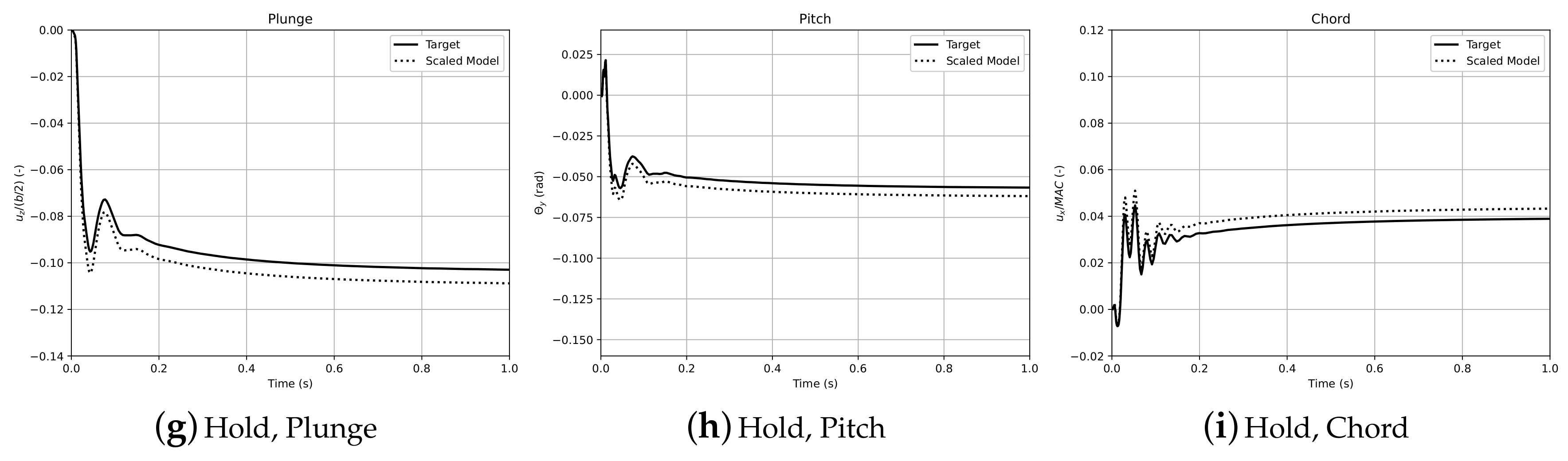
4.2. Aeroelastic Response

The nonlinear aeroelastic behavior of the reduced scaled models designed with the 3 different sets of primary quantities is now estimated in the time domain and compared with the one estimated for the full size model. As mentioned before, the wing model is constrained at its root and released into a constant flow corresponding to the desired flight condition. The response at the wing tip is measured in plunge (vertical motion of the wing), pitch (wing torsion) and chord (horizontal motion) degrees of freedom. To enable the comparison between full and reduced scale models, the plunge and chord degrees of freedom are divided by the wing’s semi-span and mean aerodynamic chord, respectively. A time step study was carried out using the full size wing for which a value of 0.01 s was selected in the end. The time step for the scaled models was estimated by applying the time scaling factor (corresponding to each Set) to the one used for the full scale model.
The poor matching of the aerodynamic and structural characteristics using Set 1 is clearly visible in the nonlinear aeroelastic response measured at the 3 degrees of freedom, for the 3 flight conditions, as shown in Figure 3. Similar trends are observed when the wing model is released into the constant airflow, although the behavior tends to get further apart from the full size model, especially for alternate and hold conditions.
A better correlation between full and scaled models can be observed for Set 2 in Figure 4 from the nonlinear aeroelastic responses, which seem to follow the same trends independently of the degree of freedom or the flight condition. However, the aeroelastic response of the scaled model is shifted (under estimated) when compared with the full model due to the discrepancies in the aerodynamic coefficients (which are lower for the scaled model).
As expected from the very good matching of aerodynamic, structural and inertial properties between full and scaled models using Set 3 (Table 7), the nonlinear aeroelastic responses given in Figure 5 for both models are very close with only small deviations. Since both the Mach number and the structural behavior are replicated in the scaled model for this particular case, the authors are led to believe that the source of slight deviation found in the aeroelastic behavior may be due to Reynolds number, given that it is 10 times lower in the scaled model. This issue can be mitigated as mentioned above if transition to turbulent flow is induced by means of skin roughness. The good agreement between aeroelastic responses independently of the flight conditions is a promising indication that this Set of primary quantities can be applied to devise aeroelastically scaled models, which can be tested throughout the flight envelope.

5. Concluding Remarks

Three different strategies to formulate aeroelastically scaled models, based on several combinations of primary variables, were studied and compared for their aerodynamic, structural, inertial, and aeroelastic characteristics for different flight conditions. The first two sets (1 and 2) of primary quantities require solving an optimization problem to design the internal structure of the scaled model that matches the structural dynamic behavior (and inertial properties) of the full scale model. Set 3 represents an exact geometric scaling of the internal structure using the same material and it allows to promptly define the scaled structure without resorting to costly optimization methods.
In terms of aerodynamics, both Sets 1 and 2 perform poorly since neither Mach number nor Reynolds number are reproduceable in the scaled models due to the lower velocities and geometric sizes, when compared with the full size model. Mach number is matched in Set 3 thus improving the aerodynamic similarity between full and reduced models, while the Reynolds number is not maintained. Regarding structural dynamics and inertial properties, Set 3 outperforms the other sets since the direct scale down with the same material as the full size model is carried out. For the structural model and corresponding design variables defined in this work, Set 2 yields better agreement in natural frequencies when compared to Set 1. The better overall similarity (aerodynamic, structural and inertial) of Set 3 was also noticed in the nonlinear aeroelastic response (plunge, pitch and chord degrees of freedom measured at the wing tip), where good agreement between full and sub-scale models is observed independently of the flight condition, thus showing its potential for exploring the entire flight envelope.
Looking at the feasibility of devising the scaled models, Set 1 leads to designs that are easier to build and cheaper to test in both flight and wind tunnel, while it may only be suitable for a small variation of the flight condition and not the entire flight envelope. Models scaled using Set 2 should be easy to build as well, but they will probably be much more expensive to test since they require low air densities. Set 3 clearly exhibits better results and allows for an exploration of the entire flight envelope, although the exactly scaled down internal structure may be larger than most closed-loop wind tunnel test sections to ensure manufacturability.
Finally, the scaling strategies presented can be improved using higher fidelity aeroelastic tools that enable the study of other nonlinear aeroelastic phenomena such as shock waves along the wing span.

Author Contributions

Conceptualization, F.A., F.L. and A.S.; methodology, F.A. and M.C.; software, F.A. and J.V.; validation, F.A., J.V., F.L. and A.S.; formal analysis, F.A. and M.C.; investigation, F.A. and M.C.; data curation, F.A. and M.C.; writing—original draft preparation, F.A.; writing—review and editing, F.L. and A.S.; visualization, F.A.; supervision, F.L. and A.S.; project administration, F.L.; funding acquisition, A.S. All authors have read and agreed to the published version of the manuscript.

Funding

The authors acknowledge Fundação para a Ciência e a Tecnologia (FCT), through IDMEC, under LAETA, project UIDB/50022/2020.

Conflicts of Interest

The authors declare no conflict of interest.

Nomenclature

The following nomenclature is used in this manuscript:
A C aerodynamic damping matrix
A K aerodynamic stiffness matrix
A M aerodynamic mass matrix
bwing span
C damping matrix
k M moment scaling factors
ffrequency
Fforce
FrFroude number
ggravity acceleration
Iinertia
kscaling factors
k F force scaling factors
k I inertia scaling factors
k l length scaling factors
k m mass scaling factors
k M moment scaling factors
k p pressure scaling factors
k t time scaling factors
k v velocity scaling factors
k ρ density scaling factors
k ω frequency scaling factors
K stiffness matrix
mmass
Mmoment
M mass matrix
MaMach number
MACModal Assurance Criteria
ppressure
ReReynolds number
ttime
vvelocity
xset of design variables
x vector of displacements
x ˙ vector of velocities
x ¨ vector of accelerations
κ reduced frequency
ρ density
ϕ matrix with a set of mode shapes
ω natural frequency

References

  1. Patil, M.; Hodges, D. On the importance of aerodynamic and structural geometrical nonlinearities in aeroelastic behavior of high-aspect-ratio wings. J. Fluids Struct. 2004, 19, 905–915. [Google Scholar] [CrossRef]
  2. Tang, D.; Dowell, E. Effects of geometric structural nonlinearity on flutter and limit cycle oscillations of high-aspect-ratio wings. J. Fluids Struct. 2004, 19, 291–306. [Google Scholar] [CrossRef]
  3. Cesnik, C.E.; Palacios, R.; Reichenbach, E.Y. Reexamined Structural Design Procedures for Very Flexible Aircraft. J. Aircr. 2014, 51, 1580–1591. [Google Scholar] [CrossRef] [Green Version]
  4. Tsushima, N.; Su, W. Flutter suppression for highly flexible wings using passive and active piezoelectric effects. Aerosp. Sci. Technol. 2017, 65, 78–89. [Google Scholar] [CrossRef]
  5. De Souza Siqueira Versiani, T.; Silvestre, F.J.; Guimarães Neto, A.B.; Rade, D.A.; Annes da Silva, R.G.; Donadon, M.V.; Bertolin, R.M.; Silva, G.C. Gust load alleviation in a flexible smart idealized wing. Aerosp. Sci. Technol. 2019, 86, 762–774. [Google Scholar] [CrossRef]
  6. Modaress-Aval, A.H.; Bakhtiari-Nejad, F.; Dowell, E.H.; Peters, D.A.; Shahverdi, H. A comparative study of nonlinear aeroelastic models for high aspect ratio wings. J. Fluids Struct. 2019, 85, 249–274. [Google Scholar] [CrossRef]
  7. Amato, E.; Polsinelli, C.; Cestino, E.; Frulla, G.; Joseph, N.; Carrese, R.; Marzocca, P. HALE wing experiments and computational models to predict nonlinear flutter and dynamic response. Aeronaut. J. 2019, 123, 912–946. [Google Scholar] [CrossRef]
  8. Cestino, E.; Frulla, G.; Spina, M.; Catelani, D.; Linari, M. Numerical simulation and experimental validation of slender wings flutter behaviour. Proc. Inst. Mech. Eng. Part G J. Aerosp. Eng. 2019, 233, 5913–5928. [Google Scholar] [CrossRef]
  9. Riso, C.; Ghadami, A.; Cesnik, C.E.S.; Epureanu, B.I. Data-Driven Forecasting of Postflutter Responses of Geometrically Nonlinear Wings. AIAA J. 2020, 58, 2726–2736. [Google Scholar] [CrossRef]
  10. Afonso, F.; Vale, J.; Oliveira, É.; Lau, F.; Suleman, A. A review on non-linear aeroelasticity of high aspect-ratio wings. Prog. Aerosp. Sci. 2017, 89, 40–57. [Google Scholar] [CrossRef]
  11. Jonsson, E.; Riso, C.; Lupp, C.A.; Cesnik, C.E.; Martins, J.R.; Epureanu, B.I. Flutter and post-flutter constraints in aircraft design optimization. Prog. Aerosp. Sci. 2019, 109, 100537. [Google Scholar] [CrossRef]
  12. Gao, C.; Zhang, W. Transonic aeroelasticity: A new perspective from the fluid mode. Prog. Aerosp. Sci. 2020, 113, 100596. [Google Scholar] [CrossRef] [Green Version]
  13. Coutinho, C.P.; Baptista, A.J.; Dias Rodrigues, J. Reduced scale models based on similitude theory: A review up to 2015. Eng. Struct. 2016, 119, 81–94. [Google Scholar] [CrossRef]
  14. Casaburo, A.; Petrone, G.; Franco, F.; De Rosa, S. A Review of Similitude Methods for Structural Engineering. Appl. Mech. Rev. 2019, 71, 030802. [Google Scholar] [CrossRef] [Green Version]
  15. Zhu, W. Models for wind tunnel tests based on additive manufacturing technology. Prog. Aerosp. Sci. 2019, 110, 100541. [Google Scholar] [CrossRef]
  16. Blair, M.; Garmann, D.; Canfield, R.; Bond, V.; Pereira, P.; Suleman, A. Non-Linear Aeroelastic Scaling of a Joined-Wing Concept. In Proceedings of the 48th AIAA/ASME/ASCE/AHS/ASC Structures, Structural Dynamics, and Materials Conference, Honolulu, HI, USA, 23–26 April 2007. [Google Scholar] [CrossRef]
  17. Richards, J.; Suleman, A. Aeroelastic scaling of unconventional joined wing concept for exploration of gust load response. In Proceedings of the International Forum on Aeroelasticity and Structural Dynamics IFASD, Seattle, WA, USA, 21–25 June 2009. [Google Scholar]
  18. Bond, V.L.; Canfield, R.A.; Suleman, A.; Blair, M. Aeroelastic Scaling of a Joined Wing for Nonlinear Geometric Stiffness. AIAA J. 2012, 50, 513–522. [Google Scholar] [CrossRef]
  19. Wan, Z.; Cesnik, C.E.S. Geometrically Nonlinear Aeroelastic Scaling for Very Flexible Aircraft. AIAA J. 2014, 52, 2251–2260. [Google Scholar] [CrossRef] [Green Version]
  20. Pereira, P.; Almeida, L.; Suleman, A.; Bond, V.; Canfield, R.; Blair, M. Aeroelastic scaling and optimization of a joined wing aircraft concept. In Proceedings of the 48th AIAA/ASME/ASCE/AHS/ASC Structures, Structural Dynamics, and Materials Conference, Honolulu, HI, USA, 23–26 April 2007. [Google Scholar] [CrossRef]
  21. Coelho, M.; Afonso, F.; Lau, F.; Suleman, A. Nonlinear aeroelastic scaling studies on high aspect ratio wings. In Proceedings of the 6th EASN International Conference on Innovation in European Aeronautics Research, Porto, Portugal, 18–21 October 2016. [Google Scholar]
  22. Yusuf, S.Y.; Hayes, D.; Pontillo, A.; Carrizales, M.A.; Dussart, G.X.; Lone, M.M. Aeroelastic Scaling for Flexible High Aspect Ratio Wings. In Proceedings of the AIAA Scitech 2019 Forum, San Diego, CA, USA, 7–11 January 2019. [Google Scholar] [CrossRef] [Green Version]
  23. French, M. An application of structural optimization in wind tunnel model design. In Proceedings of the 31st Structures, Structural Dynamics and Materials Conference, Long Beach, CA, USA, 2–4 April 1990. [Google Scholar] [CrossRef]
  24. French, M.; Eastep, F.E. Aeroelastic model design using parameter identification. J. Aircr. 1996, 33, 198–202. [Google Scholar] [CrossRef]
  25. Ricciardi, A.P.; Eger, C.A.G.; Canfield, R.A.; Patil, M.J. Nonlinear Aeroelastic-Scaled-Model Optimization Using Equivalent Static Loads. J. Aircr. 2014, 51, 1842–1851. [Google Scholar] [CrossRef]
  26. Ricciardi, A.P.; Canfield, R.A.; Patil, M.J.; Lindsley, N. Nonlinear Aeroelastic Scaled-Model Design. J. Aircr. 2016, 53, 20–32. [Google Scholar] [CrossRef]
  27. Spada, C.; Afonso, F.; Lau, F.; Suleman, A. Nonlinear aeroelastic scaling of high aspect-ratio wings. Aerosp. Sci. Technol. 2017, 63, 363–371. [Google Scholar] [CrossRef]
  28. Banazadeh, A.; Hajipouzadeh, P. Using approximate similitude to design dynamic similar models. Aerosp. Sci. Technol. 2019, 94, 105375. [Google Scholar] [CrossRef]
  29. Buckingham, E. On Physically Similar Systems; Illustrations of the Use of Dimensional Equations. Phys. Rev. 1914, 4, 345–376. [Google Scholar] [CrossRef]
  30. Ouellette, J.; Patil, M.; Kapania, R. Scaling Laws for Flight Control Development and Testing in the Presence of Aeroservoelastic Interactions. In Proceedings of the AIAA Atmospheric Flight Mechanics Conference, Minneapolis, MN, USA, 13–16 August 2012. [Google Scholar] [CrossRef]
  31. Pittit, C.L.; Canfield, R.A.; Ghanem, R.L. Stochastic analysis of a aeroelastic system. In Proceedings of the 15th ASCE Engineering Mechanics Conference, New York, NY, USA, 2–5 June 2002. [Google Scholar]
  32. Bisplinghoff, R.L.; Ashley, H.; Halfman, R.L. Aeroelasticity; Dover Publications: Mineola, NY, USA, 1996. [Google Scholar]
  33. Suleman, A.; Afonso, F.; Vale, J.; Oliveira, E.; Lau, F. Non-linear aeroelastic analysis in the time domain of high-aspect-ratio wings: Effect of chord and taper-ratio variation. Aeronaut. J. 2017, 121, 21–53. [Google Scholar] [CrossRef]
  34. Afonso, F.; Leal, G.; Vale, J.; Oliveira, E.; Lau, F.; Suleman, A. The effect of stiffness and geometric parameters on the nonlinear aeroelastic performance of high aspect ratio wings. Proc. Inst. Mech. Eng. Part G J. Aerosp. Eng. 2017, 231, 1824–1850. [Google Scholar] [CrossRef]
  35. Howcroft, C.; Neild, S.; Lowenberg, M.; Cooper, J. Efficient aeroelastic beam modelling and the selection of a structural shape basis. Int. J. Non-Linear Mech. 2019, 112, 73–84. [Google Scholar] [CrossRef] [Green Version]
  36. Rajpal, D.; Gillebaart, E.; De Breuker, R. Preliminary aeroelastic design of composite wings subjected to critical gust loads. Aerosp. Sci. Technol. 2019, 85, 96–112. [Google Scholar] [CrossRef]
  37. Afonso, F.; Vale, J.; Lau, F.; Suleman, A. Performance based multidisciplinary design optimization of morphing aircraft. Aerosp. Sci. Technol. 2017, 67, 1–12. [Google Scholar] [CrossRef]
  38. De Gaspari, A.; Ricci, S.; Antunes, A.; Odaguil, F.; Lima, G. Chapter 6-Expected Performances. In Morphing Wing Technologies; Concilio, A., Dimino, I., Lecce, L., Pecora, R., Eds.; Butterworth-Heinemann: Oxford, UK, 2018; pp. 175–203. [Google Scholar] [CrossRef]
  39. Ngo, T.D.; Kashani, A.; Imbalzano, G.; Nguyen, K.T.; Hui, D. Additive manufacturing (3D printing): A review of materials, methods, applications and challenges. Compos. Part B Eng. 2018, 143, 172–196. [Google Scholar] [CrossRef]
  40. Zhu, W.; Zhang, X.; Li, D. Flexible all-plastic aircraft models built by additive manufacturing for transonic wind tunnel tests. Aerosp. Sci. Technol. 2019, 84, 237–244. [Google Scholar] [CrossRef]
Figure 1. Scaling methodology.
Aerospace 07 00166 g001
Figure 2. Wing model.
Aerospace 07 00166 g002
Figure 3. Aeroelastic response measure at the wing tip for plunge, pitch and chord degrees of freedom for the reduced and target models, considering SET 1.
Aerospace 07 00166 g003
Figure 4. Aeroelastic response measure at the wing tip for plunge, pitch and chord degrees of freedom for the reduced and target models, considering SET 2.
Aerospace 07 00166 g004aAerospace 07 00166 g004b
Figure 5. Aeroelastic response measure at the wing tip for plunge, pitch and chord degrees of freedom for the reduced and target models, considering SET 3.
Aerospace 07 00166 g005aAerospace 07 00166 g005b
Table 1. Summary of the scaling factors for the 3 sets of primary quantities. The shaded cells correspond to the selected primary quantities in each set.
ParameterSet 1Set 2Set 3
Length, k l b s b r b s b r b s b r
Time, k t k l k v 1 k ω k ρ k l 2 k p
Frequency, k ω k v k l ω s ω r k p k ρ k l 2
Mass, k m k ρ k l 3 m s m r k ρ k l 3
Density, k ρ ρ s ρ r k m k l 3 ρ s ρ r
Velocity, k v v s v r k ω k l k p k ρ
Pressure, k p k ρ k v 2 k m k l 3 k ω 2 p s p r
Force, k F k ρ k v 2 k l 2 k m k l k ω 2 k p k l 2
Moment, k M k ρ k v 2 k l 3 k m k l 2 k ω 2 k p k l 3
Inertia, k I k ρ k l 5 k m k l 2 k ρ k l 5
Table 2. Main geometric characteristics of the modified wing.
CharacteristicValue
Area (m 2 )110
Aspect-ratio (-)16
Span (m)41.95
Mean Aerodynamic Chord (m)2.62
Root Chord (m)4.95
Inboard Wing Half Semi-span (m)8.24
Break Chord (m)2.61
Outboard Wing Half Semi-span (m)12.73
Tip Chord (m)1.13
Dihedral Angle (deg)4.4
Leading Edge Sweep Angle (deg)27.5
Table 3. Flight conditions.
CruiseHoldAlternate
Mach (-)0.780.50.3
Altitude (m)115825486610
Air density (kg/m 3 )0.3320.6981.155
Velocity (m/s)230159101
Trim lift coefficient (-)0.5880.5840.872
Trim angle of attack (deg)5.365.337.95
Table 4. Summary of the resulting scaling factors for the 3 sets of primary quantities. The shaded cells correspond to the primary quantities chosen for each set.
ParameterSet 1Set 2Set 3
Length, k l 0.10.10.1
Time, k t 0.46030.45410.1
Frequency, k ω 2.17252.202310
Mass, k m 0.00373.7407 × 10 4 0.001
Density, k ρ 10.37411
Velocity, k v 0.21720.22020.3162
Pressure, k p 0.17410.01811
Force, k F 0.00171.8143 × 10 4 0.01
Moment, k M 0.00021.8143 × 10 5 0.001
Inertia, k I 3.6899 × 10 5 3.7407 × 10 6 1.0 × 10 5
Table 5. Summary of the geometric, aerodynamic and structural parameters for the 3 sets of primary quantities.
ParameterFull-SizeSet 1Set 2Set 3
Wing semi-span (m)20.9752.09752.09752.975
Mean aerodynamic chord (m)2.620.2620.2620.262
Wing area (m 2 )1101.11.11.1
Air density (kg/m 3 )0.3321.2250.1240.332
Air speed (m/s)2305051230
Mach number (-)0.780.150.170.78
Reynolds number (-)13,987,9031,121,297115,2351,398,790
Trim lift coefficient (-)0.5880.5880.5880.588
Trim angle of attack (deg)5.365.365.365.36
Mass (kg)18746.9150.7011.874
I x x (kg.m 2 )183,3126.7640.6861.833
I y y (kg.m 2 )59,8382.2080.2240.598
I z z (kg.m 2 )240,1478.8610.8982.401
I x y (kg.m 2 )−100,368−3.704−0.375−1.004
I x z (kg.m 2 )89150.3290.0330.089
I y z (kg.m 2 )−16,459−0.607−0.062−0.165
Froude number (-)11.420.37.935.9
Table 6. Aerodynamics, structural and inertial results obtained using Set 1.
ParameterFull SizeTargetScaledDifference (%)
C L @ cruise (-)0.7790.7790.61421.2
C D @ cruise (-)0.0670.0670.01183.7
C M @ cruise (-)1.3051.3050.95426.9
C L @ alternate (-)0.6970.6970.60712.9
C D @ alternate (-)0.0140.0140.01124.2
C M @ alternate (-)1.0821.0820.94312.9
C L @ hold (-)0.8710.8710.8334.4
C D @ hold (-)0.0210.0210.01811.3
C M @ hold (-)1.3811.3811.3214.4
1st Flap (Hz)1.2632.7453.84540.2
2nd Flap (Hz)5.15511.19811.3211.1
1st Chord (Hz)5.22811.35711.6352.5
3rd Flap (Hz)11.67725.36823.1008.9
2nd Chord (Hz)20.90445.41424.03047.1
4th Flap (Hz)21.21146.08036.70520.4
1st Torsion (Hz)27.66060.09041.49530.9
5th Flap (Hz)34.25374.41245.93138.3
3rd Chord (Hz)47.553103.30865.91836.2
6th Flap (Hz)50.178109.00970.85135.0
Mass (kg)18746.9157.2815.3
I x x (kg.m 2 )183,3126.7646.01511.1
I y y (kg.m 2 )59,8382.2082.0089.1
I z z (kg.m 2 )240,1478.8617.92610.6
I x y (kg.m 2 )−100,368−3.704−3.30010.9
I x z (kg.m 2 )89150.3290.28812.4
I y z (kg.m 2 )−16,459−0.607−0.53611.8
Table 7. Aerodynamics, structural and inertial results obtained using Set 2.
ParameterFull sizeTargetScaledDifference (%)
C L @ cruise (-)0.7790.7790.62819.5
C D @ cruise (-)0.0670.0670.01479.1
C M @ cruise (-)1.3051.3050.97425.4
C L @ alternate (-)0.6970.6970.61411.9
C D @ alternate (-)0.0140.0140.0139.5
C M @ alternate (-)1.0821.0820.95312.0
C L @ hold (-)0.8710.8710.8364.0
C D @ hold (-)0.0210.0210.0195.7
C M @ hold (-)1.3811.3811.3264.0
1st Flap (Hz)1.2632.7842.7810.1
2nd Flap (Hz)5.15511.29511.3500.5
1st Chord (Hz)5.22811.49011.5030.1
3rd Flap (Hz)11.67725.62125.7100.4
2nd Chord (Hz)20.90445.78845.9880.4
4th Flap (Hz)21.21146.63046.6480.0
1st Torsion (Hz)27.66060.92147.82121.5
5th Flap (Hz)34.25375.15175.4290.4
3rd Chord (Hz)47.553104.341105.1470.8
6th Flap (Hz)50.178110.321110.6190.3
Mass (kg)18740.7010.7020.2
I x x (kg.m 2 )183,3120.6860.6870.1
I y y (kg.m 2 )59,8380.2240.2240.1
I z z (kg.m 2 )240,1470.8980.8990.1
I x y (kg.m 2 )−100,368−0.375−0.3760.1
I x z (kg.m 2 )89150.0330.0330.1
I y z (kg.m 2 )−16,459−0.062−0.0620.2
Table 8. Aerodynamics, structural and inertial results obtained using Set 3.
ParameterFull SizeTargetScaledDifference (%)
C L @ cruise (-)0.7790.7790.7790.0
C D @ cruise (-)0.0670.0670.0662.1
C M @ cruise (-)1.3051.3051.3050.4
C L @ alternate (-)0.6970.6970.6990.2
C D @ alternate (-)0.0140.0140.0136.1
C M @ alternate (-)1.0821.0821.0850.2
C L @ hold (-)0.8710.8710.8720.1
C D @ hold (-)0.0210.0210.0205.3
C M @ hold (-)1.3811.3811.3820.1
1st Flap (Hz)1.26312.64212.6420.0
2nd Flap (Hz)5.15551.28551.2850.0
1st Chord (Hz)5.22852.17452.1740.0
3rd Flap (Hz)11.677116.340116.3400.0
2nd Chord (Hz)20.904207.912207.9120.0
4th Flap (Hz)21.211211.734211.7340.0
1st Torsion (Hz)27.660276.627276.6620.0
5th Flap (Hz)34.253341.240341.2400.0
3rd Chord (Hz)47.553473.783473.7860.0
6th Flap (Hz)50.178500.939500.9420.0
Mass (kg)18741.8741.8740.0
I x x (kg.m 2 )183,3121.8331.8330.0
I y y (kg.m 2 )59,8380.5980.5980.0
I z z (kg.m 2 )240,1472.4012.4010.0
I x y (kg.m 2 )−100,368−1.004−1.0040.0
I x z (kg.m 2 )89150.0890.0890.0
I y z (kg.m 2 )−16,459−0.165−0.1650.0
Publisher’s Note: MDPI stays neutral with regard to jurisdictional claims in published maps and institutional affiliations.

