Development and Testing of Woven FRP Flexure Hinges for Pressure-Actuated Cellular Structures with Regard to Morphing Wing Applications

 , , , , and
Abstract
:
1. Introduction
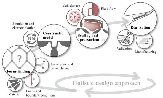
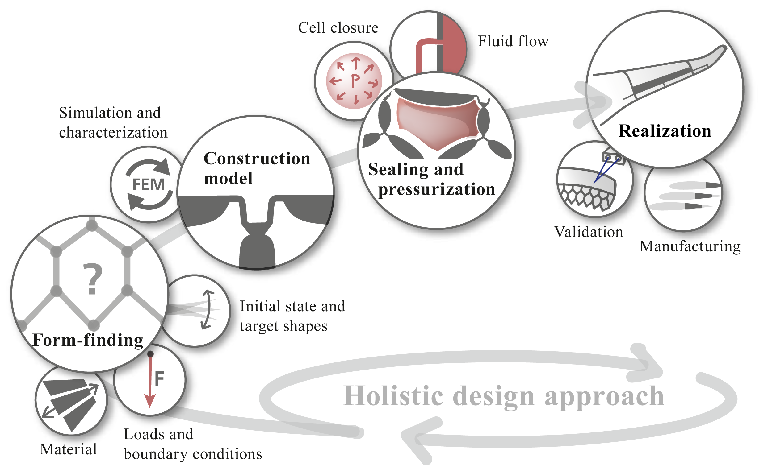
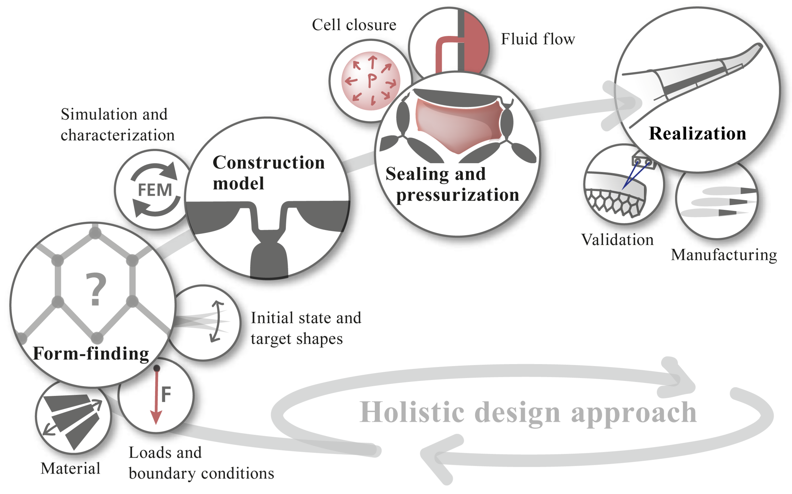
2. PACS—Concept and Approach
- the transfer into a 3D construction model,
- the fluid flow concept,
- the shape-variable cell closure,
- the manufacturing process, and
- the experimental proof of concept.
3. Materials and Methods
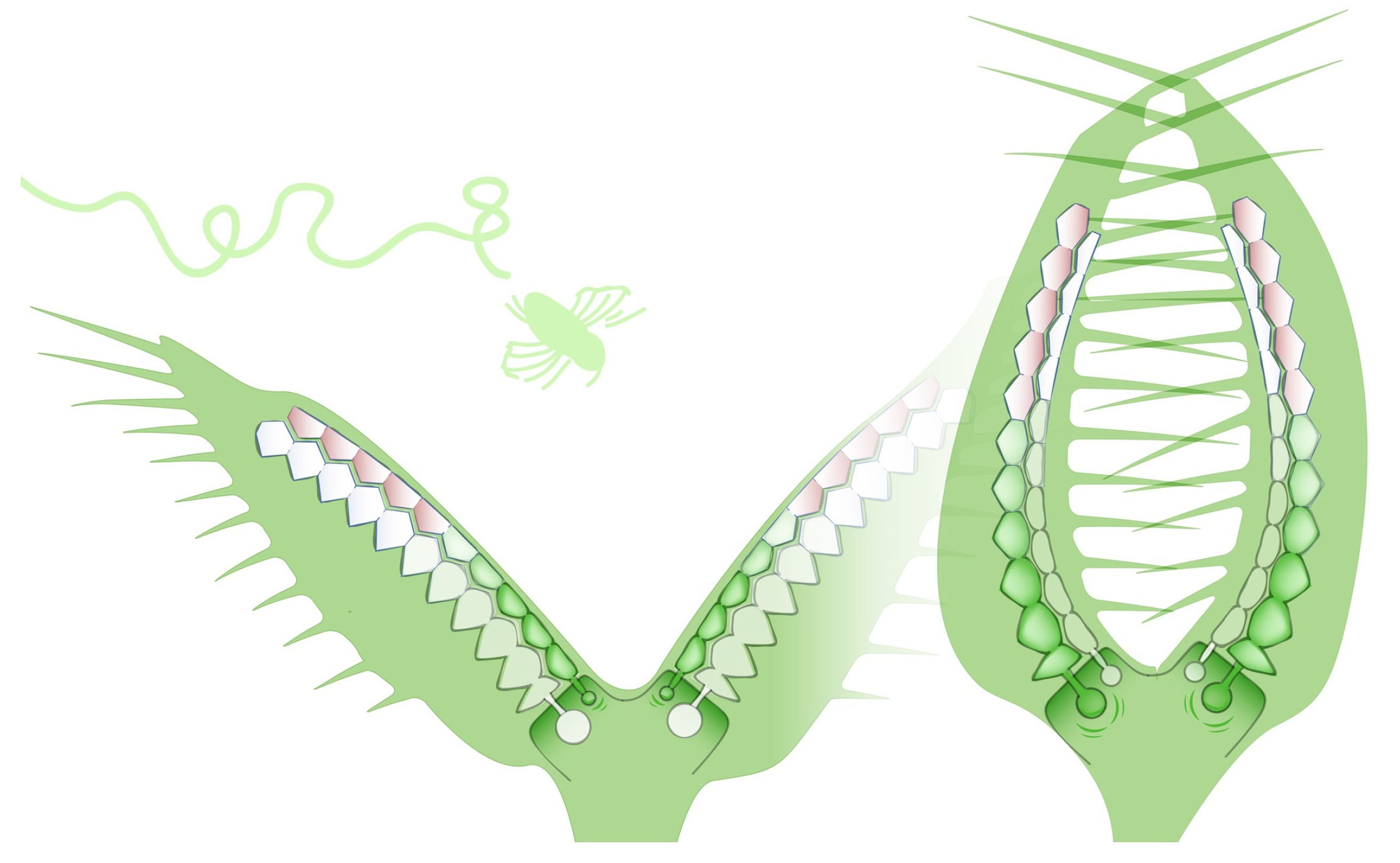
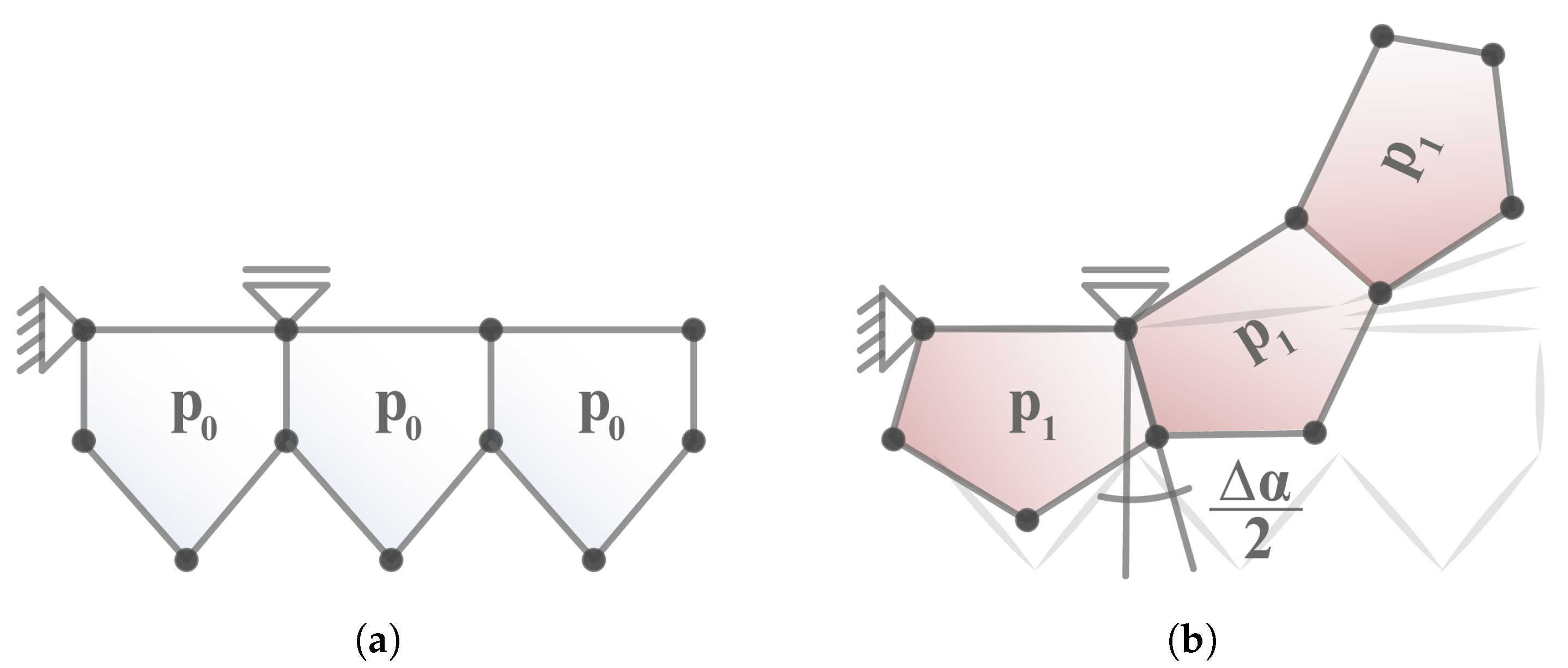
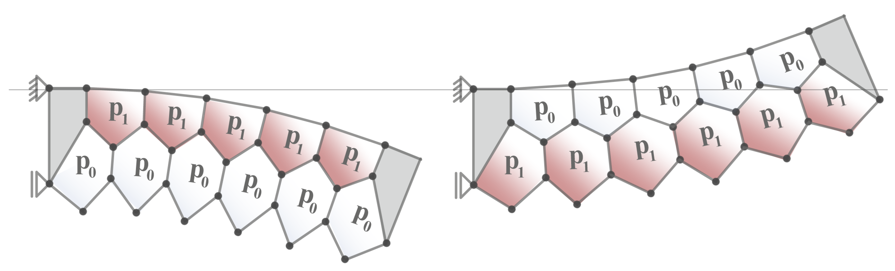
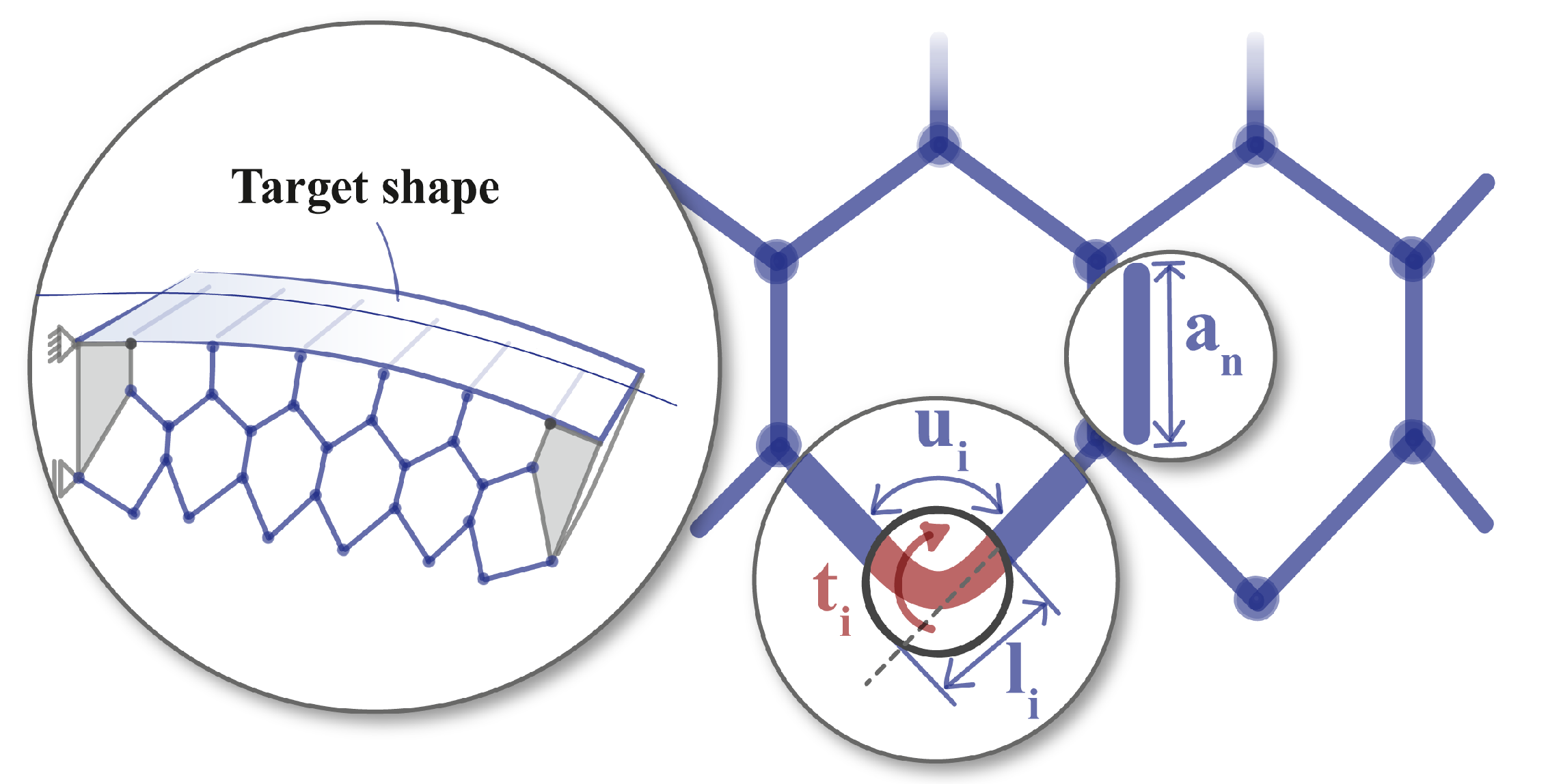
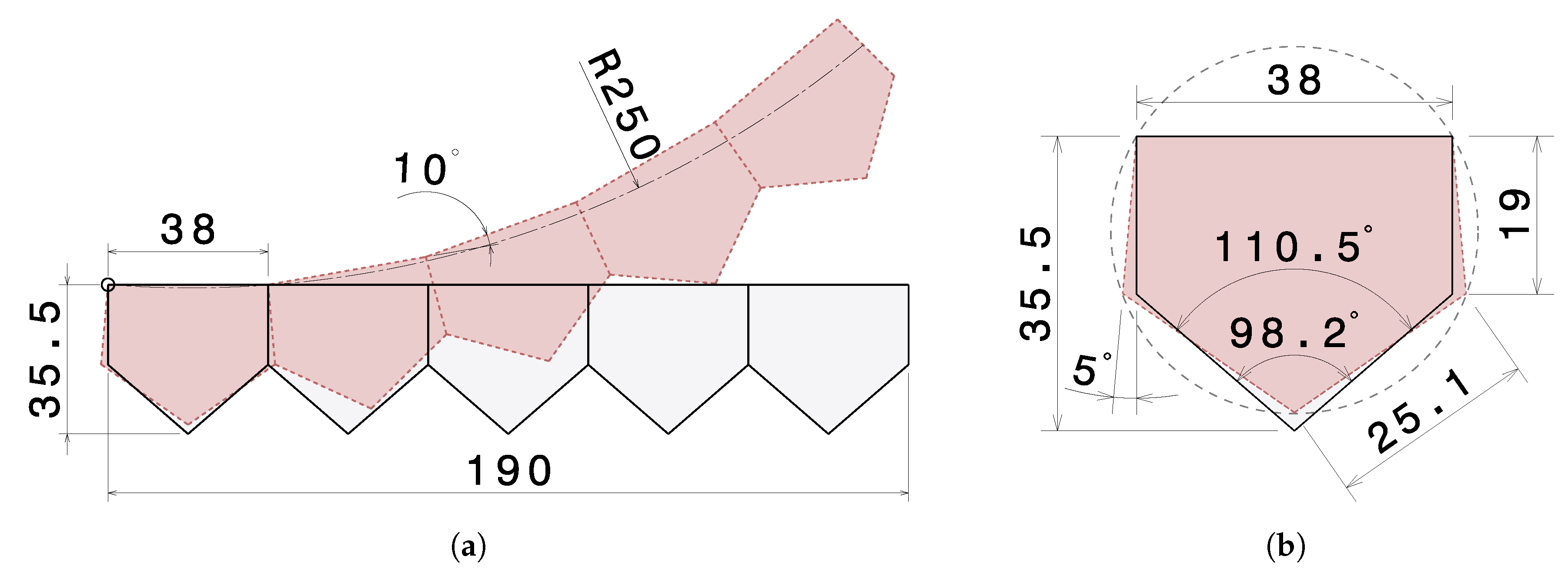
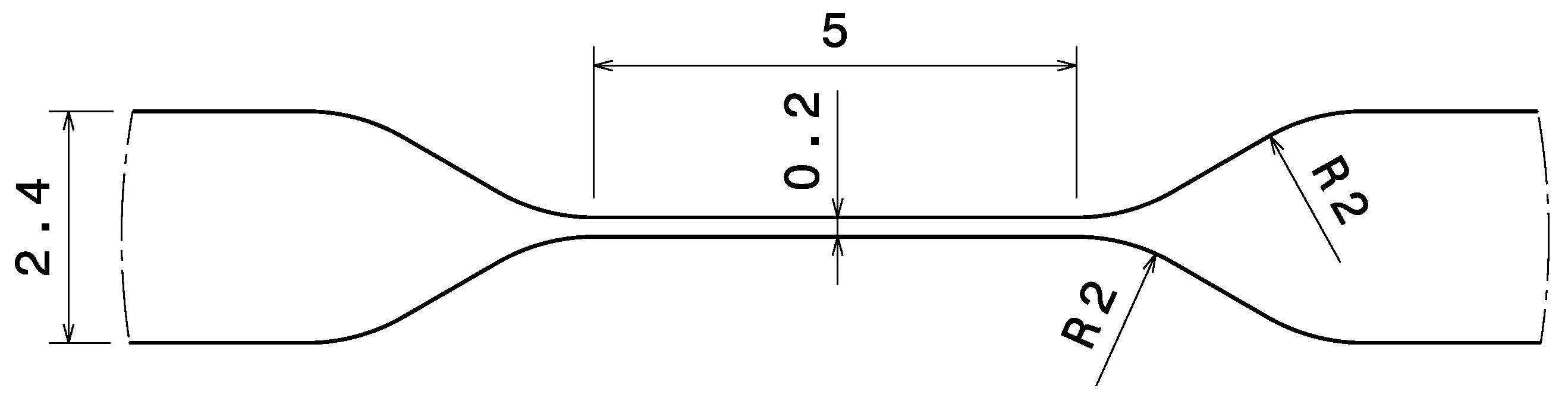
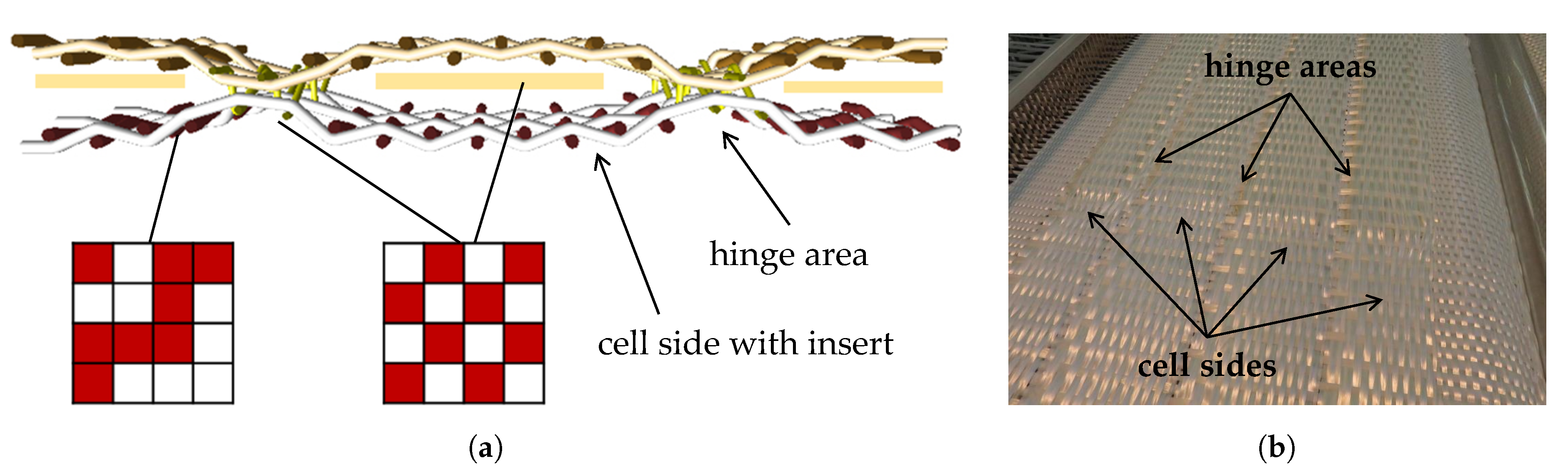
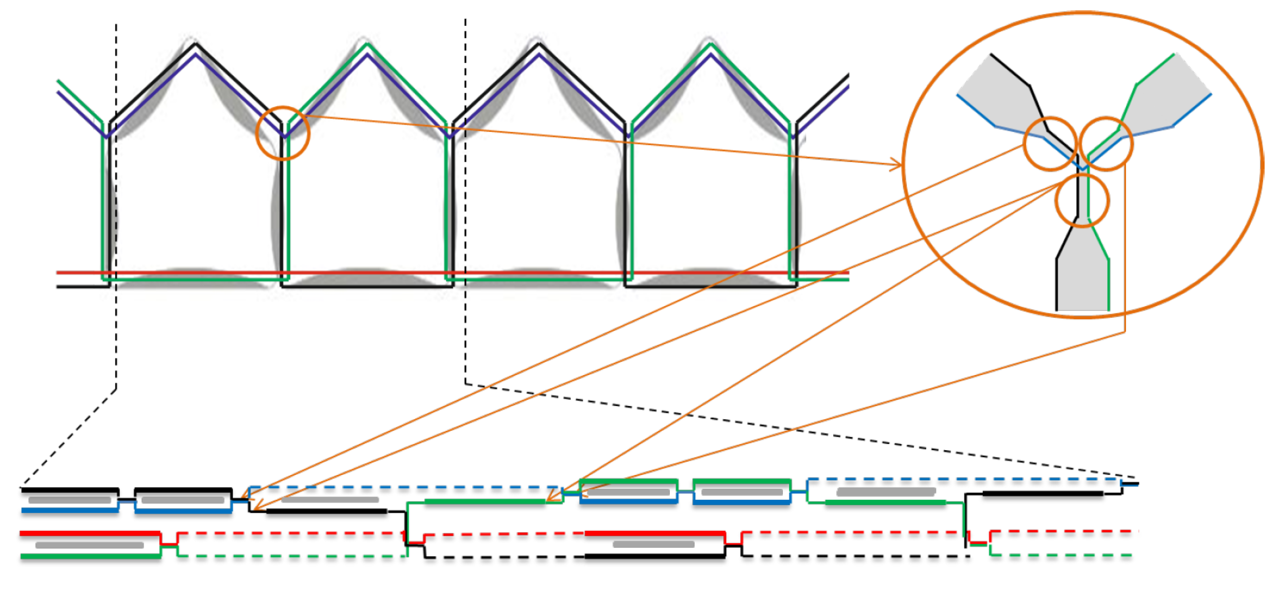
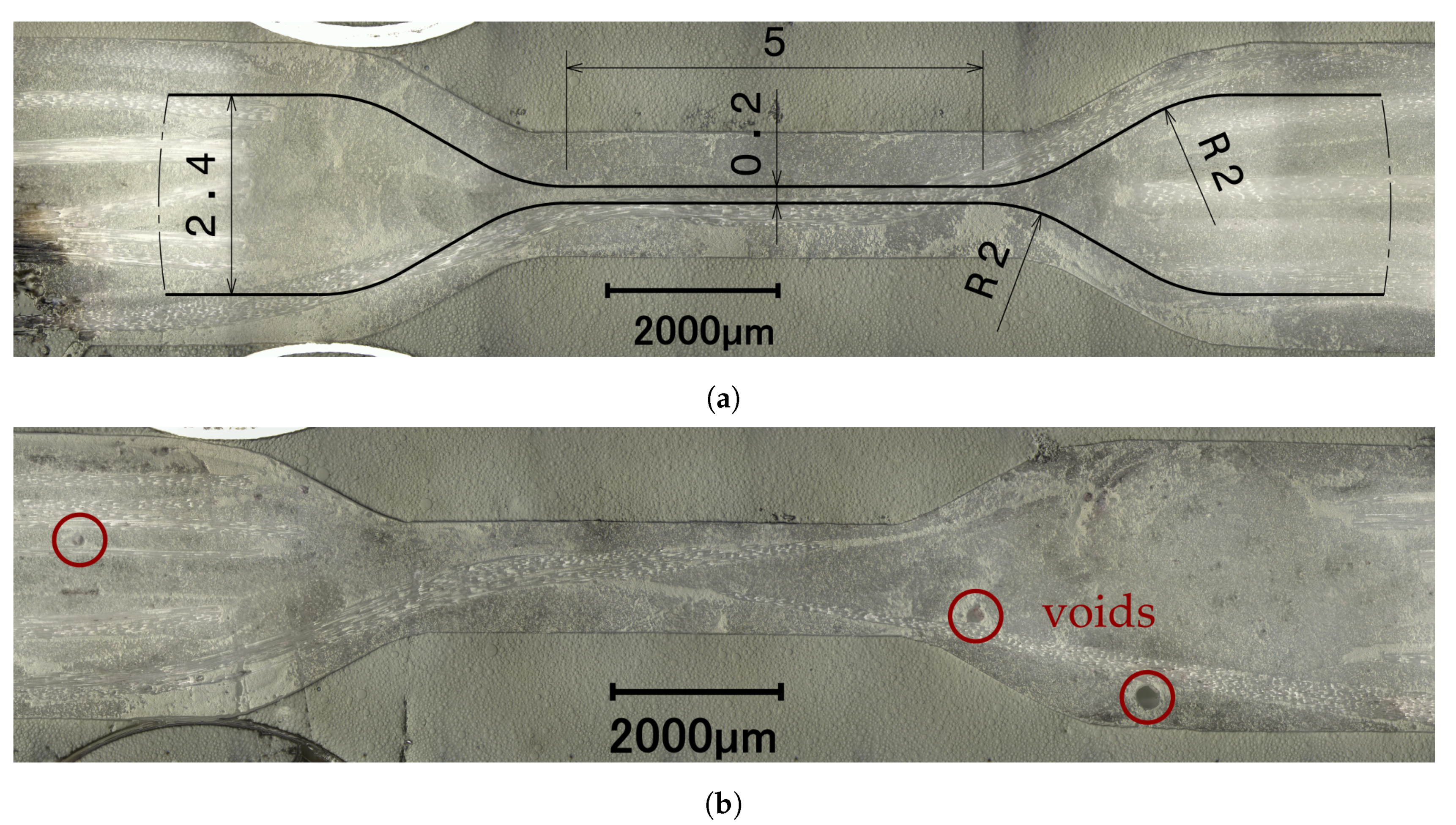
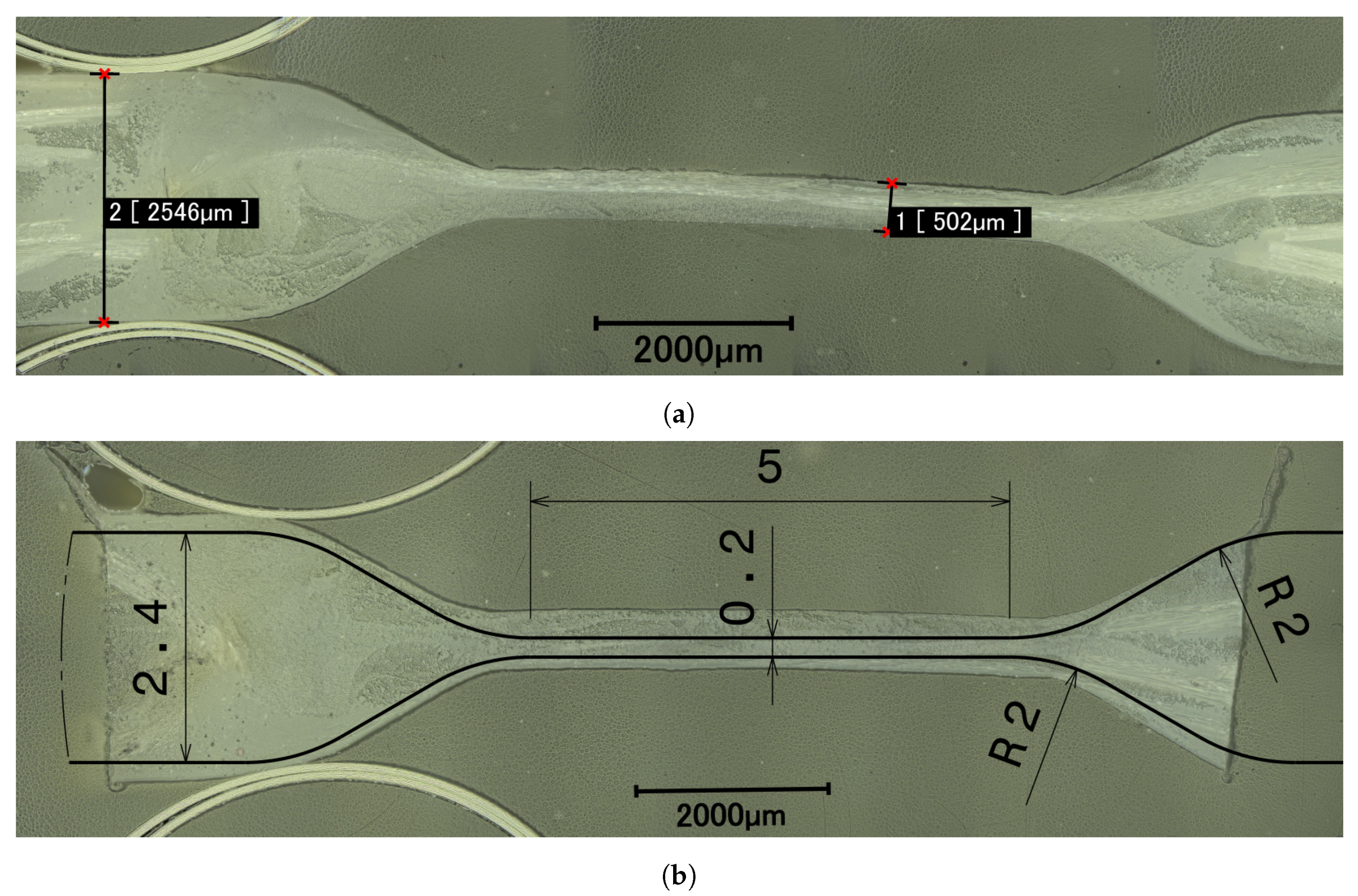
3.1. Flexure Hinge Design for PACS
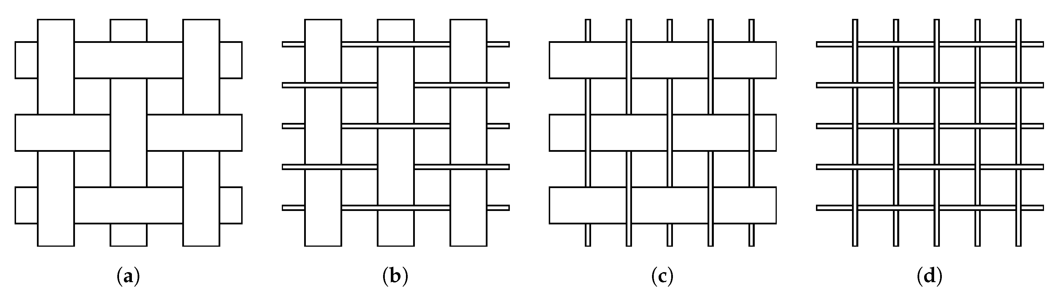
3.2. Material Selection for Weaving Process
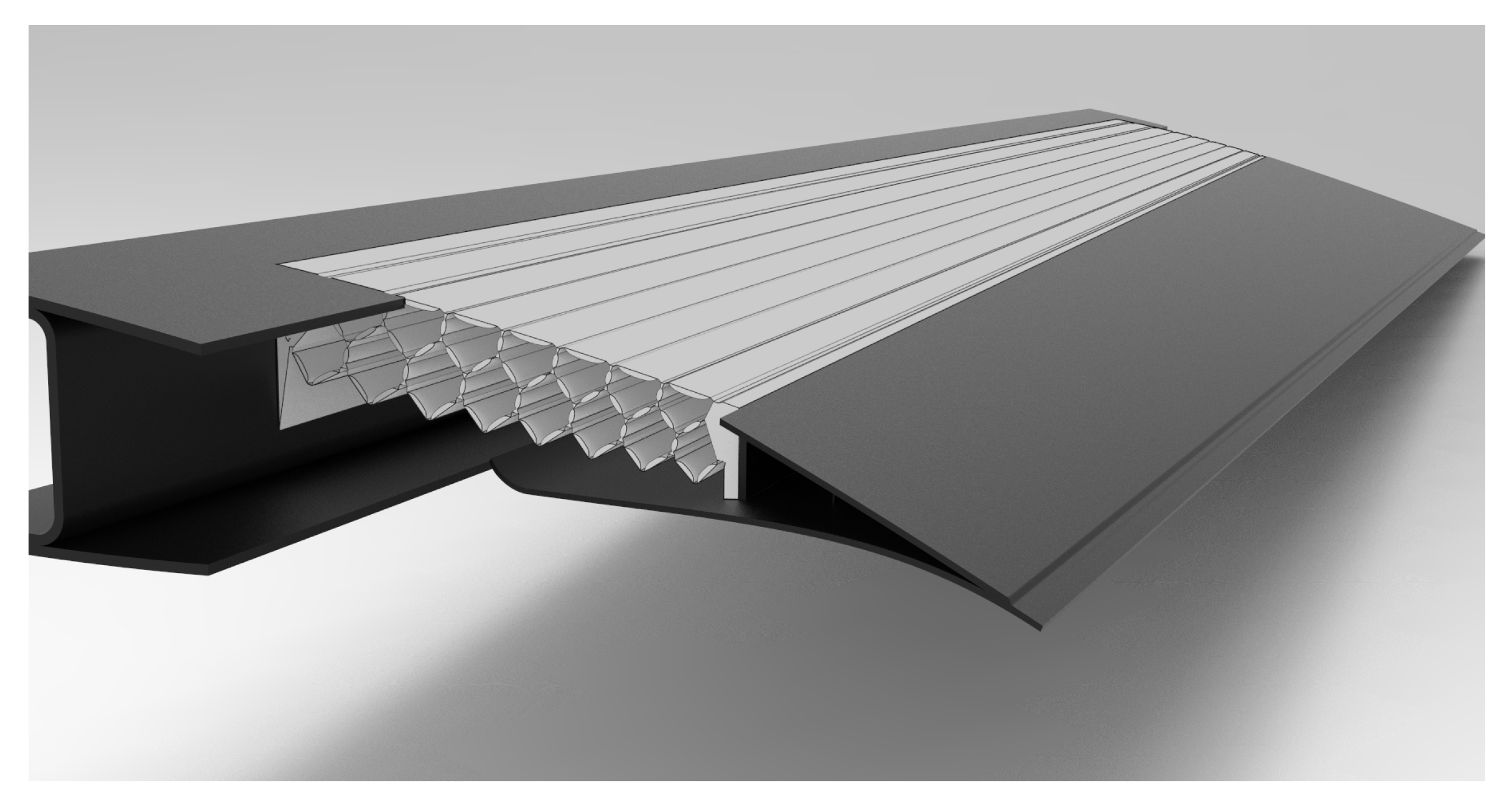
3.3. Manufacturing Process
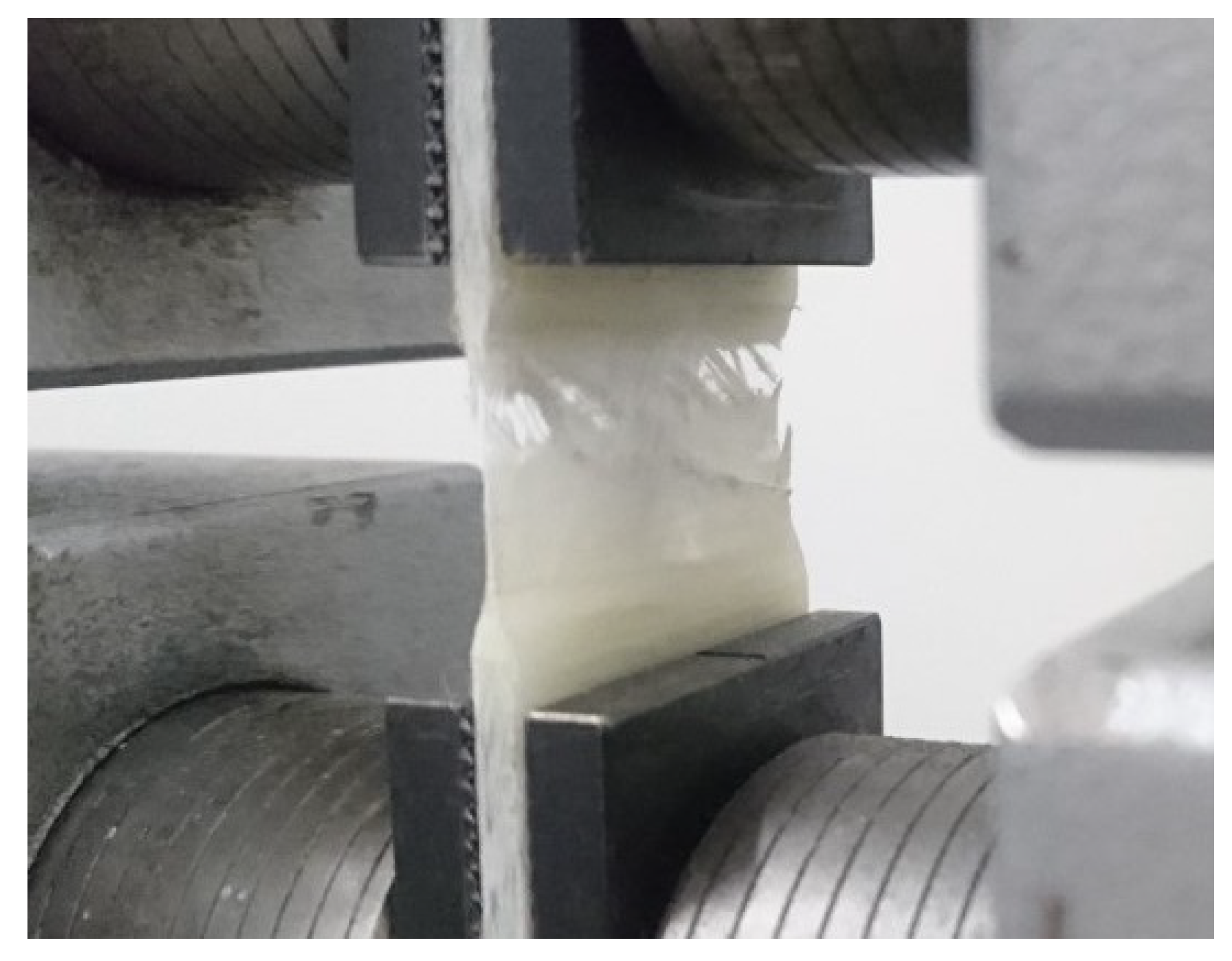
3.4. Mechanical Testing
4. Results
4.1. Prestests on Woven Plates
4.2. Woven FRP-Flexure Hinges
4.3. Woven FRP-PACS Cantilever
5. Discussion
Author Contributions
Funding
Acknowledgments
Conflicts of Interest
Abbreviations
| AVW | Approach of virtual work |
| CI | Confidence interval |
| FRP | Fiber reinforced plastic |
| FVC | Fiber volume content |
| GF | Glass-fiber |
| GFRP | Glass-fiber reinforced plastic |
| HCM | Hot compression molding |
| PA | Polyamide |
| PACS | Pressure-actuated cellular structure |
| SLS | Selective laser sintering |
References
- Sanders, B.; Eastep, F.E.; Forster, E. Aerodynamic and Aeroelastic Characteristics of Wings with Conformal Control Surfaces for Morphing Aircraft. J. Aircr. 2003, 40, 94–99. [Google Scholar] [CrossRef]
- Thill, C.; Etches, J.; Bond, I.; Potter, K.; Weaver, P. Morphing skins. Aeronaut. J. 2008, 112, 117–139. [Google Scholar] [CrossRef]
- Barbarino, S.; Bilgen, O.; Ajaj, R.M.; Friswell, M.I.; Inman, D.J. A Review of Morphing Aircraft. J. Intell. Mater. Syst. Struct. 2011, 22, 823–877. [Google Scholar] [CrossRef]
- Barrett, R.M. Active aeroelastic tailoring of an adaptive Flexspar stabilator. Smart Mater. Struct. 1996, 5, 723–730. [Google Scholar] [CrossRef]
- Elzey, D.M.; Sofla, A.; Wadley, H. A bio-inspired, high-authority actuator for shape morphing structures. Smart Mater. Struct. 2003, 5053, 92–100. [Google Scholar]
- Bauer, C.; Martin, W.; Siegling, H.F.; Schürmann, H. A new structural approach to variable camber wing technology of transport aircraft. In Proceedings of the 39th AIAA/ASME/ASCE/AHS/ASC Structures, Structural Dynamics, and Materials Conference and Exhibit, Long Beach, CA, USA, 20–23 April 1998; pp. 474–482. [Google Scholar] [CrossRef]
- Müller, D. Das Hornkonzept: Realisierung eines formvariablen Tragflügelprofils zur aerodynamischen Leistungsoptimierung zukünftiger Verkehrsflugzeuge. Ph.D. Thesis, Universität Stuttgart, Stuttgart, Germany, 2000. [Google Scholar]
- Li, S.; Wang, K.W. Plant-inspired adaptive structures and materials for morphing and actuation: A review. Bioinspir. Biomim. 2017, 12, 011001:1–011001:17. [Google Scholar] [CrossRef] [PubMed]
- Huber, J.E.; Fleck, N.A.; Ashby, M.F. The selection of mechanical actuators based on performance indices. Proc. R. Soc. Lond. Ser. A Math. Phys. Eng. Sci. 1997, 453, 2185–2205. [Google Scholar] [CrossRef]
- Barrett, R.M.; Barrett, C.M. Biomimetic FAA-certifiable, artificial muscle structures for commercial aircraft wings. Smart Mater. Struct. 2014, 23, 074011:1–074011:15. [Google Scholar] [CrossRef]
- Dittrich, K. Cellular Actuator Device and Methods of Making and Using Same. U.S. Patent US7055782B2, 6 June 2006. [Google Scholar]
- Vos, R.; Barrett, R.M. Pressure adaptive honeycomb: A novel concept for morphing aircraft structures. In Proceedings of the 27th Congress of the International Council of the Aeronautical Sciences, Nice, France, 19–24 September 2010; pp. 1792–1801. [Google Scholar]
- Vos, R.; Barrett, R.M. Method and Apparatus for Pressure Adaptive Morphing Structure. U.S. Patent US8366057B2, 5 February 2013. [Google Scholar]
- Vasista, S.; Tong, L. Topology-Optimized Design and Testing of a Pressure-Driven Morphing-Aerofoil Trailing-Edge Structure. AIAA J. 2013, 51, 1898–1907. [Google Scholar] [CrossRef]
- Luo, Q.; Tong, L. Adaptive pressure-controlled cellular structures for shape morphing I: Design and analysis. Smart Mater. Struct. 2013, 22, 055014:1–055014:16. [Google Scholar] [CrossRef]
- Luo, Q.; Tong, L. Adaptive pressure-controlled cellular structures for shape morphing II: Numerical and experimental validation. Smart Mater. Struct. 2013, 22, 055015:1–055015:12. [Google Scholar] [CrossRef]
- Lv, J.; Tang, L.; Li, W.; Liu, L.; Zhang, H. Topology optimization of adaptive fluid-actuated cellular structures with arbitrary polygonal motor cells. Smart Mater. Struct. 2016, 25, 055021:1–055021:13. [Google Scholar] [CrossRef]
- van Meerbeek, I.M.; Mac Murray, B.C.; Kim, J.W.; Robinson, S.S.; Zou, P.X.; Silberstein, M.N.; Shepherd, R.F. Morphing Metal and Elastomer Bicontinuous Foams for Reversible Stiffness, Shape Memory, and Self-Healing Soft Machines. Adv. Mater. 2016, 28, 2801–2806. [Google Scholar] [CrossRef] [PubMed]
- Boyraz, P.; Runge, G.; Raatz, A. An Overview of Novel Actuators for Soft Robotics. Actuators 2018, 7, 48. [Google Scholar] [CrossRef]
- Pagitz, M.; Lamacchia, E.; Hol, J. Pressure-actuated cellular structures. Bioinspir. Biomim. 2012, 7, 016007:1–016007:19. [Google Scholar] [CrossRef] [PubMed]
- Gramüller, B.; Boblenz, J.; Hühne, C. PACS—Realization of an adaptive concept using pressure actuated cellular structures. Smart Mater. Struct. 2014, 23, 115006:1–115006:17. [Google Scholar] [CrossRef]
- Gramüller, B.; Köke, H.; Hühne, C. Holistic design and implementation of pressure actuated cellular structures. Smart Mater. Struct. 2015, 24, 125027:1–125027:28. [Google Scholar] [CrossRef]
- Sinapius, M. Adaptronik: Prinzipe-Funktionswerkstoffe-Funktionselemente-Zielfelder mit Forschungsbeispielen; Springer: Berlin, Germany, 2018. [Google Scholar] [CrossRef]
- Gramüller, B.; Tempel, A.; Hühne, C. Shape-variable seals for pressure actuated cellular structures. Smart Mater. Struct. 2015, 24, 095005:1–095005:20. [Google Scholar] [CrossRef]
- Gramüller, B. On Pressure-Actuated Cellular Structures. Ph.D. Thesis, Technische Universität Braunschweig, Braunschweig, Germany, 2016. [Google Scholar]
- Sennewald, C.; Vorhof, M.; Schegner, P.; Hoffmann, G.; Cherif, C.; Boblenz, J.; Sinapius, M.; Hühne, C. Development of 3D woven cellular structures for adaptive composites based on thermoplastic hybrid yarns. IOP Conf. Ser. Mater. Sci. Eng. 2018, 369, 012041:1–012041:7. [Google Scholar] [CrossRef]
- Sennewald, C.; Vorhof, M.; Hoffmann, G.; Cherif, C. Overview of Necessary Development Steps for the Realization of Woven Cellular Structures for Adaptive Composites. J. Fash. Technol. Text. Eng. 2018, s5, 001:1–001:6. [Google Scholar] [CrossRef]
- Tsai, S.W.; Hahn, H.T. Introduction to Composite Materials; Technomic Publishing Company: Lancaster, PA, USA, 1980. [Google Scholar]


| Parameter | Values |
|---|---|
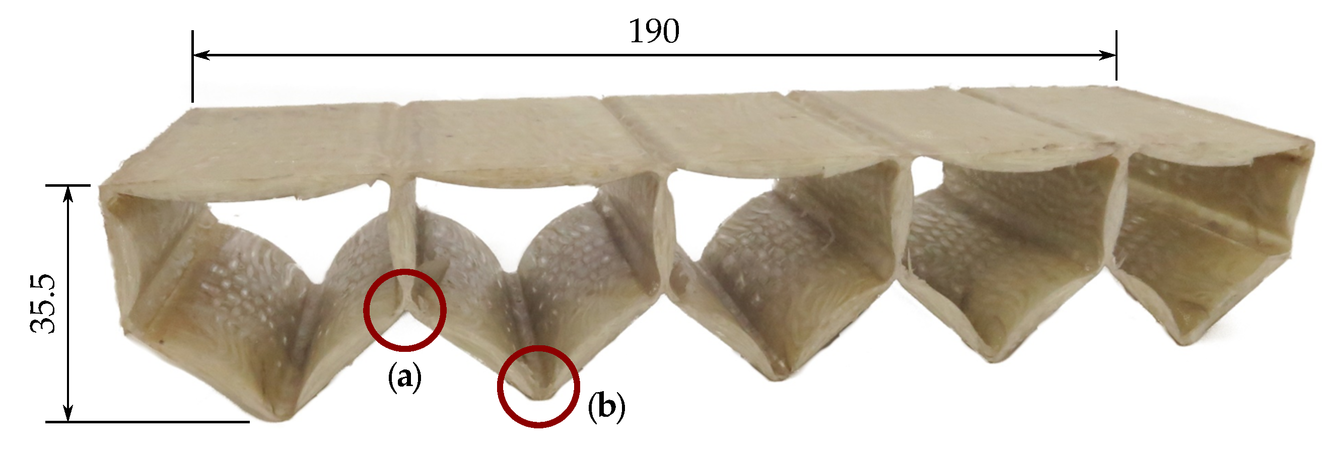
| Dimensions (cantilever) | 190 × 35.5 × 200 mm3 |
| Dimensions (single cell) | 038 × 35.5 × 200 mm3 |
| Maximum design pressure | 0.75 MPa |
| Angular displacement per cell | 10° |
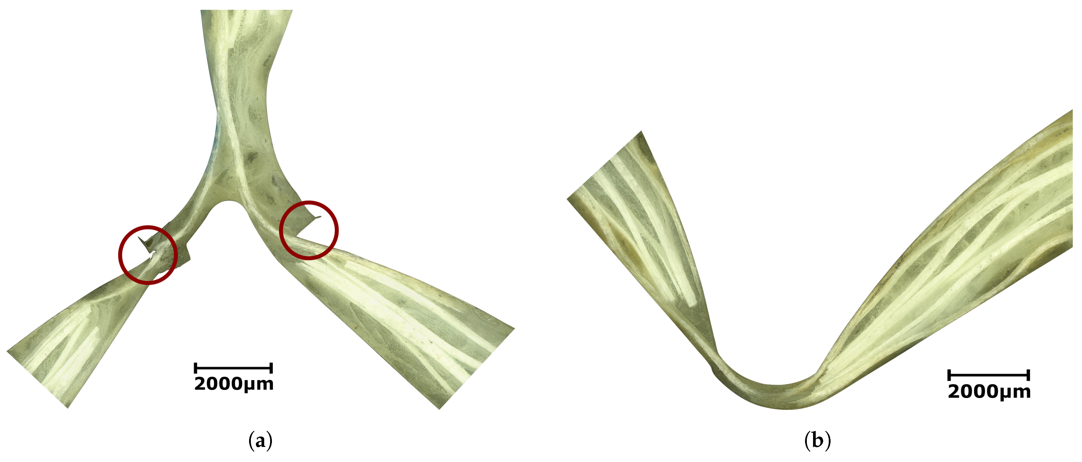
| Hinge length l | 0.5 mm |
| Hinge thickness t | 0.2 mm |
| Cell side thickness | 2.4 mm |
| Yarn | Fineness | Compound | Shape and Dimensions | FVC GF |
|---|---|---|---|---|
| Twisted yarn | 0900 tex | 2 × GF tex 300 + 1 × PA6 300 tex | 20 turns per meter (⌀~0.7 mm) | 46% |
| TecTape | 1800 tex | 1 × GF 1200 tex + 2 × PA6 300 tex | tape-like shape (8 mm × 0.2 mm) | 46% |
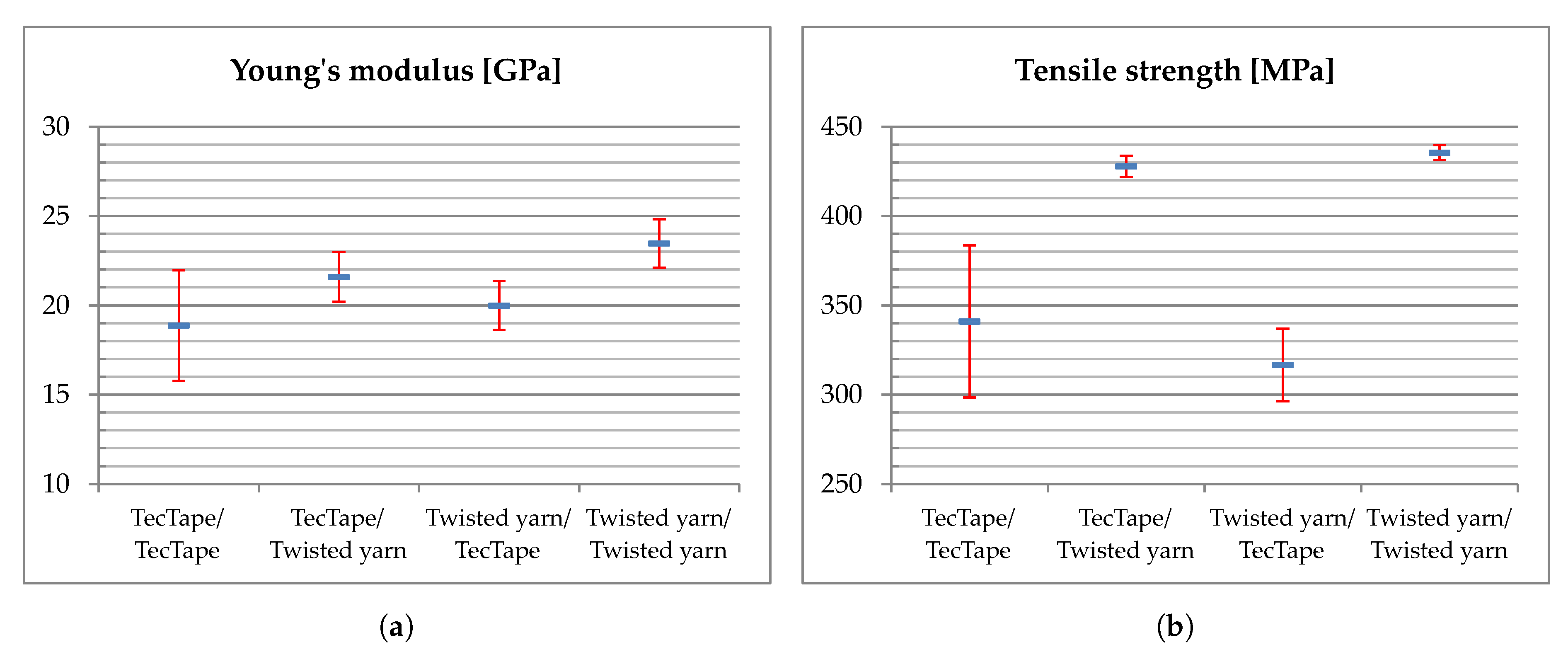
| Fabric (warp/weft) | Young‘s Modulus [GPa] | Tensile Strength [MPa] | Elongation at Break [%] | Ratio R2/E [MPa] |
|---|---|---|---|---|
| TecTape/TecTape | 18.86 ± 3.08 | 340.87 ± 42.63 | 2.22 ± 0.18 | 6.16 |
| TecTape/Twisted yarn | 21.58 ± 1.38 | 427.64 ± 05.89 | 2.50 ± 0.08 | 8.47 |
| Twisted yarn/TecTape | 19.98 ± 1.37 | 316.55 ± 20.36 | 1.97 ± 0.13 | 5.02 |
| Twisted yarn/Twisted yarn | 23.46 ± 1.36 | 435.38 ± 04.14 | 2.48 ± 0.08 | 8.08 |
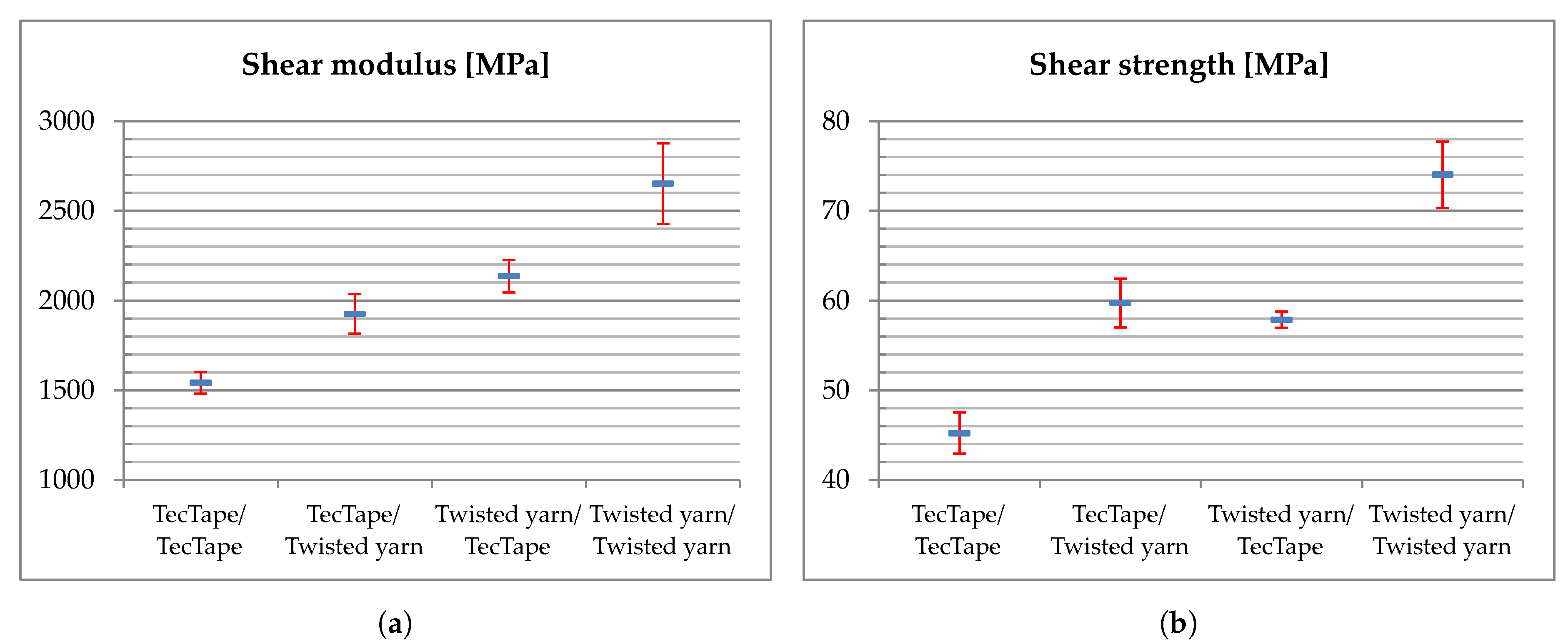
| Fabric (warp/weft) | Shear Modulus [MPa] | Shear Strength [MPa] |
|---|---|---|
| TecTape/TecTape | 1541.53 ± 061.00 | 45.21 ± 2.29 |
| TecTape/Twisted yarn | 1925.13 ± 110.09 | 59.72 ± 2.72 |
| Twisted yarn/TecTape | 2136.24 ± 091.52 | 57.84 ± 0.92 |
| Twisted yarn/Twisted yarn | 2651.73 ± 225.42 | 74.02 ± 3.72 |
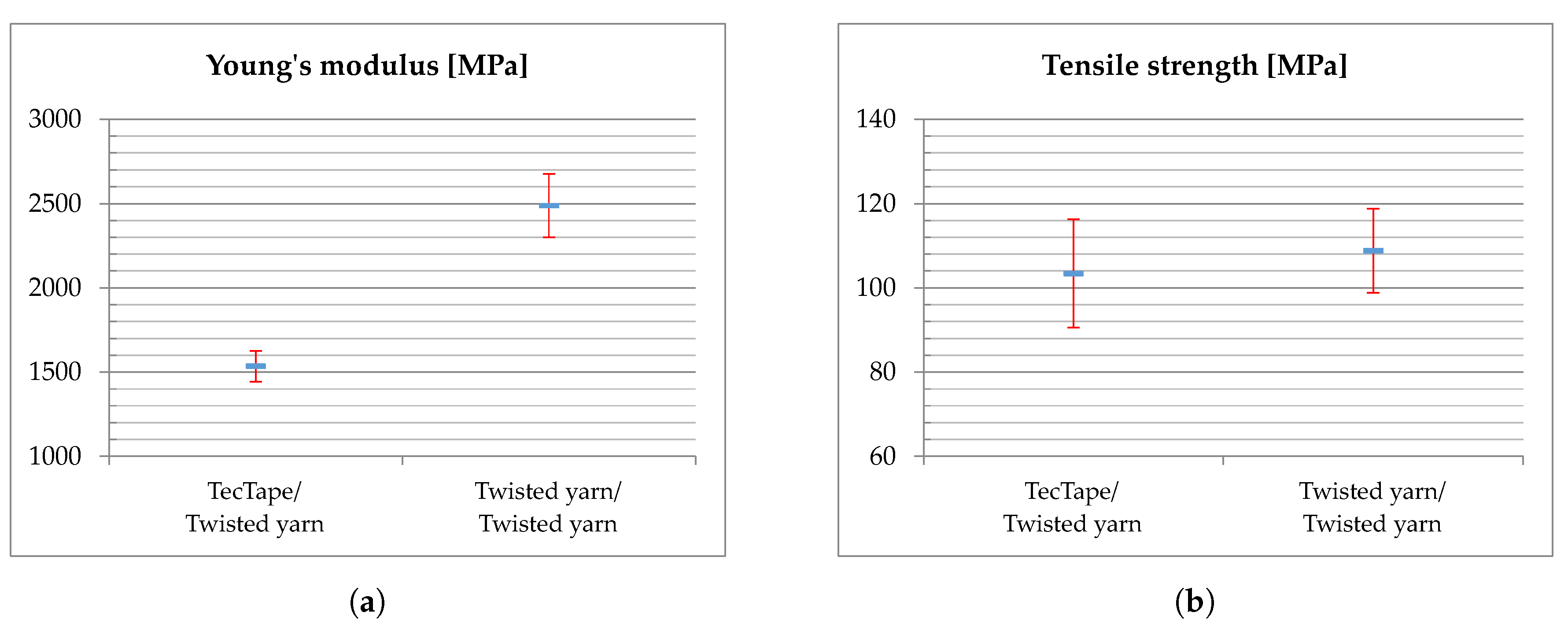
| Fabric (warp/weft) | Young‘s Modulus [MPa] | Tensile Strength [MPa] | Ratio [MPa] |
|---|---|---|---|
| TecTape/Twisted yarn | 1534.79 ± 092.41 | 103.43 ± 12.87 | 6.97 |
| Twisted yarn/Twisted yarn | 2487.71 ± 187.37 | 108.82 ± 09.98 | 4.76 |
© 2019 by the authors. Licensee MDPI, Basel, Switzerland. This article is an open access article distributed under the terms and conditions of the Creative Commons Attribution (CC BY) license (http://creativecommons.org/licenses/by/4.0/).
Share and Cite
Meyer, P.; Boblenz, J.; Sennewald, C.; Vorhof, M.; Hühne, C.; Cherif, C.; Sinapius, M. Development and Testing of Woven FRP Flexure Hinges for Pressure-Actuated Cellular Structures with Regard to Morphing Wing Applications. Aerospace 2019, 6, 116. https://doi.org/10.3390/aerospace6110116
Meyer P, Boblenz J, Sennewald C, Vorhof M, Hühne C, Cherif C, Sinapius M. Development and Testing of Woven FRP Flexure Hinges for Pressure-Actuated Cellular Structures with Regard to Morphing Wing Applications. Aerospace. 2019; 6(11):116. https://doi.org/10.3390/aerospace6110116
Chicago/Turabian StyleMeyer, Patrick, Johannes Boblenz, Cornelia Sennewald, Michael Vorhof, Christian Hühne, Chokri Cherif, and Michael Sinapius. 2019. "Development and Testing of Woven FRP Flexure Hinges for Pressure-Actuated Cellular Structures with Regard to Morphing Wing Applications" Aerospace 6, no. 11: 116. https://doi.org/10.3390/aerospace6110116