1. Introduction
Carbon fiber reinforced polymer composites have been widely adopted from the aeronautical industry (e.g., 52% in Airbus A350, 50% in Boeing B787 etc.) in primary as well as secondary structures, as well as in many other similar lightweight structures, which leads to decreased fuel consumption. On the other hand, it is worth mentioning that the selection process of the appropriate material for an aircraft structural application is a vital step, made at the early design stages, and has to fulfill a number of currently applied structural optimization criteria (weight reduction, cost minimization, efficient mechanical properties, etc.). In parallel, environmental considerations should, nowadays, represent a significant parameter both for selecting a material, as well as for designing an aircraft’s structure and manufacturing it.
The mainstream composite material type for aeronautical applications is thermosetting composites, mainly carbon fiber reinforced epoxies, because of their low processing temperatures, low viscosity, superior adhesion to fibers, fatigue strength, etc. However, issues associated with their long curing cycles which lead to low production rates combined with growing environmental concerns associated with their end-of-life treatment, as well as the adoption of stricter environmental policies, have turned the attention of the aeronautical industry to alternative solutions.
On the other hand, thermoplastic composites have the ability to melt under heat and harden after cooling creating a new shape. This process can be repeated multiple times. This characteristic offers possibilities for adopting faster composite processing techniques with reduced processing time. Moreover, thermoplastic composites exhibit superior impact and chemical resistance, unlimited shelf-life, and the ability to assemble sub-structures by welding, which leads to weight reduction and recyclability; properties that thermosetting composites are unable to provide. On the downside, the higher processing temperatures and pressures needed for processing these materials, which leads to both increased energy consumption and tooling cost, are key barriers for their wide-scale use for the construction of primary structures by the aeronautical industry. Additionally, the severe deterioration of the mechanical properties of the materials during the recycling process poses a burden for exploiting their recyclability.
As far as the manufacturing techniques are concerned, out of autoclave techniques demonstrate high potential for significant financial and environmental benefits as compared to the conventional autoclave process, although autoclaving is expected to lead to higher product quality. However, concerning the recycling processes, the recyclability of the material is still defined on the basis of commonly used recycling methods, including pyrolysis and landfill, which might exhibit lower energy demands. However, they lead to products with a low or without reusability potential. These conflicting parameters underline the necessity for developing tools and concepts allowing the simultaneous optimization of a product with regard to quality, cost and environmental impact.
The available works on this topic are few and limited to either the environmental footprint or the cost quantification of a product. In this context, several studies have performed either Life Cycle Analysis (LCA) of carbon fiber reinforced polymers, e.g., [
1,
2,
3,
4,
5,
6,
7] or Life Cycle Costing (LCC) analysis, e.g., References [
8,
9,
10,
11] of carbon fiber reinforced polymers. An LCA study was conducted by Timmis et al. [
1] to quantify the environmental impact derived from the use of composite materials in an aircraft’s fuselage used in place of other structural materials (e.g., aluminum alloys). The results highlighted that the overall environmental impact which occurred from the adoption of composite materials is positive compared with traditional materials (e.g., aluminum). In Reference [
2] an overview of currently used composite materials for aviation, as well as possible bio-based and recycled substitution materials, with the focus on their ecological properties is presented. Apart from conventional materials, several types of novel materials were considered to reduce ecological impacts compared to the state-of-the-art, such as bio-based thermoset resins (epoxy, furan), bio-based fibers (flax, ramie) and recycled carbon fibers. Moreover, Duflou et al. [
3] and Song et al. [
4] quantified the environmental footprint of composites when they replaced steel, which is of limited use in aircraft structural applications (e.g., 7% in A350), but of great importance in automotive applications. Both latter studies demonstrated that composite materials outperformed steel due to the weight savings that they offer during the in-use phase.
Furthermore, a number of studies are dedicated to the cost efficiency assessment of the composite materials, e.g., References [
8,
9,
10,
11]. In Reference [
8], an overview of the extensive field of cost estimation for aerospace composite production, describing the basic methods of how to perform cost estimation and introducing some of the existing LCC models, is made. In addition, in Reference [
10], an LCC procedure is developed using cost equations to accurately estimate the recurring cost to manufacture of an aircraft control surface (leading edge flap) applicable to resin transfer molding (RTM) and vacuum-assisted resin transfer molding (VARTM). A novel concept for the optimization of manufacturing processes of composite material components with regard to product’s quality and cost is introduced in Reference [
11] and applied for the case of thermoplastic composite helicopter canopies produced by ‘cold’ diaphragm forming (CDF) process.
On the other hand, a limited number of existing works refer to combined LCA and LCC analyses [
12,
13,
14,
15,
16,
17,
18,
19,
20]; the few available works are rarely related to composites. In Reference [
13] the application of an LCA/LCC integrated model is described for the comparison of an AGL (Anti-Glare Lamellae) currently manufactured from virgin HDPE (High Density PolyEthylene) with an alternative one made with recycled HDPE. The obtained results show that neither the current nor the new AGL depict the best environmental performance in all impact categories. Nevertheless, a clear overall environmental and economic advantage in replacing virgin HDPE with recycled HDPE was exhibited. Reference [
14] combines LCC and LCA in the case of a residential district energy system area in Finland aiming to identify the actual technologies that could provide the highest sustainable viability and assesses the emissions and relative mitigation potentials associated with the different technologies. Furthermore, in Reference [
17] an LCA study, as well as an LCC analysis, were carried out for a refractory brick production company, and in Reference [
18] the evaluation of the process-based cost and environmental footprint profile of green composite under a twofold assessment is considered.
In Reference [
20] a combined environmental and cost assessment dedicated to composite materials is performed. However, it is on an automotive application (steel vehicle bulkhead). In this study, the economic and environmental effects of substituting steel for lighter weight alternatives with the focus on composite materials was presented; thus, four material scenarios, as well as automated preforming technology, combined with reaction injection molding were chosen. Manufacturing and life-cycle costs were derived from a technical cost model, and the environmental performance of each scenario was then quantified using LCA according to ISO guidelines. Therefore, there is not any available work in the open literature, combining the comparison of a number of processes used in aeronautics with regards both to LCA and LCC studies for a composite aeronautic product, either thermoplastic or thermoset.
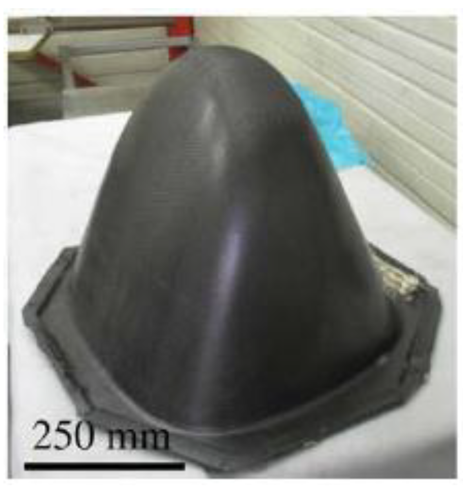
This work aims to make a comparative analysis in terms of carbon emissions and financial efficiency for different material, manufacturing, and recycling scenarios associated with the production of an aeronautical structural component; the canopy of the EUROCOPTER EC Twin Star helicopter described in Reference [
11],
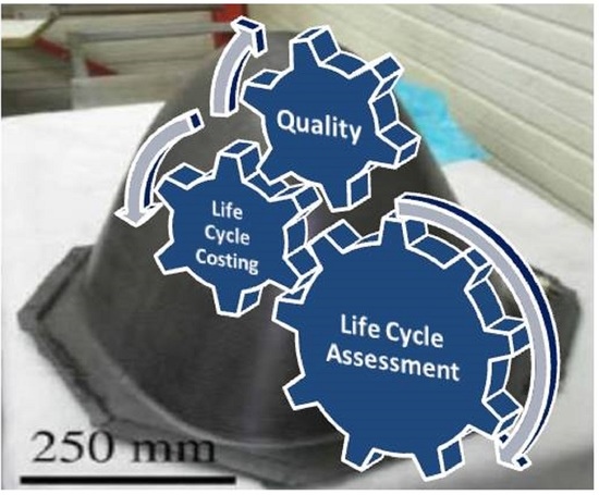
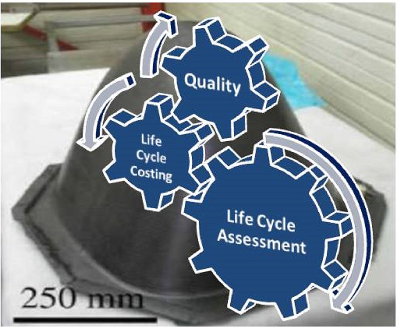
Figure 1. In addition, the present work introduces a new holistic approach which accounts for not only cost and environmental footprint but also for additional features, such as the quality of the product as well as reusability and recyclability aspects. In such an approach, these features would be taken into account at the design phase of a product.
2. Methods
2.1. Life Cycle Analysis
Life cycle analysis is a standardized technique (ISO 14040 2006 [
21]) for assessing the environmental performance of a product or a process at various points in their life cycle, from raw material extraction to disposal or recycling. The stages for carrying out a Life Cycle Analysis are the following: Goal and scope definition, inventory analysis, impact assessment, and interpretation of the results.
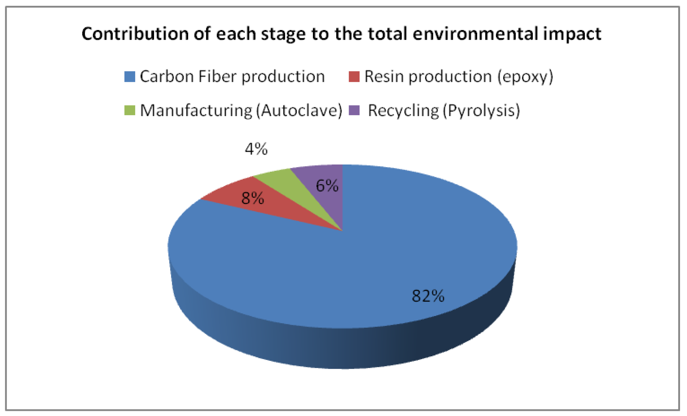
Based on this concept, an LCA model was developed for evaluating the environmental footprint in terms of carbon emissions of the canopy of the Twin Star Helicopter, which is the case study under investigation, acting as the functional unit of the system. The stages taken into consideration for the present LCA were: carbon fiber production, epoxy (TS) and PEEK (PolyEtherEtherKetone)-(TP) production, manufacturing (autoclave, resin transfer molding (RTM), cold diaphragm forming (CDF)) and recycling (mechanical recycling and pyrolysis).
Epoxy resins are the most commonly used matrix material for composite material aircraft structural applications. In this context, toughened epoxies have found widespread application. However, their use in high-performance applications is limited by low service temperature that is adversely affected by moisture content, loading, and by the use of toughening agents. In general, the maximum use temperature for advanced epoxies is limited to 150 °C to 180 °C. Other disadvantages include brittleness and moisture absorption that can lower use temperature as mentioned above. However, epoxy resins provide many attractive features, including good handling properties, processability, and low cost.
On the other hand, PEEK (PolyEtherEtherKetone) is commonly used for the matrix of TP prepregs containing mainly carbon fibers and is selected as the most prevalent TP resin used in aeronautics. PEEK has been reported to be capable of withstanding continuous operating temperature up to 260 °C in low-stress operations and 120 °C in aerospace structural applications. Moreover, PEEK has good resistance to hydrolysis, corrosion, chemical, and radiation exposure. It provides high thermal stability, a low coefficient of expansion, good abrasion resistance, low smoke and toxic gas emission, and excellent stiffness. Last, but not least, an essential advantage is recyclability which, however, requires high energy consumption.
In the present work, a Bisphenol-A epoxy-based vinyl ester resin was selected as the TS representative of toughened epoxies and PolyEtherEtherKetone (PEEK) resin as a TP competitor, both reinforced with carbon fibers. These systems were chosen to compare the environmental impact and cost of a commonly used non-recyclable material (epoxy composite) with a recyclable material (PEEK composite).
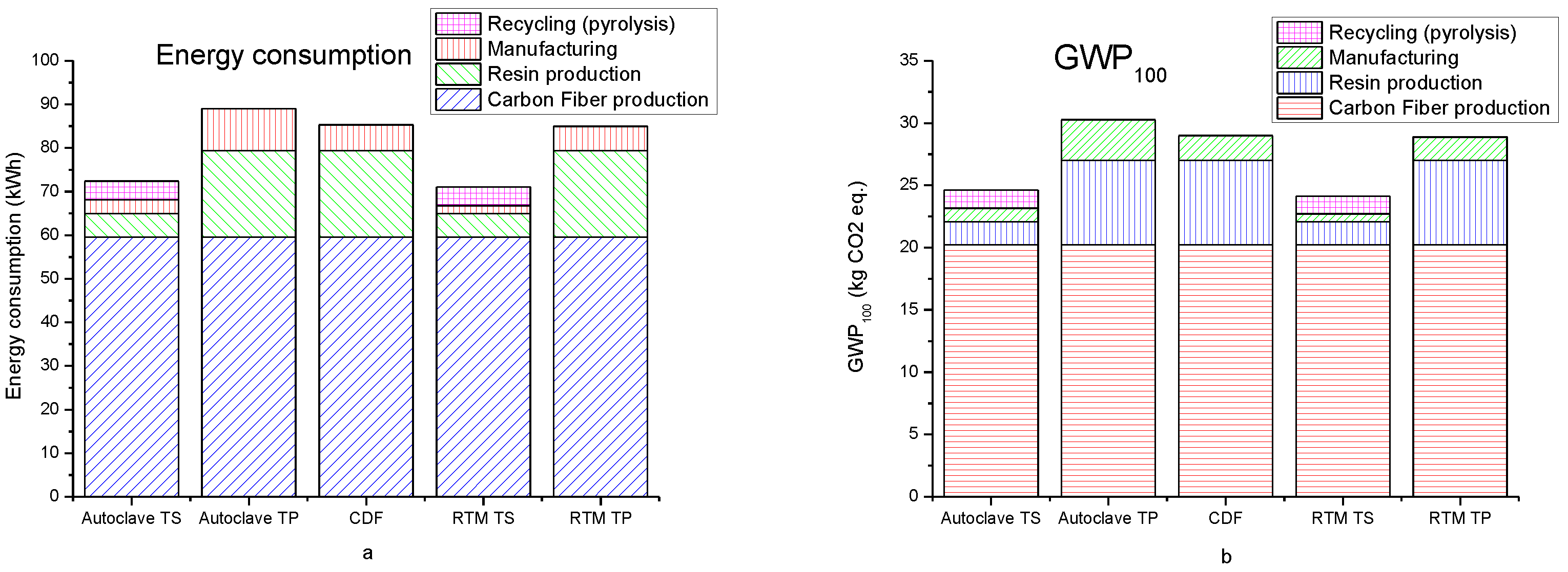
In regard to the processes under investigation, autoclave and RTM, as a representative of autoclave processes, were selected as they are the most commonly used processes to produce structural aeronautical components. They are capable of producing parts of acceptable quality according to the aeronautics standards. Cold diaphragm forming (CDF), has a low cost and seems to be promising for aeronautical applications. Therefore, the above mentioned three processes were selected for our investigation. CDF was considered only for the thermoplastic composite, as it cannot be used to process thermosetting matrices, whereas autoclave and RTM can be used for both. Moreover, pyrolysis was considered only for the scenarios involving thermosetting composite as the material of choice whereas mechanical recycling was considered for both thermoplastic and thermosetting composites. The processes under investigation were assumed to be all electric.
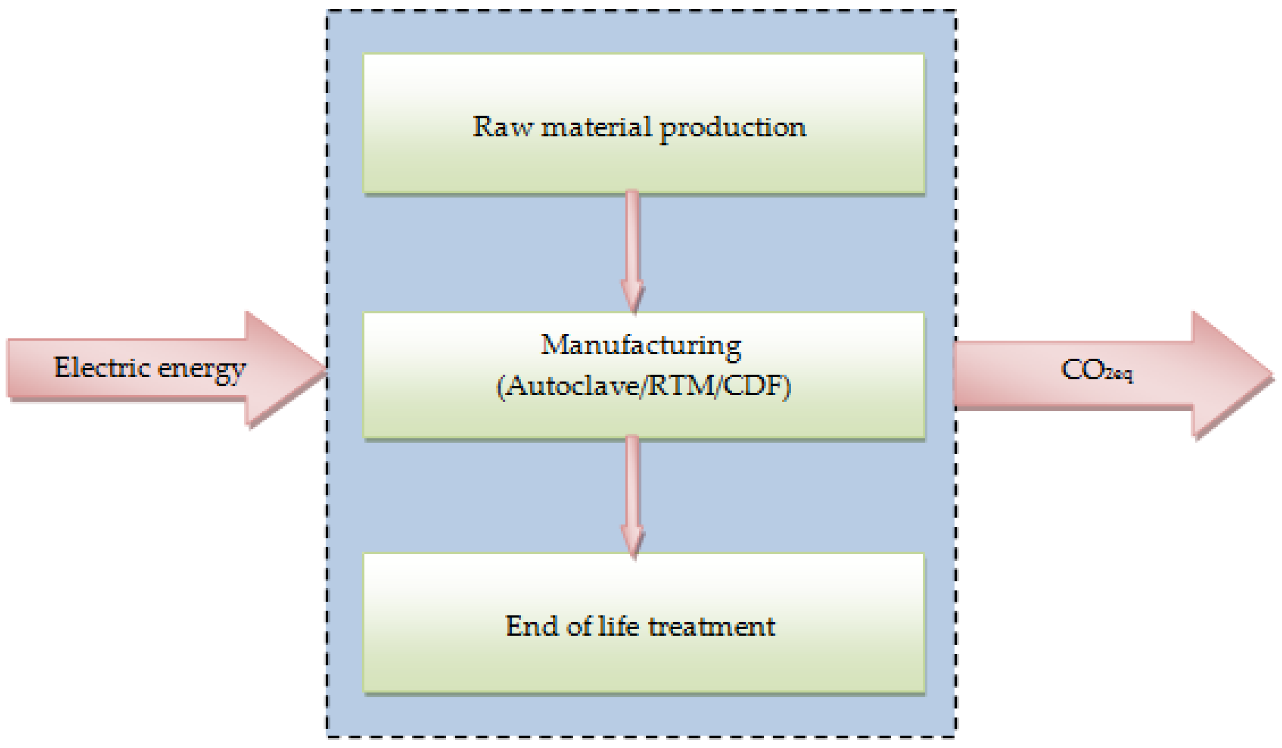
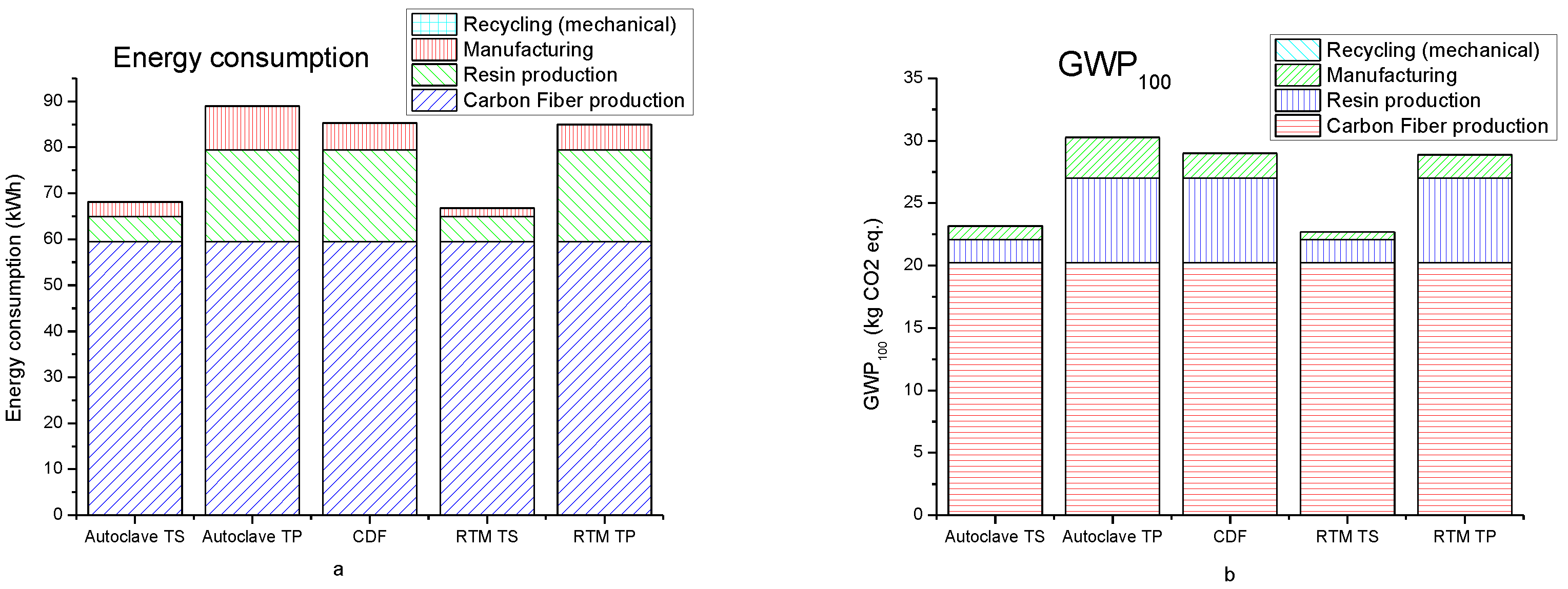
For each stage, the total energy demands, as well as the Global Warming Potential-100 (GWP
100) for a period of 100 years, were estimated. GWP
100 was selected as the most critical environmental impact category commonly used among LCA studies for evaluating the carbon footprint and is suitable for this study as electricity generation produces mainly CO
2 emissions. The system boundaries are shown in
Figure 2. The total energy consumption was calculated by multiplying the mass of each material with the energy intensity of each process (Equation (1)), which was derived from literature [
5,
22,
23,
24,
25] and is shown in
Table 1. Since the processing temperature of PEEK is almost three times higher than the processing temperature of epoxy, the energy demands at the manufacturing stage were assumed to be three times higher as well. The GWP
100 was calculated by multiplying the
mCO2eq, which is the mass of CO
2 emission that is produced from the consumption of 1 kWh of electricity, with the total energy demands of each process (Equation (2)). The
mCO2eq was considered equal to 0.34 kg CO
2eq/kWh [
26].
where
Ei is the total energy of each process in kWh,
mi is the total mass in kg of each material involved,
ei is the energy intensity for each process in kWh/kg, GWP
100 is the Global Warming Potential for a period of 100 years in kg,
mCO2eq is the mass in kg of CO
2 emission that is produced from the consumption of 1 kWh of electricity.
2.2. Life Cycle Costing
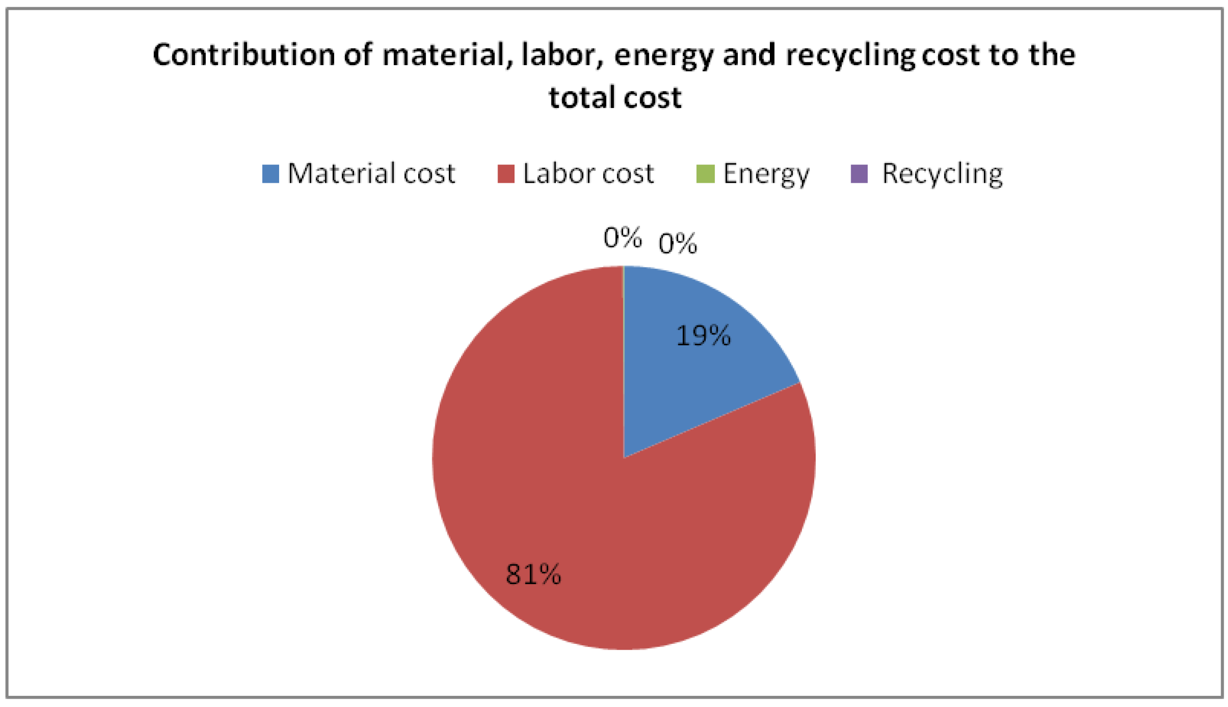
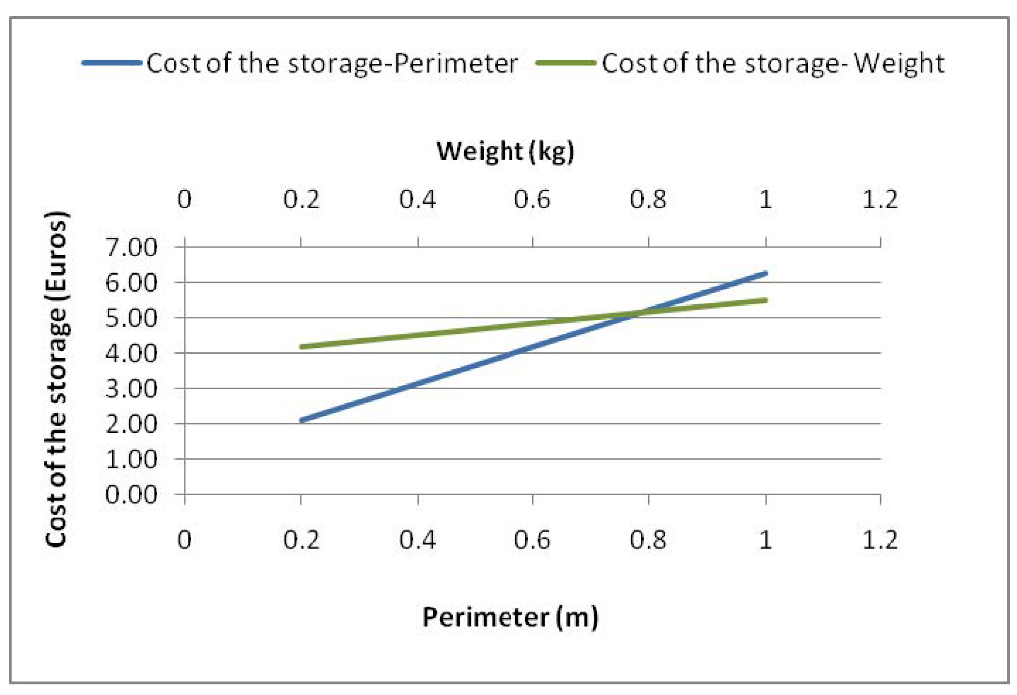
The Life Cycle Cost analysis is a suitable tool for determining financial trade-offs arising from a product or a process. In this study, an LCC model was developed based on the principles of the Activity Based Costing method (ABC). ABC is an accounting method implementing cost estimation mathematical relationships (CERs) for expressing the cost as a function of one or more independent variables that take into account the geometrical features of a material or a product, such as the perimeter (PAP), surface (PAA), length (L) shape complexity (cmp), and mass (WP). In the performed analysis, costs associated with labor, material, and energy were calculated. The performed cost analysis also accounts for recycling cost which was assumed equal to the energy cost of the recycling process. CERs were either formulated or adopted from Reference [
11].
In the framework of the LCC analysis, the cost of 1 kWh was considered equal to 0.114 Euros [
27] and the labor cost (
kw) equal to 32.6 Euros/hour [
27]. The cost of the raw material was considered equal to the cost of its constituents (
Kmf is the cost of carbon fibers and
Kmr the cost of the resin). Additionally, the empirical assumption of 80% of scrap material based on Reference [
4] was made for all the manufacturing processes. The energy cost for all the processes was calculated as follows, and all the CERs developed are shown in
Table 2 and
Table 3:
where
Ki is the total energy cost,
Ei is the total energy consumption and
ki is the cost of 1 kWh of electricity.
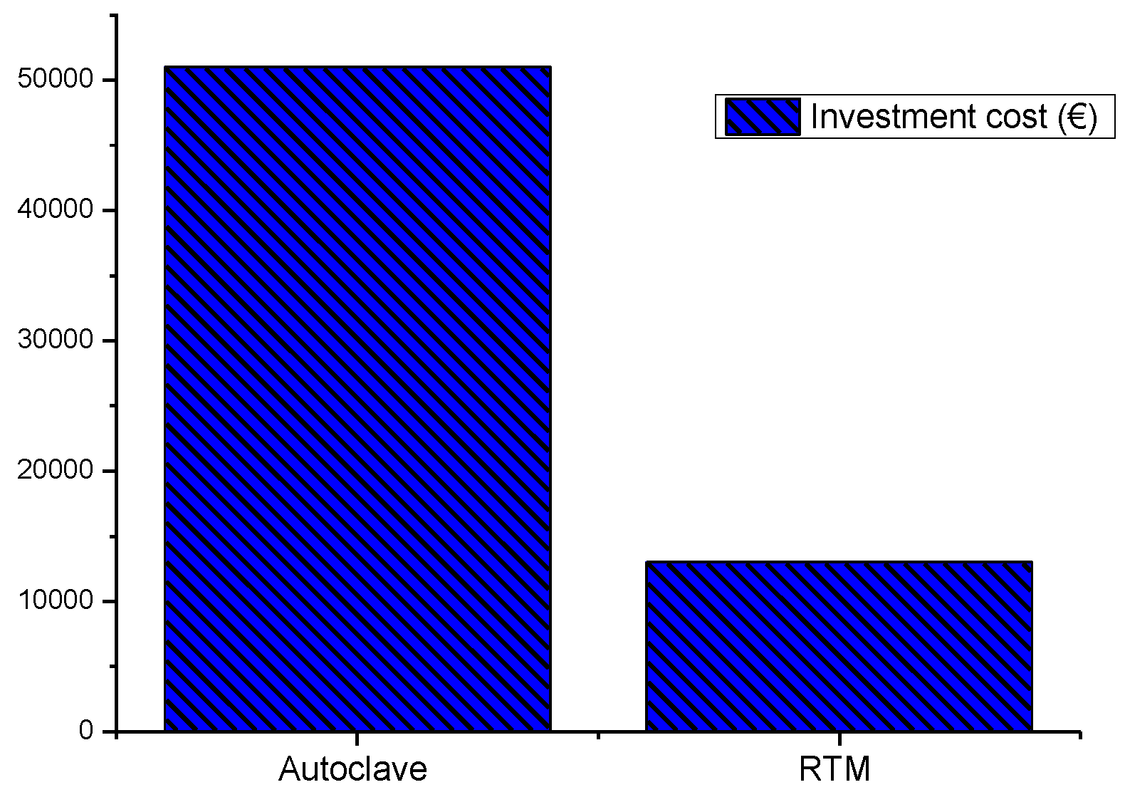
In this study, non-recurring costs are not taken into account. However, an effort is made to evaluate the equipment cost of autoclaving and RTM based on data available from a company specializing in online commerce (
www.alibaba.com).
4. Conclusions
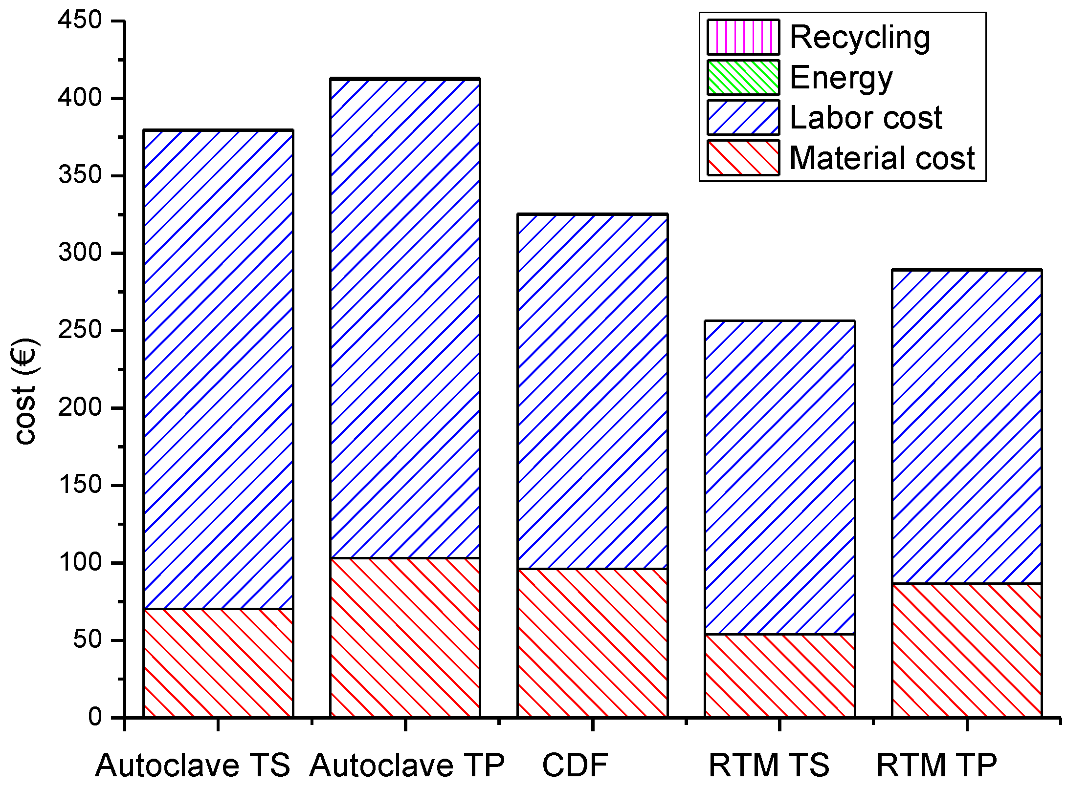
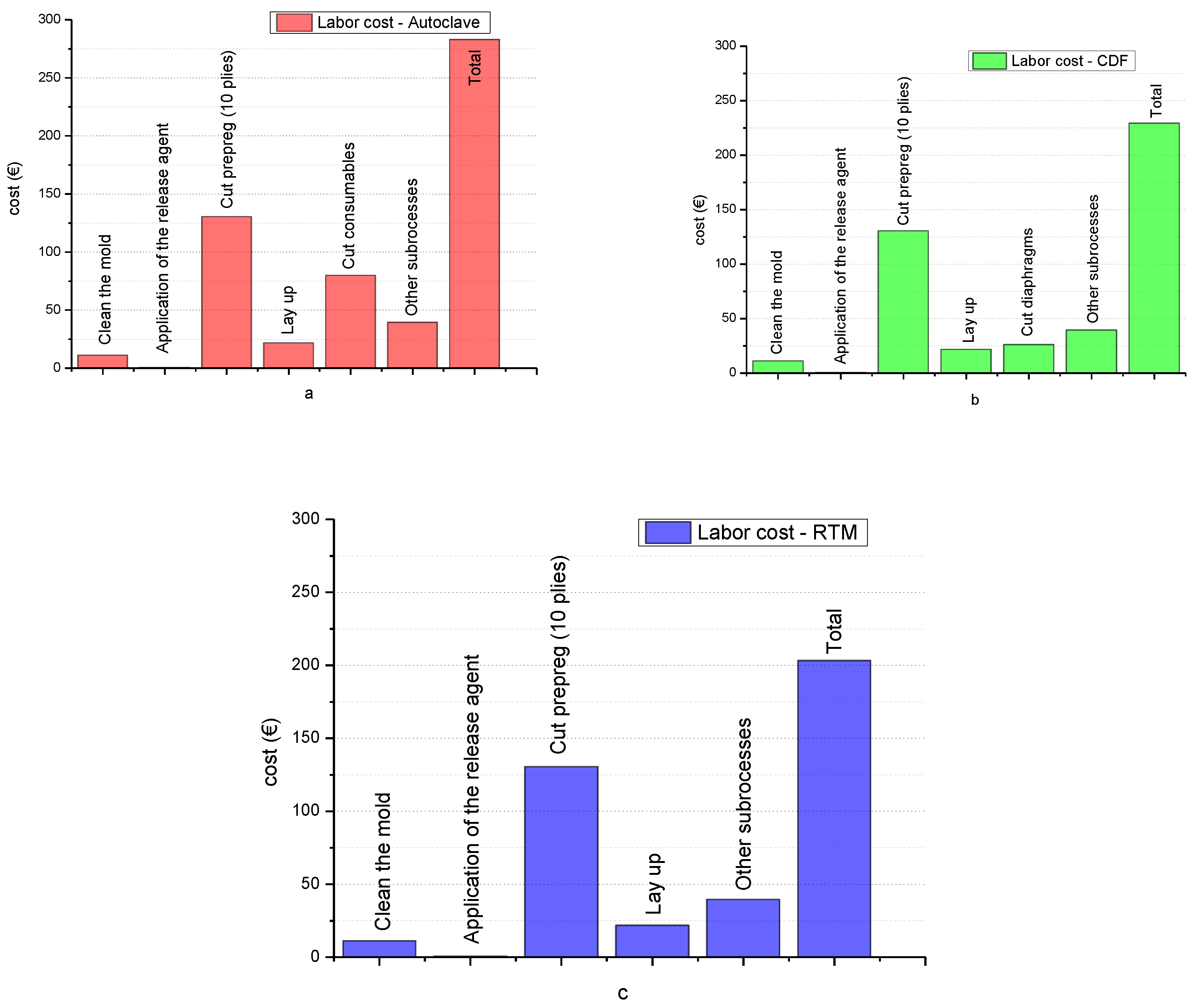
In the present work a Life Cycle Analysis (LCA) combined with a Life Cycle Cost (LCC) analysis was carried out to estimate the carbon footprint and financial efficiency of different material, manufacturing, and end-of-life scenarios associated with the production of an aeronautical composite structure: the canopy of the Twin Star helicopter. The results from the environmental analysis demonstrated that the embodied energy of the raw materials and the energy intensity of each process are the key factors affecting the carbon footprint, and are the cause of the lower ecological performance of PEEK composite compared with thermosetting epoxy composite. As far as the cost analysis is concerned, the main cost drivers are the cost of the materials (raw and auxiliary materials) and the cost for preparing the mold for the process.
However, parameters not taken into account in this study, such as higher product quality referring to increased mechanical properties and lack of defects provided by autoclaving; higher productivity offered by thermoplastic composites due to reduced processing cycles; assembling potential, such as the use of welding that is expected to lead to lower assembling costs and weight reduction, as well as recyclability can affect the decision strategy at the early design stages. This also underlines the need for a holistic approach to include potential reuse and ‘clear’ recycling applications of the composites, as well as circular economy considerations when establishing the criteria for designing an aircraft structure, selecting the material and finally manufacturing the structure.
Finally, this analysis makes evident the need for developing a versatile concept able to both deal with intricate tasks and provide the optimal design options among different alternatives.


