1. Introduction
Aircraft missions typically involve a number of phases, with varying operating conditions and a variety of requirements. It is desirable to optimise an aircraft to satisfy all mission requirements efficiently. Typically, the geometry would be optimised to complete the mission with a fixed planform. This leads to design compromise, to satisfy the requirements of the various flight phases. For example, an aircraft designed for loiter at low speed, where high speed dashes are preformed between loiter way-points, might favour a design that maximises the aspect ratio for the loiter condition, constrained by the requirements of the high speed dash, such as engine thrust, or power, or wing loading. This may lead to lower potential dash speed or shorter range and/or endurance. Furthermore, where the mission flight phase requirements vary widely, such as flight conditions that lead to incompatible wing loading requirements for a fixed wing, generally, additional systems, so-called “secondary high lift” systems, are required to modify the wing for these flight phases. These generally lead to discontinuities in the structure and aerodynamic boundary, which can lead to losses in aerodynamic efficiency.
The ability to modify the wing geometry, without discontinuities in the structure or aerodynamic boundary, could lead to improved mission efficiency [
1,
2,
3]. Morphing technologies are being considered to enable significant changes to the wing parameters and to improve the aerodynamic efficiency. Generally, morphing includes all technologies that enable the wing geometry to change [
4]; however, the contemporary use of morphing refers to technologies that enable significant modification to a “gapless” aerodynamic boundary through compliant structures and mechanisms.
Although aerodynamic performance morphing can potentially improve efficiency [
5,
6], because the structure uses compliant materials, the structural stiffness is generally reduced when compared to a fixed rigid structure with a hinge. The weight penalty incurred may render a concept non-optimum, as a fixed wing alternative may be aerodynamically inferior, but lead to better mission efficiency due to a comparably lighter structure.
Wing span and camber have a large effect on the aerodynamic performance and efficiency. Wing span is used to define the wing planform and has a significant impact on the maximum achievable aerodynamic efficiency for any flight condition. Morphing technologies implemented to modify span [
7,
8,
9,
10,
11,
12] can potentially greatly improve the mission performance [
13,
14]. However, span morphing concepts generally require significant modification to the primary load-bearing structure, such as the skin and spars used to carry bending moments and shear loads. Furthermore, the topology for other traditional structural components, such as wing ribs to reduce skin buckling, must be modified to accommodate the ability to vary the span. The additional structure may increase the weight and negate any aerodynamic improvements being realised for mission efficiency. Cross-sectional parameters, such as camber [
15,
16,
17], can be used to improve flight efficiency through improving the spanwise lift distribution. Modifications to the wing cross-section require potentially fewer structural compromises and less added mass than planform changes, but possibly offer only marginal gains in efficiency when compared to span morphing.
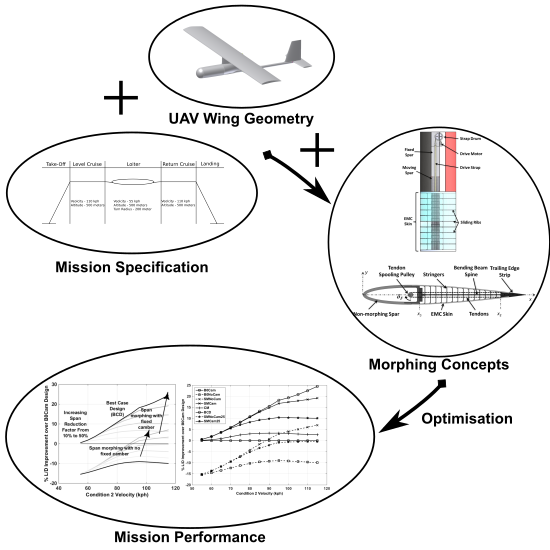
This paper presents an investigation into the potential aerodynamic performance and efficiency improvements that can be gained, using morphing technologies to modify the wing span or the cross-sectional camber. The example wing parameters used are representative of an unmanned aerial vehicle (UAV) that is rectangular, straight, untapered and unswept and used for a loiter mission, with low and high speed, constant altitude conditions. The study investigates the effect of the velocity range, the flight condition weightings and the maximum allowable span retraction on the overall aerodynamic efficiency for various morphing parameter and design optimisation strategies. This highlights the dependence that mission specification has on the viability of the morphing strategy to give the best potential improvement in overall flight efficiency. The effect of mass penalty is then investigated, to observe how this may affect which strategies are feasible. Alternatively, this can serve as a mass budget for the designers implementing the technology for a given mission specification.
The following sections present an overview of some example span and camber morphing concepts under consideration. From the description of these concepts, components in the analysis framework used to model and investigate these concepts are presented and described. Results using this framework compare the use of various combinations of morphing technologies and their effect on the mission performance.
2. Overview of AdAR and FishBAC
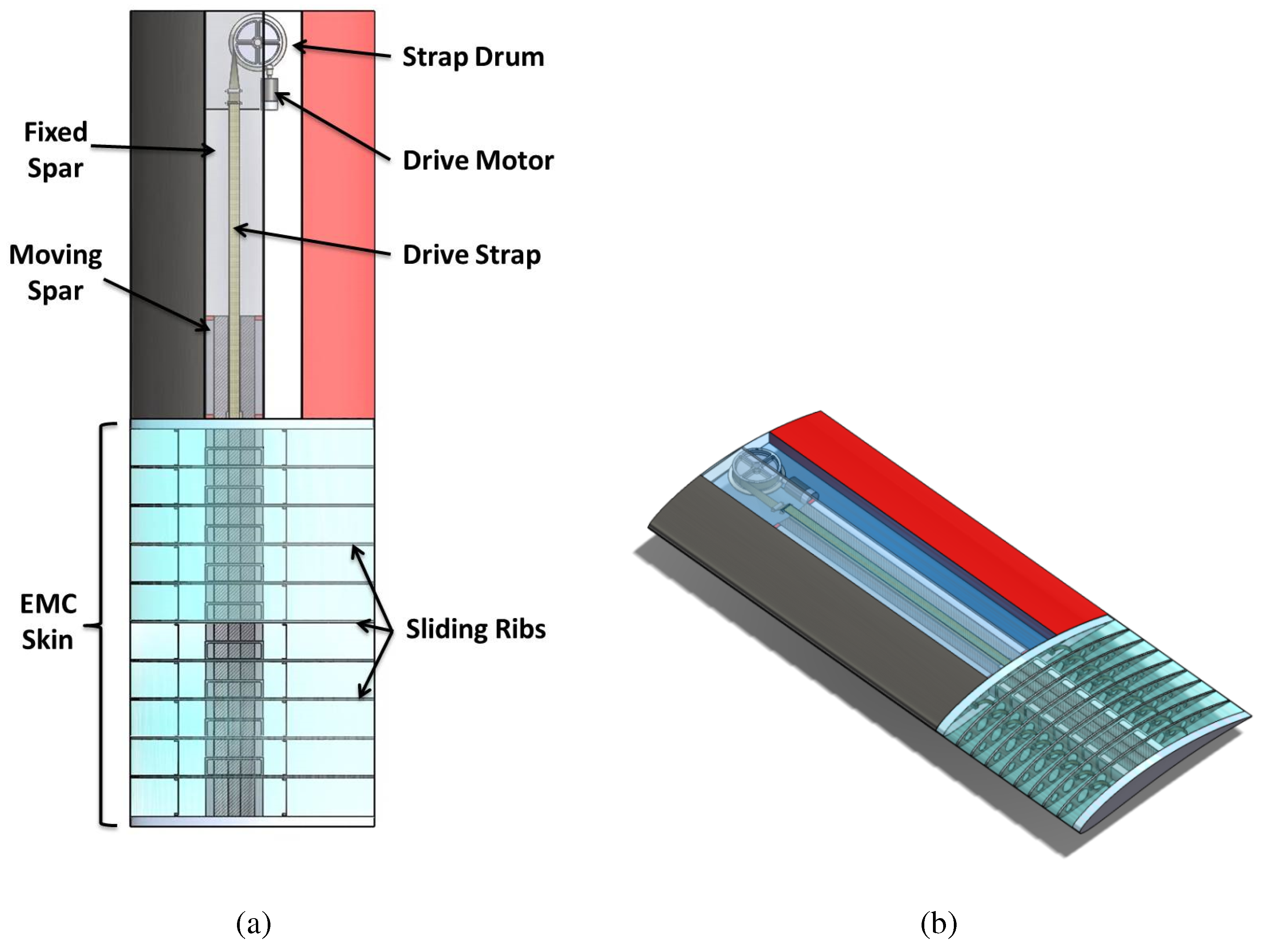
The adaptive aspect ratio (AdAR) wing is a span morphing concept under development at Swansea University [
12] that will form the basis of the span morphing wing analysis performed here. The concept combines four technologies to enable a 100% increase in the span of its morphing section; a compliant skin made from elastomeric matrix composite (EMC), a telescopic rectangular box spar, sliding ribs and a strap drive system. The arrangement of these elements in the morphing wing is shown schematically in
Figure 1a.
The AdAR wing concept incorporates a series of design approaches, which create a unique combination of features. The change in length required for the skin surface is achieved in this concept through material compliance. The elastomer matrix of the EMC composite is capable of achieving the high levels of strain required with a single continuous skin surface, removing the steps and discontinuities found with rigid sliding skin designs. A mechanism-based solution consisting of a telescopic sliding spar is proposed for the primary load bearing structure, due to its simplicity and low impact on actuation requirements. The discontinuous geometry of a telescopic spar does not have the same negative impact on aerodynamic performance as a discontinuous skin surface. In order to provide an effective interface between the stretching compliant skin and the sliding telescopic spar, the AdAR wing concept incorporates sliding ribs and a strap drive system. This is a tension-driven actuation system that connects the inner moving portion of the telescopic spar to the outer fixed portion, using a high strength fabric strap travelling around redirection pulleys in a manner that produces the extension of the spar using tension in the strap.
Figure 1.
Schematic of the adaptive aspect ratio (AdAR) span-morphing concept applied to a straight, unswept, untapered wing. (a) Top view of the AdAR wing concept, span extended; (b) isometric view of the AdAR wing concept, span retracted.
Figure 1.
Schematic of the adaptive aspect ratio (AdAR) span-morphing concept applied to a straight, unswept, untapered wing. (a) Top view of the AdAR wing concept, span extended; (b) isometric view of the AdAR wing concept, span retracted.
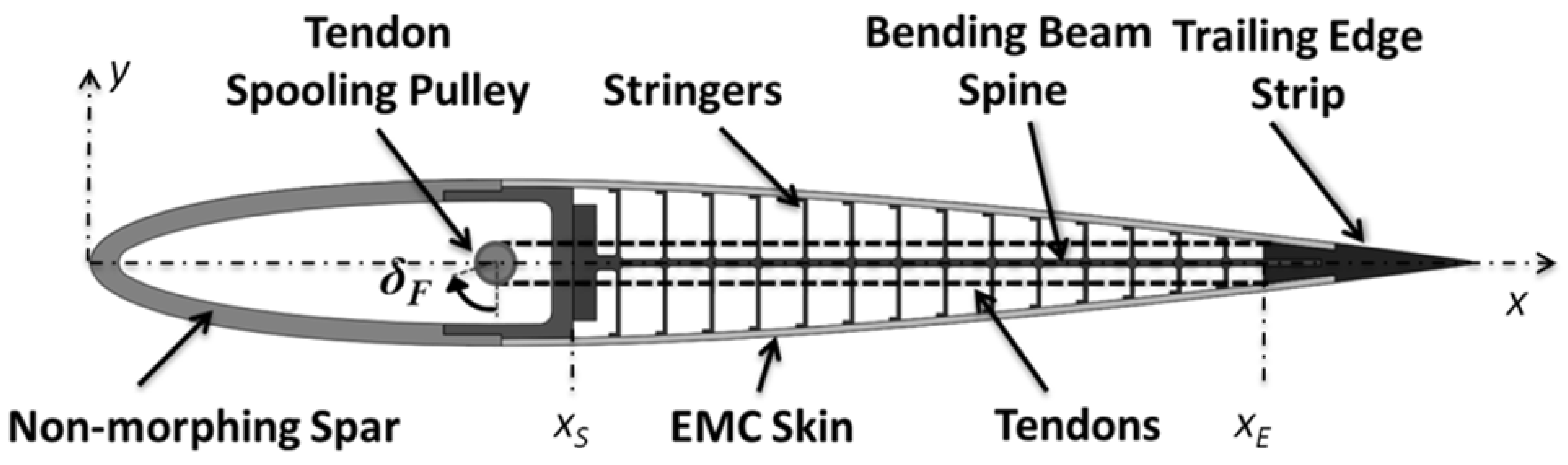
The fish bone active camber (FishBAC) concept is used to represent the camber morphing model in this paper. Introduced by Woods and Friswell [
5], this design employs a biologically-inspired compliant structure to create large, continuous changes in air foil camber and section aerodynamic properties. The structure, shown schematically in
Figure 2, consists of a thin chordwise bending beam spine with stringers branching off to connect it to a pre-tensioned EMC skin surface. Both the core and skin are designed to exhibit near-zero Poisson’s ratio in the spanwise direction. Pre-tensioning the skin significantly increases the out-of-plane stiffness and eliminates buckling when morphing. Smooth, continuous bending deflections are driven by a high stiffness, antagonistic tendon system. Actuators mounted in the non-morphing leading edge portion of the air foil (which constitutes the primary load bearing wing spar) rotate a drive pulley around which the tendons are spooled.
Figure 2.
The fish bone active camber (FishBAC) concept.
Figure 2.
The fish bone active camber (FishBAC) concept.
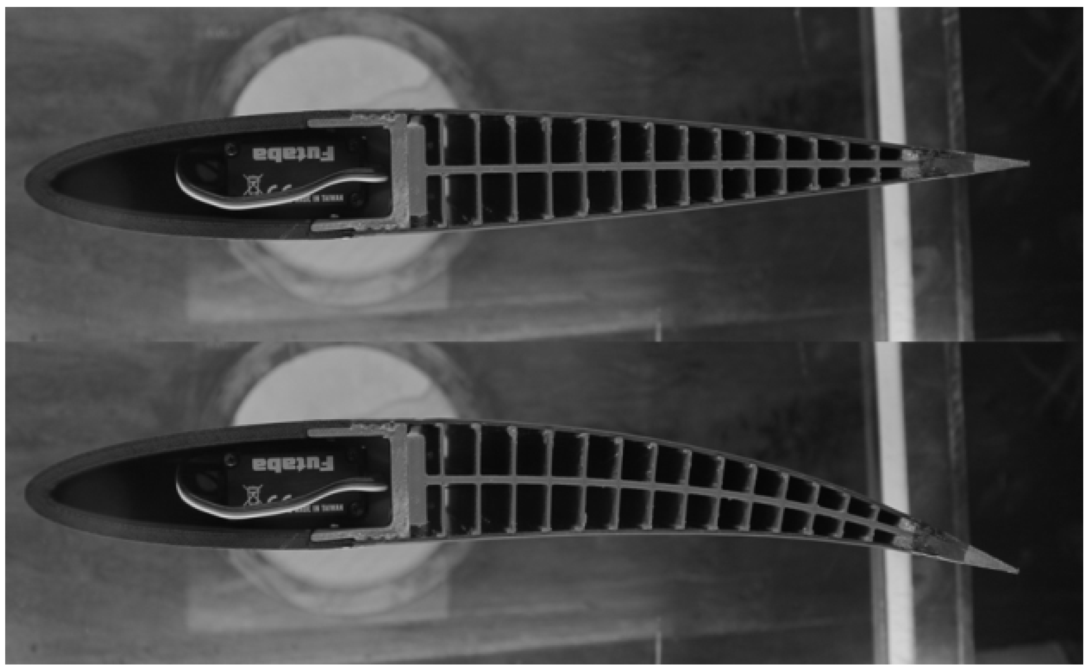
Wind tunnel testing of the prototype seen in
Figure 3 found that the FishBAC provided improved aerodynamic efficiency compared to traditional trailing edge flaps, with increases in the lift-to-drag ratio of 20%–25% being realized at equivalent lift conditions [
6]. An increase in the lift coefficient of
= 0.72 between unmorphed and morphed was measured at a free stream velocity of
= 20 m/s and an angle of attack of α = 0°, and this
was maintained over the entire non-stalled range of alphas.
Figure 3.
FishBAC wind tunnel test model showing baseline and morphed shapes.
Figure 3.
FishBAC wind tunnel test model showing baseline and morphed shapes.
The large achievable deflections and continuous compliant architecture make this concept potentially applicable to fixed wing applications ranging in scale from small UAVs to commercial airliners and to rotary wing applications, including wind turbines, helicopters, tilt-rotors and tidal stream turbines. As such, the FishBAC and AdAR are considered viable candidates for the following investigation.
3. Methods and Models
In this section, the methods used to develop the analysis framework are described, as well as the models used to represent the design parameters for the wing and morphing concepts. This includes the potential flow solver used to compute the lift and lift-induced drag and a low-fidelity wing drag tool to estimate the skin-friction drag. Models for the span and camber morphing concepts are also introduced, together with the baseline wing used in the analysis and the mission efficiency or flight performance objectives.
3.1. Aerodynamics: Vortex Lattice Solver
The Navier–Stokes equations give a complete mathematical description of the variables required to model the aerodynamics of a flow. Typically, these equations are computationally expensive to solve and are generally not used extensively in the design phase. Often, the Navier–Stokes equations are reduced to an inviscid, incompressible set of equations, which are solvable by a potential flow method [
18]. The vortex lattice solver, Athena Vortex Lattice (AVL), developed by Mark Drela and Harold Youngren at MIT, is the potential flow method used to compute aerodynamic data. This theory is used to solve the boundary element problem, solving the equations at the boundaries of the domain of interest. On the boundaries of the domain, the Laplace equation is satisfied, and therefore, this excludes the thin boundary layer or separated flow. This layer contains significant vorticity, limiting application to an infinitesimal distance from the boundary layer edge.
For well-behaved, incompressible flow, the lift and induced drag can be predicted with reasonable confidence. A method is required to estimate the skin friction component, as potential theory does not account for the viscous component of drag.
3.2. Aerodynamics: Low-Fidelity Wing Drag
A major component of drag comes from the effects of viscosity. Whilst the lift-induced drag coefficient tends to reduce at high speeds, as these correspond to low-lift coefficients, the relationship between the viscous drag coefficient and speed is more complex due to the Reynolds’ number-dependent nature of the boundary layer. However, at higher speeds, the viscous drag component often becomes the more significant and must be included in any optimisation and performance calculations. Without the viscous drag component, an optimiser will tend to pick high-speed flight conditions to minimise lift-induced drag.
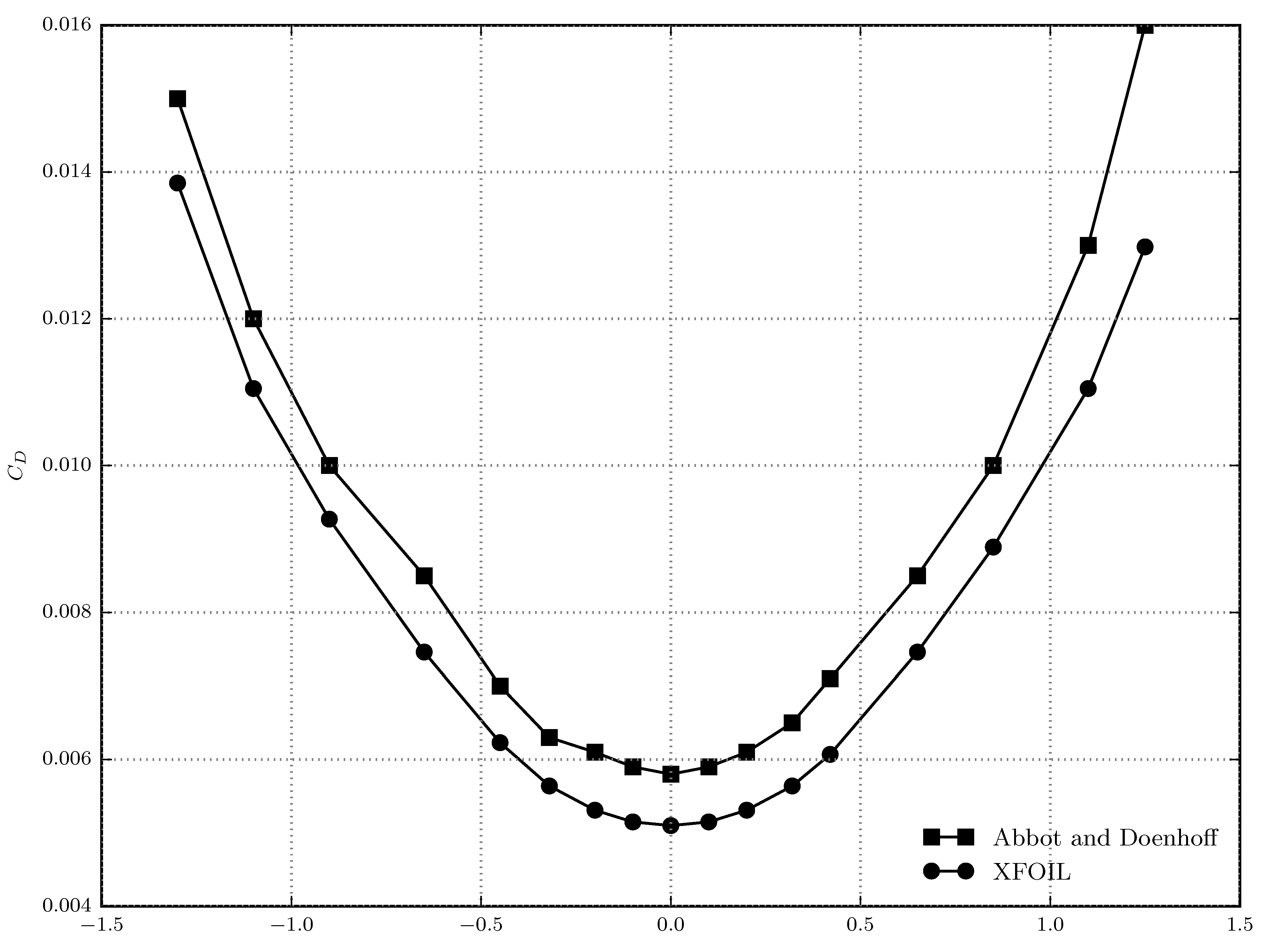
Unfortunately, accurate prediction of viscous drag is difficult and depends on laminar-turbulent transition freestream turbulence and surface roughness. Approximate and semi-empirical models have to be used for turbulence. Many of the analysis techniques that model these effects directly, such as Reynolds averaged Navier–Stokes (RANS) computational fluid dynamics (CFD) and large eddy simulation (LES), are too computationally intensive for this current study, where many geometries and different flight conditions are considered. To balance computational effort and fidelity, a tool was developed that utilises the XFOIL 2D code for aerofoil viscous drag prediction. Strip theory is then used to integrate this drag component across a discretised wing.
XFOIL uses a high-order panel method to solve the flow-field around a 2D aerofoil. A viscous boundary layer method is also included to help improve drag prediction accuracy. This uses a two-equation lagged dissipation integral formulation, with an
transition model [
19]. In general, this method shows good accuracy for cambered aerofoils when compared to experimental results, such as those from [
20]. An example at a Reynolds’ number of
for an NACA 0012 aerofoil can be seen in
Figure 4. Similarly, when laminar-turbulent transition was forced in past work, XFOIL was shown to compare well to turbulent CFD cases [
21].
Figure 4.
A comparison between experimental results [
20] and XFOIL for an NACA 0012 aerofoil at RE=
, with natural transition.
Figure 4.
A comparison between experimental results [
20] and XFOIL for an NACA 0012 aerofoil at RE=
, with natural transition.
To obtain the final lift and drag predictions, the wing geometry is first discretised into panels. These are then used to create a geometry that is passed to AVL, which then solves the inviscid flow field to provide the desired overall wing lift coefficient. AVL then produces a strip-force file, containing the local value of the lift coefficient at the centre of each spanwise panel. Given these data, XFOIL is then used to calculate the viscous drag in each spanwise strip using the Reynolds number and local aerofoil shape. Finally, the drag is integrated over the wing strips.
3.3. Morphing Shape: Span (AdAR)
The AdAR concept proposes a compliant skin, which enables a pseudo-continuous, gapless aerodynamic boundary to the wing structure. This potentially reduces forms of drag and loss in lift associated with discontinuities in the aerodynamic boundary. The span (
b) is assumed to vary with the nondimensional span actuation parameter (
):
This model allows an initial span to be selected (); a span scaling factor () is applied to represent the maximum allowable change in the original span and an actuator setting parameter () that varies from zero (minimum span) to one (maximum span).
3.4. Morphing Shape: Camber (FishBAC)
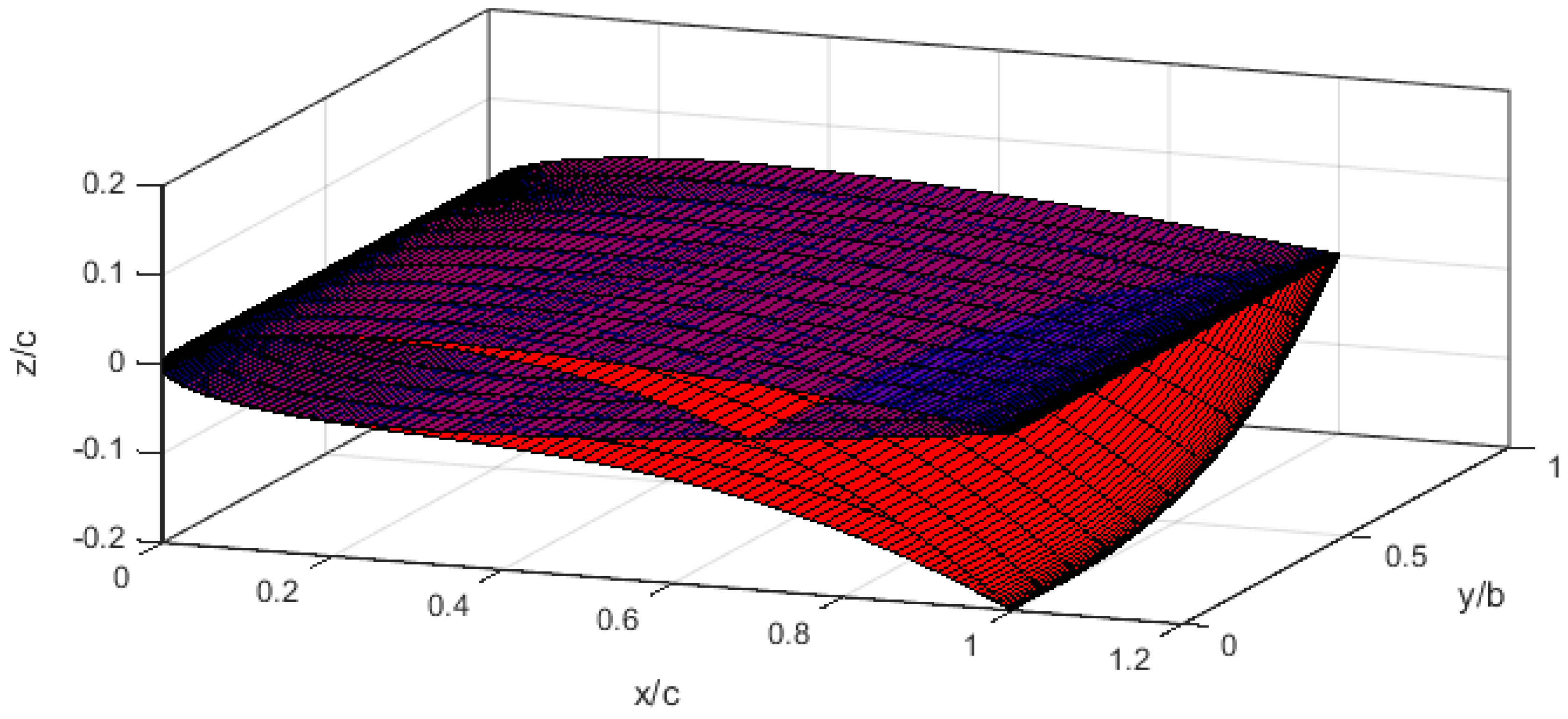
The model used for FishBAC uses a third-order polynomial to model the camber for each cross-section. This form provides a fair representation of the achievable shape obtainable by the concept under consideration. Additionally, a third order polynomial is used to describe the spanwise distribution of the trailing edge tip deflection, which is the vertical displacement of the trailing edge of a cross-section from its nominal position. The non-dimensional spanwise shape, based on the equation presented in Fincham [
22], is defined as:
is the non-dimensional tip deflection, which varies along the span, with the maximum deflection at the root, and zero at the tip. This is a cubic function and varies with the normalised spanwise position,
.
z is the tip deflection, and
c is the chord.
defines the non-dimensional camber line and is the product of the maximum obtainable tip deflection (
), the actuator setting (
), which varies from zero to one, and the spanwise non-dimensional tip scaling factor (
).
These functions enable the camber and its spanwise distribution to be modelled smoothly, representing the gapless continuous shape enabled by the concept.
Figure 5 presents the chordwise shape and spanwise tip distribution with the actuator set at 20% of chord length.
Figure 5.
Representation of FishBAC spanwise and chordwise equations
Figure 5.
Representation of FishBAC spanwise and chordwise equations
3.5. Morphing Wing Parameters
The model used in this investigation is based on a modified Tekever AR4 with wing dimensions presented in [
1,
23,
24]. The platform has an approximate take off mass of 25 kg; the wing has a nominal span of 4 m and an aspect ratio of 6.67.
Figure 6 presents a schematic of the wing parameters that will be used throughout this investigation.
Figure 6.
Schematic of the wing, including wing parameters.
Figure 6.
Schematic of the wing, including wing parameters.
The baseline wing has an NACA 0010 aerofoil, with a span of 4 m and a chord of 0.6 m. From this baseline, either additional span or camber is added. The camber variation Equation (
2) produces an equivalent camber close to an ideal spanwise twist distribution for an elliptical lift distribution, which is optimum to minimise the lift induced drag. This is to simplify the analysis and to determine the effect mission parameters and mass penalties have on the final result.
3.6. Mission Efficiency and Improved Range Estimation
Measuring the performance of morphing systems presents a challenging task. Morphing concepts integrated into aerospace systems have the capacity to improve aerodynamic performance by enabling the geometry to adapt to different flight conditions and to maximise the potential performance by modifying the geometry. However, these concepts commonly use mechanisms and/or compliant materials in order to enable the structure to undergo significant strain to achieve shape modification. Generally, this leads to an increase in weight and/or reduction in structural stiffness, thereby reducing structural or weight efficiency. This may reduce the overall flight or mission performance.
The primary difficulty when estimating the performance of a morphing concept in comparison to a conventional aircraft system is the prediction of the mass of the concept. Although morphing allows the geometry to improve the aerodynamic performance through shape optimisation, as the global mission performance is, in general, also a function of mass, any improvement in aerodynamic efficiency may concurrently lead to losses in weight efficiency. The constant altitude range equation for cruise at constant weight is [
25]:
where
R is range,
W is the work done by the power plant,
is the aerodynamic efficiency,
is the nominal mass and
λ is the fractional increase in mass penalty
. With a nominal fixed weight chosen for the morphing and non-morphing results and assuming that the propulsive efficiency is equivalent (
i.e.,
W represents the work done and is equal and constant for all configurations), the range is dependent on the aerodynamic efficiency and mass. This enables direct comparison of various morphing and non-morphing configurations. The mission represented in this study investigates the effect of various morphing strategies over two weighted flight conditions. The overall ‘mission’ performance is computed as:
where
represents the weighted aerodynamic efficiency of condition
and condition
, where
is the percentage of weighting and
the aerodynamic efficiency of
; for example, where
%,
% and Equation (
5) becomes
. This is sufficient to estimate the change in total range that can be achieved for varying mission weighting.
Typically, morphing introduces discontinuities in the structure or reduced stiffness due to the structural topology and material selection required to enable morphing. As a result, more material mass may be required to provide equivalent structural properties to resist the loads. This is reflected by including increased mass compared to the non-morphing, nominal mass. Thus, the new range-based objective that includes the effect of mass penalty on the mission performance is:
From these equations, the effect on range can be estimated, which is normalised by the fixed non-morphing design value to show the effect of morphing.
The drag for these results includes the inviscid and viscous drag of the wing, computed by the AVL and low-fidelity wing drag (LFWD) tools, respectively. This neglects the trim drag, which describes the drag attributed to the whole aircraft system and is affected by details, such as configuration selection. Trim drag can be seen as a measure of the drag induced by design features and the interaction of various components modelled on the aerodynamic boundary. Generally, as well as the lift generated on the wing, an unresolved pitching moment is generated. Linear aerodynamics predicts that this is approximately constant about the lifting surface mean aerodynamic chord and is dependent on the wing planform and cross-sectional properties. Generally, for positive cambered aerofoils, a nose down pitching moment is induced. For a conventional tail-aft, stable platform, this requires negative lift to provide moment equilibrium and to balance the aircraft. This, in turn, requires the wing to generate more lift, inducing more drag, and, as such, is a source of inefficiency. To reduce this required additional lift, it is desirable to increase the tail moment arm, which is not necessarily desirable for either mass or stability. However, the tail moment arm must also not be too short, as the tail will then be operating in the wing downwash, leading to inefficiency through moment generation for balance. Non-conventional tail-fore configurations balance these negative moments through positive lift, which is beneficial to avoid “parasitic lift”. However, this leads to downwash on the wing, thus reducing the efficiency of the lift production of the wing and, therefore, reduces the global aerodynamic efficiency.
Because the trim drag is highly dependent on configuration selection and design features, and is sensitive to parameter values, to accurately compare the effect of morphing would require the configuration selection, empennage design and parameter estimation to be optimised for each candidate. Alternatively, categories of aircraft configurations could be created to investigate the effect of morphing on each. However, this is beyond the scope of this paper, which presents a less detailed, simpler investigation, to expose the performance benefits of camber and span morphing on an isolated lifting surface, which assists the designer in decisions when considering morphing on a potential candidate.
4. Results
The results generated for this paper include parameter sweeps and optimisation results of the model. The model limits are presented in
Table 1.
Table 1.
Model limits.
| Parameter | Min | Max | Inc. |
|---|
| (kph) | 50 | 115 | 5 |
| 0.1 | 2.1 | 0.1 |
| Span (m) | 1 | 14 | 0.05 |
| Camber (% tip deflection to chord) | −0.3 | 0.05 | 0.0 |
A number of configurations were tested, with varying degrees of morphing shape change and different baseline designs. The following cases are considered:
Basic non-morphing, unmodified (B0NoCam): an uncambered wing (fixed
and
), with optimised span (fixed
and
, optimised
) over the two selected flight conditions within the range presented in
Table 1 for maximum aerodynamic efficiency.
Basic non-morphing cambered (B0Cam): a wing with a fixed camber distributed according to the third order polynomial (fixed and a fixed across two flight conditions) and span optimised for maximum aerodynamic efficiency over both flight conditions (fixed and , optimised ).
Span morphing, no camber (SMNoCam): a morphing uncambered (fixed and ) wing with optimised initial span and morphed positions (optimised for each flight condition and fixed, optimised ) to maximise the mission aerodynamic efficiency; the maximum allowable span modification is determined by the span modification factor ().
Span morphing with initial camber (SMCam): a morphing cambered wing (fixed and a fixed across two flight conditions) with optimised initial span (fixed ), camber and morphed positions (optimised for each flight condition and fixed) to maximise the mission aerodynamic efficiency; the maximum allowable span modification is determined by the span modification factor.
Camber morphing (CM): a morphing wing capable of camber change from the root (fixed across two flight conditions with optimised for each flight condition), where the baseline span is optimised (optimised across two flight conditions, fixed and optimised for each flight condition) to maximise the mission performance over the two flight conditions.
Best case design (BCD): the best wing span and camber parameters for each independent flight condition (fixed across two flight conditions with optimised for each flight condition, fixed and optimised for each flight condition, with optimised and fixed across both flight conditions); this should supply the maximum bounded potential performance capacity for the parameters used.
The non-morphing and unbounded best-case design give an envelope from which morphing can be assessed. The baseline performance selected is the optimised basic fixed wing with camber candidate, as this represents the best achievable performance with no morphing deployed. This is the candidate for each optimisation used to normalise the results.
The following results are generated using a surrogate model of the data generated by the framework presented in
Section 3. The optimisation is performed using the
fminicon function within MATLAB, where parameter limits of the morphing model give the constraints. The optimisation for the morphing configuration first allows the design parameters to be set (baseline span
, and if fixed camber is implemented, then
), from which the morphing parameter for the two conditions is set to optimise Equation (
5) or Equation (
6). For each optimum setting, the lift is balanced through varying the angle of incidence for the candidate wing. The mission speeds (
) and densities (
ρ) or dynamic pressure (
) and weightings are fixed for each data point and optimised design.
4.1. Nominal Results and Parameter Sweeps
The nominal results present the aerodynamic efficiency variation for the minimum velocity and maximum velocity condition, where the span and camber are varied. This is presented in
Figure 7.
Figure 7.
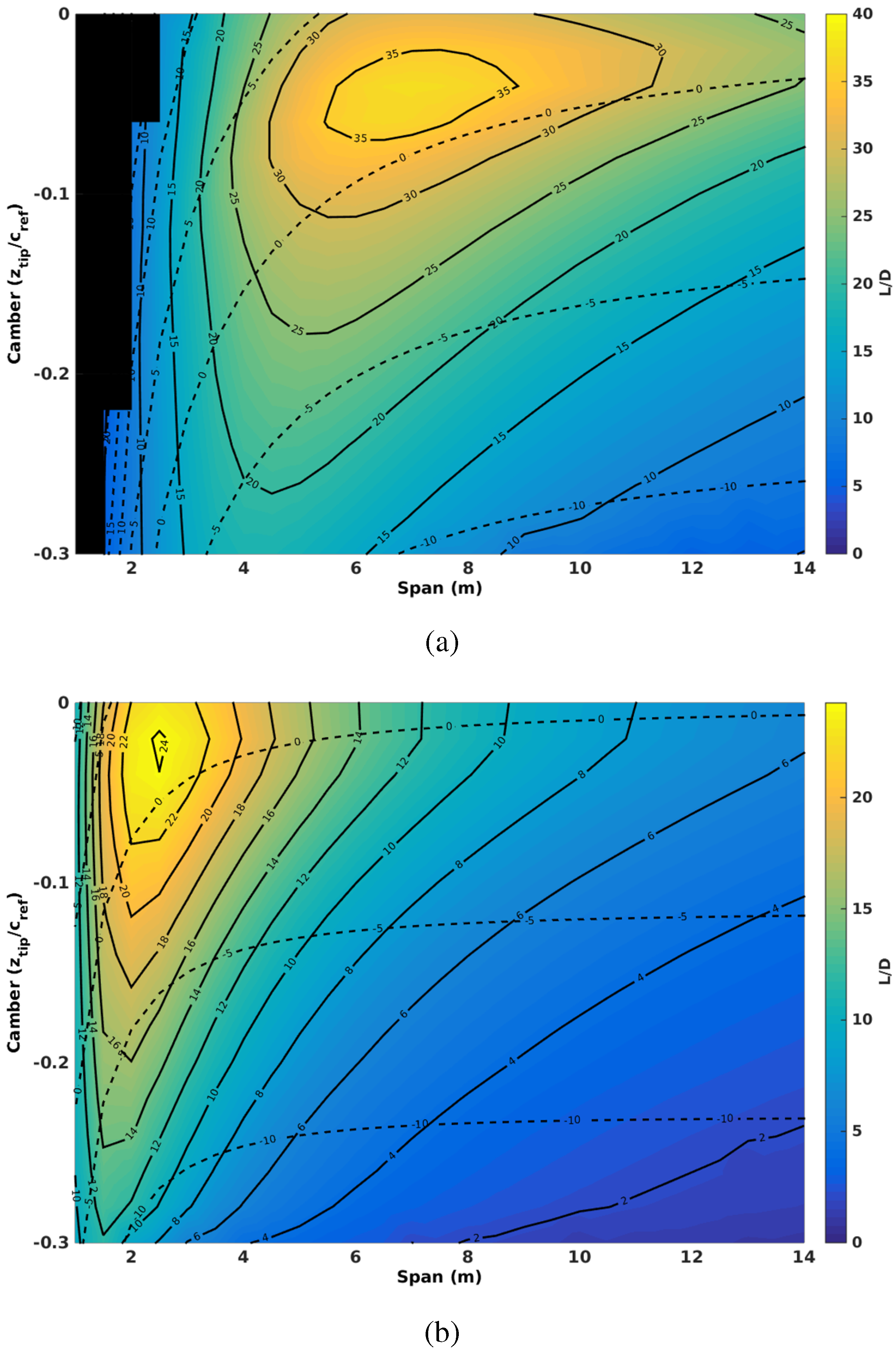
Nominal parameter sweeps for camber and span for the minimum and maximum speed flight conditions, where the colour map and solid contours represent aerodynamic efficiency and the dashed contours represent the required angle of incidence to trim the lift of the wing. (a) Parameter sweep at 50 kph; (b) parameter sweep at 115 kph.
Figure 7.
Nominal parameter sweeps for camber and span for the minimum and maximum speed flight conditions, where the colour map and solid contours represent aerodynamic efficiency and the dashed contours represent the required angle of incidence to trim the lift of the wing. (a) Parameter sweep at 50 kph; (b) parameter sweep at 115 kph.
Figure 7a shows the low-speed condition of 50 kph. The optimum span and camber is a span of 7 m and a root tip deflection of 5% of chord with a maximum L/Dof 36.
Figure 7b shows the aerodynamic efficiency at the high speed condition of 115 kph. The maximum achievable aerodynamic efficiency has decreased to 24, a loss of 1/3, and the optimum is located at a span of 2 m, a decrease of 2/3, and camber of 2% at the root, half of the low speed condition. In terms of morphing, a change of 2% in the tip deflection for the FishBAC concept is a very manageable change, while a span reduction of 66% or an increase of 200% is far more difficult to achieve and impossible in a single-stage span morph with the proposed AdAR concept. The optimum aerodynamic efficiency occurs at an angle of incidence of 2–3 degrees in both cases.
Figure 8.
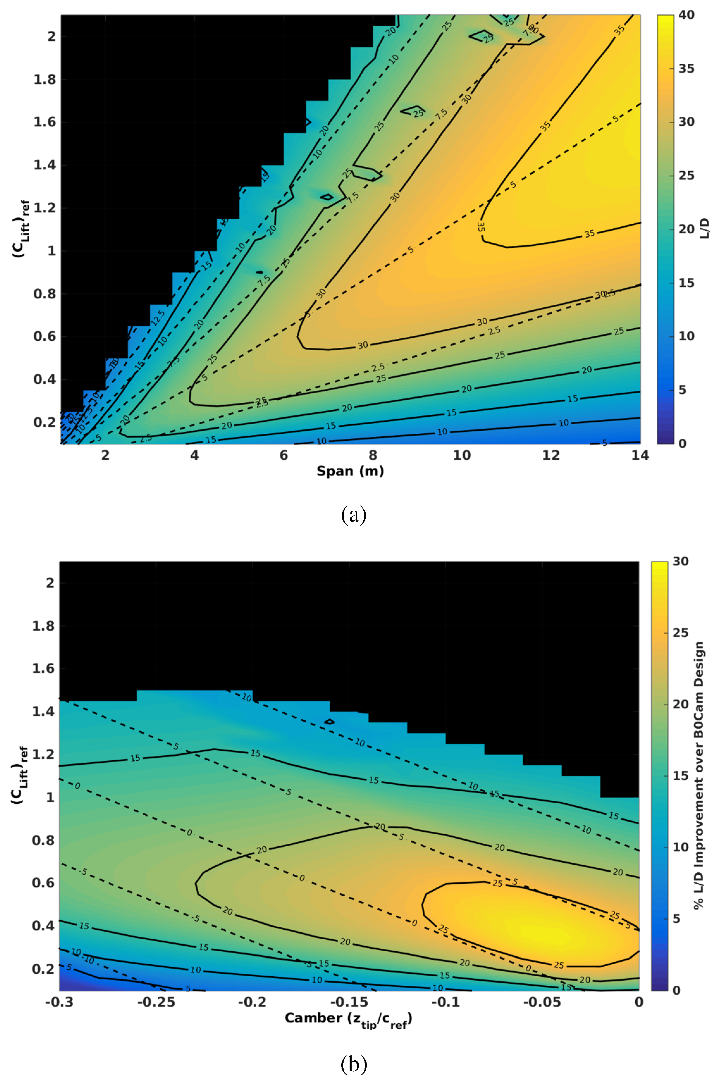
Representative data for nominal parameter sweeps of lift coefficient and camber or span for . The colour map and solid contours indicate the aerodynamic efficiency, where dashed contours indicate the operating angle of incidence. (a) Effect of span and lift coefficient with zero camber; (b) effect of camber and lift coefficient with a span of four meters.
Figure 8.
Representative data for nominal parameter sweeps of lift coefficient and camber or span for . The colour map and solid contours indicate the aerodynamic efficiency, where dashed contours indicate the operating angle of incidence. (a) Effect of span and lift coefficient with zero camber; (b) effect of camber and lift coefficient with a span of four meters.
Figure 8a presents the aerodynamic efficiency for varying span and operating reference lift number at zero camber, where
Figure 8b shows the variation with varying camber and operating lift number at nominal span (
m). The operating lift number is defined by
, where
is the velocity and ρ is the density, and the reference area
is fixed even in the presence of span morphing.
Figure 8a presents the independent effect of span and lift (or reference lift coefficient) on the aerodynamic efficiency. The contours indicate that as the span increases, the maximum aerodynamic efficiency increases and the optimum reference lift increases. The maximum aerodynamic efficiency, as was observed in the results in
Figure 7, occurs at approximately a constant angle of incidence between four and five degrees. These data also indicate that as the span increases, smaller increases are observed in the maximum aerodynamic efficiency obtainable. The implication of
Figure 7 and
Figure 8a is that for a fixed concept, optimised for a single flight condition, larger spans enable greater variation in the lift coefficient for a practical range of angle of incidence.
Figure 8b shows the variation in aerodynamic efficiency for a constant span of 4 m. This shows that camber can be used to control the lift and optimised with the operating angle of incidence for the optimum aerodynamic efficiency. Generally, the maximum performance is determined by a particular camber-span combination for a given operating lift coefficient, where the capacity is largely determined by the span.
4.2. Optimisation Results
The optimisation results are presented for the various design descriptions outlined in
Section 4. Before any meaningful investigation into the various designs, the maximum possible performance at each flight condition is presented in
Figure 9a, for the optimum span and camber given in
Figure 9b.
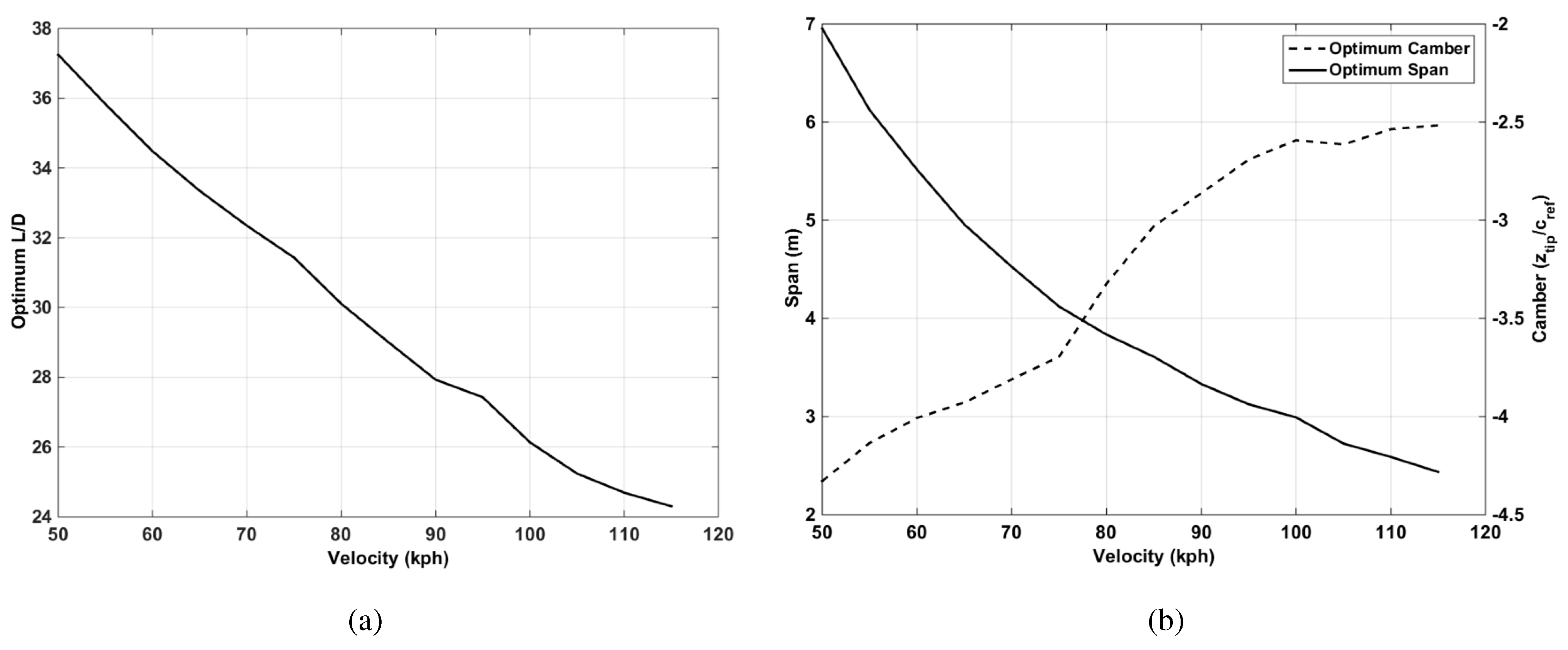
Figure 9.
Optimum parameters for the speed range from 50–115 kph. (a) Optimum aerodynamic efficiency; (b) optimum span and camber.
Figure 9.
Optimum parameters for the speed range from 50–115 kph. (a) Optimum aerodynamic efficiency; (b) optimum span and camber.
The maximum possible aerodynamic efficiency decreases continuously as the speed increases. Generally, as the operating speed increases, the optimum span reduces, as does the required camber. The data presented in
Figure 10,
Figure 11,
Figure 12,
Figure 13,
Figure 14,
Figure 15,
Figure 16,
Figure 17,
Figure 18 and
Figure 19 show results where the mission velocities for low speed and high speed are varied. To simplify the presentation of the results, either the low speed is fixed at its minimum value or the high-speed condition is fixed at its maximum value, and the other is varied from its minimum to maximum value according to
Table 1 on the X-axis.
Figure 10 presents an overview of the optimisation runs for all configurations. A 50%–50% weighting is applied to the low- and high-speed condition when computing the mission objectives according to Equations (
5) and (
6).
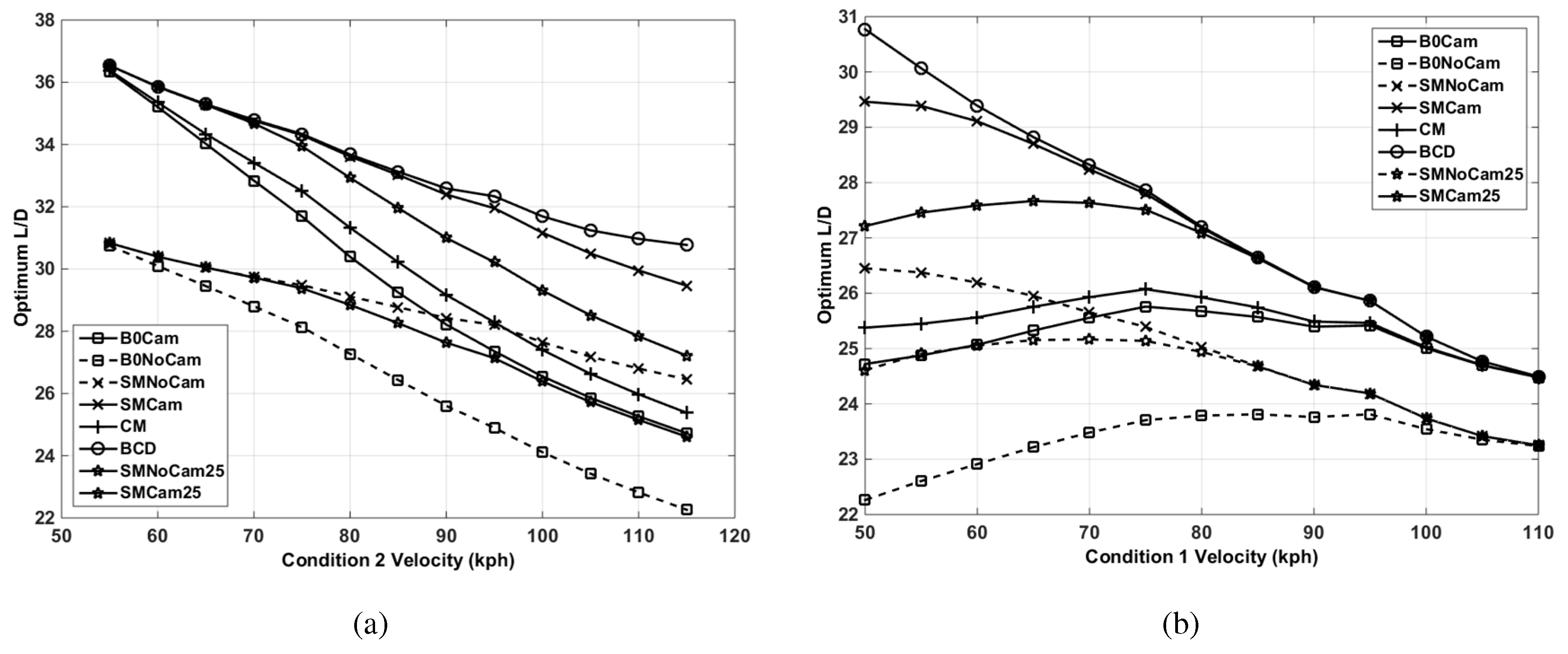
Figure 10.
Aerodynamic efficiency for the designs over variable speed ranges. (a) Aerodynamic efficiency for low speed fixed at 50 kph; (b) aerodynamic efficiency for high speed fixed at 115 kph.
Figure 10.
Aerodynamic efficiency for the designs over variable speed ranges. (a) Aerodynamic efficiency for low speed fixed at 50 kph; (b) aerodynamic efficiency for high speed fixed at 115 kph.
In
Figure 11, these are normalised by the best fixed design to give an indication of where morphing performs better aerodynamically than a fixed wing with optimised span and camber.
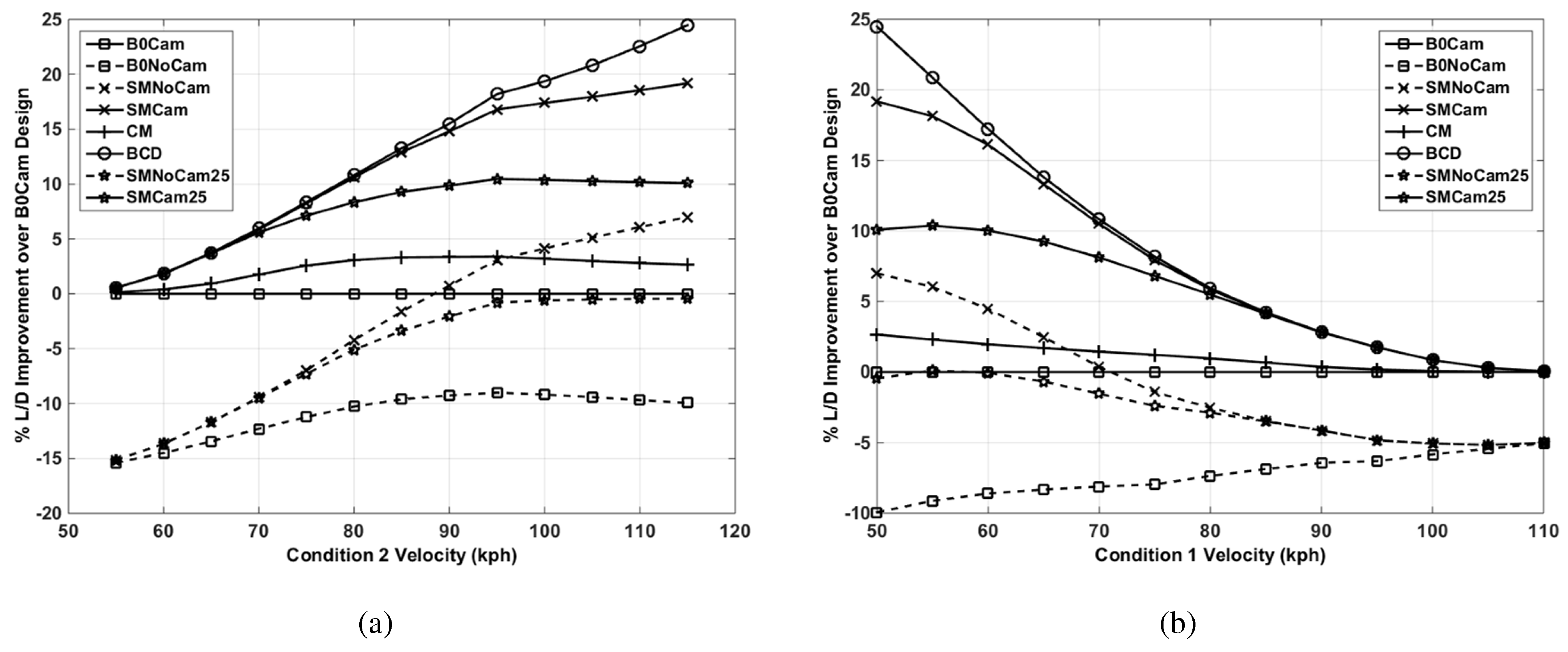
Figure 11.
Aerodynamic efficiency for designs over variable speed ranges normalised to the baseline camber design. (a) Aerodynamic efficiency for low speed fixed at 50 kph; (b) aerodynamic efficiency for high speed fixed at 115 kph.
Figure 11.
Aerodynamic efficiency for designs over variable speed ranges normalised to the baseline camber design. (a) Aerodynamic efficiency for low speed fixed at 50 kph; (b) aerodynamic efficiency for high speed fixed at 115 kph.
Consider first the effect of camber. The results for the fixed design, the fixed design with camber and the results for the span morphing design and the span morphing with camber show that the effect can be quite dramatic, with the optimised camber designs performing significantly better. It can also be seen that the camber morphing design follows closely the same trend as the fixed cambered design, with marginally increased performance. This is because camber morphing allows the maximum aerodynamic efficiency for a fixed span to be located in the camber envelope, for multiple conditions within a mission (see
Figure 8b), where the non-morphing design must compromise between the flight conditions for the best mission performance with a fixed camber. Span morphing without optimising the root camber does not work for a majority of the mission speed ranges shown, where the addition of a fixed camber is shown to be the optimum morphing strategy over all speed ranges. This implies that the span is largely responsible for setting the maximum aerodynamic efficiency potential over a mission. Reducing the allowable span retraction (SMNoCam25 and SMCam25) from 50% down to 25% shows a decrease in the aerodynamic efficiency, where the non-cambered span retraction is shown to perform worse than a fixed cambered baseline over all velocity ranges for the 50–50 mission weighting. A 50% retraction is the maximum single-stage span retraction, whereas the 25% reduction presents a more realistic, achievable span reduction. The likely span retraction and performance should be bounded by this envelope.
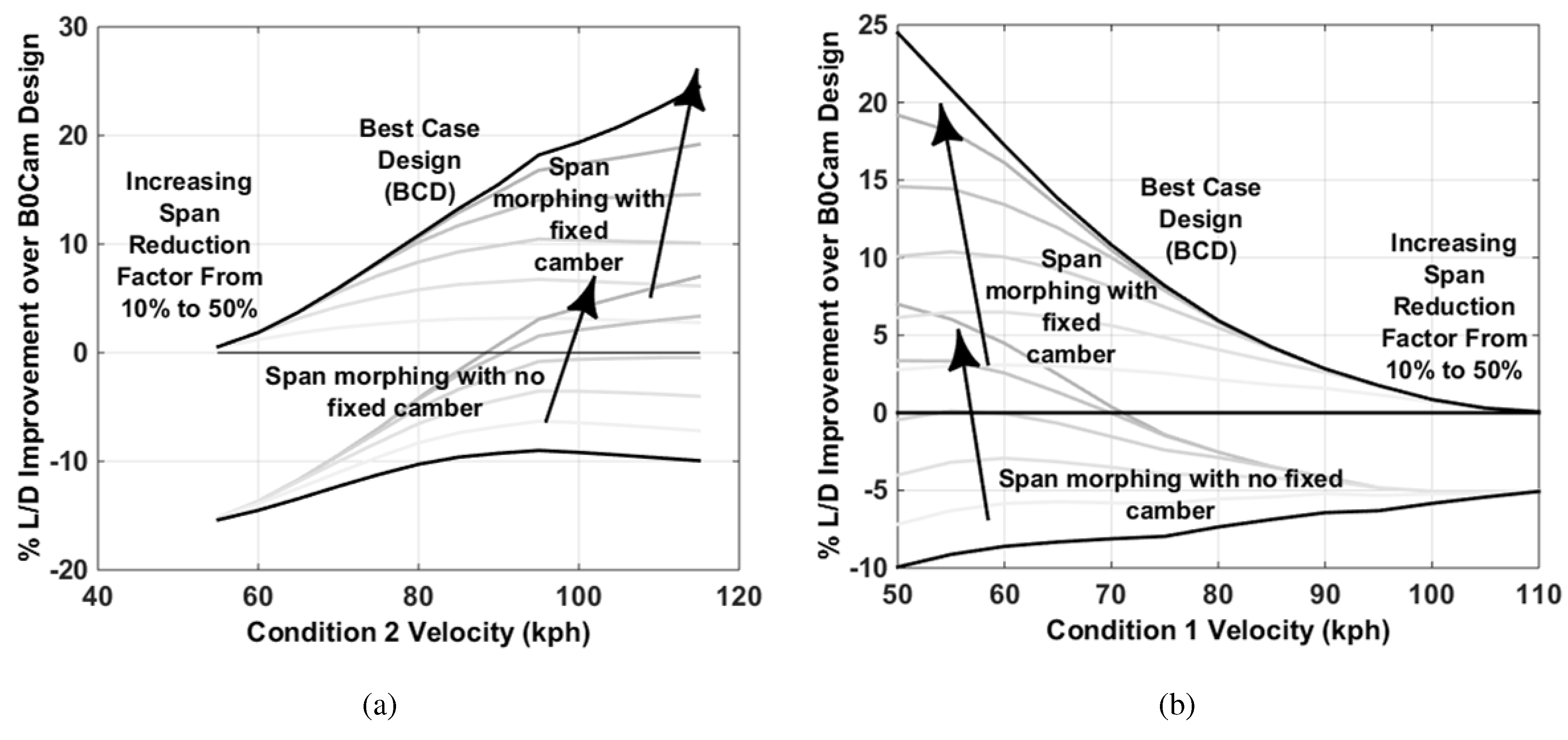
Figure 12 shows the effect of reducing allowable span retraction on the non-cambered and cambered design strategies.
The following sub-sections show the effect of mission weighting for different velocity ranges and, in the case of span morphing, the maximum allowable span modification.
Figure 12.
Aerodynamic efficiency for variable maximum allowable span modification over variable speed ranges normalised to the baseline camber design. (a) Aerodynamic efficiency for low speed fixed at 50 kph; (b) aerodynamic efficiency for high speed fixed at 115 kph.
Figure 12.
Aerodynamic efficiency for variable maximum allowable span modification over variable speed ranges normalised to the baseline camber design. (a) Aerodynamic efficiency for low speed fixed at 50 kph; (b) aerodynamic efficiency for high speed fixed at 115 kph.
4.2.1. Span Morphing with No Camber
The effect of mission weightings is presented in
Figure 13 for the span morphing design with no camber from root to tip. This shows the effect of various mission weightings, where one condition is fixed and the other allowed to vary, on the feasibility of this design strategy.
Figure 13.
The effect of mission weighting on aerodynamic efficiency for optimum span with no camber over variable speed ranges normalised to the baseline camber design. (a) Aerodynamic efficiency for low speed fixed at 50 kph; (b) aerodynamic efficiency for high speed fixed at 115 kph.
Figure 13.
The effect of mission weighting on aerodynamic efficiency for optimum span with no camber over variable speed ranges normalised to the baseline camber design. (a) Aerodynamic efficiency for low speed fixed at 50 kph; (b) aerodynamic efficiency for high speed fixed at 115 kph.
Figure 13a, where the low speed is fixed at 50 kph, shows that, in general, the design performs better where the mission is weighted 30%–40% on the low-speed condition at 50 kph and 60%–70% on the higher speed condition, maximising the objective function in Equations (
5) and (
6). As the speed range increases between the two conditions, the potential benefits of morphing using span increases. Comparing
Figure 13a to
Figure 13b, it is shown that for the ranges where one condition is fixed at 50 kph, morphing becomes viable for a smaller range than fixing a condition at 115 kph; however, for narrower ranges, the performance decrease is greater.
Figure 14.
The effect of maximum span modification () on aerodynamic efficiency for optimum span with no camber over variable speed ranges normalised to the baseline camber design. (a) Aerodynamic efficiency for low speed fixed at 50 kph; (b) aerodynamic efficiency for high speed fixed at 115 kph.
Figure 14.
The effect of maximum span modification () on aerodynamic efficiency for optimum span with no camber over variable speed ranges normalised to the baseline camber design. (a) Aerodynamic efficiency for low speed fixed at 50 kph; (b) aerodynamic efficiency for high speed fixed at 115 kph.
Figure 14 shows the effect of maximum allowable span morph (
) on the aerodynamic efficiency. These results show that the greater the range of mission speeds, using a 50–50 mission weighting from low to high speed, a larger allowable span retraction is required to maximise the performance potential.
These results show that for a 50% allowable reduction, the aerodynamic efficiency improves, although not better than a fixed baseline with camber until a range of 50–90 kph is reached. The improvement in aerodynamic efficiency is approximately linear with increasing range, until approximately 95–100 kph. This can be attributed to the finite limit in maximum allowable reduction, where for a larger range, the span is required to reduce more than is available. This can be observed if the maximum allowable reduction is decreased, since the range where improvement is observed becomes more and more limited. The data suggest that for this morphing strategy, no benefit is observed if the span morphing concept cannot deliver more than a 30% reduction, for a 50%–50% mission weighting over all speed ranges. The data also suggest that as the speed range is increased beyond an optimum speed range, the concept starts to perform worse. This suggests that for a given maximum span reduction factor, there is an optimum speed range for which this strategy performs at its best. Where the high speed condition is fixed and low speed is varied, the results observed in
Figure 14a are supported by those in
Figure 14b. However, it is observed that as the speed range is increased, the behaviour is far more nonlinear, where increasing the speed range increases the rate of improvement in aerodynamic efficiency. Furthermore, a large nonlinearity is observed for small allowable retractions as the speed range increases.
4.2.2. Span Morphing with Camber
The following section presents the results for a span morphing design where the root camber is optimised and fixed over the two mission speeds. Comparing the results in
Figure 15 to the results presented in
Figure 13 shows the effect of optimising camber.
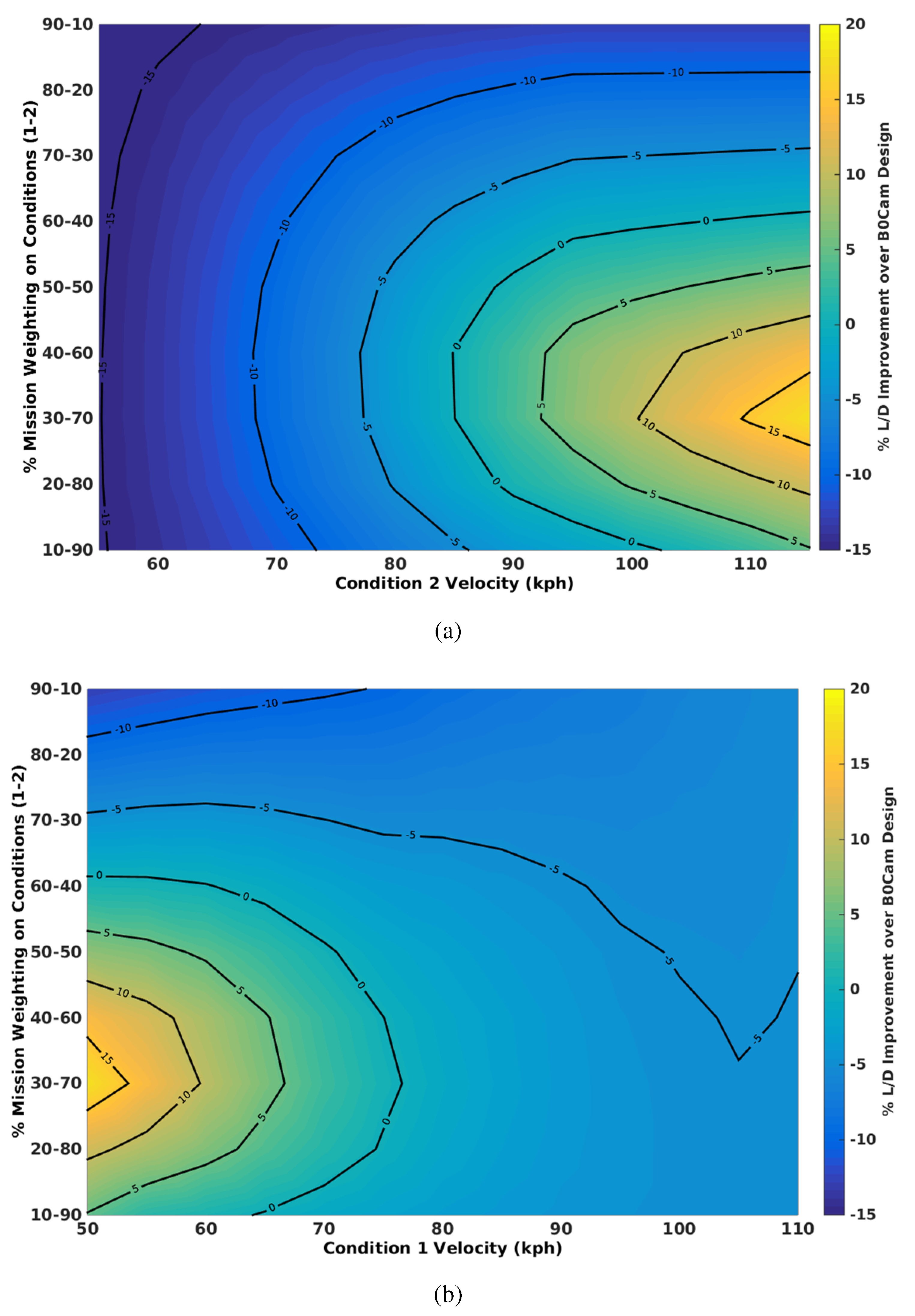
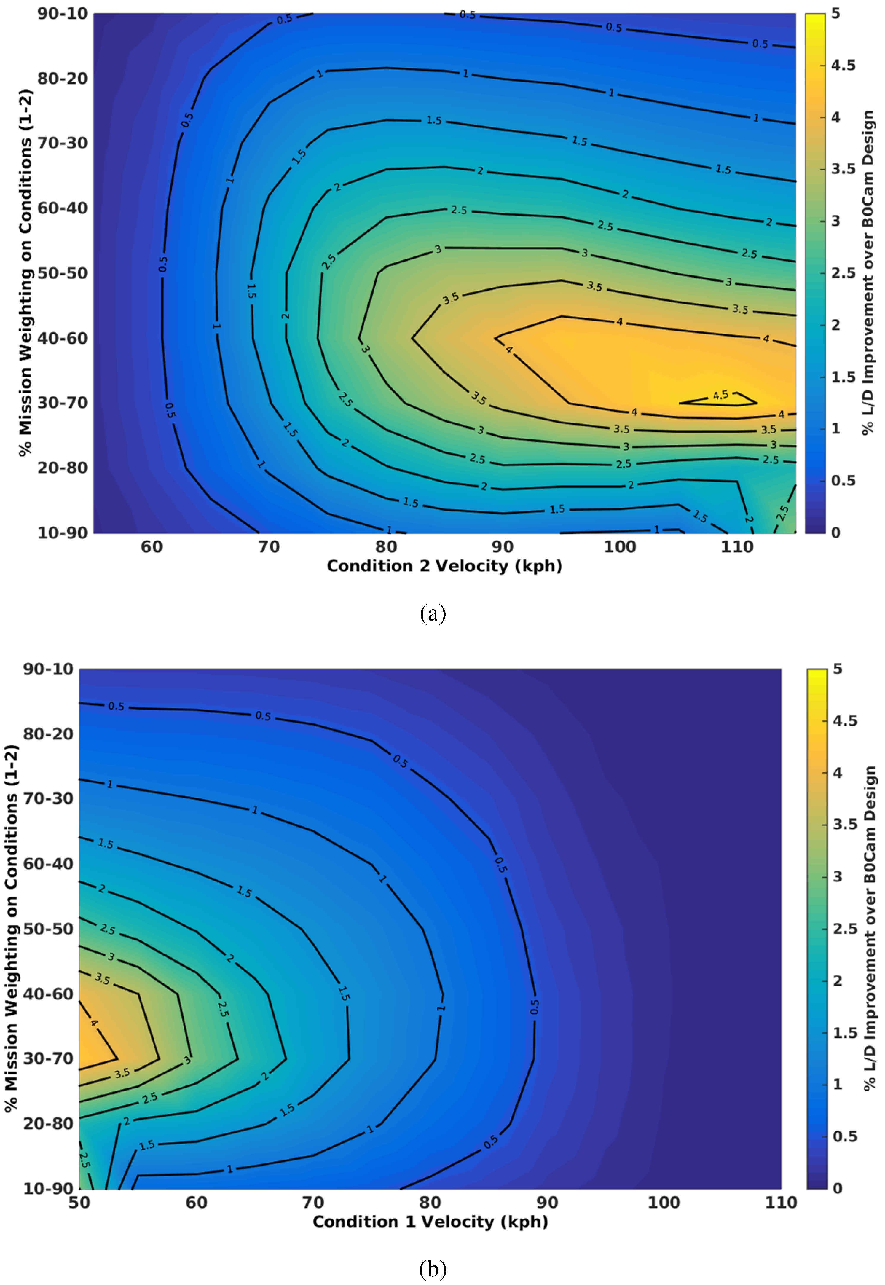
It can be assumed that as this strategy is optimised to allow for an initial camber and a span position for each flight condition, the aerodynamic efficiency will be greater than only allowing for the camber and baseline span to be optimised. Like the span morphing without camber, the optimum mission weighting appears between 30 and 70 and 40%–60%. For other mission weightings, there is a minimum speed range, beyond which the increasing range has little effect on the improvement in aerodynamic efficiency.
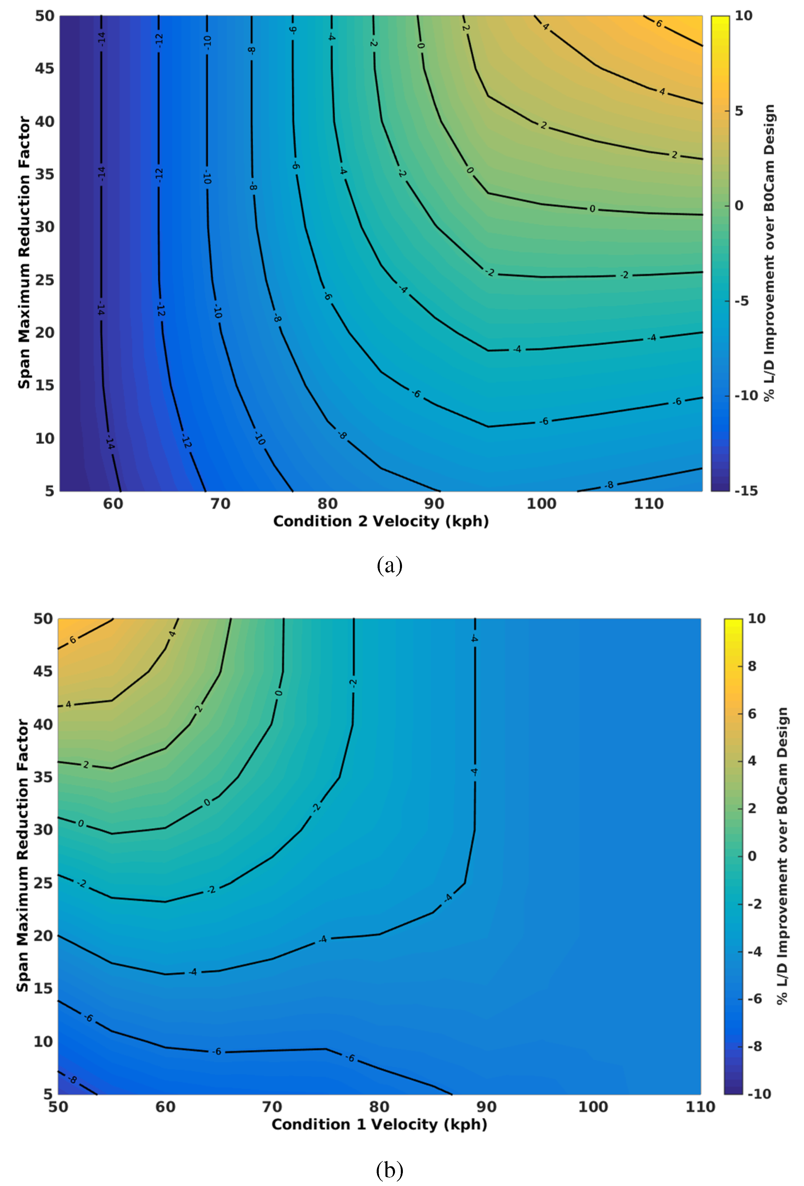
Figure 16 presents the effect of reducing the allowable span reduction factor.
Along with
Figure 15,
Figure 16 would suggest that as the range is increased, the benefits of span morphing would diminish gradually. Similar to
Figure 14, as the maximum allowable reduction is reduced, the speed range of improved aerodynamic efficiency reduces, and maximum improvement also reduces. Furthermore, as the optimum range is approached in
Figure 16a, the rate improvement in aerodynamic efficiency decreases, beyond which a gradual decay in the efficiency is observed.
Figure 15.
Effect of mission weighting on aerodynamic efficiency for optimum span with camber over variable speed ranges normalised to the baseline camber design. (a) Aerodynamic efficiency for low speed fixed at 50 kph; (b) aerodynamic efficiency for high speed fixed at 115 kph.
Figure 15.
Effect of mission weighting on aerodynamic efficiency for optimum span with camber over variable speed ranges normalised to the baseline camber design. (a) Aerodynamic efficiency for low speed fixed at 50 kph; (b) aerodynamic efficiency for high speed fixed at 115 kph.
Figure 16.
Effect of maximum span modification on aerodynamic efficiency for optimum span with camber over variable speed ranges normalised to the baseline camber design. (a) Aerodynamic efficiency for low speed fixed at 50 kph; (b) aerodynamic efficiency for high speed fixed at 115 kph.
Figure 16.
Effect of maximum span modification on aerodynamic efficiency for optimum span with camber over variable speed ranges normalised to the baseline camber design. (a) Aerodynamic efficiency for low speed fixed at 50 kph; (b) aerodynamic efficiency for high speed fixed at 115 kph.
4.2.3. Camber Morphing
Here, the camber morphing results are analysed. Unlike the span morphing, the required camber for all conditions only requires minor modification of the root camber, well within the limits of the camber morphing concept under consideration.
Figure 17 presents the effect of mission weighting on the camber morphing results.
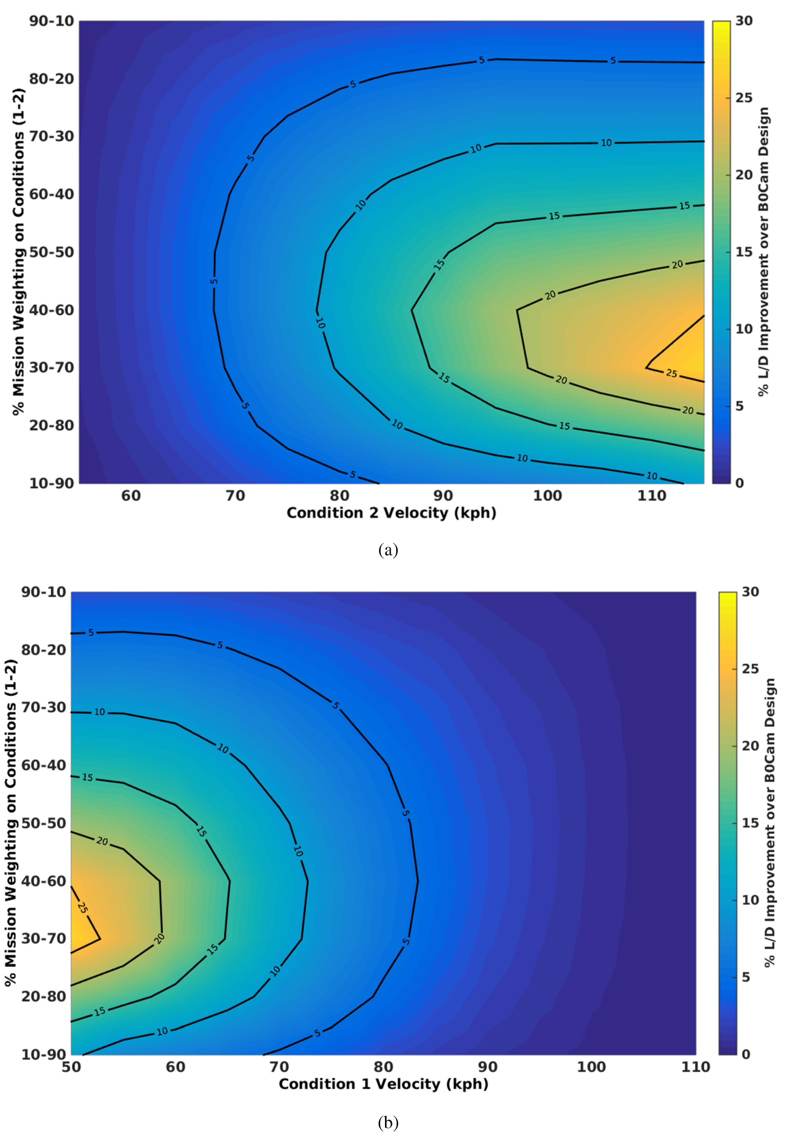
Figure 17.
Effect of mission weighting on aerodynamic efficiency for optimum camber morphing design over variable speed ranges normalised to the baseline camber design. (a) Aerodynamic efficiency for low speed fixed at 50 kph; (b) aerodynamic efficiency for high speed fixed at 115 kph.
Figure 17.
Effect of mission weighting on aerodynamic efficiency for optimum camber morphing design over variable speed ranges normalised to the baseline camber design. (a) Aerodynamic efficiency for low speed fixed at 50 kph; (b) aerodynamic efficiency for high speed fixed at 115 kph.
The results in
Figure 17a show that there is an optimum maximum range for camber morphing in this concept, of between 50 kph and 110 kph, and a mission weighting of between 30%–70% and 40%–60%. Unlike the span results shown in
Figure 13 and
Figure 15, as the range narrows, the optimum mission weighting changes, increasing the importance of the lower speed condition, but also the performance across other weightings does not show a significant decrease as for the higher ranges.
Figure 17b shows similar trends, although there is no maximum range improvement as observed when one condition is fixed at 50 kph. This implies that the camber is more effective at ranges that include a low speed condition compared to a range with two high speed conditions.
In comparison to
Section 4.2.1 and
Section 4.2.2, the maximum gain using camber morphing is approximately 4.5%, where span morphing shows up to 25%. It must, however, be remembered that modifications to the structure for span morphing may require significant topological changes to accommodate a large span extension/retraction. This includes modifying the skin so that the skin no longer carries bending loads, changes to the main load bearing spars to allow for telescoping, which include reducing its second moment of area and the necessity to also carry spanwise axial buckling loads through the spar. These changes are likely to lead to additional mass required for the structure in addition to actuation. The impact of this is likely to reduce any potential benefits in terms of the effect of improved aerodynamic efficiency on the range and endurance (see Equation (
4)). This effect will be investigated in the next section.
4.2.4. Effect of Mass
In this section, the potential benefits in the presence of a mass penalty are investigated. The investigation focuses on span morphing with initial root camber and the camber morphing concept. The span morphing with no camber is removed from the investigation, as the span morphing is limited to a 25% reduction to represent an achievable reduction using the AdAR concept presented in
Section 2. With this limitation, even with no additional mass, the concept cannot improve on the baseline configuration with fixed span and camber, for these mission velocity ranges or weightings.
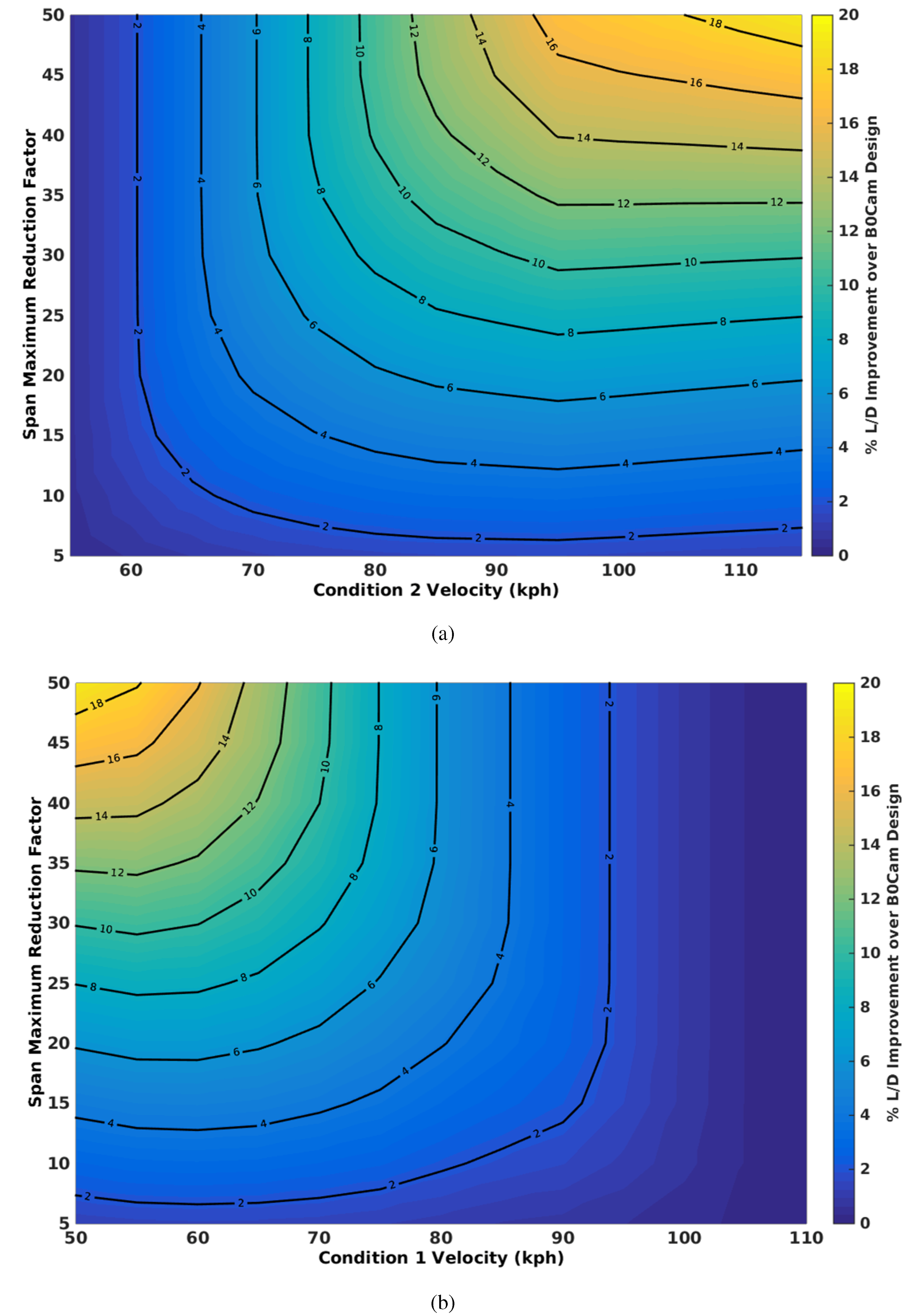
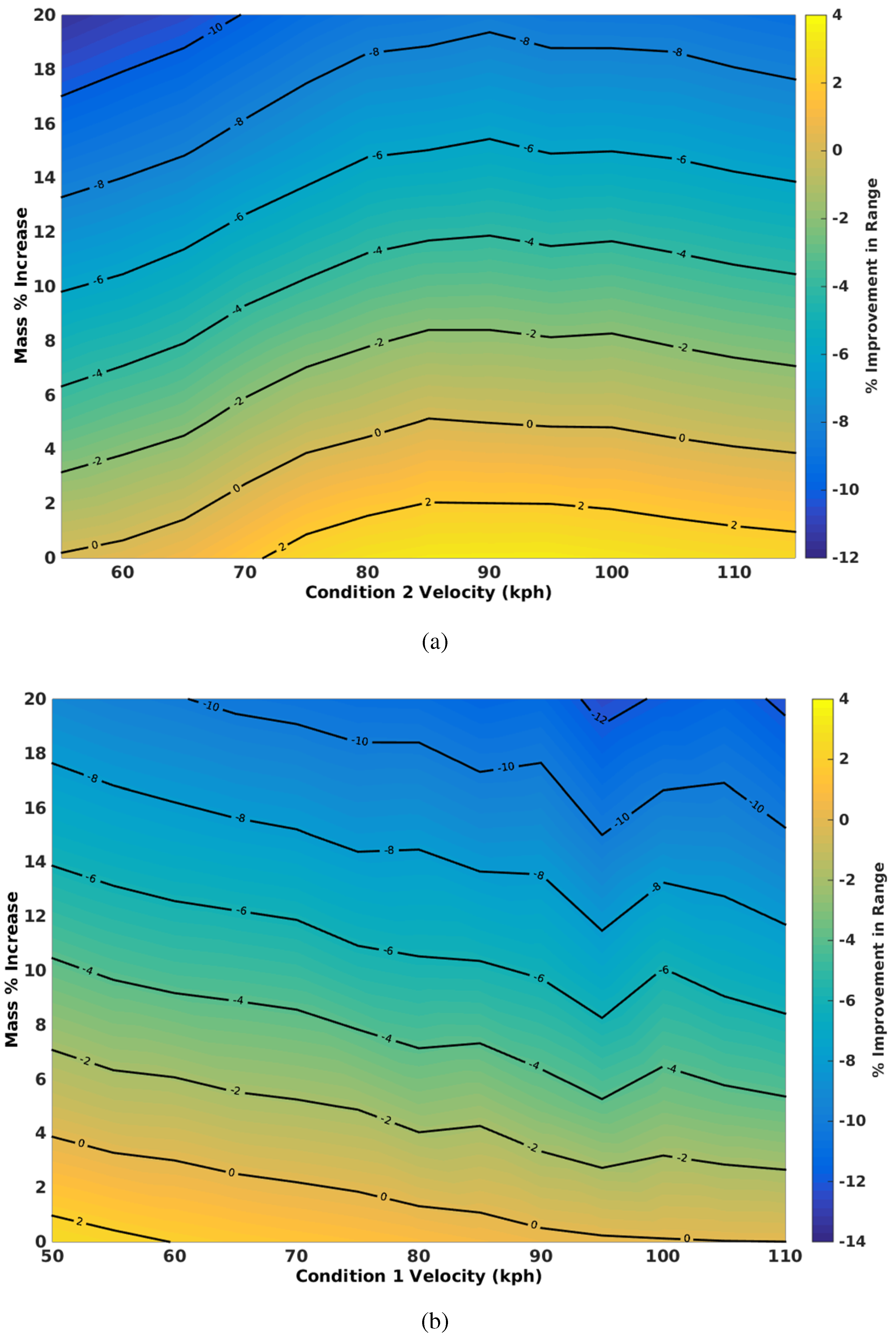
Figure 18 presents the effect of increasing mass on span morphing with fixed root camber. The mission weighting used in this section is 50%–50% from the low to high velocity conditions.
Figure 18a shows that as the additional mass increases, for a given range, the advantage in aerodynamic efficiency diminishes. As the high speed condition is increased, a larger increase in mass can be tolerated, before the advantage of morphing disappears. The maximum observable increase in the range parameter is approximately 8%, with a velocity between 50 and 95 kph. The mass can increase up to 12% (approximately 3 kg) before morphing cannot improve the range, with the high speed increasing to 100 kph. Similarly,
Figure 18b shows that when the high-speed condition is fixed at 115 kph, the optimum low speed condition is approximately 60 kph, with an allowable increase in mass of 12%. Comparing
Figure 18a to
Figure 18b, it is shown that the allowable mass increases at a marginally higher rate when the low-speed condition is fixed and the high speed is varied. The camber morphing aerodynamic efficiency with weight penalty relative to a fixed cambered wing is presented in
Figure 19.
Figure 18.
Effect of mass penalty on aerodynamic efficiency for optimum span with camber over variable speed ranges normalised to the baseline camber design. (a) Aerodynamic efficiency for low speed fixed at 50 kph; (b) aerodynamic efficiency for high speed fixed at 115 kph.
Figure 18.
Effect of mass penalty on aerodynamic efficiency for optimum span with camber over variable speed ranges normalised to the baseline camber design. (a) Aerodynamic efficiency for low speed fixed at 50 kph; (b) aerodynamic efficiency for high speed fixed at 115 kph.
Figure 19.
Effect of mass penalty on aerodynamic efficiency for optimum camber morphing design over variable speed ranges normalised to the baseline camber design. (a) Aerodynamic efficiency for low speed fixed at 50 kph; (b) aerodynamic efficiency for high speed fixed at 115 kph.
Figure 19.
Effect of mass penalty on aerodynamic efficiency for optimum camber morphing design over variable speed ranges normalised to the baseline camber design. (a) Aerodynamic efficiency for low speed fixed at 50 kph; (b) aerodynamic efficiency for high speed fixed at 115 kph.
4.3. Discussion of Results
The flight conditions selected to perform this investigation were a simple low- and high-speed condition, from which various weightings were applied, and the effect on a weighted aerodynamic efficiency or range parameter was used to assess its effect. Results were normalised to a baseline represented by an optimised fixed span and cambered wing. The results first indicated that optimising a fixed camber in the case of span morphing leads to a significant improvement in the viability of this morphing solution over all speed ranges and mission weightings. An uncambered, span morphing design can only improve when the mission weightings are favourable and the flight speed range is large. By limiting a single-stage span morph from 50% down to 25%, the results indicate that even with no weight penalty applied, this solution does not improve the aerodynamic efficiency for any combination of flight speed and mission weighting. The addition of an optimised fixed camber, however, shows that improvements, even with span retraction limited to 25%, can be observed over a large range of mission weightings and speed ranges. Furthermore, in the presence of a weight penalty, for an appropriately-weighted mission and speed range, span morphing with optimised camber can deliver an improvement with a weight penalty of up to 12% and up to an 8% improvement with no added mass. With small speed ranges, the span morphing with camber is very close to the optimum where span and camber can vary over both conditions. The larger the variation in speed, the more the span morphing diminishes over the absolute optimum. However, when compared to the baseline fixed span and camber, only a slow decay in the improvement is seen over these speed ranges. The data indicate that for a maximum span retraction and fixed span, over the speed range, there exists an optimum mission weighting. For this concept, the optimum mission weighting appears to be weighted 30–70 to 40–60 for the breakdown of low to high speed in favour of the high-speed condition. Additionally, the optimum speed range for a maximum span retraction of 25% in this design is 50–90 kph, where increasing the speed range slowly reduces the benefit of span morphing.
Relative to the span morphing results, as was observed in
Figure 17, the absolute improvement of the baseline is not as significant as a 50% span reducing morphing concept. However, the results are far more favourable when compared to a more achievable span reduction of 25%, as observed in
Figure 10 and
Figure 11, and the improvement in the aerodynamic efficiency when the maximum span reduction is reduced in
Figure 12. The maximum benefit observed is approximately 3% improvement in the range parameter, and the optimum range appears to be where the low speed is fixed at 50 kph and the high speed at approximately 90 kph. As the mass penalty is increased, again, the benefits diminish, with the zero contour showing no benefit to morphing using the camber. For the best velocity range, camber morphing can allow up to a 4% increase in mass for morphing to improve the aerodynamic efficiency. Like span morphing with the camber, the decrease in the range parameter at a fixed velocity range is approximately linear with the mass penalty. Comparing
Figure 19a to
Figure 19b, camber morphing appears to be a strategy better employed where the low-speed condition is fixed at 50 kph.
Similar to span morphing with fixed camber, camber morphing with no weight penalty leads to an improvement in aerodynamic efficiency for all mission weightings and all flight speed ranges over a fixed camber and span alternative. The maximum attainable improvement is 4.5% at the optimum speed range and mission weightings. Unlike the span morphing, the optimum speed range and mission weightings are well defined, where the drop in improvement is more rapid when increasing or decreasing the speed or adjusting the mission weightings. For lower speed ranges, the improvement in aerodynamic efficiency is relatively insensitive to mission weighting. As with the span morphing, generally, the improvement in the range parameter is reduced with increasing weight penalty, where at the optimum speed range and mission weighting, a 3% improvement is observed for a 50–50 mission weighting, allowing up to a 4%–5% increase in mass. The data indicate that the variation in camber required for these improvements is between a 1% and 5% tip deflection compared to the root chord length. This is well within the limitations of the FishBAC concept.
It is clear from these results that morphing can provide a strategy to improve the aerodynamic performance of a platform.
Figure 18 and
Figure 19 show that even in the presence of a weight penalty, a morphing platform can deliver an improvement in range through aerodynamic improvements. The challenge is then to build a concept that can achieve this shape modification, with as little added mass as possible. It must also be noted that the planform and cross-sectional modification for the morphing designs allow greater control over the operating angle of incidence and lift. As a result, high lift systems, such as flaps, deployed for other conditions, such as climb and descent for take-off and landing phases, are not required. The basic fixed configuration would, however, require modification to integrate these systems, in order to complete these flight phases.
5. Conclusions and Recommendations
This paper has presented an overview of two wing morphing concepts: a span morphing concept (AdAR) and a camber morphing concept (FishBAC). A mathematical modelling framework was presented to simulate the aerodynamics of these concepts. This model was then used to simulate the performance, to optimise the wing geometry for fixed and morphing wings for a variety of speed ranges, mission weightings, weight penalties and, in the span morphing case, maximum allowable span retraction.
Comparing these two design strategies appears to favour span morphing with fixed camber over a camber morphing concept. However, there are caveats to this argument. Span morphing generally requires modification of primary structural components and, potentially, adjustments to the underlying structural design philosophy/topology. In the case of the AdAR concept, to achieve significant span modification, spars must support all of the bending loads generated by the aerodynamics, systems and material choices that allow ribs to slide, as well as using compliant skins to allow significant extensions, or retractions, leading to an increase in weight for an equivalently stiff structure. Furthermore, actuation loads required to enable significant straining of a compliant skin lead to even greater weight penalties. The camber morphing concept, however, modifies only the trailing edge of a wing, allowing a continuous stiff spar to carry the aerodynamic loads. Although the maximum benefit of camber morphing is 2–3-times less than a 25% span reducing cambered concept, the likely weight penalty induced by using this concept is considerably less. Furthermore, the motion required to achieve the improved aerodynamic efficiency is only approximately a 4% change. For a concept like FishBAC, which can achieve up to a 25% tip deflection, the additional deflection could be utilised at high lift flight conditions, such as take-off and landing, to reduce the required angle of incidence with a fixed wing, where otherwise a high lift system may need to be integrated. The optimum mission weighting is approximately the same as that for a span morphing concept, with greater sensitivity in the speed range as it increases beyond the optimum. The optimum speed range appears slightly narrower than span morphing.
In summary, this analysis shows the effect of mission parameters, such as low- and high-speed conditions, and mission weightings. Maximising the effect of span morphing is dependent on the operational speed range, in addition to the weighting of the mission between low and high speed. The data suggest that for the wing under consideration, the morphing appears to favour heavier weighting on the higher speed condition. Span morphing with camber appears to have the most favourable aerodynamic efficiency improvements for a mission with low- and high-speed phases. However, observing that span morphing may lead to larger weight increases, camber morphing may be a more favourable option. The improvement in span morphing with camber diminishes with increasing flight range, but also the maximum attainable span reduction.


