1. Introduction
The current sustainability goals and green agenda regarding environmental issues call for novel, innovative, effective and economic solutions in the aerospace industry. Most of the current investigative trends are focused on flow control and increases in aerodynamic performance (lift increase, drag decrease or both) that directly affect energy consumption, structural requirements and flight dynamics and control, as well as flight safety and comfort. The advances in materials, actuators, sensors and similar smart technologies have introduced breakthroughs that can provide significant improvements regarding aircraft safety, affordability and sustainability by revisiting the possibility for bio-inspired smooth and continuous shape-changing aerodynamic designs, hence reigniting the interest in morphing aircrafts after more than a century of utilizing conventional designs with hinges and pivots. Two examples of successful projects covering some of these topics are the Clean Sky and Clean Aviation initiatives [
1,
2].
Morphing lifting surfaces, originally found in nature [
3,
4,
5], can greatly advance the development of more efficient aircraft due to their ability to change shape (usually span, chord and curvature) and adapt to diverse flight conditions.
Likewise, morphing airfoils, blades and wings (or wing parts) can also accelerate the expansion of more advanced and efficient unmanned aerial vehicles (UAVs) by improving their performance over a broader range of different operating conditions. This is manifested primarily during the flight mission segments, i.e., cruise vs. climb, or with a varying Reynolds number (
Re) induced by changing speed or altitude (since most of these aircraft are used for surveillance, scientific measurements or deliveries). So far, different bionic (bio-inspired) solutions have been investigated and tested on UAVs [
6,
7,
8]. However, there is still no unique solution, and different options should be investigated further (numerically, experimentally and in flight). On the other hand, the governing constraints are rather universal, and most often imply mechanical simplicity and effectiveness.
Initial passive approaches, including lift increasing devices (such as flaps and slats) or winglets (meant to decrease the negative effects of tip vortices), have been employed on wings and blades for decades and have demonstrated their benefits [
9]. They also proved extremely significant for noise generation and regulation [
10]. More recent research and engineering efforts have turned to active leading and trailing parts capable of changing their shape, as described in [
11]. Such solutions, due to increased complexity, require both aerodynamic and structural, and ultimately, aeroelastic, considerations [
12]. Since their variations mostly refer to airfoil camber changes in the fore and aft segments, their contributions are primarily observed in planar (two-dimensional, 2D) analyses, which are also more suitable for design phases, when optimization might also be employed [
13].
Additional interesting solutions proposing more profound (three-dimensional, 3D) shape changes (including active span and pitch varieties) can also be seen in [
14,
15,
16,
17]. In addition to being used to enhance aerodynamic performance, morphing wings can also be used for other purposes, e.g., to maximize the area being exposed to sunlight, which is extremely important for high-altitude solar-powered aircraft [
18]. Due to the large number of variables, optimization studies are often employed to help in defining the optimal (i.e., the most appropriate) solution. More specific tools, developed particularly for the simplified smooth modeling of morphing micro-UAVs, are presented in [
19].
Going back to wing segments (airfoils), several studies investigate the possibility of producing morphing airfoils using corrugated structures [
20,
21,
22,
23,
24], again applied to a portion of the airfoil. However, the idea in this investigation is somewhat different. We wish to investigate the possibilities of varying the overall airfoil thickness and curvature (very similar to what birds do) in order to achieve better aerodynamic performance (e.g., optimal lift-to-drag ratio) or even design novel control devices. This idea stems from the FishBAC concept, an airfoil morphing structure initially introduced in [
25]. There, the authors investigated possible improvements to NACA 0012’s aerodynamic characteristics by installing a smooth trailing-edge morph. This concept has gained popularity over the past decade, and other authors have also explored it further [
26,
27,
28,
29,
30].
Nowadays, airfoil geometry optimization utilizing a vast variety of optimization and parametrization methods and techniques has become a standard for researchers. While the most popular optimization methods are probably genetic algorithms (GA) and particle swarm optimization (PSO), there are a lot of different approaches to airfoil geometry representation through parametrization. The idea of airfoil geometry parametrization is simple: to achieve satisfiable geometry with as few parameters (most often control points) as possible. For this purpose, several methods exist: Bezier curves, Class Shape Transformation (CST), splines, B splines, non-uniform B Splines (NURBS), PARSEC, etc. All of these have advantages and disadvantages that make them more or less appropriate for different applications.
Given that the goal of this work was to investigate and optimize an airfoil intended for morphing, a different approach was more practical. The airfoil was assumed to resemble a fishbone, similar to the FishBAC concept, consisting of a spine and ribs positioned along its length. Since control of the airfoil geometry can be achieved by adjusting the curvature of the spine, parametrization of the airfoil should include control points for the camber line. Obtaining the optimal shape for the airfoil camber for different flight regimes will significantly simplify the design process in the later phases where the camber’s physical characteristics (thickness, elasticity, etc.) and actuators are selected. To obtain the overall optimal airfoil geometry, its thickness can now be optimized by using the rib lengths as control parameters. Morphing airfoil concept can also play a significant part in noise reduction [
31], but those aspects are not investigated in more detail in the present study.
Hence, in this work, we introduce a novel airfoil generator that enables a change in the complete airfoil shape by investigating different camber shapes and rib lengths positioned along it (highly resembling a fishbone). We propose a state-of-the-art solution that could contribute to improved aerodynamic efficiency (expected improvements reach 20%), and reduced energy/power requirements. It is mechanically simple (we employ three internally positioned sliders) and can be achieved with contemporary materials and production techniques and advanced modeling approaches, thus making it a perfect solution for contemporary UAVs. The long-term desired outcomes stemming from this research study are to connect theory and practice, and to set a solid foundation for future more advanced experimental studies involving actuated and automated structures that can achieve improved performance.
2. Airfoil Design
While the introduced morphing concept can be applied to aircraft of all sizes (from small- to large-scale), manned and unmanned alike, here, we will focus on smaller UAVs and medium Reynolds numbers (ranging from 0.05 × 10⁶ to 0.1 × 10⁶, i.e., from altitudes of 8000 m to 0 m, respectively, for the same velocity and reference length). These flow regimes are generally challenging to analyze due to their high sensitivity to external disturbances, like wind, dirt (such as dust, sand, insects) and turbulence, and a number of accompanying flow phenomena (with transition to turbulence as one of the most widely recognized).
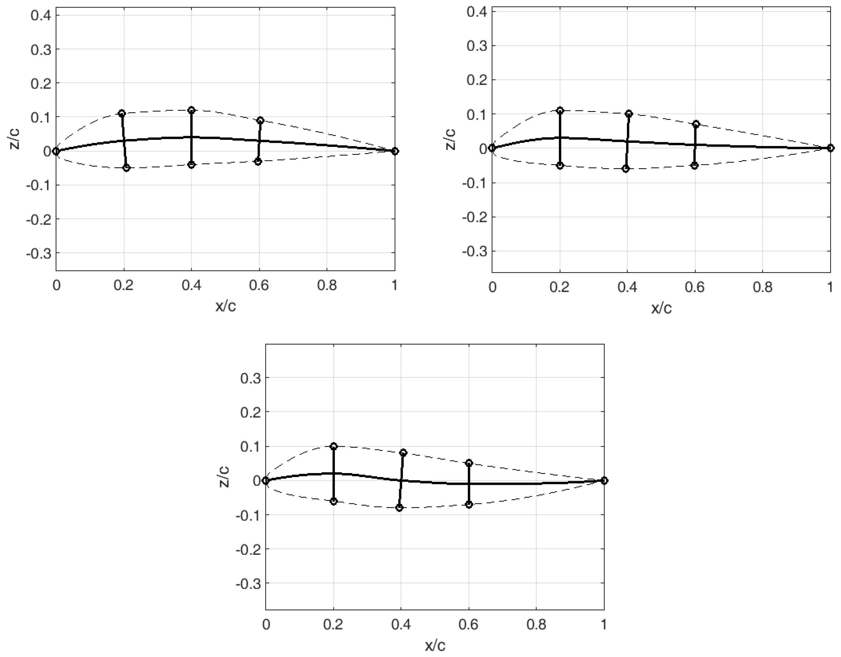
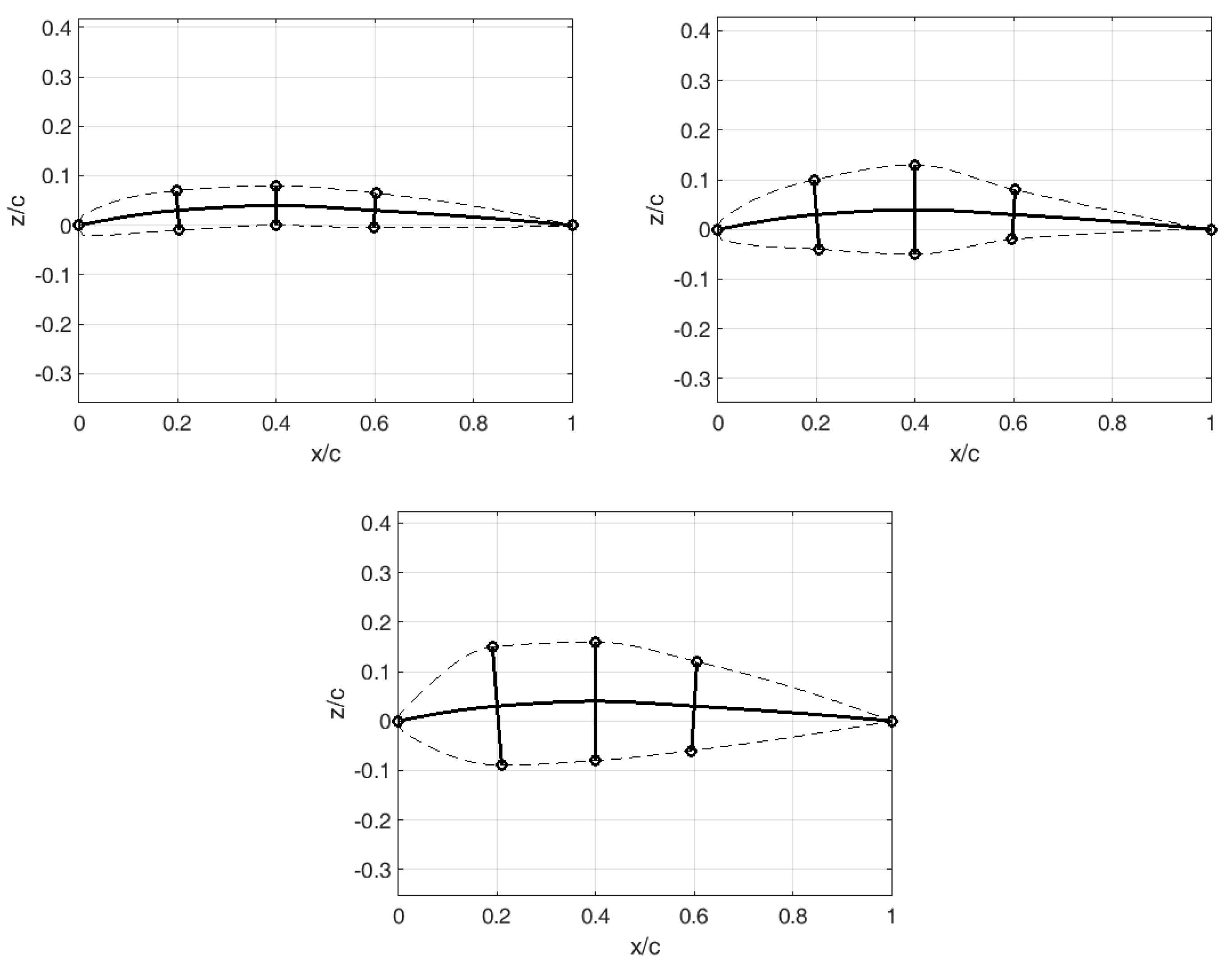
Given that the simplest solution is sought (both geometrically and mechanically), the airfoil is parameterized by just six input parameters, three displacements of spine control points
y1,
y2 and
y3 along the three internal sliders (corresponding to a chord lengths of 0.2c, 0.4c and 0.6c, respectively) and three corresponding relative thicknesses,
rd1,
rd2 and
rd3. In addition to the three invariant axial positions of the sliders, elastic skin, circular leading and sharp trailing edges are also assumed. For fixed thicknesses, a great variety of different airfoil shapes can be achieved by simple translation of the spine control points (
Figure 1). Likewise, for a fixed spine, a practically infinite number of airfoils (spanning from thin to thick) can be generated/designed (
Figure 2).
The airfoil camber is a cubic spline comprising five points (the leading point, three control points with a fixed x-coordinate and a varying y-coordinate, and the trailing point). The ribs always remain perpendicular to the spine, whereas their length can vary (therefore affecting the airfoil thickness). After defining the spine and ribs, it is possible to construct the upper and lower airfoil surfaces. Again, they are cubic splines that take the shape of the circular arc in the vicinity of the leading edge, thus ensuring continuity of the zeroth and first degree between the airfoil pressure and suction sides.
3. Computation and Optimization
Since the proposed method fully defines different airfoil shapes (that may correspond to the cross-sections of wings, empennages, propeller blades or any other lifting surfaces that may be found in UAVs), it was chosen to perform 2D flow analyses, which are also more suitable for the subsequent optimization studies due to the smaller computational cost.
The aerodynamic characteristics of the generated airfoils were estimated by XFOIL, a panel method based on the corrected potential flow theory proposed in [
32], for angles-of-attack (AoAs, α) ranging from −5° to 20°, a low Mach number (compressibility effects are not considered since UAVs fly at moderate speeds) and relatively low
Re = 0.1 × 10
6 (where decreased aerodynamic performance should be expected).
The extents of the design space are provided in
Table 1. All three spine control points may slide equally and symmetrically in both directions, negative and positive. On the other hand, higher thicknesses are allowed in the two fore-invariant axial positions in comparison to the third, most aft section (thus preserving the geometric notions of streamlined bodies). In this way, airfoils with maximal relative thickness spanning from approximately 6% to 25% are considered.
Based on the result for each considered airfoil, it is possible to estimate the changes in the lift , drag and pitching moment coefficients with the angle-of-attack and derive the optimal lift , lift-to-drag ratio , climbing factor , etc.
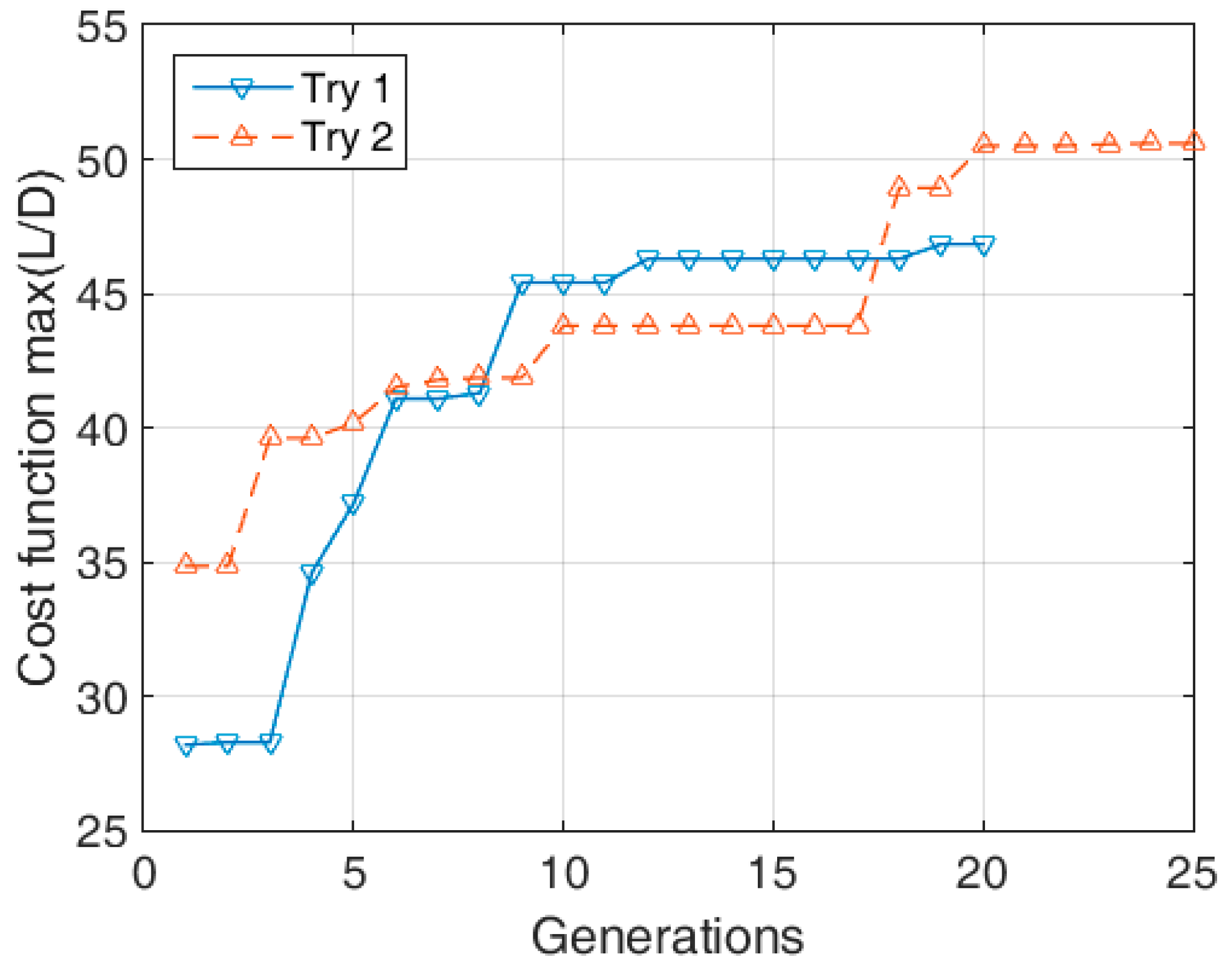
Optimization cycles are performed by a single-objective genetic algorithm (GA) [
33] that mimics/imitates the process of natural selection. It is widely employed due to its robustness, ease of implementation, fast convergence and applicability to different numbers of input parameters (both continuous and discrete). In this case, the population usually comprised 200 individuals that were compared and matched/mated for at least 25 generations until we achieved convergence of the output parameter (i.e., cost function defined as
and
for each case, respectively).
To ensure valid, optimal results, the optimization process was repeated several times for different combinations of parameters (population size, number of generations, etc.).
Figure 3 illustrates two different conducted optimization procedures. Some fundamental characteristics of genetic algorithms, such as fast convergence, are immediately obvious. Within the first ten generations, a nearly optimal solution is found, whereas the following generations are for fine-tuning. Naturally, the optimization course highly depends on the number of inputs, as well as the physical process that is being investigated.
4. Results and Discussion
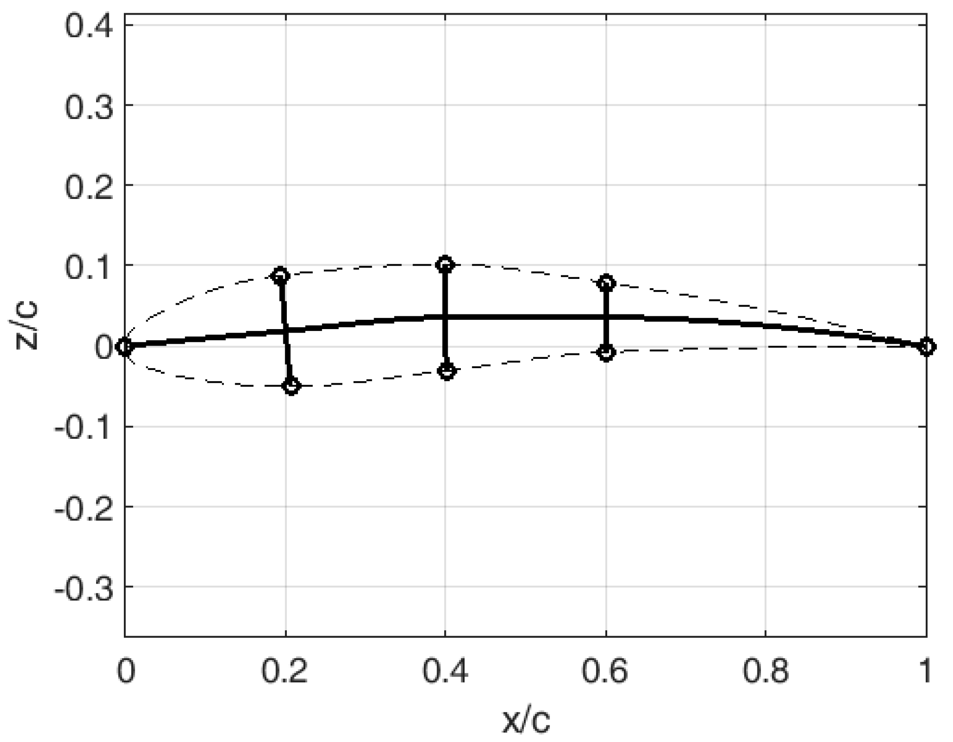
The optimal result designated by the design variables presented in
Table 2 is obtained for the cost function corresponding to the maximal lift-to-drag ratio, and it is illustrated in
Figure 4.
The result is a slightly curved airfoil with 13% maximal relative thickness, with the position of maximal curvature approximately in the middle of the chord.
The morphing capabilities of the identified optimum have some additional benefits. That is to say that for the defined thickness distribution (which will not further change), but for the varying spine, it is possible to achieve improved performance in other flight regimes, e.g., at different Re values (e.g., at 0.05 × 10⁶) or during the climb.
4.1. Validation of the Optimal Design by CFD Approach
However, prior to investigating the different operating conditions, it was first necessary to validate the performed simplified flow analyses. For that purpose, a more advanced computational approach was employed. The governing flow equations were solved by the finite volume method using the commercial suite ANSYS FLUENT [
34].
A classical, well-proven modeling approach was adopted [
13]. The geometric model was 2D, extending 12.5 chord lengths around the airfoil. C-H structural meshing was employed, with fine cells near the walls resulting in a dimensionless wall distance predominantly below 2 along the airfoil,
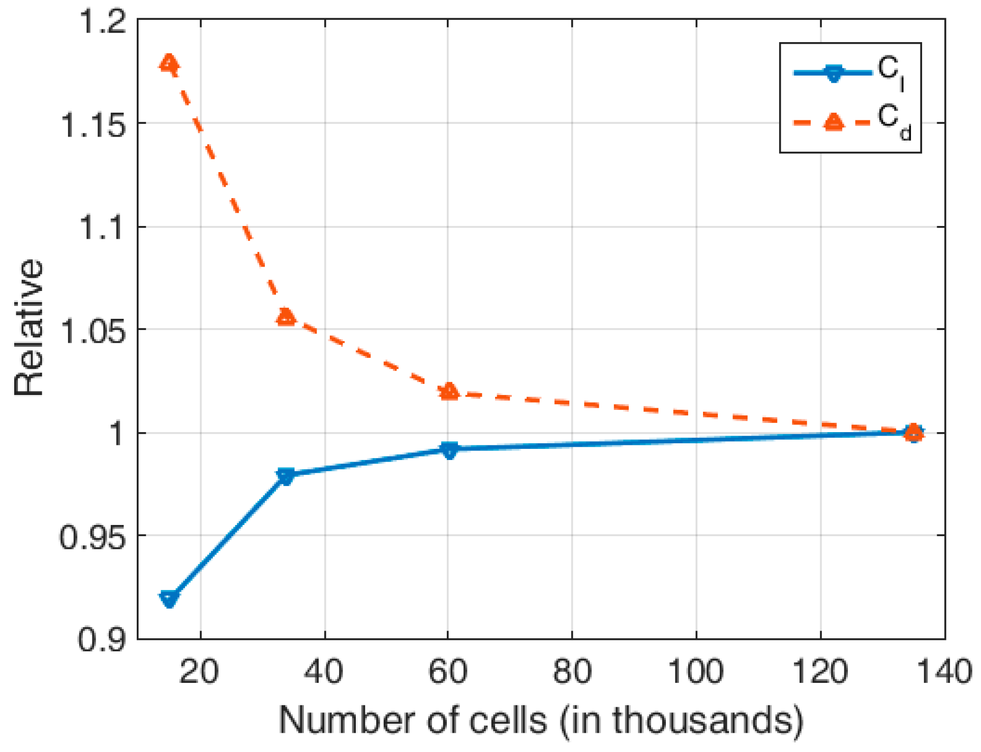
y+ < 2, which was sufficiently fine for resolving the flow adjacent to the wall surfaces. To ensure that the aerodynamic characteristics were not significantly influenced by the computational mesh, a grid convergence study was performed. The lift and drag coefficients obtained on four different meshes, obtained by increasing the number of divisions along the boundaries, are compared in
Figure 5. The mesh, with relative errors lower than 2%, totaling over 60,000 cells, is found to be satisfactory for the current research purposes.
The flow was considered 2D, stationary, incompressible, and viscous. The Reynolds-averaged Navier–Stokes (RANS) equations were closed by k-ω SST or transition SST (more suitable for lower Re) turbulence models. Standard air properties were assumed.
Velocity was defined along the inlet boundaries (for Re = , c = 1 m, Vo = 1.46 m/s), with zero gauge pressure along the outlet, and no-slip walls were assumed.
A pressure-based solver was employed (with a SIMPLEC pressure–velocity coupling scheme), and all discretization schemes were of the second order. The lift and drag coefficients were monitored, and computations are performed until they reached their convergence, usually for a few thousands iterations (in most cases, 2000 for k-ω SST, and up-to 4000 for the transition SST turbulence model, respectively) depending on the AoA.
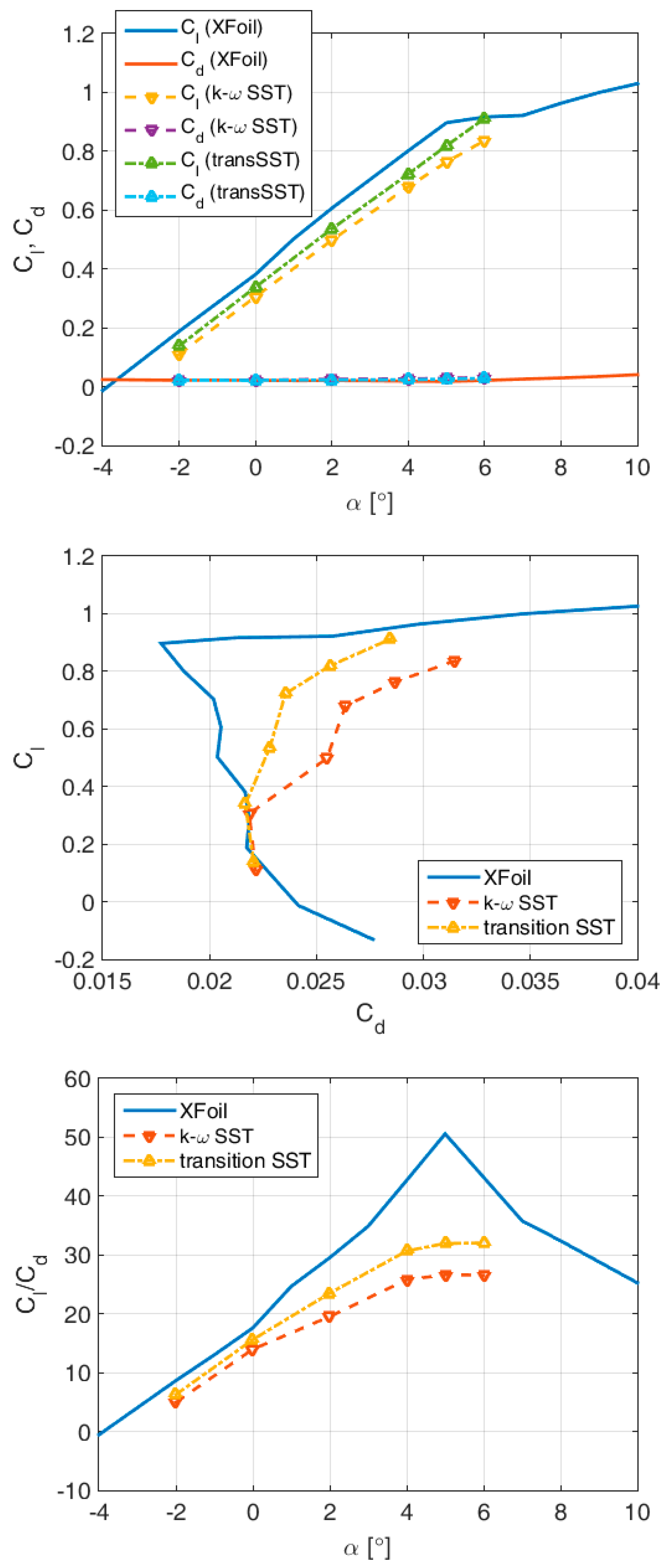
Comparison of the computed aerodynamic characteristics using different numerical approaches, XFOIL vs. ANSYS FLUENT, is illustrated in
Figure 6. The higher values of lift-to-drag ratio obtained by XFOIL seem to be mostly induced by the differences in lift coefficient, i.e., zero-lift angle-of-attack (whereas the lift gradient is nicely captured). Still, the overall trend is well represented, and the optimization may be considered satisfactory. It can be observed that the transition SST model provides more optimistic values (than the fully turbulent
k-ω SST) because of its inherent ability to resolve partly laminar flow along the fore part of the airfoil contour.
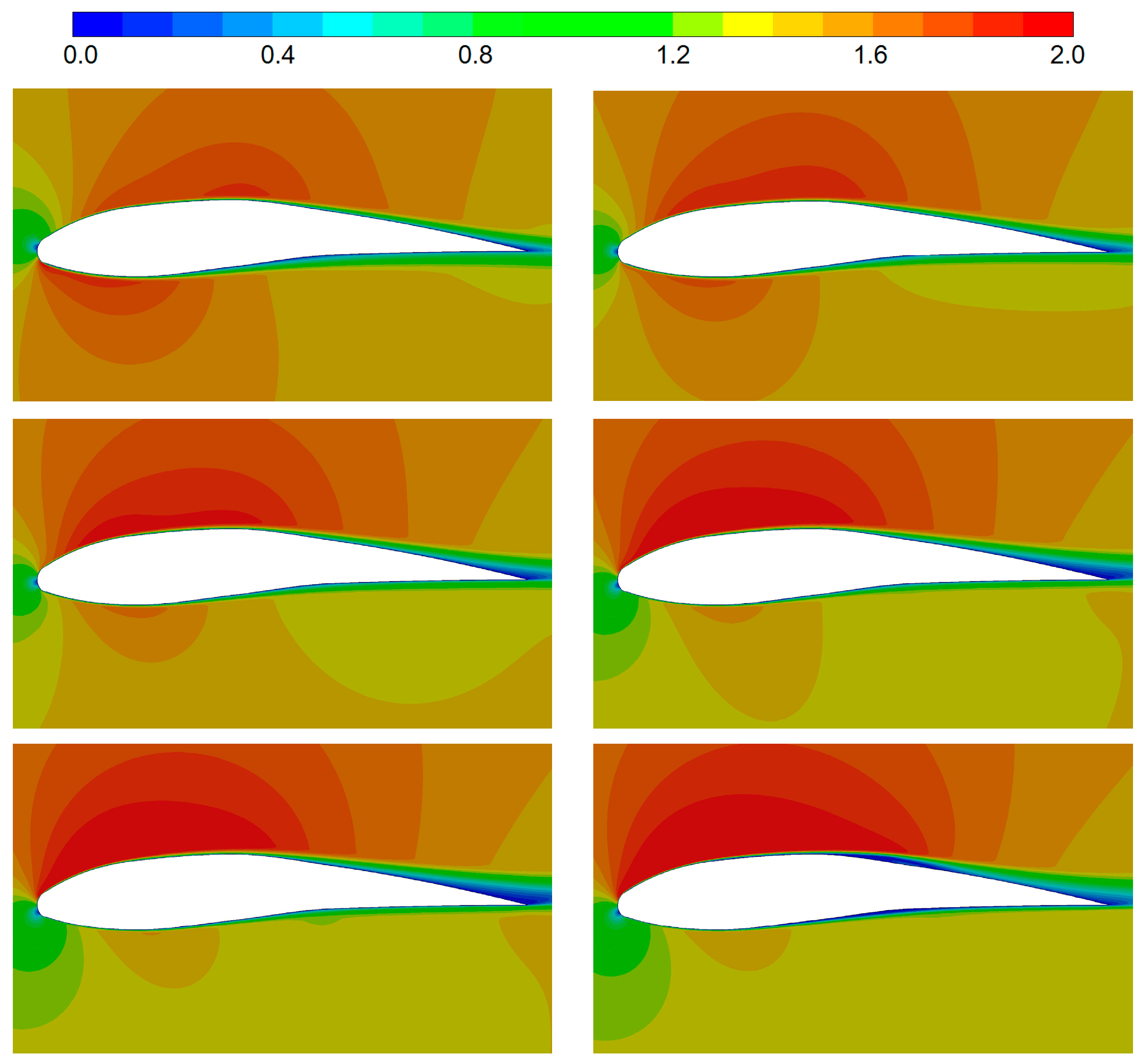
A few flow visualizations (by
k-ω SST) are illustrated in
Figure 7. With varying AoA, the first stagnation point moves along the circular leading edge. Acceleration of the flow along the suction side is apparent, as is slight acceleration on the pressure side (resulting from the initially negative curvature/spine gradient). A rather narrow wake sheds from the trailing edge at all considered AoAs, which is very satisfactory.
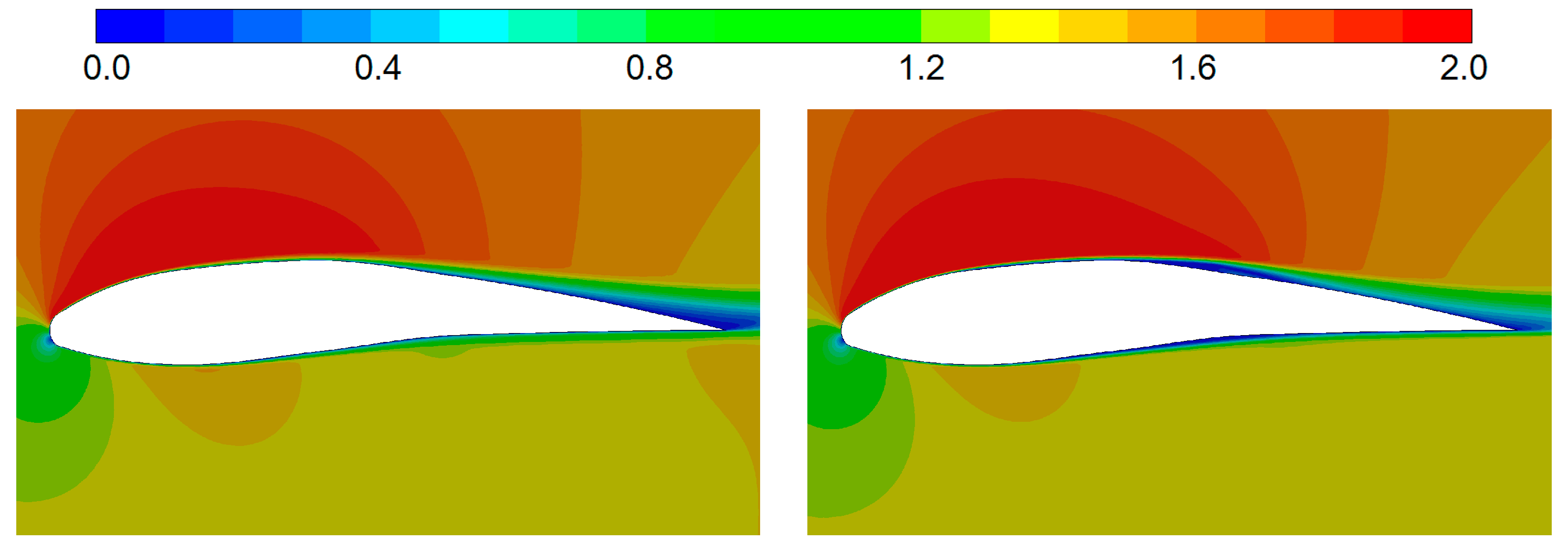
The differences provided by the two turbulence models are illustrated in
Figure 8. The transition
SST model resolves two laminar separation bubbles (LSBs) appearing on both the pressure and suction sides. It can be noted that at a 5° angle-of-attack, the flow remains laminar along the complete first half of the airfoil (and even more), which is very satisfactory, and results in reduced drag and increased lift.
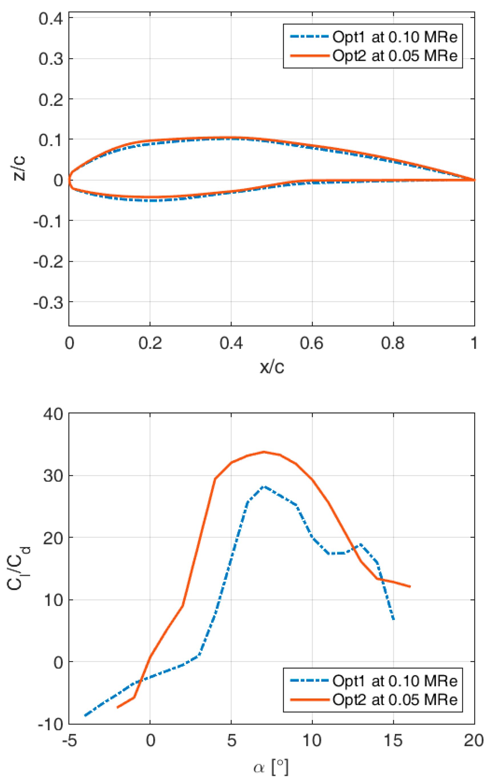
4.2. Optimal Shape at Re = 0.05 × 10⁶
The basic idea of the proposed morphing airfoil is to be able to change its shape in flight to better adapt to the current operating conditions. So, even if the thickness (rib lengths) cannot be changed, the curvature can (by varying the y-coordinates of the control points within the slider boundaries), and thus, better aerodynamic performance can be achieved.
For example, the previously obtained optimum might not be the best solution for a lower Re (at higher altitudes or lower speeds). The optimization process was repeated for the smaller number of inputs (only , and ) and Re = 0.05 × 10⁶.
The results are compared in
Figure 9 and
Table 3. It is obvious that by slightly changing the spinal chord (camber) (i.e., by slightly increasing the curvature in the fore part of the airfoil), significant improvement in the lift-to-drag ratio can be expected (in both value (nearly 20%) and trend, since the near-optimal region appears considerably expanded). Also, a decrease in aerodynamic performance with decreasing
Re can be noted, even in the simple analyses performed by XFOIL.
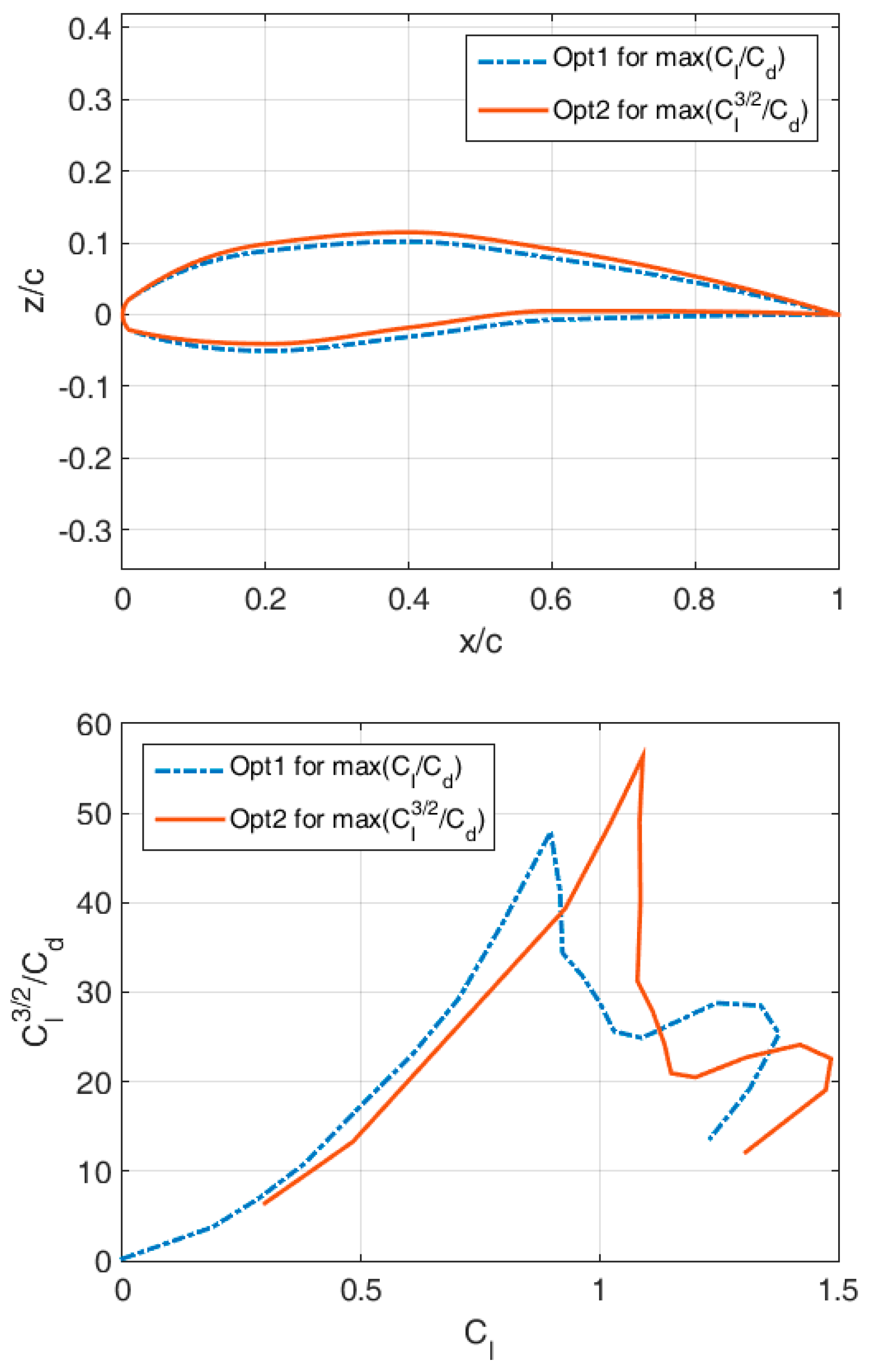
4.3. Optimal Shape during Climbing (Cost Function )
On the other hand, during flight, UAV might need to climb to a higher altitude as efficiently as possible. Thus, the optimization process with the smaller number of inputs (defining just the camber) can be repeated, but for a different cost function max .
It is shown that better performance during climbing can be achieved through an additional curvature increase.
Similarly to the previous case, the relative increase in the climbing factor approaches 20%.
4.4. Validation of the Physical Feasibility of the Concept for Re = 0.05 × 10⁶
4.4.1. Structural Design and Analysis
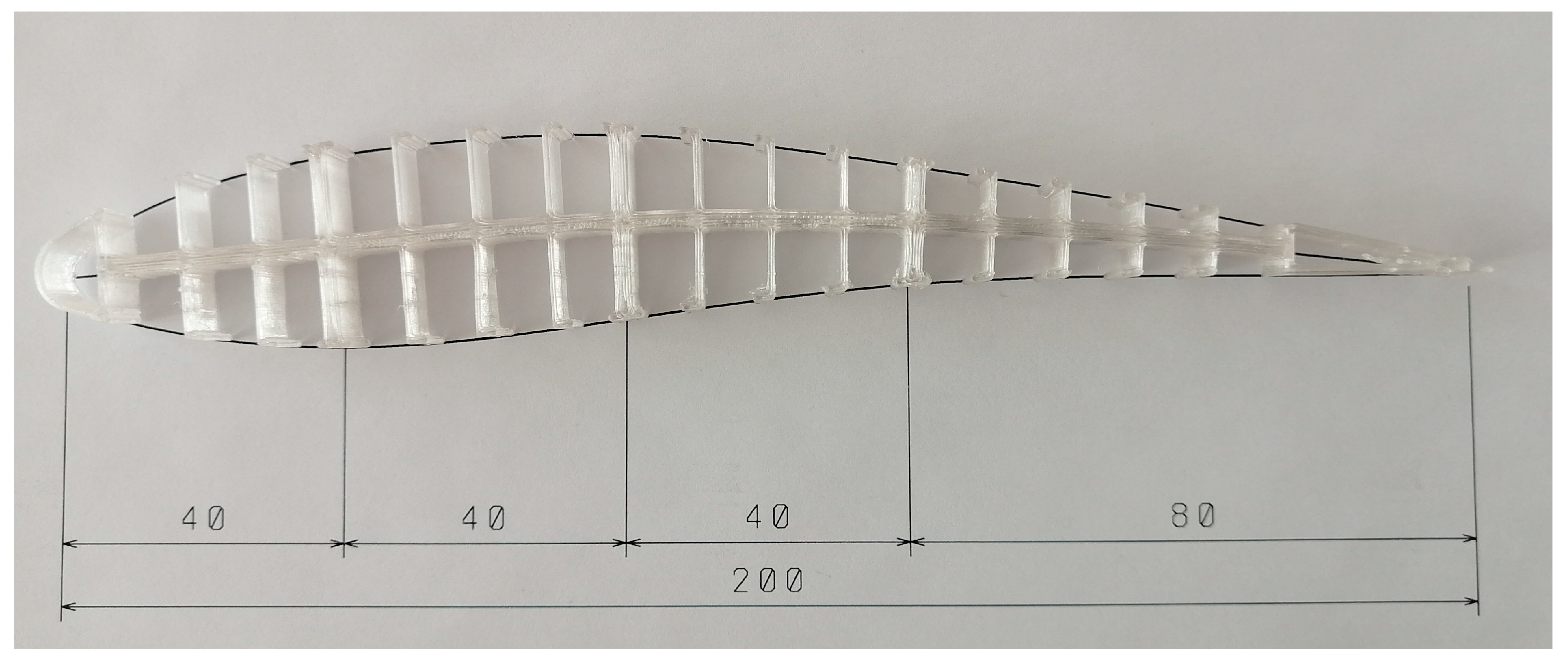
In order to verify the physical feasibility of the designed airfoils, the airfoils optimized for and at Re = 0.05 × 10⁶ were further analyzed. For this purpose, a simplified finite element model discretized with 1D beam elements was created.
At this point in the research, the airfoil skin was ignored since it was assumed to be a non-load-carrying, highly elastic element. The material properties chosen were those of PETG, while the rod properties (width and height of the spline and ribs) were chosen in such a way as to make them easier to print on a FDM printer with a 0.4 mm nozzle and a print height of 0.2 mm. For the same reason the length of the airfoil was chosen to be 200 mm.
The airfoil geometry was parameterized, and deflections in the y direction of the spline control points corresponding to the difference between both airfoils were imposed in the structural analysis. This was used to ensure that the airfoil geometry could be obtained with the defined width and height of the spline and ribs without material failure.
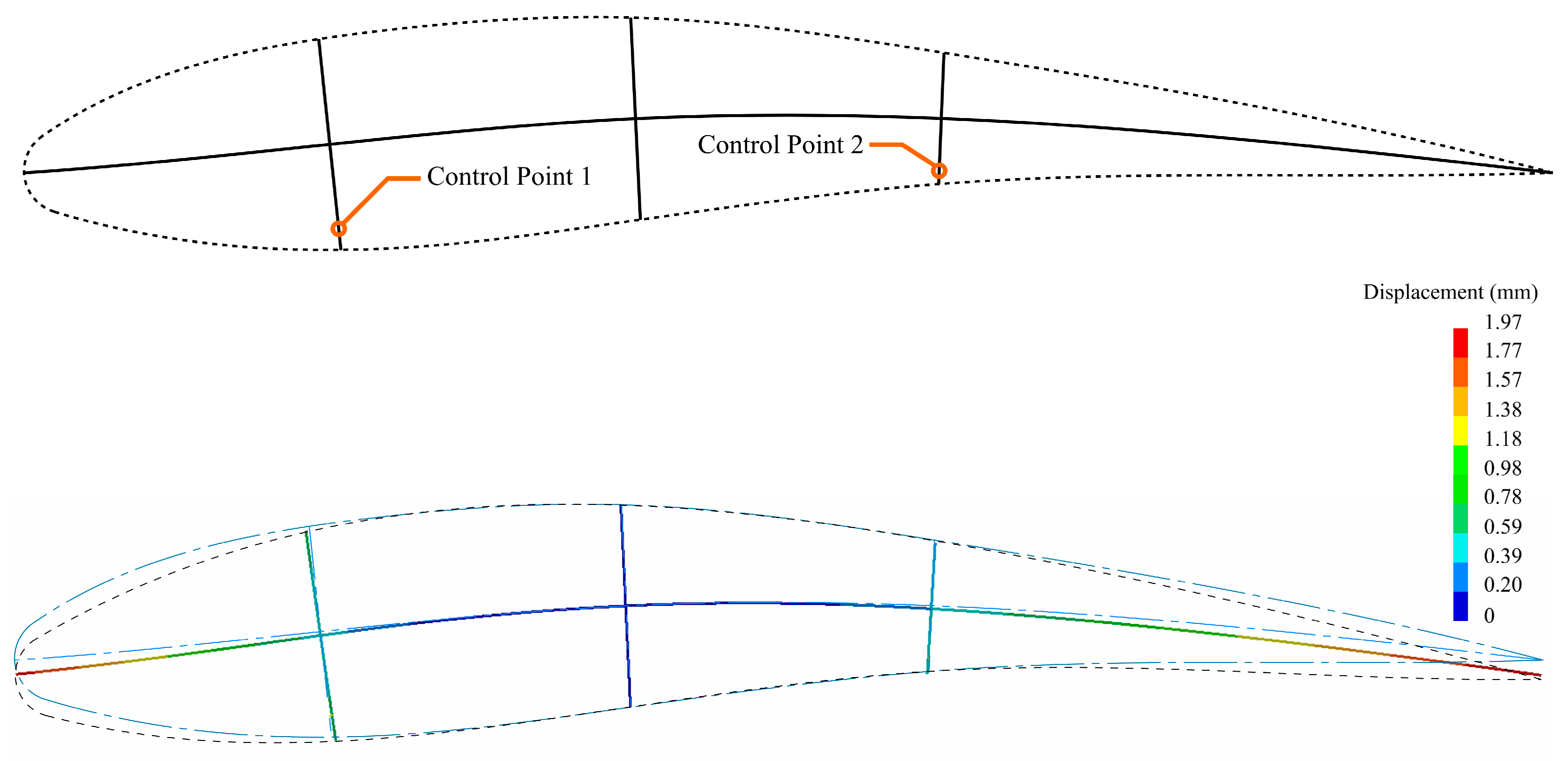
Since the used spline control points were not considered suitable for control purposes, other points on the model were selected on which a force or imposed displacement could be more easily applied. During the static structural analysis, it was noticed that the middle rib (0.4 c) experiences almost pure translation with extremely small rotation, so the control points were set to be on the first and third rib (0.2 c and 0.6 c, respectively, shown in
Figure 11). Initially, the displacement vectors at these points obtained from the first analysis were used as an imposed load, after which the reaction forces in the control points were obtained. These values were then used as a starting point for matching the deformed airfoil with the desired one (optimized for climbing). Displacement sensors were set on the
y0,
y1,
y2,
y3,
y4 and top points of the ribs, and the minimum quadratic norm distance was set as the goal. It was shown that a reasonable match can be obtained with only two control points, with a slight discrepancy in the trailing edge of the geometry, which is to be expected since it was not constrained and the bending force is somewhat far from it. Better concurrence could be achieved by selecting a control point closer to the trailing edge; however, this was not done, since it provides the opportunity to implement a morphing control surface by introducing additional control of the trailing edge in the future. The deformed model is shown in
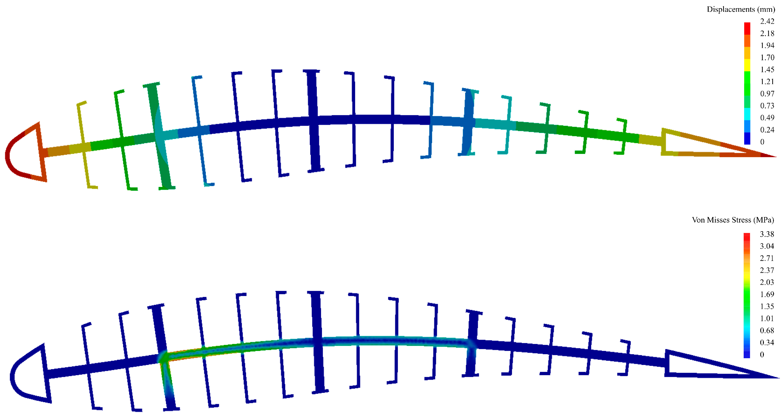
Figure 11.
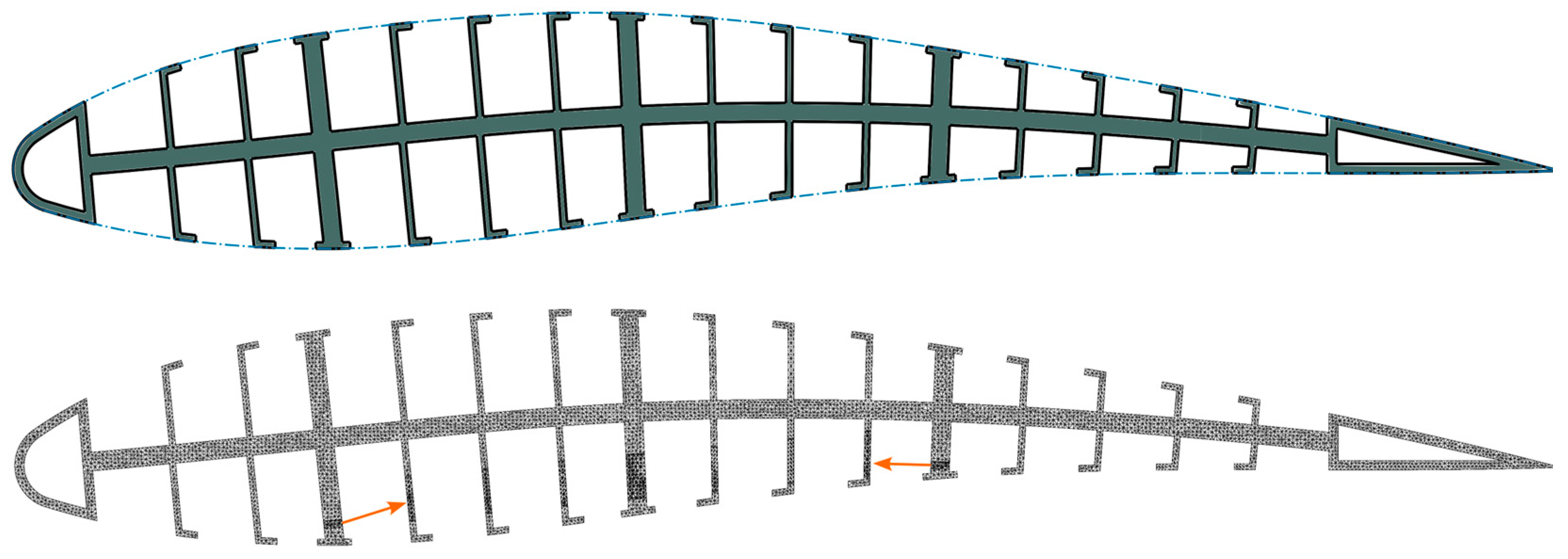
A three-dimensional model of the entire airfoil structure was then designed according to the shape of the
airfoil (
Figure 12). Wireframes of the mesh and the applied forces (orange arrows) are shown as well in the figure.
The 3D structural analysis showed good agreement with the simplified model, with the maximum discrepancy in the calculated deformations being less than 3 percent. The maximum Von Misses stress was shown to be on the lower side of the spline (
Figure 13), with a value of 3.38 MPa, which is considerably less than the maximum yield strength of the material (given as approx. 30 MPa in the XY printing direction and 13 MPa in the Z printing direction by the manufacturer).
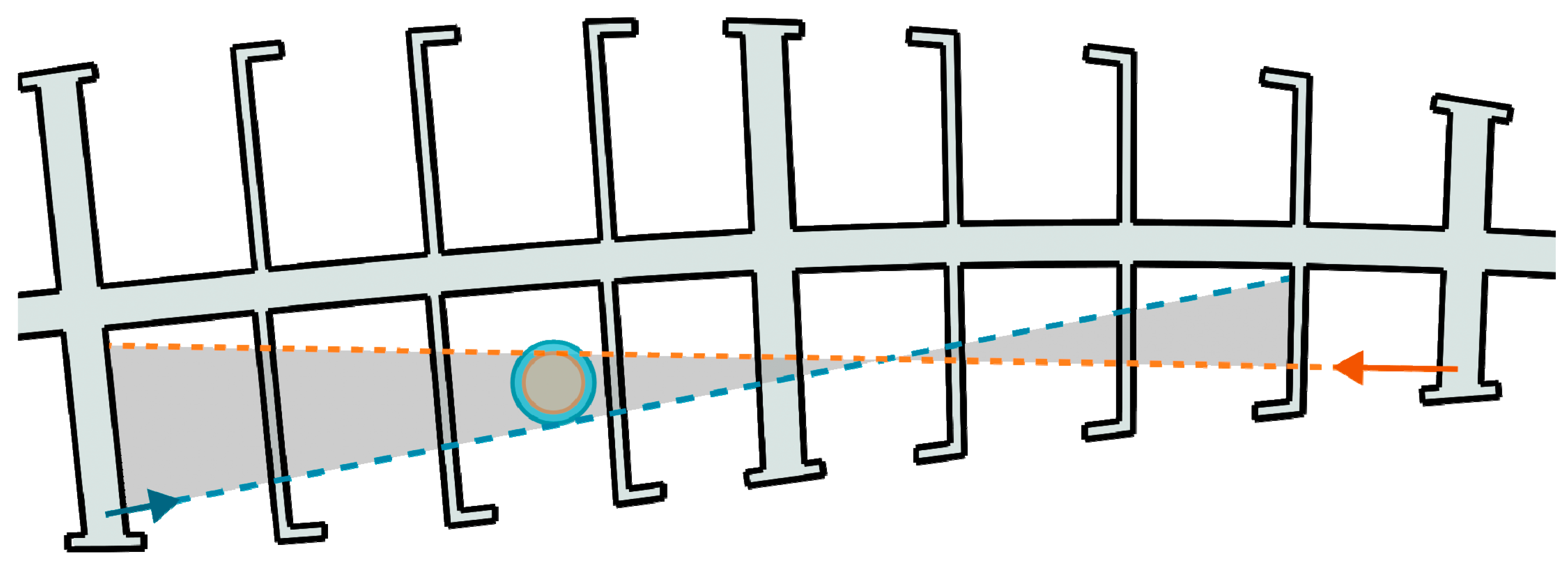
Further analysis of the force vectors shows that there is a point on the inside of the airfoil where the two forces can be obtained by using the same rotation and torque, provided that there are different levers or gear ratios, meaning only one actuator can be used for the change in the airfoil geometry. This is illustrated in
Figure 14.
4.4.2. Manufacturing
The model geometry was 3D-printed on an FDM 3D printer with a clear PETG filament with a nozzle and bed temperatures of 240 deg. C and 80 deg. C, respectively. The entire model was printed with walls requiring no infill. The printing height was set to 0.2 mm and the printing speed 60 mm/s, with a 50% speed reduction for the external perimeters. A photo of the 3D-printed model on top of a printed draft with a 1/1 scale is shown in
Figure 15. To check the accuracy of the dimensions of the 3D-printed part, hand measurements with a caliper were also performed. The maximum deviation of the measured values and the 3D model was less than 2%, with the maximum difference being under 2 mm (for the total length, since a sharp trailing edge could not be printed with a 0.4 mm nozzle).
4.4.3. Experimental Study
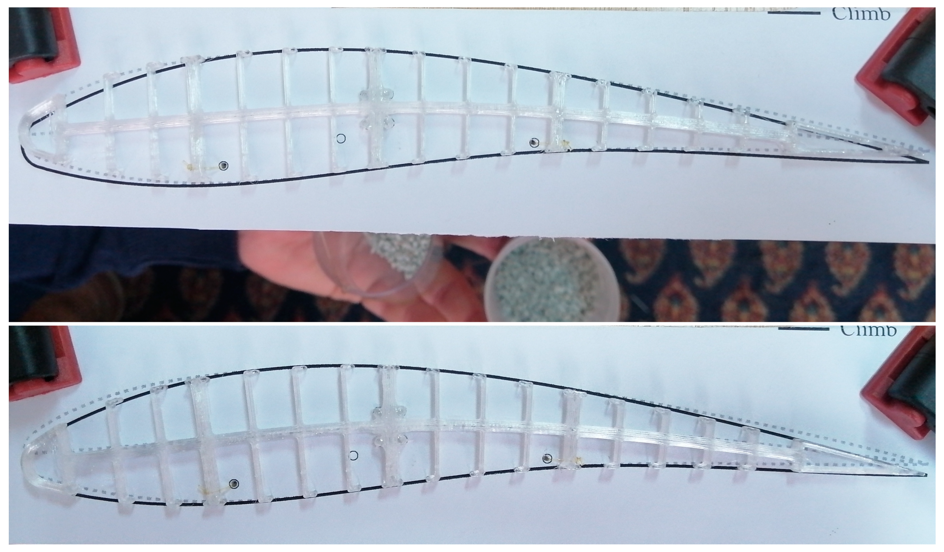
In order to investigate the behavior of the real model, a simple experiment was devised. Initially, two approaches were considered, one with a small servo actuator and another utilizing small weights for the introduction of force. The first option was cast aside since the model was quite small, and although there was enough space for the servo actuator, it was deemed harder to implement, but it will be tried in the future due to the practical advantages it provides. For the second approach, the values of the forces could be represented by using weights, while for the control of the vector directions, an experimental test stand was designed and 3D-printed (shown in
Figure 16). The correct positioning of the model was ensured via four wedges, and the force (represented by cups filled with sand) was introduced through a thin nylon line going through the small holes on the stand, positioned such that the directions of the forces corresponded to the ones used in the numerical analysis. For measurement of the weight, a precise scale was used.
To observe the deflections, a reference geometry was printed on paper and positioned on the test stand (for both deformed and undeformed cases). The deflections of the leading and trailing edges were measured with a caliper and compared to the numerically obtained ones. A difference of ~7.8% between the measured and calculated deflection of the trailing edge was observed. After unloading, the airfoil returned to its original shape. The experiment was repeated several times in order to check for repeatability.
5. Conclusions
This work introduces and inspects the possible benefits of a simple but novel morphing airfoil design where smooth, continuous changes in the lower and upper airfoil surface and satisfactory aerodynamic performance are ensured. The proposed concept allows the generation of a great variety of airfoils considerably differing in their camber and thickness, and is particularly applicable to UAV components (including wings, tails and blades) that must reliably operate in various working conditions. Improved performance of the optimized airfoil configurations is achieved, even at lower Re, which is demonstrated by performing flow computations using two methods differing in their complexity and starting assumptions. Relative benefits of aerodynamic performance nearing a 20% increase were observed for both the lift-to-drag ratio and climbing factor.
The feasibility of the method for obtaining practical morphing airfoils was shown, as well, through the design and analysis of a fishbone airfoil. It was shown that a change between the generated optimal airfoil geometries for cruising and climbing can be achieved with as little as two control points on which forces can be introduced by a single actuator. By changing the height of the fishbone, its rigidity, and hence, the required forces, can be set as desired while ensuring adequate deformation at the same time. In the present study, it was demonstrated that even simple 3D-printed structures can be adequately morphed within the elastic limit of the material. Even with this simplified experimental method, the difference between the desired and actual behavior was less than 10%.
This work provides a good starting point for further investigations. A fast and simple coupled aero-structural optimization model which would include load carrying elements can be created in the future. The proposed optimization algorithm can relatively easily be further extended for the optimization of the entire wing and other three-dimensional aerodynamic models. Furthermore, the airfoil obtained by this model can be used as an initial geometry that can be further improved by utilizing fluid–structure interaction and topological optimization for better control of the elasticity and mass reduction.


