Article

Numerical Simulation of Heat Pipe Thermal Performance for Aerospace Cooling System Applications

1
Italian Aerospace Research Centre (CIRA), 81043 Capua, Italy
2
Mechanical and Aerospace Engineering Department, Politecnico di Torino, 10129 Turin, Italy
*
Author to whom correspondence should be addressed.
Aerospace 2024, 11(1), 85; https://doi.org/10.3390/aerospace11010085
Submission received: 14 December 2023 / Revised: 12 January 2024 / Accepted: 15 January 2024 / Published: 17 January 2024
(This article belongs to the Special Issue Heat Transfer and Cooling Systems for Aerospace Equipment)

Abstract

:
The design of integrated and highly efficient solutions for thermal management is a key capability for different aerospace products, ranging from civil aircraft using hydrogen on board to miniaturized satellites. In particular, this paper discloses a novel numerical tool for the design and thermal performance assessment of heat pipes. To achieve this goal, a numerical Ansys Parametric Design Language code is set up to verify the effective subtractive heat flux guaranteed by the selected heat pipe arrangement. The methodology and related tool show their ability to provide good thermal performance estimates for different heat pipe designs and operating conditions. Specifically, the paper reports two very different test cases: (1) solid metal heat pipes to cool down the crotch leading-edge area of the air intake of a Mach 8 civil passenger aircraft, and (2) a copper-water heat pipe to cool down a Printed Circuit Board of a generic small LEO satellite. The successful application of the methodology and numerical code confirms the achievement of the ambitious goal of developing in-house tools to support heat pipe thermal performance prediction for the entire aerospace domain.

1. Introduction

1.1. Thermal Management Challenges in the Aerospace Sector

Thermal management is one of the main technical issues for the aerospace industry. Indeed, the latest advancements in the aerospace sector require highly integrated approaches to efficiently manage the thermal environment. This is visible in many specific applications in the aerospace domain. For example, as far as subsonic aviation is concerned, the implementation of green and digital transitions is forcing the international community to develop new integrated thermal management solutions to deal with competing requirements, such as the presence of cryogenic fuels on board and the increased dissipated heat due to increased installed computational power [1,2,3,4,5]. Another example deals with the advancement of flight technology, where aircraft speeds transitioned from subsonic to transonic and now towards supersonic and hypersonic. These vehicles, however, face severe aerodynamic heating, subjecting the aircraft surface and system components to high temperatures [6,7,8,9] and potentially threatening the overall technical feasibility of the concept. This issue is even more relevant for vehicle configurations with highly integrated layouts to enhance aerodynamic efficiency in cruise, which brings them to higher heat fluxes, particularly in leading-edge areas [8]. As already anticipated, in previous international aerospace research activities, including the well-known National Aerospace Plane (NASP) program, a very effective solution for leading-edge protection can consist of coupling high-temperature materials with specially tailored, highly integrated heat pipes [10,11,12,13,14,15,16]. Another aerospace sector deeply affected by thermal issues is represented by satellite constellations that keep growing in numbers and in power consumption. A proper TCS should reduce temperature gradients across the spacecraft and in some components like lenses [17]. Several methods and techniques are employed in satellite thermal management, either active and/or passive [18]. Some examples are represented by the following: the use of thermal radiators, which reject heat to deep space through radiation; thermal straps made of highly conductive materials like copper or graphite, used to thermally couple parts and components of a spacecraft; heaters, sometimes required when passive control is sufficient to maintain components above their minimum survivable and operational temperatures; Phase Change Materials (PCMs) to store thermal energy directly by using latent heat (the heat required to conduct a phase change) [19]. In this context, Faraji et al. [20] and Arshad et al. [21] have recently presented a work on numerical simulations of passive cooling of an electronic component. The strategy is based on the fusion of a nano-enhanced phase change material (NePCM) by insertion of hybrid Cu-Al2O3 nanoparticles. The study analyzes the combined effects of the position of the electronic component and the inclination of the heat sink for simple geometries (e.g., rectangular and square geometries) on the heat transfer and flow structure of liquid NePCM. Moreover, surface finishes and coatings are often used to change the absorptivity and emissivity characteristics of satellite surfaces. Another non-negligible aspect is represented by the capability of insulating the spacecraft. For this purpose, Multi-Layer Insulation (MLI), i.e., the use of multiple layers of low-emittance films (generally in the number of 25) separated by low-conductivity spacers between layers is commonly employed on medium/large-size satellites, while it is not indicated for small CubeSats. Indeed, due to the reduced dimensions, it is more appropriate to focus the design on conduction insulation by means of insulative washers to be applied on PCB standoffs. The thermal control system has not been widely used in the past for CubeSats due to the low level of power generation, but currently, CubeSats are getting more functionality and are “power hungry,” so the thermal control system is paramount for a successful mission. Temperatures outside of the operating limits can result in temporary or permanent impairment of electronics, misdirected pointing of sensors, reduced performance of propulsion systems, and fatigue failures in wire bonds. Temperatures outside of the survival limits can ruin electronics and batteries and freeze and rupture propulsion lines. To maintain the desired temperature range, sometimes heat has to be conserved and provided, and sometimes heat must be rejected, depending on the particular phase of the mission and operational mode. More recently, efforts to create new extraterrestrial outposts or reach farther space destinations are pushing researchers to develop space nuclear reactors. These systems will require extreme cooling capabilities, which might be granted by ultra-high-temperature heat pipes [22].
As it emerges from this overview, heat pipes, which are excellent conductors and heat spreaders, are one of the most versatile solutions for thermal management. In this context, the development of a methodology for the design and thermal performance assessment of the architecture of generic heat pipes is crucial.

1.2. Recent Studies of Heat Pipes

Once the proper liquid and wick structure is chosen, heat pipe technology can be widely used. From a generic point of view, a heat pipe can be simply described as a self-contained, two-phase heat transfer device that consists of a container, a wick, and a working fluid [17]. At first, the incoming heat is collected at the heat pipe evaporator region; then, the heat is conducted through the container and into the wick/working-fluid matrix, where it is absorbed thanks to the evaporation of the working fluid. The heated vapor flows towards a slightly cooler region of the heat pipe, called a condenser, where the working fluid condenses, rejecting the heat previously stored through the wick/working-fluid matrix and container. The heat pipe cycle is completed when the liquid comes back to the heated region (evaporator), taking advantage of the capillary pumping action of the wick. During normal operation, heat pipes are characterized by a very high effective thermal conductance, maintaining a nearly uniform temperature over the entire heat pipe length. Types of heat pipes include constant conductance (CCHP) [23], variable conductance (VCHP), and oscillating (OHP), with the latest widely employed in CubeSats and space applications [24,25]. As far as high-speed aircraft and space vehicles are concerned, ad hoc tailored heat pipe arrays may be suitable for integration within wing and air-intake leading edges to transport the high net heat input occurring in proximity to the stagnation point to a cooler region, raising the temperature there above the radiation equilibrium temperature and thus rejecting the heat by radiation.
In particular, liquid metal heat pipe technology for cooling down hypersonic vehicles’ leading edges has drawn researchers’ attention for decades since the 1970s [26,27,28,29,30,31,32]. However, the majority of the studies focused on detailed investigations. In this context, ref. [33] focuses on the numerical investigations of the capillary character and evaporation in micro-structures of high-temperature liquid metal heat pipes. For this purpose, the combined exploitation of Surface Evolver and Fluent software was demonstrated to be convenient and helpful in capturing the flow and evaporation heat transfer computation for different types of wick geometry and materials [34,35]. However, ref. [33] only presents simplified geometrical case studies, i.e., sphere and rectangular grooved wicks, and does not provide suggestions on how such results may be transferred for the design of a real heat pipe for hypersonic leading-edge geometry. More recently, several research projects have been adopting a more practical approach, coupling numerical investigations with extensive experimental campaigns. Tokuda and Inoue [36] investigated the thermal performance of an oscillating heat pipe with sodium as a working fluid, while Hu et al. [22] designed a lithium heat pipe-based experimental facility to test the heat transfer performance of a lithium heat pipe. The work of Hu et al. is very interesting because the description of the experimental setup is complemented with a simplified mathematical model implemented into a CFD approach, which is used to verify the design of the lithium heat pipe and its experimental facility.
Even though the literature review reveals that many numerical models have been recently developed, they are all tailored to very specific geometries and built to investigate details of functioning. One of the criticalities of these approaches is that they easily fail in predicting performance when applied to other aerospace configurations and/or thermal environments. Moreover, the very high level of detail usually prevents the exploitation of these models in the early conceptual design phases. To overcome the highlighted issues, this paper discloses a novel numerical tool for the design and thermal performance assessment of a generic heat pipe to be easily integrated into a conceptual design activity flow. To achieve this goal, a numerical Ansys Parametric Design Language (APDL) code is set up to verify the effective subtractive heat flux guaranteed by a heat pipe arrangement selected through a trade-off supported by analytical studies. In particular, in order to verify the versatility of the developed numerical tool, this paper reports the application in two very different test cases:
  • Heat pipes designed for the STRATOFLY (Stratospheric Flying Opportunities for High-Speed Propulsion Concepts) MR3 hypersonic vehicle in the crotch leading-edge area, which is subjected to convective overheating due to its very small radius (about 2 mm).
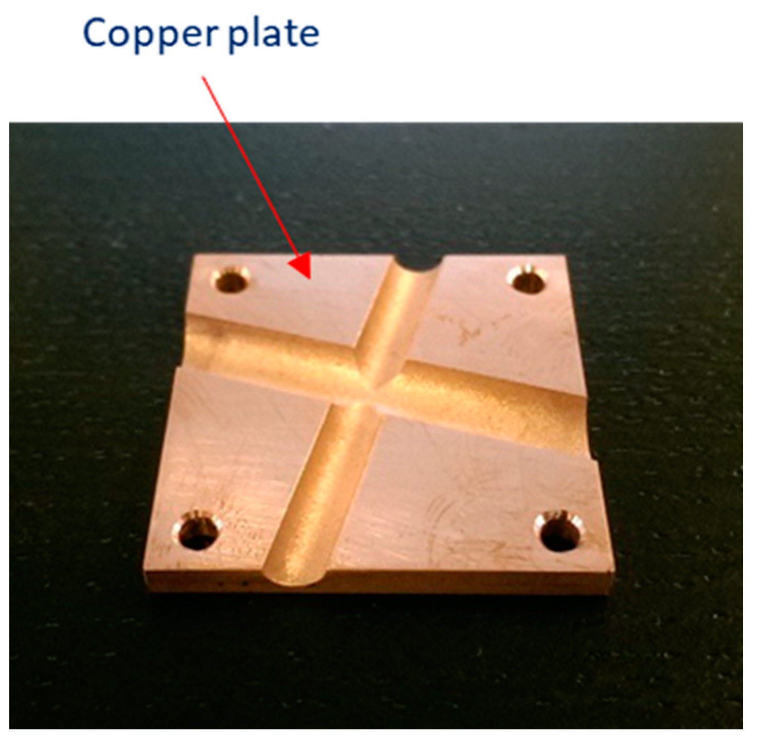
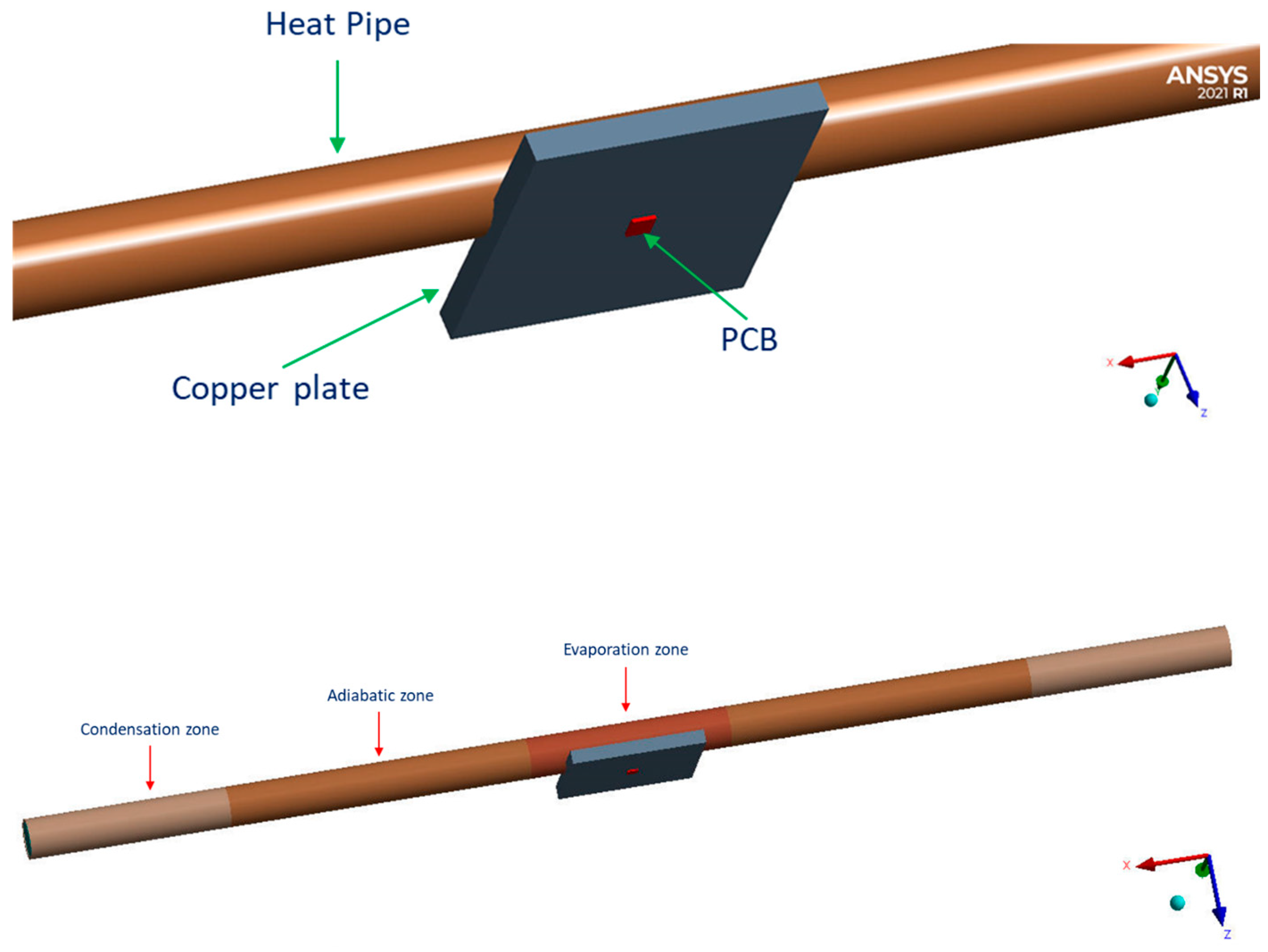
  • Heat pipes designed to cool down a Printed Circuit Board (PCB) for a generic small LEO satellite.

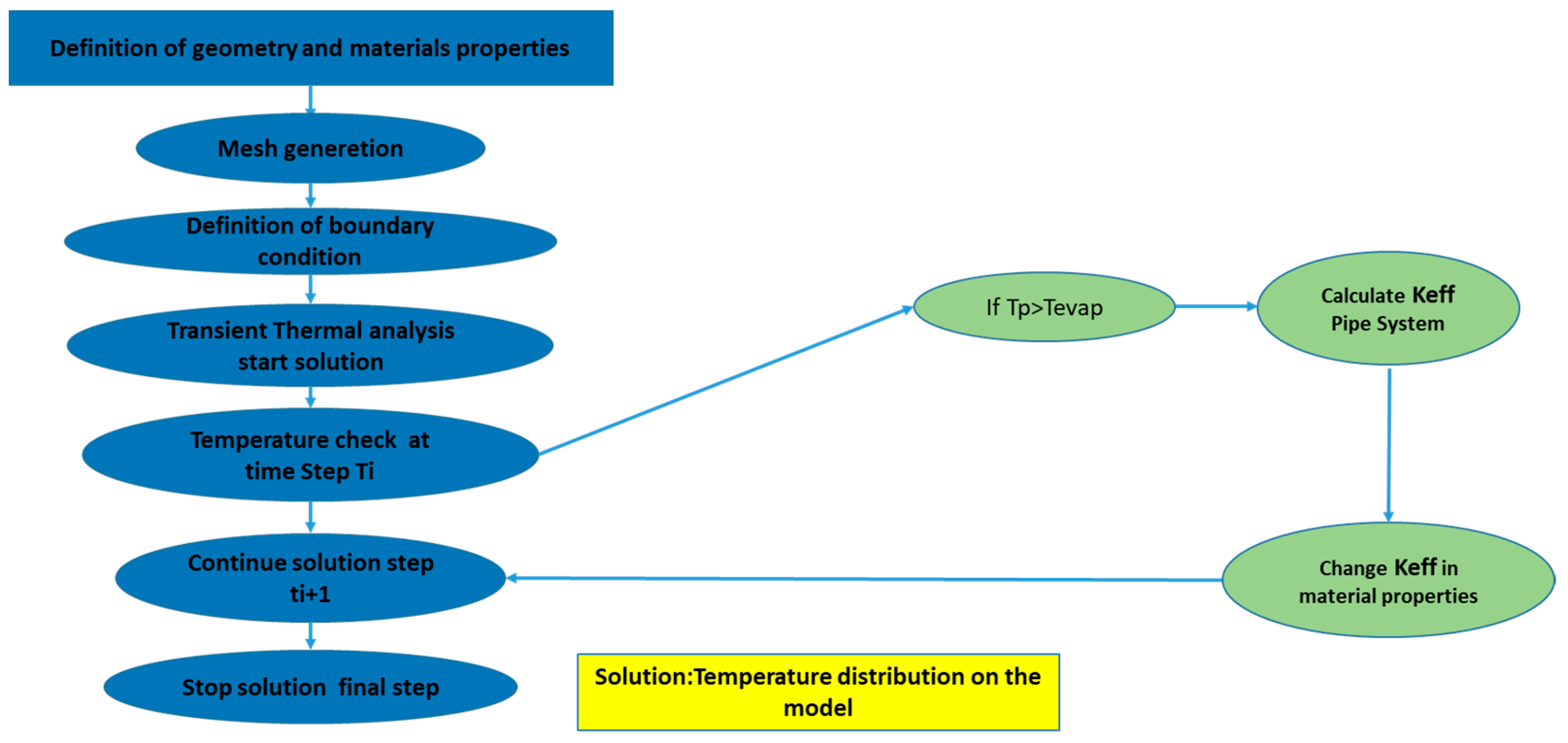
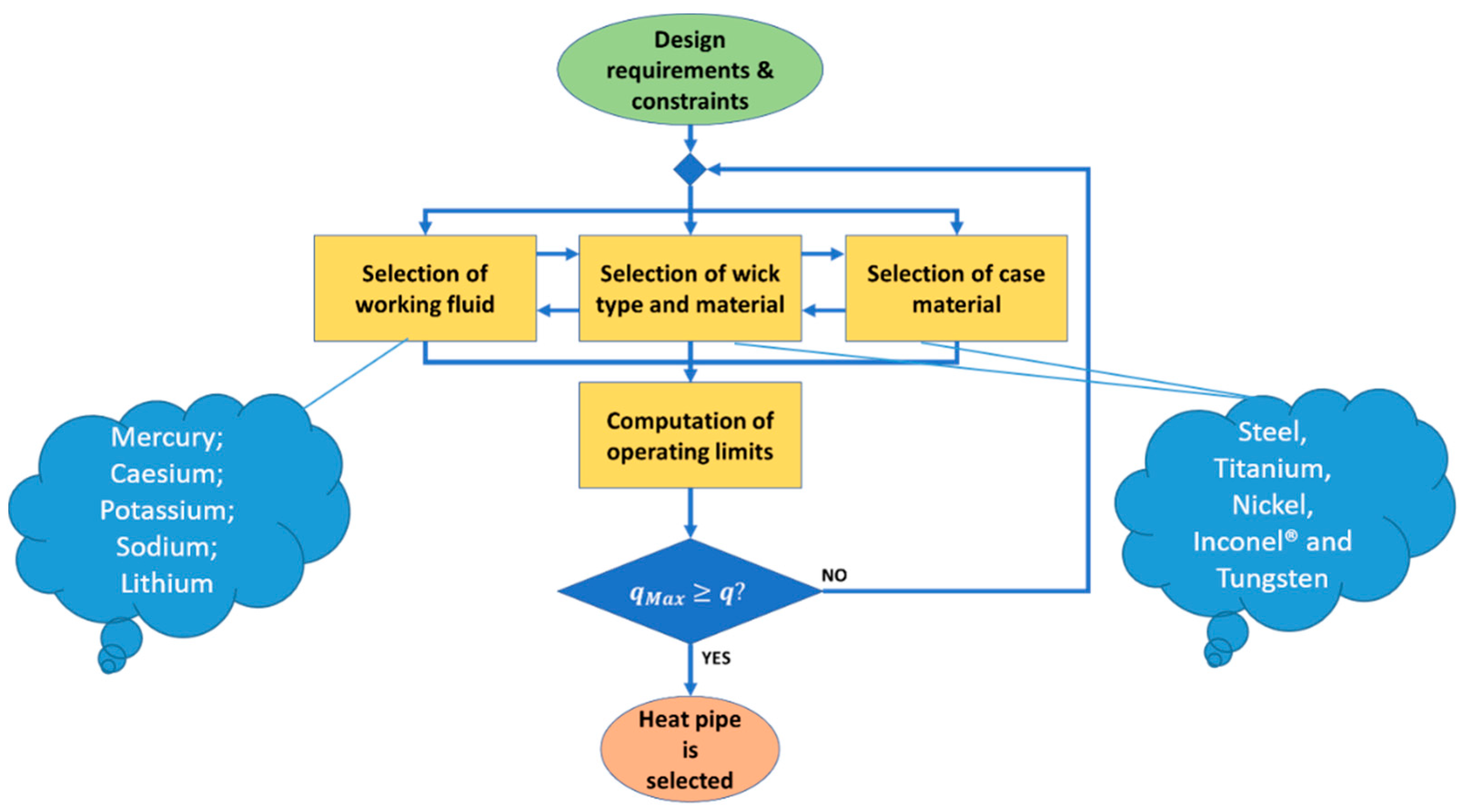
2. Development of the Numerical Tool

In order to predict a generic heat pipe thermal performance, a numerical Ansys Parametric Design Language (APDL) code [37] has been set up to verify the effective subtractive heat flux guaranteed by the selected heat pipe arrangement. The heat pipe operations can be described by a lumped parametric model based on the electrical analogy [38,39,40]. Solid components and fluid domains are subdivided into finite sub-volumes called nodes or lumps. Thermal properties and average temperature of each sub-volume are assumed to be concentrated in the relative node. Nodes are connected to each other by means of resistive, capacitive, and inductive elements modelling different physical phenomena, namely thermal or flow resistance, thermal inertia, or fluid inertia. Therefore, through the electrical analogy, the heat pipe physical system is reduced to an electrical network where the current and the electric potential represent, respectively, the thermal flux and the temperature difference between two nodes. Applying Ohm’s law and Kirchhoff’s law, an Ordinary Differential Equation (ODE) can be written for each node, thus reducing the overall transient problem to a simpler linear ODE system. In nominal conditions, the overall heat transfer rate of the heat pipe (Q) can be described using Equation (1), where ΔT is the overall temperature difference between the heat source and the heat sink, and R t o t is the idealized thermal resistance network, shown in Figure 1. The total resistance of the heat pipe R t o t is a combination of series and parallel resistances.
Q = T R t o t
However, considering that the thermal resistance of the vapor space is extremely small, in the range of 10−8 K/W, the total thermal resistance of the heat pipe can be considered strongly dependent on the conduction resistance of the heat pipe wall in the radial direction. Following these simplifications, the total power transported by the heat pipe can be defined as in Equation (2)
Q = K e f f × A h p × T L e f f
where Keff is the effective thermal conductivity [W/m K], Leff is the effective length [m], i.e., the part of the pipe that effectively works as a heat exchanger, and Ahp is the cross-sectional area [m2].
The heat pipe model, through the electrical analogy, has been implemented in a numerical code, which allows for performing a transient thermal analysis using the Mechanical APDL language that is integrated into the software ANSYS® Rel 21. The analysis has been conducted considering the “effective” thermal conductance of the pipe system, which is changed iteratively. The ANSYS® mathematical model considers that there are three basic modes of heat transfer:
  • Conduction: internal energy exchange between one body in perfect contact with another or from one part of a body to another part due to a temperature gradient.
  • Convection: energy exchange between a body and a surrounding fluid.
  • Radiation: energy transfer from a body or between two bodies by electromagnetic waves.
In many cases, we analyze heat conduction problems with some combination of convection, heat flux, specified temperature, and radiation boundary conditions.
Conduction heat transfer is defined by Fourier’s Law of Conduction:
q = K n m T n
where:
  • q = heat flow rate per unit area in direction n.
  • Knm = thermal conductivity in direction n.
  • T = temperature.
  • T n = thermal gradient in direction n.
A negative sign indicates that heat flows in the opposite direction of the gradient (i.e., heat flows from hot to cold).
Convection is typically applied as a surface boundary condition. The simplest form of convection condition requires the user to prescribe a film coefficient and fluid temperature as user inputs. In particular, convection heat transfer is defined by Newton’s Law of Cooling:
q = h ( T S T F )
where:
  • h = convective film coefficient;
  • TS = surface temperature;
  • TF = bulk fluid temperature.
Finally, radiation heat transfer is derived from the Stefan–Boltzmann Law:
Q = σ ε A i F i j ( T i 4 T j 4 )
where:
  • σ = Stefan–Boltzmann constant;
  • ε = emissivity;
  • Ai = area of surface i;
  • Fij = form factor from surface i to surface j;
  • Ti = absolute temperature of surface i;
  • Tj = absolute temperature of surface j.
Moreover, radiation in ANSYS Mechanical is treated as a surface phenomenon where bodies are assumed to be opaque.
Finally, the governing equation for the thermal analysis of a linear system is written in matrix form. The inclusion of the heat storage term differentiates transient systems from steady-state systems:
C T ˙ + K T = Q
i.e., Heat Storage Term = (Specific Heat Matrix) × (Time Derivative of Temperature).
When the response of a system over time is required (due to time-varying loads and/or boundary conditions in conjunction with thermal mass effects), a transient analysis is performed. In a transient thermal, loads vary with time, or in the case of a nonlinear transient analysis, time and temperature:
C ( T ) T ˙ + K ( T ) T = Q ( T , t )
In addition to thermal conductivity (k), density (ρ), and specific heat (λ), material properties must be specified for entities that can conduct and store thermal energy. These material properties are used to calculate the heat storage characteristics of each element, which are then combined in the Specific Heat Matrix [C]. Nonlinear solutions in ANSYS Mechanical are fundamentally based on the full Newton–Raphson iteration procedure. When performing a thermal transient analysis, a time integration procedure is also used to obtain solutions to the system equations at discrete points in time. The change in time between solutions is called the Integration Time Step (ITS). Generally, the smaller the ITS, the more accurate the solution becomes. The time integration operator is modifiable and is based on a generalized trapezoidal rule:
T n + 1 = T n + 1 θ t T ˙ n + θ t T ˙ n + 1
with θ being the Euler parameter.
The selection of a reasonable time step size is important because of its impact on solution accuracy and stability. Indeed, if the time step size is too small, then solution oscillations may occur, which could result in temperatures that are not physically meaningful (e.g., thermal undershoot), while if the time step is too large, then temperature gradients will not be adequately captured. Particular attention has been paid by the author to this issue.
The numerical code simulates the convection phenomenon as an equivalent conduction through a pipe structure, where the thermal conductivity of the overall heat pipe is calculated by Equation (3), which is a restatement of Equation (2):
K e f f = Q × L e f f A h p × ( T e v a p o r a t o r T c o n d e n s e r )
When the heat pipe is active, according to the Evaporator and Condenser section temperature, its thermal conductivity typically can range from 250 to 500 times the thermal conductivity of solid copper or aluminum, respectively. Figure 2 shows the flowchart of APDL code.
During the analysis, the code retrieves the heat flux value (Q) at the interface Heat Pipe-Internal Crotch and the temperature in the evaporator and condenser zone ( T e v a p o r a t o r , T c o n d e n s e r ) at every simulation step. A check on the temperature in the evaporator zone at each step is performed, and if T e v a p o r a t o r is higher than the boiling temperature of pipe liquid, Keff can be estimated using Equation (1), using the T c o n d e n s e r and Q associated with the current step. Once the Keff is evaluated, the conductivity of each material is updated accordingly.

3. Case Study No. 1: STRATOFLY MR3 Hypersonic Vehicle

The first test case is about STRATOFLY MR3 [41] highly integrated hypersonic vehicle, where propulsion, aerothermodynamics, structures, and on-board subsystems are strictly interrelated with one another, as highlighted in Figure 3. As already highlighted in previous publications, the thermal and energy management for this type of vehicle is crucial [42,43].
Designing a civil high-speed aircraft for passenger transportation means evaluating technical, environmental, and economic viability in combination with human factors, social acceptance, and implementation and operational aspects.
In past years, some innovative high-speed aircraft configurations have been proposed and evaluated in depth, with the main goal of demonstrating the economic viability of a high-speed aircraft fleet [44,45,46,47,48]. These concepts make use of unexploited flight routes in the stratosphere, offering a solution to the presently congested flight paths while ensuring minimal environmental impact in terms of emitted noise and greenhouse gasses, particularly during the stratospheric cruise phase. Only a dedicated multidisciplinary and highly integrated design concept could realize this, where aero-thermodynamic issues are evaluated together with structural and propulsive issues in the frame of a highly multidisciplinary project [49,50,51,52].
STRATOFLY MR3 is conceived to fly along long-haul routes, reaching Mach 8 during the cruise phase at a stratospheric altitude (h > 30,000 m) and carrying 300 passengers as payload. Figure 4a shows the reference MR2.4 flight trajectory, i.e., an antipodal route from Brussels to Sydney, while Figure 4b reports the latest results obtained for the MR3 flight trajectory thanks to the upgraded aero-propulsive database. STRATOFLY MR3 has a waverider configuration, with the engines and related air ducts completely embedded into the airframe and located at the top of the vehicle (dorsal mounted configuration) (Figure 3).
Air-intake leading edges are subjected to convective overheating due to their very small radii (about 2 mm). Therefore, ad hoc efficient cooling systems must be designed. Heat pipe systems have been chosen as the driving systems. First of all, design and sizing activities consist of the definition of feasible integrated architectures and selection of the most appropriate working fluids and compatible wick and case materials. The analysis of the heat transfer limits (the capillary, entrainment, viscosity, chocking, and boiling limits) is here suggested as a guideline for the identification of a suitable design space and rational down-selection of the most promising solution. Different alternative solutions have been thoroughly analyzed, including two different heat pipe layouts (single tubular and dual-channel architecture), five liquid metals as fluids (mercury, cesium, potassium, sodium, and lithium) and relative wick and case materials (steel, titanium, nickel, Inconel®, and tungsten) and three leading-edge materials (CMC, tungsten with low-emissivity painting, and tungsten with high-emissivity painting) (Figure 5). Considering the volumetric constraints imposed by the peculiar design of the embedded air intake of the MR3, a dedicated heat pipe architecture has been developed. This architecture has been suggested for both the lower lip as well as for the crotch air intakes. In both cases, the proximity of the foremost cryogenic tanks suggests a longitudinal orientation of the pipes parallel to the longitudinal axis of the vehicle. The 22 mm radius of the air-intake leading edges allows for the adoption of a dual-channel architecture instead of a more traditional tubular architecture. The proposed solution increases the exposed area of the evaporator, thus potentially increasing the heat transfer capability. As schematically reported in Figure 6, the suggested heat pipe architecture solution is completely integrated into the air-intake structure, assuming that the heat pipe case is perfectly bonded with the panels of the aircraft skin. Eventually, perfect bonding is also ensured between the case and the wick. Finally, it is worth noting that the rear part of the condenser region shall be properly interfaced with the tank’s external structure to guarantee the required heat rejection. Figure 6 also shows that the most promising pipe for our case would be a nickel–potassium one [37].
The numerical APDL model has been verified numerically by comparing the results in terms of heat pipe predicted subtractive heat flux w.r.t the results obtained by several parametric finite element models introduced hereafter. These FEMs have been developed to perform a parametric study aimed, on the one hand, at evaluating the pipe performance and, on the other hand, at optimizing the air-intake layout in terms of material and geometric thicknesses. A mesh convergence analysis led to a finite element model of about 5000 nodes and 1000 HEXA solid elements with an average element quality of 0.95 (Figure 7).
The following general boundary conditions have been considered (Figure 8):
  • Convective heat fluxes on external wet areas (derived by CFD calculations with a peak value of about 1.2 MW/m2 as heat transfer coefficient on the crotch);
  • Radiation to ambient for external surfaces;
  • Adiabatic wall at cut surface locations;
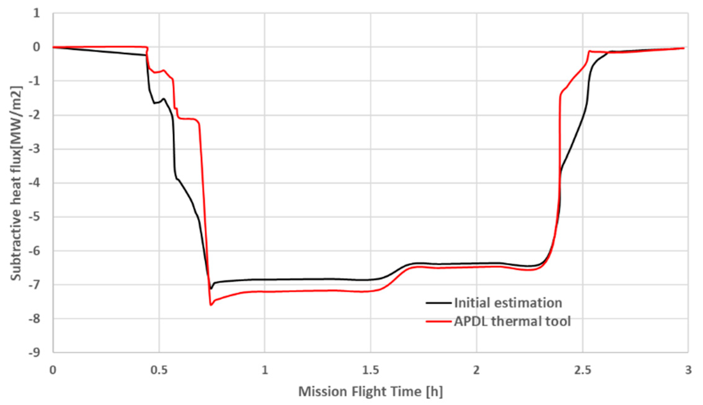
  • Subtractive heat flux applied at leading-edge internal additional part/heat pipe interface;
  • Heat pipe is modelled as a perfect contact body with the internal part of the vehicle crotch.
Three different leading-edge materials have been considered and analyzed: tungsten; tungsten coated with high-emissivity paint (ε = 0.9); and full CMC. Finally, the latter has been chosen as the best material. Indeed, different simulations have been performed, varying the subtractive heat fluxes from the pipe. This allows for checking the effect of maximum temperature on the crotch. Figure 9 shows the different fluxes whose peaks range from 700 kW/m2 for the so-called run 1 to about 950 kW/m2 for the so-called run 4. Figure 9 also shows the corresponding results in terms of maximum temperature on the crotch. It is clear that CMC acts as a very effective thermal barrier. Indeed, an increment in subtractive heat fluxes of 25% results in a 4.85% temperature reduction. Finally, run 4 conditions are retained because this scenario keeps the CMC temperature under the theoretical service operative temperature fixed at 1600 °C. Figure 10 shows the thermal map on the CMC leading edge at a maximum time instant. The temperature reaches, in this case, a peak value of 1598 °C at 2634 s. Figure 10 also shows the thermal behavior of the CMC panels.
In order to verify the effective subtractive heat flux guaranteed by the selected heat pipe arrangement, the APDL numerical code, as described in Section 2, including the pipes entirely (skin, container, and wick) and fluids, has been employed.
Simulation without heat pipe activation has also been performed in order to discriminate the contribution due to heat pipe physical installation conduction from the contribution due to heat pipe working fluid convection. Indeed, when the heat pipe is not activated, the subtracted heat flux is only due to conduction through the solid interface between the crotch and the pipe itself. On the other hand, when the pipe is activated, the overall subtractive heat flux takes into account both solid conduction and convection through the working fluid. Figure 11 shows the effective subtractive heat flux (in red) as evaluated in APDL. The average effective subtractive heat flux is about 0.72 MW/m2, and it includes both the conductive and convective heat fluxes subtracted by the heat pipe. The conductive heat flux (in black) considers only the conduction contribution guaranteed by the presence of the heat pipe itself. Complementary, in blue, is the convective subtractive heat flux due to pipe activation, which is about 0.4 MW/m2.
Finally, the value of the effective subtractive heat flux derived by pipe activation (0.72 MW/m2) is in line with the most conservative value (0.7 MW/m2) hypothesized during the thermal design step (run 1 in Figure 9) (Figure 12). This result shows the APDL numerical tool is numerically validated by the comparison.

4. Case Study No. 2: LEO Small Satellite

The evolution of the nanosatellite market in the last decade finds its origin in the introduction of the CubeSat standard. This standard, being proposed as a platform for educational and low-cost space experimentation for the industry, was quickly adopted, and its growing popularity is reflected in the increasingly yearly launch rates since its introduction. Currently, the CubeSat platform has surpassed its original purpose and is slowly winning ground over larger satellites by providing similar functionalities. Its potential has been recognized by the industry, and the demand for more high-performance missions is increasing. These forecasts predict an increase in CubeSats to be launched over the next few years, an increase in CubeSat form factor size, and a shift in the primary mission objective from education and technology demonstration towards Earth Observation (EO). The interest of the industry and the shift in mission objectives run parallel with the advances in the ongoing miniaturization trend and the development of deployable solar panels, which have paved the way for the employment of more powerful instruments, systems, and components. An extensive literature review has revealed that the power level of CubeSats is increasing rapidly and that this trend does not adhere to the mass versus power trend lines established in the past, which is shown in Figure 13, where the blue dispersed line with black dots represents the trendline that was established in the past between power consumptions and satellite masses, while some recent CubeSats are explicitly plotted [53,54,55]. The figure shows the peak power values for different CubeSat form factors. From these and other examined missions, it has been derived that peak power levels will rise to values of approximately 20 to 40 W. While a shift is visible towards larger CubeSats, such as 6 U and 12 U, the 3 U will remain popular in the next few years, especially for constellations. With these power levels, it means that power density will increase significantly, i.e., a real thermal challenge arises, and performant thermal control systems are required. The thermal challenges of CubeSats have three main causes, each leading to a different thermal problem: low thermal mass, limited surface area, and high density. The first makes the satellite rapidly responsive to thermal fluctuations, as the heat capacity is limited. This leads to thermal cyclic loading, which can be destructive for many components.
The second cause, a limited surface area, leads to problems when heat loads increase beyond the radiating capability of the outer panels. In that case, the satellite will not be able to remove all its excess heat and will continue to heat up.
The third and last property of the CubeSat platform can result in local hot-spots when heat load levels increase on, for example, electronic chips. With high heat loads on a small area and insufficient conduction paths, the local temperature will quickly rise to levels beyond the limit.
A well-designed integrated heat pipe again represents a valid thermal control solution.
The analysis of the heat transfer limits (the capillary, entrainment, viscosity, chocking, and boiling limits) has to be followed again as a guideline for the identification of a suitable design. Several parameters have to be taken into account, like the working fluids as well as the wick material and shapes (Figure 14 and Figure 15). In particular, vapor pressure and merit number are two parameters used to screen potential working fluids. Merit number is a means of ranking the heat pipe fluids. For example, the merit numbers of water and methanol are 1.63 × 10¹¹ and 1.61 × 10¹⁰. Water has a higher merit number than methanol, indicating higher surface tension and latent heat of vaporization, which are the prior requirements for high heat transfer. According to the merit number rating, water is a more effective working fluid than ethanol on the basis of heat transfer.
Working fluids used in heat pipes range from helium at 4 K up to lithium at 2300 K. For temperatures below 450 K, water is superior over the range from 300 K to 400 K, where the alternative organic fluids tend to have considerably lower merit numbers. At slightly lower temperatures, between 200 K and 300 K, ammonia is a desirable fluid, although it requires careful handling to avoid contamination, whereas acetone and alcohols are alternatives that have lower vapor pressures. These fluids are commonly used in heat pipes for space applications. Water and methanol, both compatible with copper, are often used for cooling electronic equipment [53].
For LEO satellites, the most common commercial heat pipes are either aluminum-ammonia or copper-water.
Since the paper’s main objective is to verify that the APDL internally developed numerical code can be used to predict the behavior of a generic designed pipe, we decided to numerically reproduce a literature experimental test [53]. The test is started by setting the thermal chamber to a temperature of 40 °C. The setup is left until the outer panels reach a steady-state temperature of 40 °C. Once this situation has been reached, a heat load is applied, and time is given to the test object to reach a steady state again. The heat load was incremented in steps dependent on the thermal response of the PCB (mainly to prevent overheating and destroying the test object). As it is expected that the satellite’s outer panels will see a rise in temperature due to the internal heat load, the chamber is actively controlled to maintain the panel boundary temperature at 40 °C.
In particular, a copper-water heat pipe has been integrated into a 2 U CubeSat structure and tested in a thermally controlled environment with a heat source capable of generating heat load. The limited room available within the CubeSat limits the freedom of integrating a heat pipe into the platform; therefore, the structural frame ribs are usually used as a heat sink (Figure 16). To ensure a high heat-transfer coefficient, the contacting area between the frame rib and the heat pipe is maximized by employing a simple rectangular element in which the heat pipe is slit. This piece is then clamped by using an aluminum strip that uses the present screw holes, which are normally occupied by the screws, which in turn attach the outer panels to the frame structure. The heat generated by the heat source (the Printed Circuit Board—PCB) needs to be transferred to the heat pipe as efficiently as possible to prevent the occurrence of a large thermal gradient. For this reason, a copper plate fitting the dimensions of the heat source and heat pipe is designed to act as an efficient interface (Figure 17). The theoretical analyses and experimental performance characterization of the different heat pipes have shown that a heat pipe is required with an outer diameter of at least 6 mm. Moreover, a 300 mm sintered heat pipe length has been considered and integrated into the test article [53].
Several finite element models have been developed, starting from a pipe schematic geometry (Figure 18).
The geometry reproduces the experimental scheme in a simplified way, with a 6 mm diameter heat pipe housed on a heat-dissipating chip with an area of 20 × 20 mm.
A mesh convergence analysis led to a finite element model of about 50,000 nodes and 1000 HEXA solid elements with an average element quality of about 0.95 (Figure 19).
The following general boundary conditions have been considered (Figure 20):
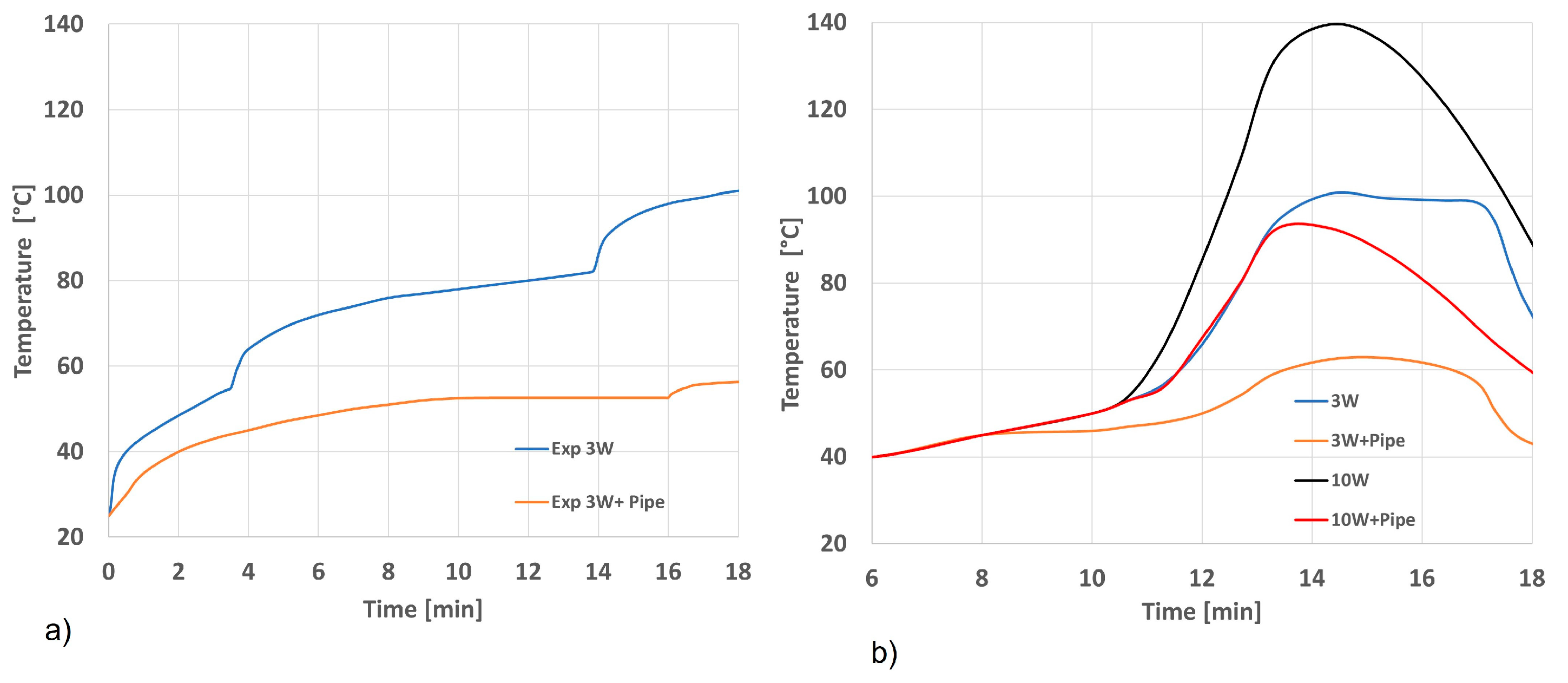
  • Stepwise heat fluxes applied from PCB center (heat fluxes corresponding to the PCB dissipated energy, i.e., 3 W and 10 W at peak);
  • Constant conservative temperature applied at the pipe edges.
The following Table 1 summarizes the material properties considered in the FEM for the different components/parts.
Results in terms of temperature measured at the center and along the PCB are compared with respect to those predicted numerically. Figure 21a shows measured temperatures along the PCB without and with a heat pipe, while Figure 21b shows maximum temperatures predicted numerically without and with a heat pipe for two different inputs (3 W and 10 W).
In particular, it can be noticed from the results in Figure 21 how the trends of the numerical curves fit quite well with the 3 W experimental ones up to the peak values. Moreover, these peaks differ by about 8% in absolute values (Table 2). Finally, it can be considered that results show a very good accordance in validating the APDL numerical tool that was developed.

5. Conclusions

Even though the most recent literature works reveal that many numerical models have been developed, they are all tailored to very specific geometries and built to investigate details of functioning. One of the criticalities of these approaches is that they easily fail in predicting performance when applied to other aerospace configurations and/or thermal environments. Moreover, the very high level of detail usually prevents the exploitation of these models in the early conceptual design phases. To overcome the highlighted issues, this paper has disclosed a novel numerical tool for the design and thermal performance assessment of generic heat pipes to be easily integrated into a conceptual design activity flow. To achieve this goal, a numerical Ansys Parametric Design Language (APDL) code was set up to verify the effective subtractive heat flux guaranteed by a heat pipe arrangement selected through a trade-off supported by analytical studies. In particular, in order to verify the versatility of the developed numerical tool, the paper reports the application in two very different case studies.
The first test case is about the STRATOFLY MR3 highly integrated hypersonic vehicle, where propulsion, aerothermodynamics, structures, and on-board subsystems are strictly interrelated with each other. In this case, air-intake leading edges are subjected to convective overheating due to their very small radii (about 2 mm). Therefore, ad hoc efficient cooling systems must be designed. Heat pipe systems have been chosen as the driving systems. The heat pipe design process, as well as the material layout choice supporting FEM analysis for the vehicle crotch, were highlighted, and finally, thermal performance was evaluated numerically using the developed APDL tool.
The second test case deals with a standard LEO satellite. A standard copper-water heat pipe was considered, and a numerical experimental validation was carried out. In particular, a literature experimental test was reproduced [53]. In particular, a heat pipe was integrated into a 2U CubeSat structure and tested in a thermally controlled environment with a heat source capable of generating heat load. Numerical results show a very good accordance, validating the numerical tool. Indeed, peaks differ by only about 8% w.r.t maximum temperature values predicted on the PCB at the evaporator section interface.
The main results show the developed numerical tool is extremely versatile. Indeed, the chosen test cases are very different from each other in terms of aerothermal environment, test-article sizing, and geometrical shape. Moreover, the employed heat pipes were designed with different wick and case materials, as well as different working fluids. In both cases, the tool correctly predicts the thermal performance.
However, the code requires some expertise to be used. Further development will lead to a global simplification with the aim of making it user-friendly.

Author Contributions

Conceptualization, R.S. and V.D.S.; methodology, R.S., V.D.S. and R.F.; software, R.S. and V.D.S.; validation, R.S., V.D.S. and D.F.; resources, R.S., R.F. and V.D.S.; data curation, R.S. and V.D.S.; writing—original draft preparation, R.S. and R.F.; writing—review and editing, R.S., R.F. and V.D.S.; project administration, N.V.; funding acquisition, N.V. All authors have read and agreed to the published version of the manuscript.

Funding

The first part of this research was funded by the European Union’s Horizon 2020 research and innovation programme under grant agreement No 769246—Stratospheric Flying Opportunities for High-Speed Propulsion Concepts (STRATOFLY) Project.

Data Availability Statement

Data are contained within the article.

Conflicts of Interest

The authors declare no conflicts of interest.

Abbreviations

Ahp Cross - sec tional   area   of   the   overall   heat   pipe   m 2
AiArea of surface i
ΔTOverall temperature difference between the heat source and the heat sink [K]
εEmissivity [−]
FijForm factor from surface i to surface j
hConvective film coefficient
KeffEffective liquid/wick conductivity [W/m K]
KnmThermal conductivity in direction n
LeffEffective heat pipe length [m]
QOverall heat transfer rate [W]
RtotOverall thermal resistance [K/W]
σStefan–Boltzmann constant
θEuler parameter
TcondencerTemperature of the working fluid in the condenser section [K]
TevporatorTemperature of the working fluid in the evaporator section [K]
TSSurface temperature
TFBulk fluid temperature
TIAbsolute temperature of surface i
TjAbsolute temperature of surface j
Acronyms
APDLAnsys Parametric Design Language
CCHPConstant Conductance Heat Pipe
CFDComputational Fluid Dynamics
CMCCeramic Matrix Composite
FEMFinite Element Method
MLIMulti-Layer Insulation
NASPNational Aerospace Plane program
NePCMNano-enhanced phase change material
OHPOscillating Heat Pipe
PCMPhase Change Material
PCBPrinted Circuit Board
TCSThermal control system
VCHPVariable Conductance Heat Pipe

References

  1. Figueiras, I.; Coutinho, M.; Afonso, F.; Suleman, A. On the Study of Thermal-Propulsive Systems for Regional Aircraft. Aerospace 2023, 10, 113. [Google Scholar]
  2. Eisenhut, D.; Moebs, N.; Windels, E.; Bergmann, D.; Geiß, I.; Reis, R.; Strohmayer, A. Aircraft Requirements for Sustainable Regional Aviation. Aerospace 2021, 8, 61. [Google Scholar]
  3. Viswanathan, V.; Knapp, B.M. Potential for electric aircraft. Nat. Sustain. 2019, 2, 88–89. [Google Scholar] [CrossRef]
  4. Van Heerden, A.; Judt, D.; Jafari, S.; Lawson, C.; Nikolaidis, T.; Bosak, D. Aircraft thermal management: Practices, technology, system architectures, future challenges, and opportunities. Prog. Aerosp. Sci. 2022, 128, 100767. [Google Scholar]
  5. Freeman, J.; Osterkamp, P.; Michael Green, A.G.; Schiltgen, B. Challenges and opportunities for electric aircraft thermal management. Aircr. Eng. Aerosp. Technol. 2014, 86, 519–524. [Google Scholar] [CrossRef]
  6. Hirschel, E.H. Basics of Aerothermodynamics, 2nd ed.; Springer: Berlin/Heidelberg, Germany, 2015. [Google Scholar]
  7. Hirschel, E.H.; Weiland, C. Selected Aero-Thermodynamic Design Problems of Hypersonic Flight Vehicles; Springer: Berlin/Heidelberg, Germany, 2009. [Google Scholar]
  8. Viola, N.; Ferretto, D.; Fusaro, R.; Scigliano, R. Performance Assessment of an Integrated Environmental Control System of Civil Hypersonic Vehicles. Aerospace 2022, 9, 201. [Google Scholar] [CrossRef]
  9. Kun, L.; Zekuan, L.; Jing, X.; He, L.; Shiyi, X.; Cong, W.; Jiang, Q. Evaluation of high-speed aircraft thermal management system based on spray cooling technology: Energy analysis, global cooling, and multi-objective optimization. Appl. Therm. Eng. 2023, 229, 120632. [Google Scholar] [CrossRef]
  10. Silverstein, C.C. A Feasibility Study of Heat-Pipe-Cooled Leading Edges for Hypersonic Cruise Aircraft; National and Space Administration (NASA): Washington, DC, USA, 1971; NASA/CR-1857. [Google Scholar]
  11. Camarda, C.J. Analysis and Radiant Heating Tests of a Heat-Pipe-Cooled Leading Edge; National and Space Administration (NASA): Washington, DC, USA, 1977; NASA/TN D.-8468. [Google Scholar]
  12. Camarda, C.J. Application of Formal Optimization Techniques in Thermal/Structural Design of a Heat-Pipe-Cooled Panel for a Hypersonic Vehicle; National and Space Administration (NASA): Washington, DC, USA, 1987; NASA/TM-81931. [Google Scholar]
  13. Glass, D.E.; Merrigan, M.A.; Sena, J.T. Fabrication and Testing of a Leading-Edge-Shaped Heat Pipe; National and Space Administration (NASA): Washington, DC, USA, 1998; NASA/CR-208720. [Google Scholar]
  14. Steeves, G.A.; He, M.Y.; Kasen, S.D. Feasibility of metallic structural heat pipes as sharp leading edges for hypersonic vehicles. J. Appl. Mech. 2009, 76, 031014. [Google Scholar]
  15. Xiao, G.; Du, Y.; Gui, Y.; Liu, L.; Yang, X.; Wei, D. Heat transfer characteristics and limitations analysis of heat- pipecooled thermal protection structure. Appl. Therm. Eng. 2014, 70, 655–664. [Google Scholar]
  16. Glass, D.E. Ceramic Matrix Composite (CMC) Thermal Protection Systems (TPS) and Hot Structures for Hypersonic Vehicles. In Proceedings of the 15th AIAA Space Planes and Hypersonic Systems and Technologies Conference AIAA, Dayton, OH, USA, 28 April–1 May 2008. [Google Scholar] [CrossRef]
  17. Faghri, A. Heat Pipe Science and Technology; CRC Press: New York, NY, USA, 1995. [Google Scholar]
  18. Meseguer, J.; Pérez-Grande, I.; Sanz-Andrés, A. Spacecraft Thermal Control; Whoodhead Publishing Limited: Cambridge, UK, 2012. [Google Scholar]
  19. Sharifi, N.; Roesler, D.; Gold, A.; Shabgard, H. Thermal Management System for Lithium-Ion Batteries Using Phase Change Material, Heat Pipes and Fins. In Proceedings of the International Mechanical Engineering Congress and Exposition IMECE 2023, New Orleans, LA, USA, 29 October–2 November 2023. [Google Scholar]
  20. Faraji, H.; Alami, M.E.; Arshad, A.; Hariti, Y. Numerical Survey on Performance of Hybrid NePCM for Cooling of Electronics: Effect of Heat Source Position and Heat Sink Inclination. J. Thermal Sci. Eng. Appl. 2021, 13, 051010. [Google Scholar] [CrossRef]
  21. Arshad, A.; Jabbal, M.; Faraji, H.; Talebizadehsardari, P.; Bashir, M.A.; Yan, Y. Numerical study of nanocomposite phase change material-based heat sink for the passive cooling of electronic components. Heat Mass Transfer 2021. [Google Scholar] [CrossRef]
  22. Hu, C.; Yu, D.; He, M.; Li, T.; Yu, J. Design and Verification of Ultra-High Temperature Lithium heat pipe based experimental facility. Therm. Sci. 2022, 26, 3413–3426. [Google Scholar] [CrossRef]
  23. Ababneh, M.; Tarau, C.; Anderson, W.; Farmer, J. Thermal Control of Lunar and Mars Rovers/Landers Using Hybrid Heat Pipes. J. Thermophys. Heat Transf. 2019, 33, 705–713. [Google Scholar]
  24. Miesner, S.; Wolk, K.; Furst, B.; Daimaru, T.; Sunada, E.; Roberts, S.; Bellardo, J.; Kuo, J. Thermal Testing of An Amdrohp (Additively Manufactured Deployable Radiator Oscillating Heat Pipes) for Use in High-Powered Cubesats. In Proceedings of the International Mechanical Engineering Congress and Exposition IMECE2023, New Orleans, LA, USA, 29 October–2 November 2023. [Google Scholar]
  25. Iwata, N.; Saitoh, M.; Yanagase, K.; Iso, Y.; Inoue, Y.; Ogawa, H.; Miyazaky, Y. Thermal and Structural Performance of a Small Satellite with Networked Oscillating Heat Pipes. J. Spacecr. Rocket. 2022, 59, 1016–1028. [Google Scholar]
  26. Niblock, G.A.; Reeder, J.C.; Huneidi, F. Four space shuttle wing leading edge concepts. J. Spacecr. Rocket. 1974, 11, 314–320. [Google Scholar] [CrossRef]
  27. Tang, H.; Lian, L.; Zhang, J.; Liu, Y. Heat transfer performance of cylind- rical heat pipes with axially graded wick at anti-gravity orientations. Appl. Therm. Eng. 2019, 163, 114413. [Google Scholar] [CrossRef]
  28. Nazari, M.A.; Ghasempour, R.; Ahmadi, M.H. A review on using nanofluids in heat pipes. J. Therm. Anal. Calorim. 2019, 137, 1847–1855. [Google Scholar] [CrossRef]
  29. Koito, Y. Numerical analyses on heat transfer characteristics of ultra-thin heat pipes: Fundamental studies with a three-dimensional thermal-fluid model. Appl. Therm. Eng. 2019, 148, 430–437. [Google Scholar] [CrossRef]
  30. Liao, G.; Liu, L.; Zhang, F.; Jiaqiang, E.; Chen, J. A comparison of numerical investigations on the flow and heat transfer characteristics in the rotor- stator cavity. Appl. Therm. Eng. 2019, 162. [Google Scholar] [CrossRef]
  31. Liu, H.; Liu, W. A numerical model for the platelet heat-pipe-cooled leading edge of hypersonic vehicle. Acta Astronaut. 2016, 118, 210–217. [Google Scholar] [CrossRef]
  32. Liu, H.; Liu, W. Thermal–structural analysis of the platelet heat-pipe-cooled leading edge of hypersonic vehicle. Acta Astronaut. 2016, 127, 13–19. [Google Scholar]
  33. Yin, L.; Liu, H.; Liu, W. Capillary character and evaporation heat transfer in the wicks of high temperature liquid metal heat pipe. Appl. Therm. Eng. 2020, 175, 115284. [Google Scholar] [CrossRef]
  34. Ranjan, R.; Murthy, J.Y.; Garimella, S.V. A microscale model for thin-film evaporation in capillary wick structures. Int. J. Heat Mass Transf. 2011, 54, 169–179. [Google Scholar]
  35. Ryu, S.; Lee, W.; Nam, Y. Heat transfer and capillary performance of dual-height super hydrophilic micro post wicks. Int. J. Heat Mass Transf. 2014, 73, 438–444. [Google Scholar] [CrossRef]
  36. Tokuda, D.; Inoue, T. Heat transport characteristics of a sodium oscillating heat pipe: Thermal performance. Int. J. Heat Mass Transf. 2022, 196, 123281. [Google Scholar] [CrossRef]
  37. Fusaro, R.; Ferretto, D.; Viola, N.; Scigliano, R.; De Simone, V.; Marini, M. Liquid Metals Heat-Pipe solution for hypersonic air-intake leading edge: Conceptual design, numerical analysis and verification. Acta Astronaut. 2022, 197, 336–352. [Google Scholar] [CrossRef]
  38. El-Nasr, A.; El-Haggar, S.M. Effective Thermal Conductivity of Heat Pipes, Heat and Mass Transfer; Springer: Berlin/Heidelberg, Germany, 1996; pp. 97–101. [Google Scholar]
  39. Peterson, G.P. An Introduction to Heat Pipes: Modeling, Testing, and Applications; Wiley: Hoboken, NJ, USA, 1994. [Google Scholar]
  40. Iorizzo, F. Coupling of Lumped and Distributed Parameter Models for Numerical Simulation of A Sintered Heat Pipe. Master Thesis, Politecnico di Milano (POLIMI), Milano, Italy, 2011. [Google Scholar]
  41. Viola, N.; Fusaro, R.; Ferretto, D.; Gori, O.; Saracoglu, B.; Ispir, A.C.; Schram, C.; Grewe, V.; Plezer, J.F.; Martinez, J.; et al. H2020 STRATOFLY Project: From Europe to Australia in less than 3 hours. In Proceedings of the 32nd Congress of the International Council of the Aeronautical Sciences, Shanghai, China, 6–10 September 2021. [Google Scholar]
  42. Ferretto, D.; Viola, N. Preliminary design and simulation of a thermal management system with integrated secondary power generation capability for a Mach 8 aircraft concept exploiting liquid hydrogen. Aerospace 2023, 10, 180. [Google Scholar] [CrossRef]
  43. Fusaro, R.; Ferretto, D.; Viola, N.; Villace, V.; Steelant, J. A methodology for preliminary sizing of a Thermal and Energy Management System for a hypersonic vehicle. Aeronaut. J. 2019, 123, 1508–1544. [Google Scholar] [CrossRef]
  44. Villace, V.F.; Steelant, J. The Thermal Paradox of Hypersonic Cruisers. In Proceedings of the 20th AIAA International Space Planes and Hypersonic Systems and Technologies Conference, Glasgow, UK, 6–9 July 2015. [Google Scholar] [CrossRef]
  45. Steelant, J. ATLLAS: Aero-thermal loaded material investigations for high-speed vehicles. In Proceedings of the 15th AIAA International Space Planes and Hypersonic Systems and Technologies Conference, Dayton, OH, USA, 28 April–1 May 2008; p. 2582. [Google Scholar]
  46. Steelant, J.; Langener, T.; Hannemann, K.; Marini, M.; Serre, L.; Bouchez, M.; Falempin, F. Conceptual Design of the High-Speed Propelled Experimental Flight Test Vehicle HEXAFLY. In Proceedings of the 20th AIAA International Space Planes and Hypersonic Systems and Technologies Conference, Glasgow, Scotland, 6–9 July 2015. [Google Scholar]
  47. Steelant, J.; Varvill, R.; Defoort, S.; Hannemann, K.; Marini, M. Achievements Obtained for Sustained Hypersonic Flight within the LAPCAT-II Project. In Proceedings of the 20th AIAA International Space Planes and Hypersonic Systems and Technologies Conference, Glasgow, Scotland, 6–9 July 2015. [Google Scholar]
  48. Di Benedetto, S.; Di Donato, M.P.; Rispoli, A.; Pezzella, G.; Scigliano, R.; Nebula, F.; Cristillo, D.; Marini, M.; Cardone, S.; Steelant, J.; et al. Multidisciplinary Design and Flight Test of the HEXAFLY-INT Experimental Flight Vehicle Hexafly-Int. In Proceedings of the HiSST: International Conference on High-Speed Vehicle Science Technology, Moscow, Russia, 26–29 November 2018. [Google Scholar]
  49. Andro, J.Y.; Scigliano, R.; Kallembach, A.; Steelant, J. Thermal Management of the Hexafly-Int Hypersonic Glider. In Proceedings of the HiSST: International Conference on High-Speed Vehicle Science Technology, Moscow, Russia, 26–29 November 2018. [Google Scholar]
  50. Scigliano, R.; Di Benedetto, S.; Marini, M.; Villace, V.; Steelant, J. Hexafly-Int Hypersonic Vehicle Thermal Protection System Design. In Proceedings of the 71st International Astronautical Congress (IAC)—The CyberSpace Edition, Online, 12–14 October 2020. IAC-20-56572. [Google Scholar]
  51. Scigliano, R.; Pezzella, G.; Di Benedetto, S.; Marini, M.; Steelant, J. HEXAFLY-INT Experimental Flight Test Vehicle (EFTV) Aero-Thermal Design. In Proceedings of the ASME International Mechanical Engineering Congress & Exposition (IMECE), Tampa, FL, USA, 3–9 November 2017. IMECE2017-70392. [Google Scholar]
  52. Viola, N.; Fusaro, R.; Saracoglu, B.; Schram, C.; Grewe, V.; Martinez, J.; Marini, M.; Hernandez, S.; Lammers, K.; Vincent, A.; et al. Main challenges and goals of the H2020 STRATOFLY project. Aerotec. Missili Spazio 2021, 100, 95–110. [Google Scholar] [CrossRef]
  53. Brouwer, H.S.B. Performance Characterization of Water Heat Pipes and their Application in CubeSats Solving the Thermal Challenge of Next Generation CubeSats. Master Thesis, Delft University of Technology, Delft, The Netherlands, 18 May 2016. [Google Scholar]
  54. Van Es, J.; Pauw, A.; Van den Berr, R.; Van Kleef, A. Micro-pumped cooling loop to standardize micro-sat thermal control. In Proceedings of the 69th International Astronautical Congress (IAC), Bremen, Germany, 1–5 October 2018. IAC-18, C2,7,3x42197. [Google Scholar]
  55. Weeren, H.; Brake, M.T.; Hamann, R.; Holl, G.; Price, S. Thermal Aspects of Satellite Downscaling. J. Thermophys. Heat Transf. 2009, 23, 592. [Google Scholar]
  56. Brower, H.; Van Gerner, H.; Guo, J. Solving the Thermal Challenge in Power-Dense CubeSats with Water Heat Pipes. In Proceedings of the 31st Annual AIAA/USU Conference on Small Satellites, Logan, Utah, USA, 5–10 August 2017. SSC17-VII-06. [Google Scholar]
Figure 1. Heat pipe lumped parametric model.
Aerospace 11 00085 g001
Figure 2. Flowchart of the simulation process.
Aerospace 11 00085 g002
Figure 3. STRATOFLY MR3 arrangement constraints within the air-intake leading edges.
Aerospace 11 00085 g003
Figure 4. (a) Reference MR2.4 flight trajectory and (b) MR3 flight trajectory with new aero-propulsive database.
Aerospace 11 00085 g004
Figure 5. Heat pipe design logic.
Aerospace 11 00085 g005
Figure 6. Overall heat pipe arrangement for the selected case study.
Aerospace 11 00085 g006
Figure 7. Crotch 3D mesh.
Aerospace 11 00085 g007
Figure 8. FEM boundary conditions.
Aerospace 11 00085 g008
Figure 9. (a) Subtractive heat fluxes from heat pipe; (b) maximum temperature evolution at CMC crotch w.r.t different subtractive heat fluxes.
Aerospace 11 00085 g009
Figure 10. Maximum temperature evolution at CMC crotch and at CMC leeward side and windward side panel.
Aerospace 11 00085 g010
Figure 11. Average heat flux evolution at crotch–pipe interface w.r.t different thermal physics involved.
Aerospace 11 00085 g011
Figure 12. Comparison of subtractive heat flux estimation via APDL with reference to the initial guess.
Aerospace 11 00085 g012
Figure 13. Mass versus power trendline for satellites (modified by including data from some state-of-the-art CubeSat missions) [54].
Aerospace 11 00085 g013
Figure 14. Merit numbers for different heat pipe fluids [56].
Aerospace 11 00085 g014
Figure 15. Axial groove, mesh, and sintered cross-section [56].
Aerospace 11 00085 g015
Figure 16. Heat pipe integration design in a single CubeSat stack.
Aerospace 11 00085 g016
Figure 17. Evaporator copper plate sections [53].
Aerospace 11 00085 g017
Figure 18. Heat pipe geometry.
Aerospace 11 00085 g018
Figure 19. Heat pipe test mesh.
Aerospace 11 00085 g019
Figure 20. Boundary conditions.
Aerospace 11 00085 g020
Figure 21. Temperature measured at the center of the PCB (a) w.r.t those predicted numerically (b).
Aerospace 11 00085 g021
Table 1. Material properties for the different components/parts.
ComponentK (W m−1 C−1)Cp (J kg−1 C−1)Density (Kg m−3)
Pipe copper
(case and wick)
3853858930
Copper plate3853858930
Water liquid 0.64182998.2
PCB353852700
Table 2. Comparison of numerical data and experimental temperatures in °C of the PCB.
Component3 W EXP3 W + Pipe EXP3 W Numerical3 W + Pipe Numerical10 W + Pipe EXP10 W Numerical10 W + Pipe Numerical
PCB103.1057.46996295.7513992
Disclaimer/Publisher’s Note: The statements, opinions and data contained in all publications are solely those of the individual author(s) and contributor(s) and not of MDPI and/or the editor(s). MDPI and/or the editor(s) disclaim responsibility for any injury to people or property resulting from any ideas, methods, instructions or products referred to in the content.

