
A Solar Thermal Steam Propulsion System Using Disassociated Steam for Interplanetary Exploration

 ,
,
Abstract
:1. Introduction
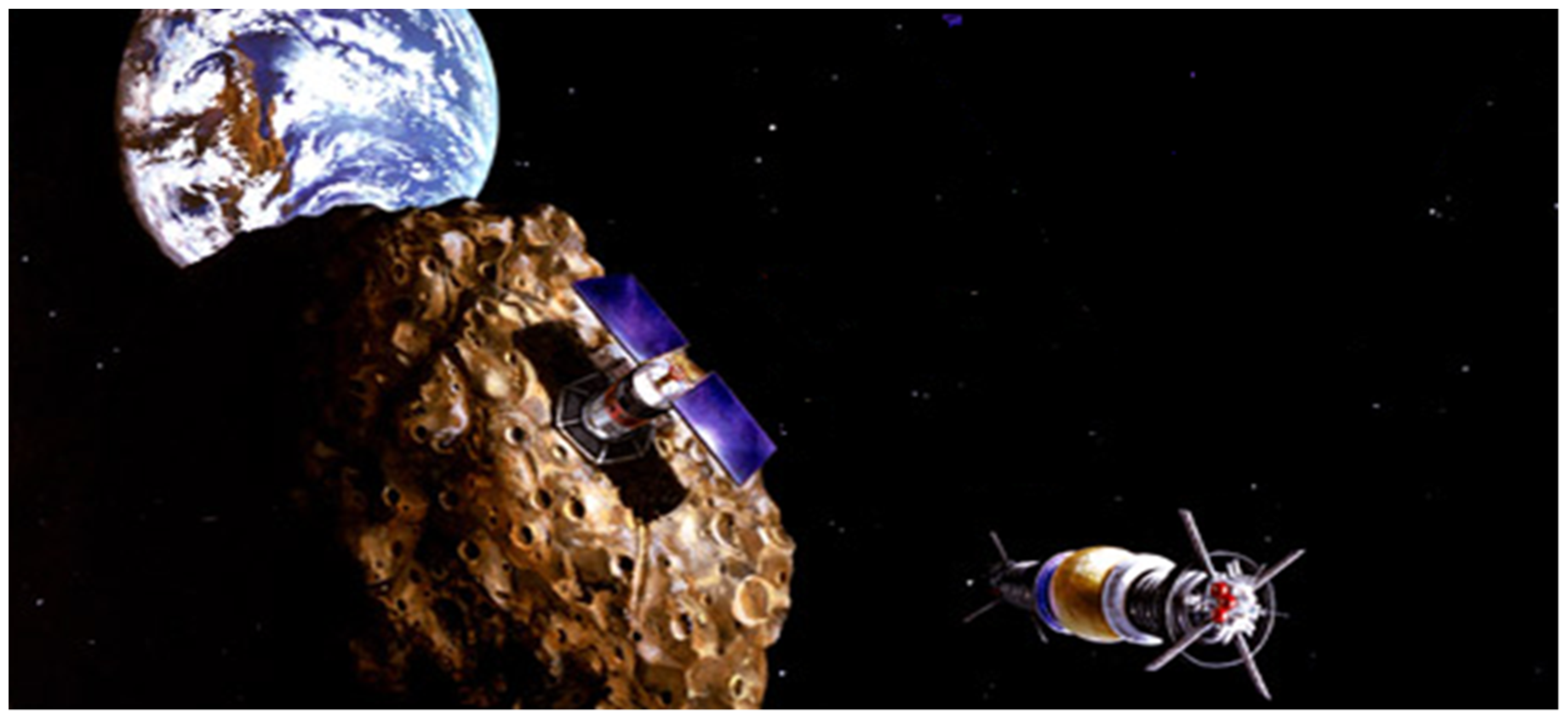
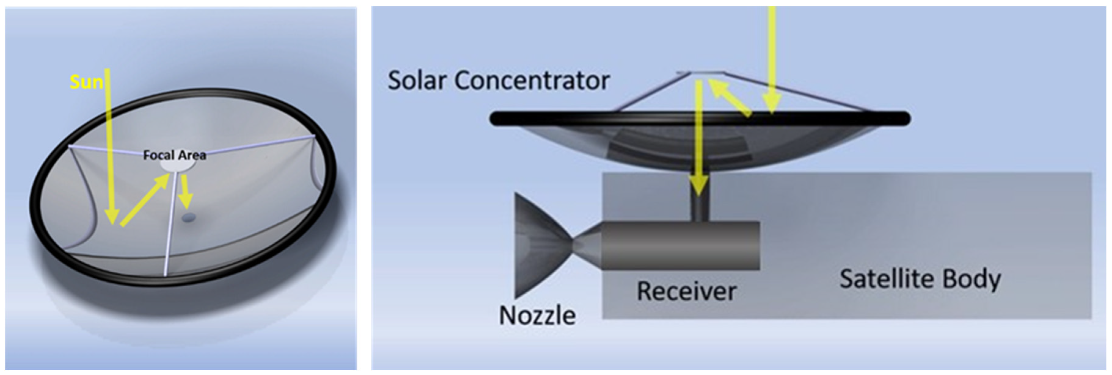
Description of Proposed System
2. Background and Related Work
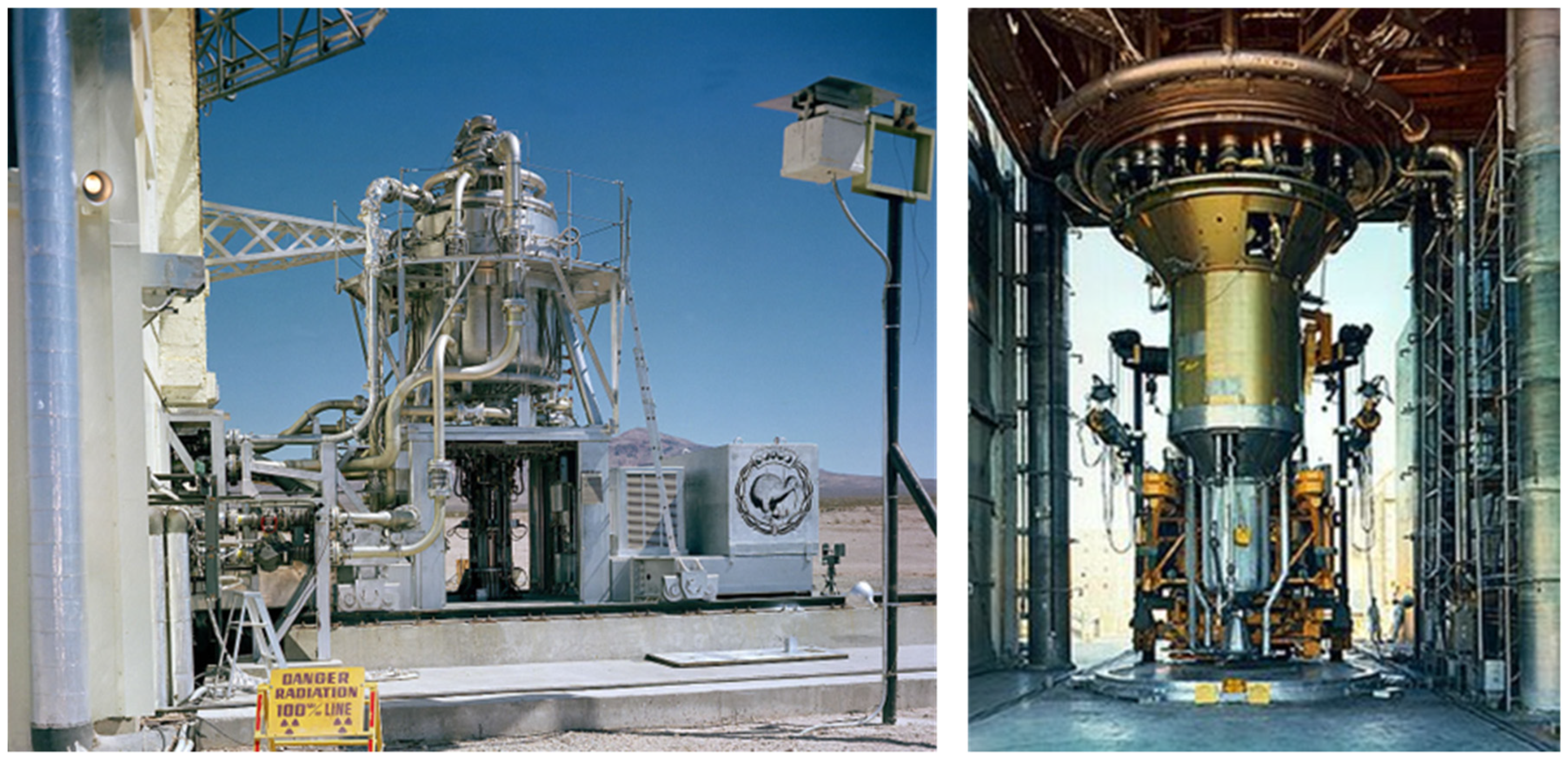
2.1. Thermal Rockets and Electrolyzing Systems
2.2. Electrolyzing Systems
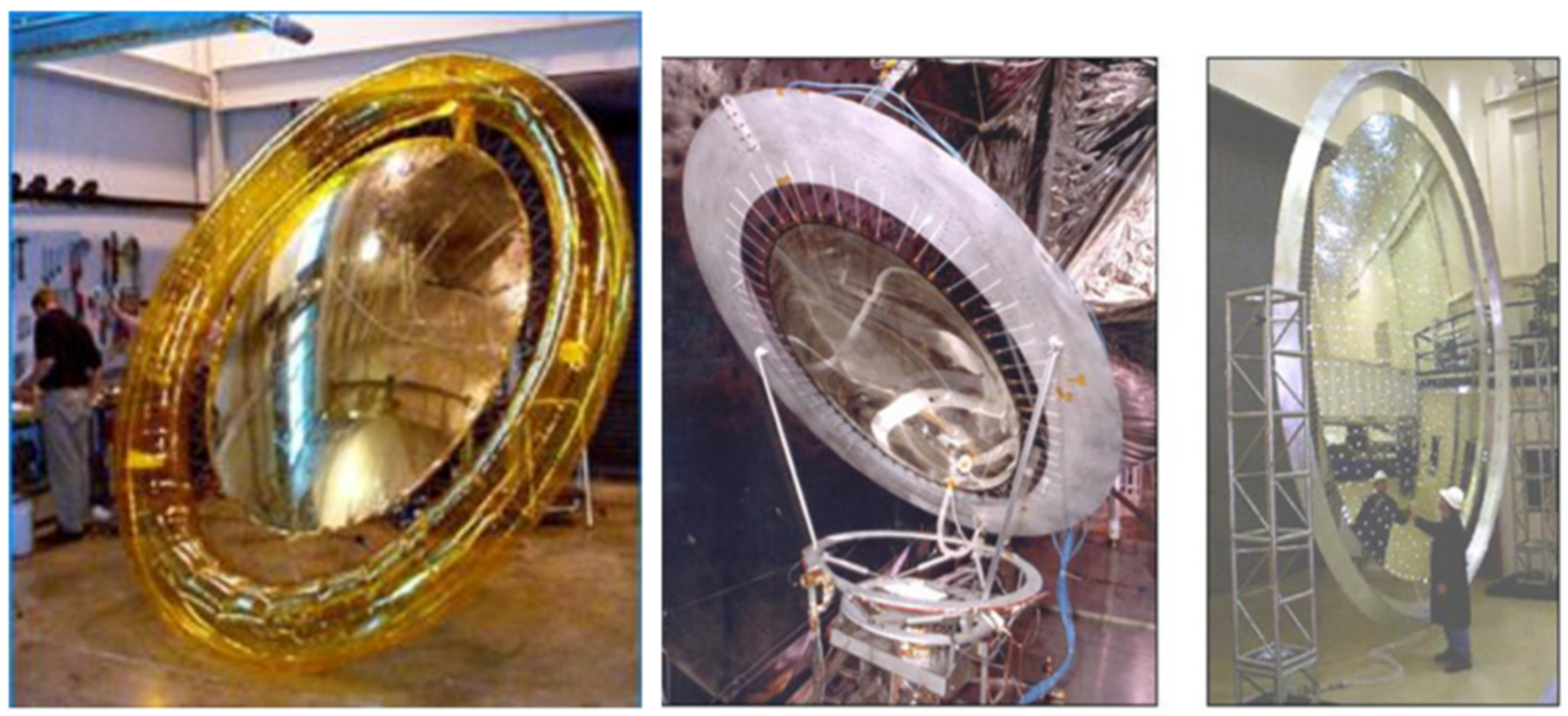
2.3. Solar Thermal Technologies
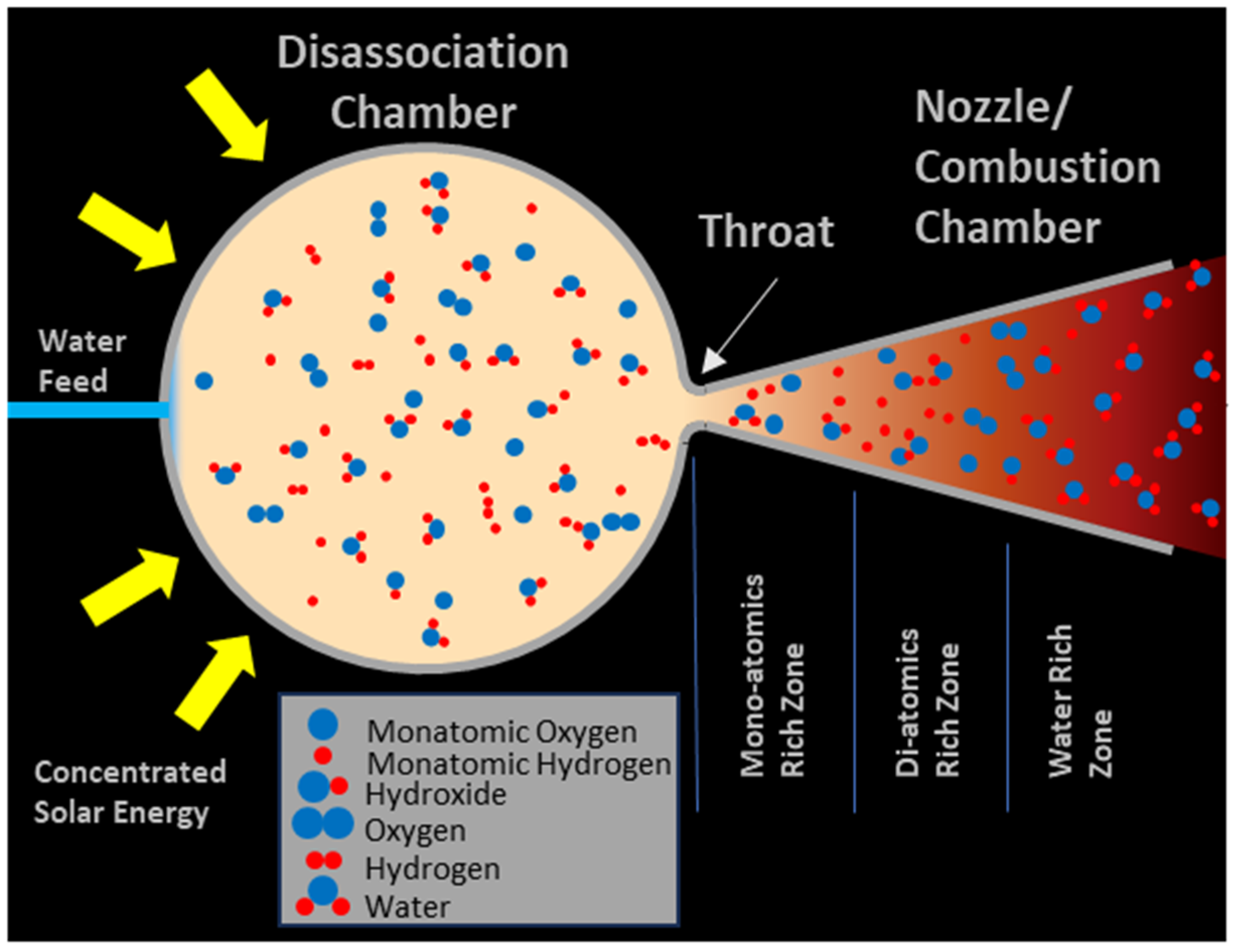
3. Method: Analysis of a Disassociated Steam System
3.1. Disassociative Steam Energy Calculations
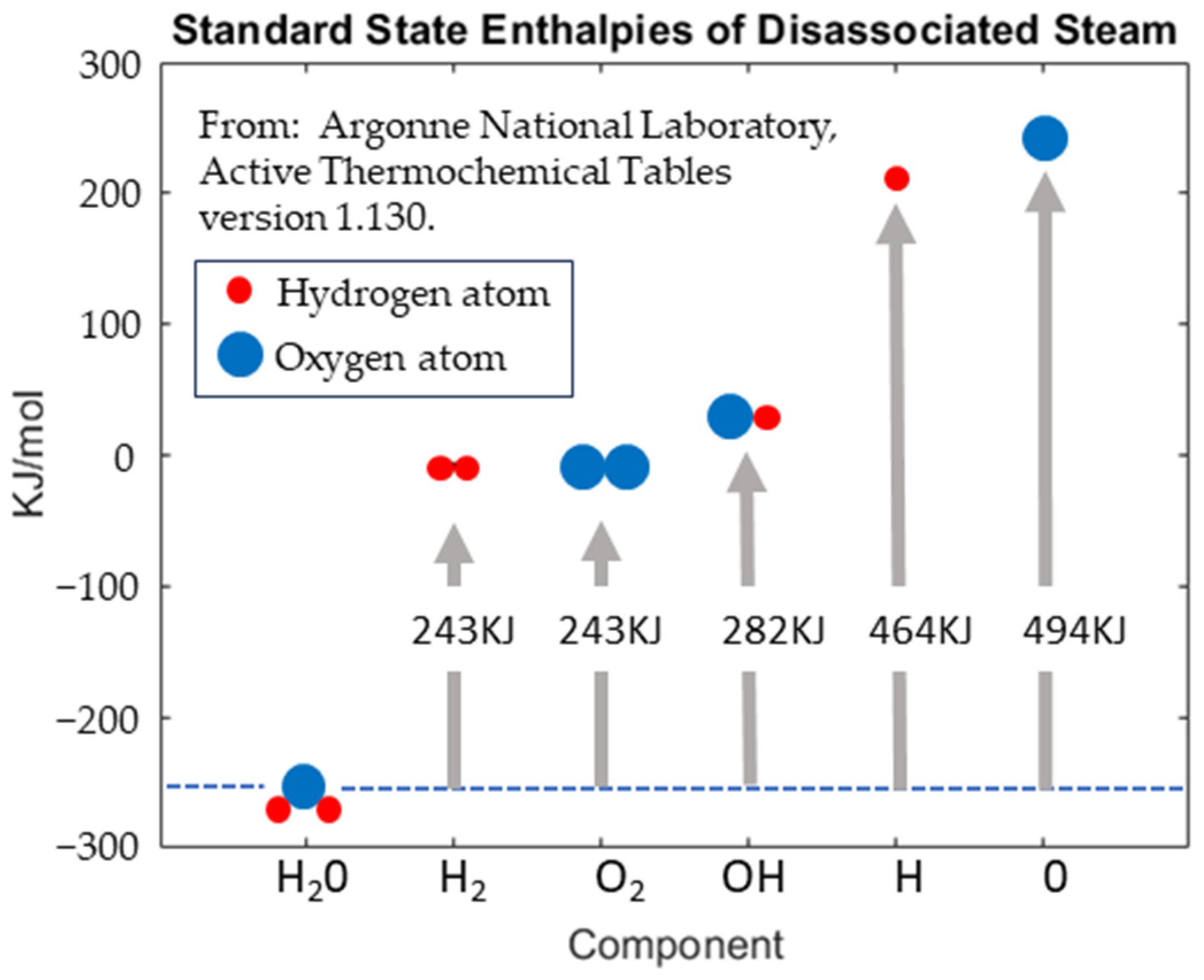
3.1.1. Heat of Formation of Components
3.1.2. Specific Heat Capacities for Each Component
3.1.3. Thermal Energy of Individual Components
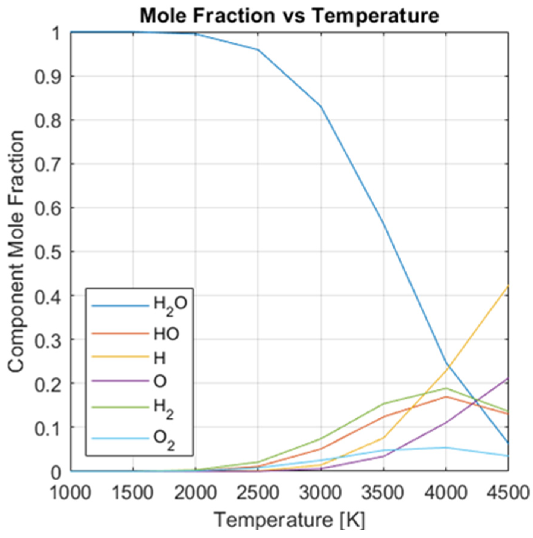
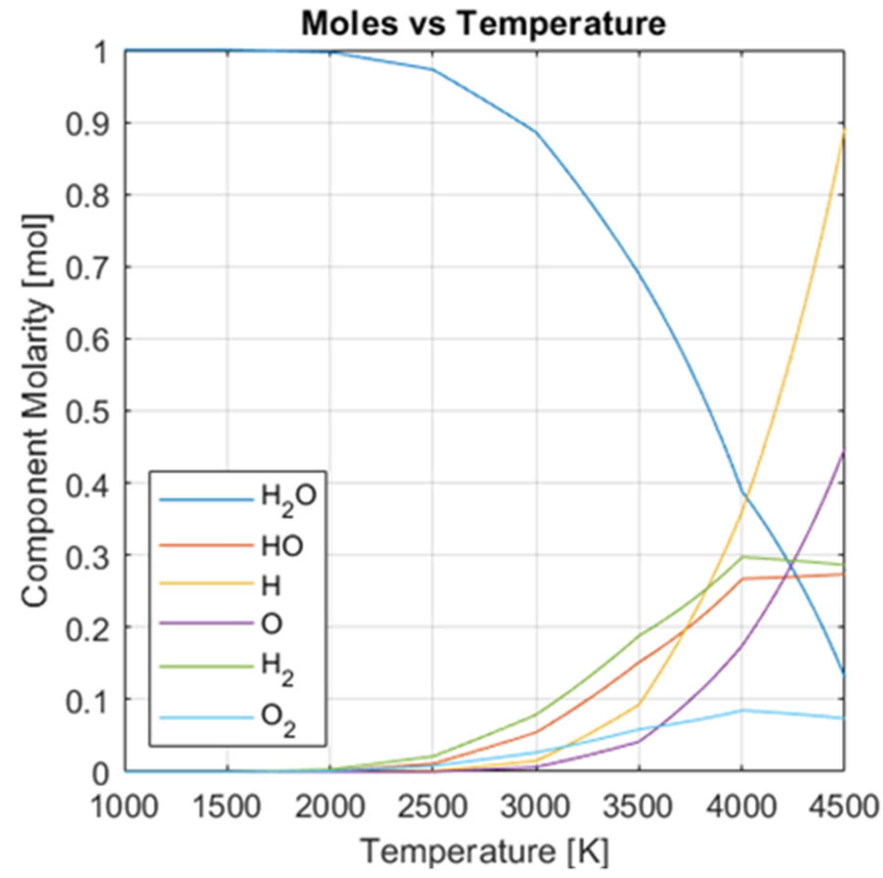
3.1.4. Component Dissociation as a Function of Temperature
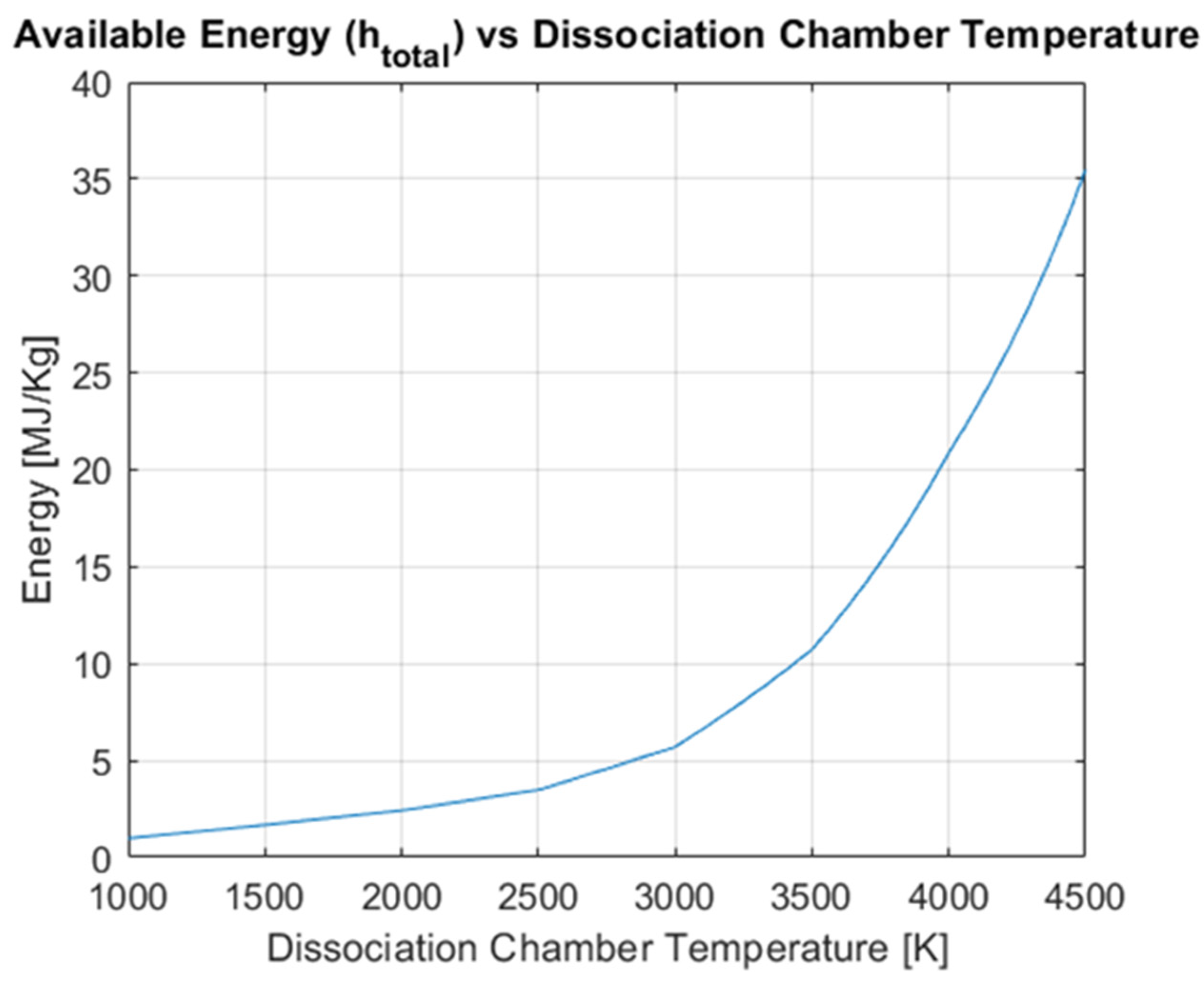
3.1.5. Total Thermal Energy as a Function of Temperature
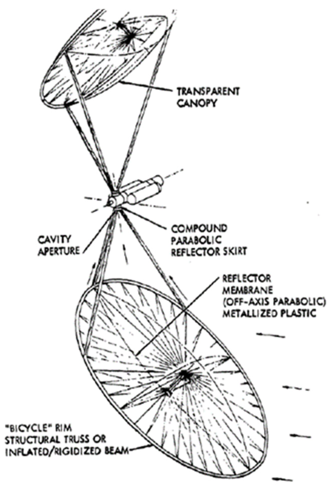
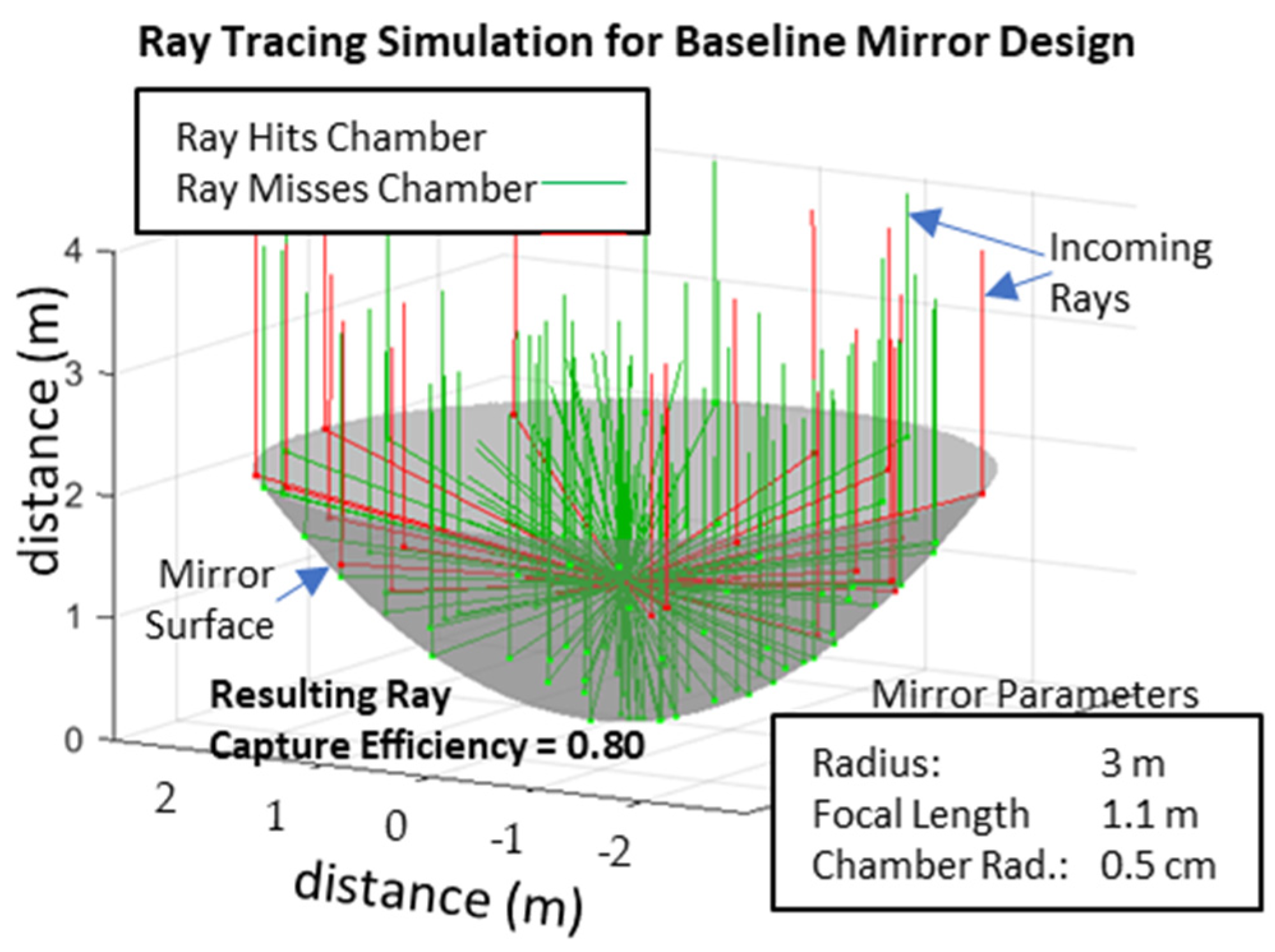
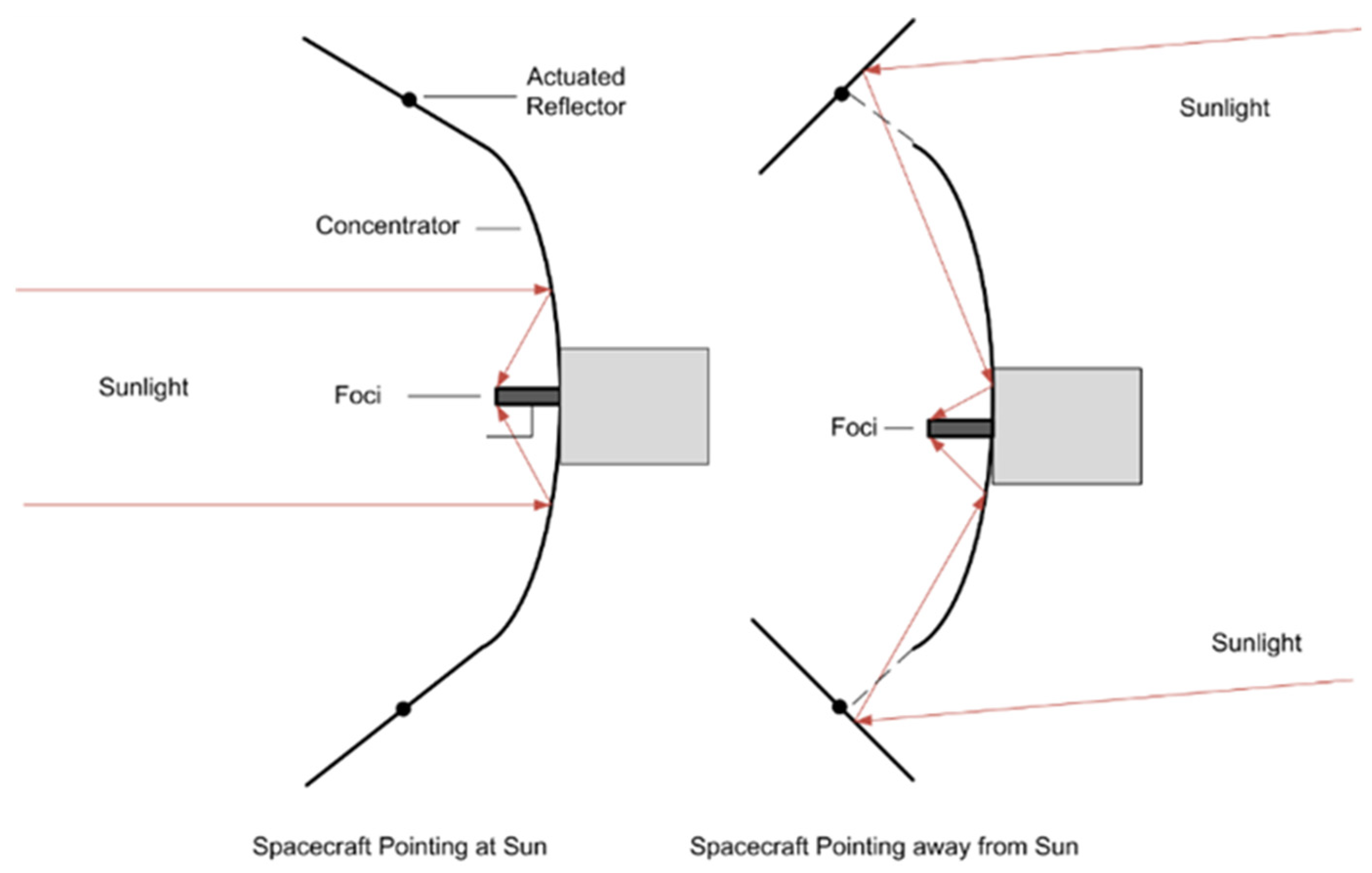
3.2. Parabolic Concentrator Optics
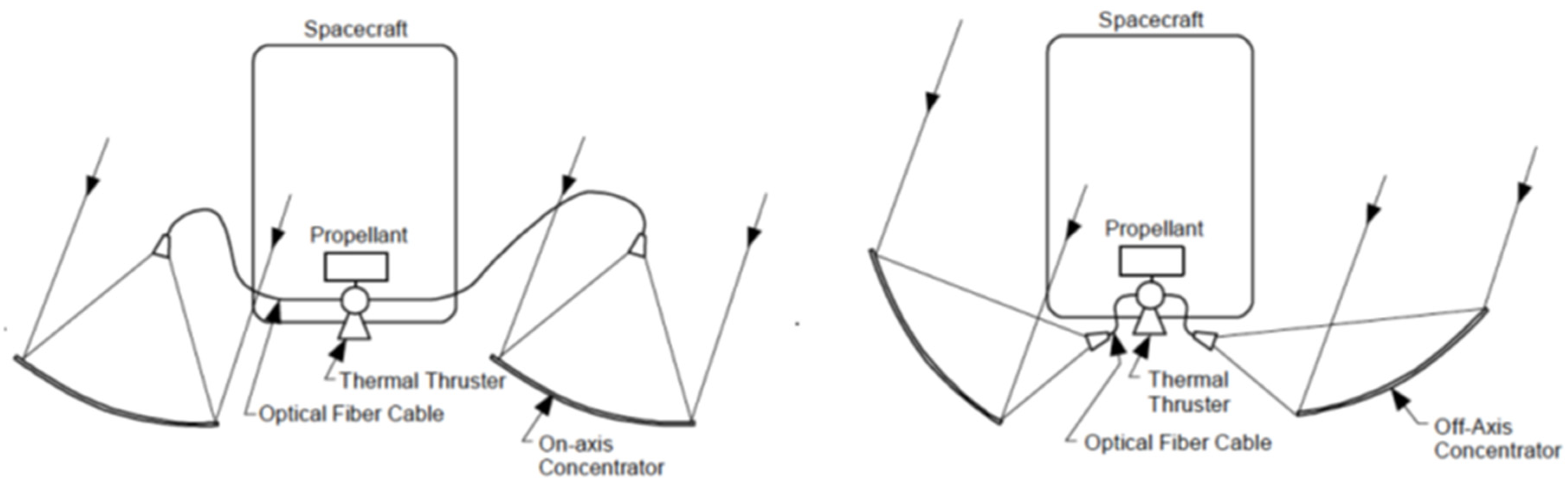
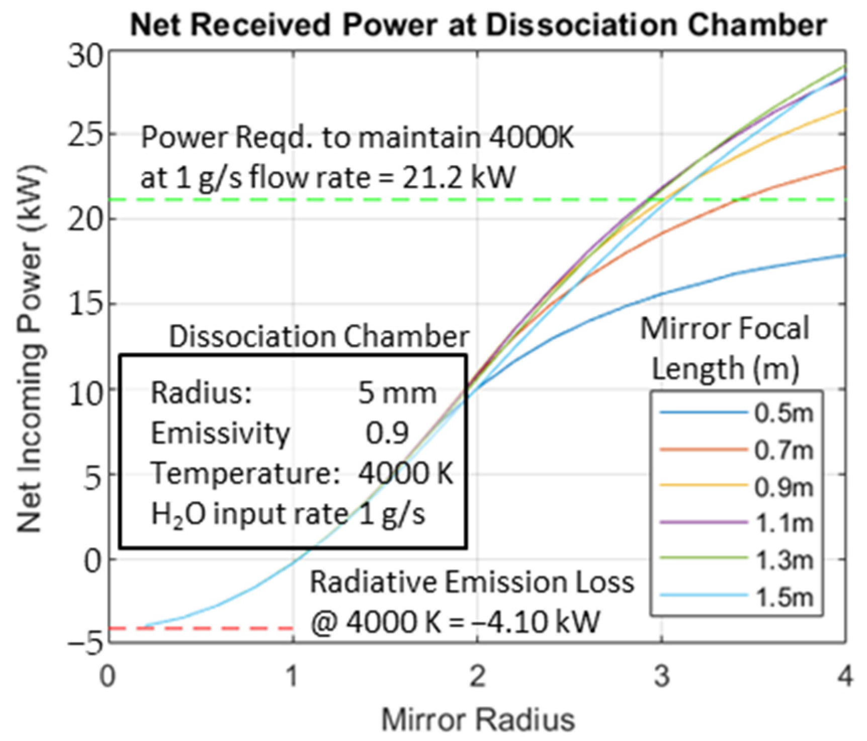
3.3. Parabolic Concentrator Configurations
4. Results
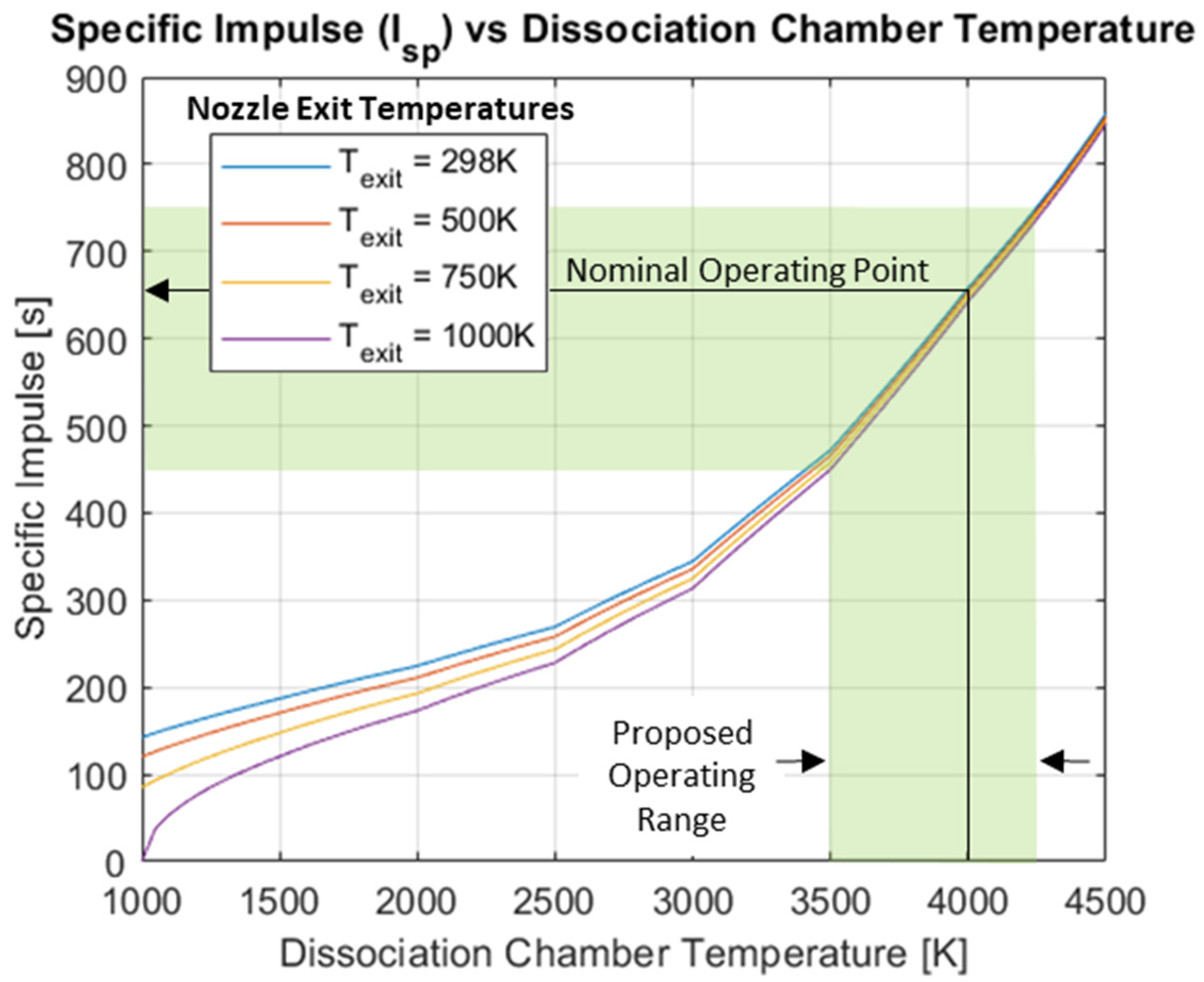
4.1. Specific Impulse Upper Limit Calculation
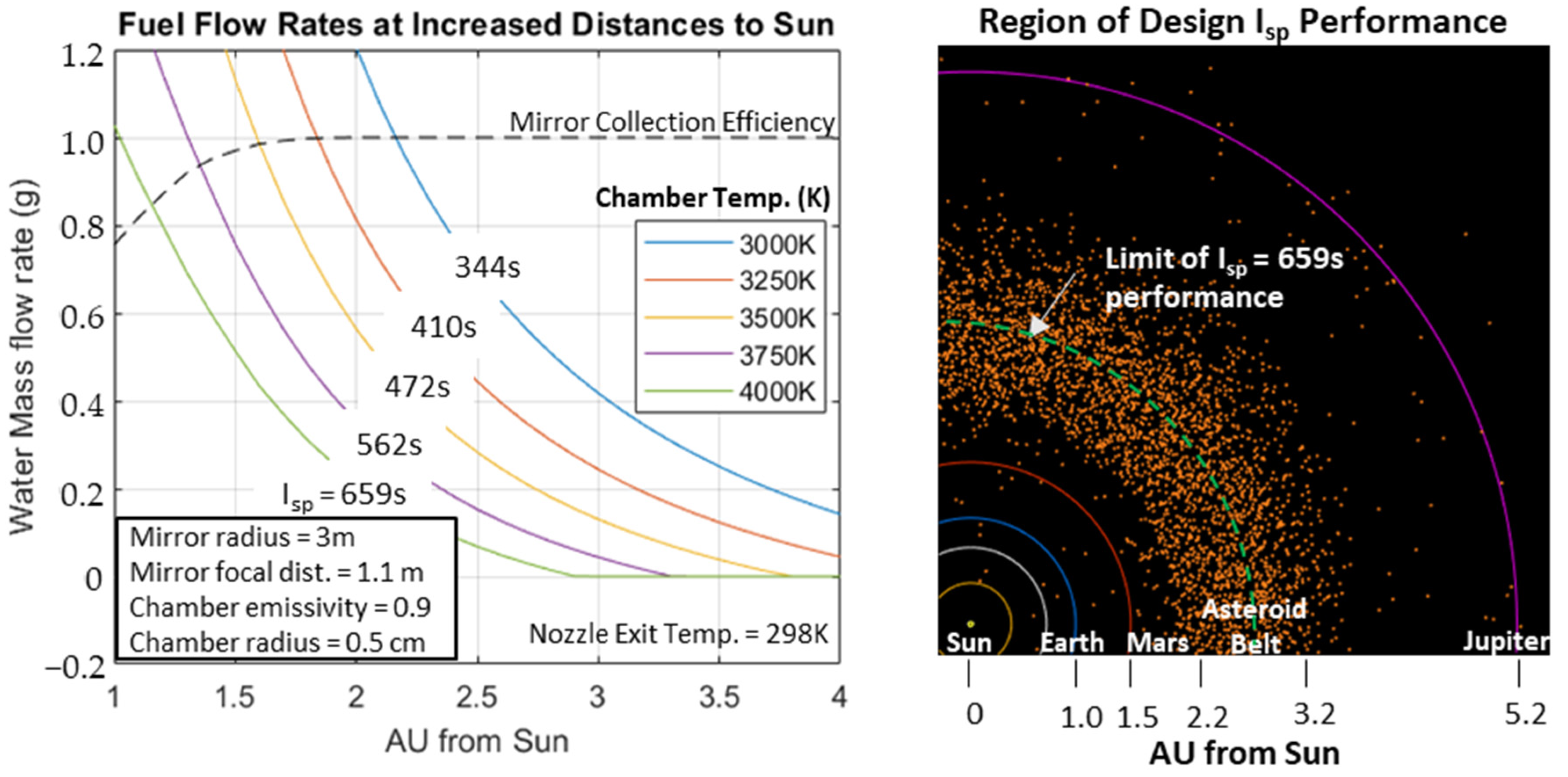
4.2. Propulsive Effectiveness at Increasing Distances from the Sun
4.3. Efficiency Comparison with an Electrolyzed Water System
5. Discussion
6. Conclusions
Author Contributions
Funding
Data Availability Statement
Acknowledgments
Conflicts of Interest
References
- Rafalskyi, D.; Martínez, J.M.; Habl, L.; Zorzoli Rossi, E.; Proynov, P.; Boré, A.; Baret, T.; Poyet, A.; Lafleur, T.; Dudin, S.; et al. In-orbit demonstration of an iodine electric propulsion system. Nature 2021, 599, 411–415. [Google Scholar] [CrossRef] [PubMed]
- Rabade, S.; Barba, N.; Garvie, L.; Thangavelautham, J. The Case for Solar Thermal Steam Propulsion System for Interplanetary Travel: Enabling Simplified ISRU Utilizing NEOs and Small Bodies. In Proceedings of the 67th International Astronautical Congress, Guadalajara, Mexico, 26–30 September 2016. [Google Scholar]
- Beck, P.; Eschrig, J.; Potin, S.; Prestgard, T.; Bonal, L.; Quirico, E.; Schmitt, B. Water abundance at the surface of C-complex main-belt asteroids. Icarus 2021, 357, 114125. [Google Scholar] [CrossRef]
- Rivkin, A.S.; Davies, J.K.; Johnson, J.R.; Ellison, S.L.; Trilling, D.E.; Brown, R.H.; Lebofsky, L.A. Hydrogen concentrations on C-class asteroids derived from remote sensing. Meteorit. Planet. Sci. 2003, 38, 1383–1398. [Google Scholar] [CrossRef]
- Cedillos-Barraza, O.; Manara, D.; Boboridis, K.; Watkins, T.; Grasso, S.; Jayaseelan, D.D.; Konings, R.J.M.; Reece, M.J.; Lee, W.E. Investigating the highest melting temperature materials: A laser melting study of the TaC-HfC system. Sci. Rep. 2016, 6, 37962. [Google Scholar] [CrossRef] [PubMed]
- Gabrielli, R.A.; Herdich, G. Review of Nuclear Thermal Propulsion Systems. Prog. Aerosp. Sci. 2015, 79, 92–113. [Google Scholar] [CrossRef]
- Cheah, K.H. Space Micropropulsion for Nanosatellites: Progress, Challenges and Future; Elsevier: Amsterdam, The Netherlands, 2022. [Google Scholar]
- Pothamsetti, R.; Thangavelautham, J. Photovoltaic Electrolysis Propulsion System for Interplanetary CubeSats. In Proceedings of the IEEE Aerospace Conference 2016, Big Sky, MT, USA, 5–12 March 2016. [Google Scholar]
- Brandhorst, H.; Rodiek, H.A.; O’Neill, M.J.; Eskenazi, M. Ultralight, Compact, Deployable, High Performance Solar Concentrator Array for Lunar Surface Power. In Proceedings of the 4th International Energy Conversion Engineering Conversion and Exhibit, San Diego, CA, USA, 26–29 June 2006. [Google Scholar]
- Wassom, S.R. Focus Control System for Solar Thermal Propulsion. In Proceedings of the International Adams User Conference, Rome, Italy, 15–17 November 2000. [Google Scholar]
- Glenn Safety Manual—Chapter 6: Hydrogen; NASA Document No.: GLP-QS-8715.1.6; NASA: Washington, DC, USA, 2021; p. 8.
- Ohta, T. (Ed.) Solar-Hydrogen Energy Systems: An Authoritative Review of Water-Splitting Systems by Solar Beam and Solar Heat: Hydrogen Production, Storage, and Utilisation; Pergamon Press: Oxford, UK, 1979. [Google Scholar]
- Available online: https://technology.nasa.gov/patent/LEW-TOPS-50 (accessed on 1 September 2023).
- Li, J.; Aierken, A.; Liu, Y.; Zhuang, Y.; Yang, X.; Mo, J.H.; Fan, R.K.; Chen, Q.Y.; Zhang, S.Y.; Huang, Y.M.; et al. A Brief Review of High Efficiency III-V Solar Cells for Space Application. Front. Phys. 2021, 8, 631925. [Google Scholar] [CrossRef]
- Tajmar, M. Advanced Space Propulsion Systems; Springer Nature: Berlin/Heidelberg, Germany, 2012; p. 76. [Google Scholar]
- Finseth, J.L. Rover Nuclear Rocket Engine Program: Overview of Rover Engine Tests; NASA: Washington, DC, USA, 1991. [Google Scholar]
- Hwang, M.; Rho, T.-S.; Lee, H.J. Conceptual design and performance analysis of water electrolysis propulsion system with catalytic igniter for CubeSats. Acta Astronaut. 2022, 200, 316–328. [Google Scholar] [CrossRef]
- Hodges, A.; Hoang, A.L.; Tsekouras, G.; Wagner, K.; Lee, C.-Y.; Swiegers, G.F.; Wallace, G.G. A high-performance capillary-fed electrolysis cell promises more cost-competitive renewable hydrogen. Nat. Commun. 2022, 13, 1304. [Google Scholar] [CrossRef] [PubMed]
- Bottke, W.; Cellino, A.; Paolicchi, P.; Binzel, R. Asteriods III; University of Arizona Press: Tuscon, AZ, USA, 2002. [Google Scholar]
- Thangavelautham, J. and Dubowsky, S. On the Catalytic Degradation in Fuel Cell Power Supplies for Long-Life Mobile Field Sensors. J. Fuel Cells Fundam. Syst. 2013, 13, 181–195. [Google Scholar] [CrossRef]
- Air Force Research Labs Report: The Place of Solar Thermal Rockets in Space, C.C. Selph. May 1981. Available online: https://apps.dtic.mil/sti/tr/pdf/ADA407602.pdf (accessed on 1 September 2023).
- Grossman, G.; Williams, G. Inflatable Concentrators for Space Propulsion and Dynamic Space Power. J. Sol. Energy Eng. 1990, 112, 229. [Google Scholar] [CrossRef]
- Jenkins, C. Gossamer Spacecraft: Membrane and Inflatable Structures Technology for Space Applications. Mech. Eng. 2001, 123, 82. [Google Scholar]
- O’Neill, M.J. Inflatable Fresnel Lens Solar Concentrator for Space Power. U.S. Patent 6,111,190, 29 August 2000. [Google Scholar]
- NASA SBIR Directorate: Deployable Collectors for Advanced Space Power and Propulsion Systems. Glenn Research Center. 1997. Available online: http://sbir.nasa.gov/SBIR/successes/ss/3-090text.html (accessed on 1 September 2023).
- Ethridge, F.G. Solar Rocket System Concept Analysis; Rockwell International Final Report, AFRPL-TR-79-79; Rockwell International, Space Systems Group: Downey, CA, USA, 1979. [Google Scholar]
- Nakamura, T.; Sullivan, D.; McClanahan, J.; Shoji, J.M.; Partch, R.; Quinn, S. Solar Thermal Propulsion for Small Spacecraft. In Proceedings of the 41st ASME/ASME/SAE/ASEE Joint Propulsion Conference, Tucson, AZ, USA, 10–13 July 2005. [Google Scholar]
- Fortini, A.; Tuffias, R.H. Design and Fabrication of Solar-Thermal Propulsion System. AIP Conf. Proc. 1996, 361, 1447. [Google Scholar]
- Chialvo, A.A.; Vlcek, L. Behaviour of rarified steam at very high temperature an orientation-averaged interaction potential approach towards its accurate description. Mol. Phys. 2019, 117, 3922–3940. [Google Scholar] [CrossRef]
- Betelin, V.B.; Shagaliev, R.M.; Aksenov, S.V.; Belyakov, I.M.; Deryuguin, Y.N.; Korchazhkin, D.A.; Kozelkov, A.S.; Nikitin, V.F.; Sarazov, A.V.; Zelenskiy, D.K. Mathematical simulation of hydrogen–oxygen combustion in rocket engines using LOGOS code. Acta Astronaut. 2014, 96, 53–64. [Google Scholar] [CrossRef]
- Das, L.M. Hydrogen-oxygen reaction mechanism and its implication to hydrogen engine combustion. Int. J. Hydrogen Energy 1996, 21, 703–715. [Google Scholar] [CrossRef]
- Braeuer, A. In Situ Spectroscopic Techniques at High Pressure; Elsevier: Amsterdam, The Netherlands, 2015; pp. 49–192. [Google Scholar]
- Argonne National Laboratory, Active Thermochemical Tables Version 1.130. Available online: https://atct.anl.gov/Thermochemical%20Data/version%201.130/index.php (accessed on 1 September 2023).
- Schürmann, M.; Schwinde, S.; Jobst, P.; Stenzel, O.; Wilbrandt, S.; Yulin, S.; Szeghalmi, A.; Bingel, A.; Munzert, P.; Kaiser, N. High-reflective coatings for ground and space based applications. In Proceedings of the International Conference on Space Optics, Tenerife, Spain, 7–10 October 2014. [Google Scholar]
- Varga, S.; Soares, J.; Lima, R.; Oliveira, A.C. On the selection of a turbulence model for the simulation of steam ejectors using CFD. Int. J. Low-Carbon Technol. 2017, 12, 233–243. [Google Scholar] [CrossRef]
- Goodger, E.M. Principles of Spaceflight Propulsion, 1st ed.; Pergamon Press: Oxford, UK, 1970; p. 15. [Google Scholar]


| H2O (g) | OH | H2 | O2 | H | O | |
|---|---|---|---|---|---|---|
| γ | 1.33 | 1.4 | 1.4 | 1.4 | 1.67 | 1.67 |
| Cv [J/(mol K)] | 25.18 | 20.76 | 20.76 | 20.76 | 12.4 | 12.4 |
| q(F) [kJ/mol] | −242 | 37.5 | 0 | 0 | 218 | 249 |
Disclaimer/Publisher’s Note: The statements, opinions and data contained in all publications are solely those of the individual author(s) and contributor(s) and not of MDPI and/or the editor(s). MDPI and/or the editor(s) disclaim responsibility for any injury to people or property resulting from any ideas, methods, instructions or products referred to in the content. |
© 2024 by the authors. Licensee MDPI, Basel, Switzerland. This article is an open access article distributed under the terms and conditions of the Creative Commons Attribution (CC BY) license (https://creativecommons.org/licenses/by/4.0/).
Share and Cite
Vance, L.; Espinoza, A.; Martinez Dominguez, J.; Rabade, S.; Liu, G.; Thangavelautham, J. A Solar Thermal Steam Propulsion System Using Disassociated Steam for Interplanetary Exploration. Aerospace 2024, 11, 84. https://doi.org/10.3390/aerospace11010084
Vance L, Espinoza A, Martinez Dominguez J, Rabade S, Liu G, Thangavelautham J. A Solar Thermal Steam Propulsion System Using Disassociated Steam for Interplanetary Exploration. Aerospace. 2024; 11(1):84. https://doi.org/10.3390/aerospace11010084
Chicago/Turabian StyleVance, Leonard, Agustin Espinoza, Jorge Martinez Dominguez, Salil Rabade, Gavin Liu, and Jekan Thangavelautham. 2024. "A Solar Thermal Steam Propulsion System Using Disassociated Steam for Interplanetary Exploration" Aerospace 11, no. 1: 84. https://doi.org/10.3390/aerospace11010084