1. Introduction
Traditional air transportation system is expected to transform into the Advanced Air Mobility (AAM) system, which is a more agile, flexible, and accessible air transportation system compared to the current one, offering an expansion of operations to the urban, sub-urban, and rural areas. Technological development, especially in Unmanned Aircraft Systems (UASs), is one of the key enablers for realizing the AAM concept and adopting it for daily usage. Yet, there are still many more challenges that have to be considered to fully benefit from the potential of such a system. These problems vary and include the following: the development of a smart city infrastructure, integration with the current air transportation system, technological developments, enhancing safety and creating a reliable system, designing use cases and relevant vehicle concepts, the development of proper traffic networks and structures, defining roles and responsibilities, setting proper standards and regulations, ensuring privacy, minimizing environmental impacts, and social adoption.
Current efforts in the AAM domain are towards defining a concept of operations (ConOps) that aims to prepare guidelines for such a new concept that will enable the future of air transportation. ConOps preparations include designing new business cases for AAM, assigning responsibilities to relevant stakeholders and setting their tasks, defining the base requirements for concept verification, setting up an operable traffic network structure and its standards regarding operations, defining services to be used, and outlining how to test and validate everything that is defined. The main purpose is to create a strong basis for achieving AAM. Various initiatives around the world are taken to prepare and validate these ConOps. In the United States, the Federal Aviation Administration (FAA), the National Aeronautics and Space Administration (NASA), and various industrial leaders have defined Urban Air Mobility (UAM) and UAS Traffic Management (UTM) concepts through envisioned operations and use cases [
1,
2]. Additional ConOps are available, for instance from NASA, which provides comprehensive information via passenger-carrying UAM [
3], and from Boeing and Wisk, which explores and expands on passenger-carrying uncrewed and autonomous UAM operations [
4]. Another plan about the secure integration of passenger and cargo aircraft into the current air transportation system under the UAM concept was released by Airbus [
5]. For the future air transportation in 2030, UK Research and Innovation established a vision and defined a roadmap for success in the United Kingdom (UK) [
6]. Similarly in Australia, Embraer and Airservices Australia prepared a joint ConOps on developing the UATM concept, and how to safely handle traffic and vertiports was discussed [
7]. Last but not least, ConOps for the European UTM systems (CORUS) project supported by the Single European Sky Air Traffic Management (ATM) Research Joint Undertaking (SESAR JU) has created an initial outline for UAM that introduces the U-space system and its enabling services and processes for future AAM [
8,
9], and these concepts were extended further and validated via demonstrations under the CORUS XUAM project [
10]. The U-space concept was first presented by SESAR JU, which aims to create a safe and efficient UTM system through novel services and particular requirements [
11].
Aside from defining an operable future AAM concept, some of the works focus on the previously mentioned individual problems to be overcome and aim to create a basis for an AAM infrastructure and realize such a concept. There are many exploratory research and demonstration projects underway, especially under SESAR JU. In terms of on-board systems to be used on AAM platforms, detect and avoid (DAA), communication navigation and surveillance (CNS), and autopilot systems have been explored through various projects, known as PercEvite [
12] and the advanced integrated remotely piloted aircraft system (RPAS) avionics safety suite (AIRPASS) [
13,
14]. Furthermore, technological European research for RPAS in ATM (TERRA) aims to design an architecture to operate in very low level (VLL) airspace safely by properly using ground-based technologies and infrastructure [
15]. The proposed architecture’s purpose is to enhance the utilization of U-space services. Furthermore, the “clear air situation for UASs” (CLASS) project creates a basis for surveillance technology usage in the U-space [
16] and the “drone critical communications” (DroC2om) project focuses on a new command and control data link architecture [
17]. U-space services are one of the core components for enabling the AAM. There are also research efforts on the development of such services. One of them is the “U-space initial services” (USIS) project, which aims to test U1 and U2 level services such as flight planning management, e-identification, tracking, and monitoring through live demonstrations [
18]. As a basis for services dealing with separation, the “defining the building basic blocks for a U-space separation management service” (BUBBLES) project defines a U-space separation management system to be used in strategic conflict resolution and traffic information [
19]. Moreover, the development and demonstration of new approaches for strategic and tactical level separation management are explained in projects such as “U-space separation in Europe” (USEPE) [
20], “a unified approach to airspace design and separation management for U-space” (Metropolis 2) [
21], and “tactical instrumental deconfliction and in-flight resolution” (TINDAIR) [
22]. Demand-capacity balancing by considering risk assessment and social adoption based on noise and visual pollution is dealt under the “demand and capacity optimization in U-space” (DACUS) project [
23]. Performances of some of the pre-flight and in-flight services through various use cases are tested in the “proving operations of drones with initial UTM” (PODIUM) project [
24]. Similarly, in the safe and flexible integration of advanced U-space services for medical air mobility (SAFIR-Med), various U-space services are tested, focusing on medical services with UAM [
25]. Another U2 service, geofence provision, is extensively covered in the “geofencing for safe and autonomous flight in Europe” (GEOSAFE) project, where the geofencing capabilities at different levels are tested through demos [
26]. Another project that shows the importance of one of the U-space services is the “ATM U-space Interface” (PJ34-W3 AURA), which sets the required guidelines and validates ATM and U-space integration by the help of a developed collaborative ATM/U-space interface, a U3 level U-space service [
27]. For the development of an information/data flow architecture, there are several projects, known as “the information management portal to enable the integration of unmanned systems” (IMPETUS) [
28] and the “drone European AIM study” (DREAMS) [
29]. These projects’ purpose is to define the required data flow between stakeholders and develop a proper information management system. Finally, the “integrated common altitude reference system for U-space” (ICARUS) project proposes a common altitude referencing system and new services related to that issue, such as a vertical conversion service, a vertical alert service, and a real time geographical information service [
30]. Security challenges of the U-space concept described in the “integrated security concept for drone operations” (SECOPS) project [
31].
Regarding integration, a demonstration was conducted under the “demonstration of multiple U-space suppliers” (DOMUS) project, where the federated architecture through multiple service providers along with U-space services such as strategic and tactical deconfliction was tested [
32]. In the “Gulf of Finland U-space” (GOF USPACE) project, a large scale demonstration aimed to show the interoperability between ATM and U-space together with micro-services provided by multiple U-space service providers (USSPs) through a flight information management system [
33]. There are many other projects, such as the “European UTM testbed for U-space” (EuroDRONE) [
34], the “d-flight internet of drones environment” (DIODE) [
35], Uspace4UAM [
36], and the “validation of U-space and its services by tests in urban and rural areas” (VUTURA) [
37], concerning testing of the U-space concept, safe integration, safe operations, and demonstrating U-space service capabilities focusing on various use cases.
There are also research efforts focusing on developing a simulation environment for testing and evaluating the envisioned systems for the AAM concept. One of them is NASA’s “flexible engine for fast-time evaluation of flight environments” (Fe
3), which is an evaluation tool for high-density low-altitude air traffic operations with a fast time simulation capability [
38]. The Fe
3 simulator enables a testing environment for UASs and manned aviation operations with weather uncertainty and communication, navigation, and sensor impacts, along with conflict resolution services. Boeing’s SkyWay simulator, which is an integrated ATM/UTM simulator for autonomous operations, is used especially for testing contingency management procedures in the Galician SkyWay project [
39,
40]. The SkyWay simulator also includes a detect-and-avoid feature for UASs to avoid collisions. Furthermore, a simulator named U-Sky was developed by Boeing, and it mainly focuses on the network perspective of AAM and provides an environment for testing advanced UTM services in a dense traffic environment and evaluating them through numerous metrics related to safety, efficiency, workload, and so forth [
41,
42]. Airbus UTM’s simulator USim provides a fast-time simulation environment for UAS traffic, including a set of UTM services focusing on demand-capacity balancing, strategic conflict resolution, strategic planning, and airspace assessment through metrics such as safety, efficiency, and fairness [
43]. Finally, Indra’s UTM ecosystem provide features such as real-time operation monitoring, data flow between stakeholders, and conflict detection and resolution [
44]. The considered UTM ecosystem consists of two parts: UTM Hub, which is used for the digital coordination of every element within the system, and UTM Connect, where the individual operations are connected to the UTM Hub.
The Air Mobility Urban-Large Experimental Demonstration (AMU-LED) is one of the very large demonstration (VLD) projects supported by SESAR JU [
45]. AMU-LED aims to provide an integration of UAM with traditional aviation, develop and test advanced U-space services and a system-wide contingency management concept that is defined, test both centralized and decentralized UAM architectures, and validate all defined concepts via real and simulated flight trials to pave the way for a future AAM concept. Finally, AMU-LED examines the social acceptance of the UAM concept during these demo flights. This paper focuses on the technology and infrastructure development efforts for testing and demonstrating the AAM concept in action by setting system requirements, building a co-simulation environment, deciding on the vehicles and simulators to be used, developing advanced U-space services, and defining use cases and scenarios. The main novelty of the developed infrastructure is the ability to accommodate real and simulated flights at the same time and analyze their interactions. The system provides real operational experience of AAM via real platforms and an AAM simulator that presents a realistic passenger experience for the air taxi concept, while providing scalability for such operations by including numerous simulated flights. Additionally, the development of automated advanced U-space services and their integration with the operations, by considering both pre-flight and in-flight stages and the coordination between those services, is an important contribution of this study.
The rest of the paper is organized as follows: In
Section 2, key concepts that are defined under AMU-LED ConOps for realizing the AAM concept and the system requirements for the testing infrastructure are explained. Details of the developed co-simulation environment, the used UASs and the AAM simulator, are detailed in
Section 3. In
Section 4, the outputs of the developed infrastructure and how the outputs are utilized for demonstration purposes are provided. Lastly,
Section 5 summarizes the main conclusions of this work.
2. Key Concepts and System Requirements
With the AAM concept, current air transportation will evolve by extending its operations through various use cases such as air cargo/meal deliveries, air taxis and shuttles, and surveillance flights at VLL. AMU-LED is one of the VLD projects for implementing and testing the AAM concept. AMU-LED’s purpose is to validate the defined ConOps, which includes new approaches for realizing the AAM concept. Different from the other projects, AMU-LED specifically proposes a new airspace structure where some types of vehicles and their flight levels are differentiated, proposes relevant possible U-space services, and outlines a system-wide contingency management concept. In this section, some of the key concepts that are defined under the AMU-LED ConOps are covered [
45].
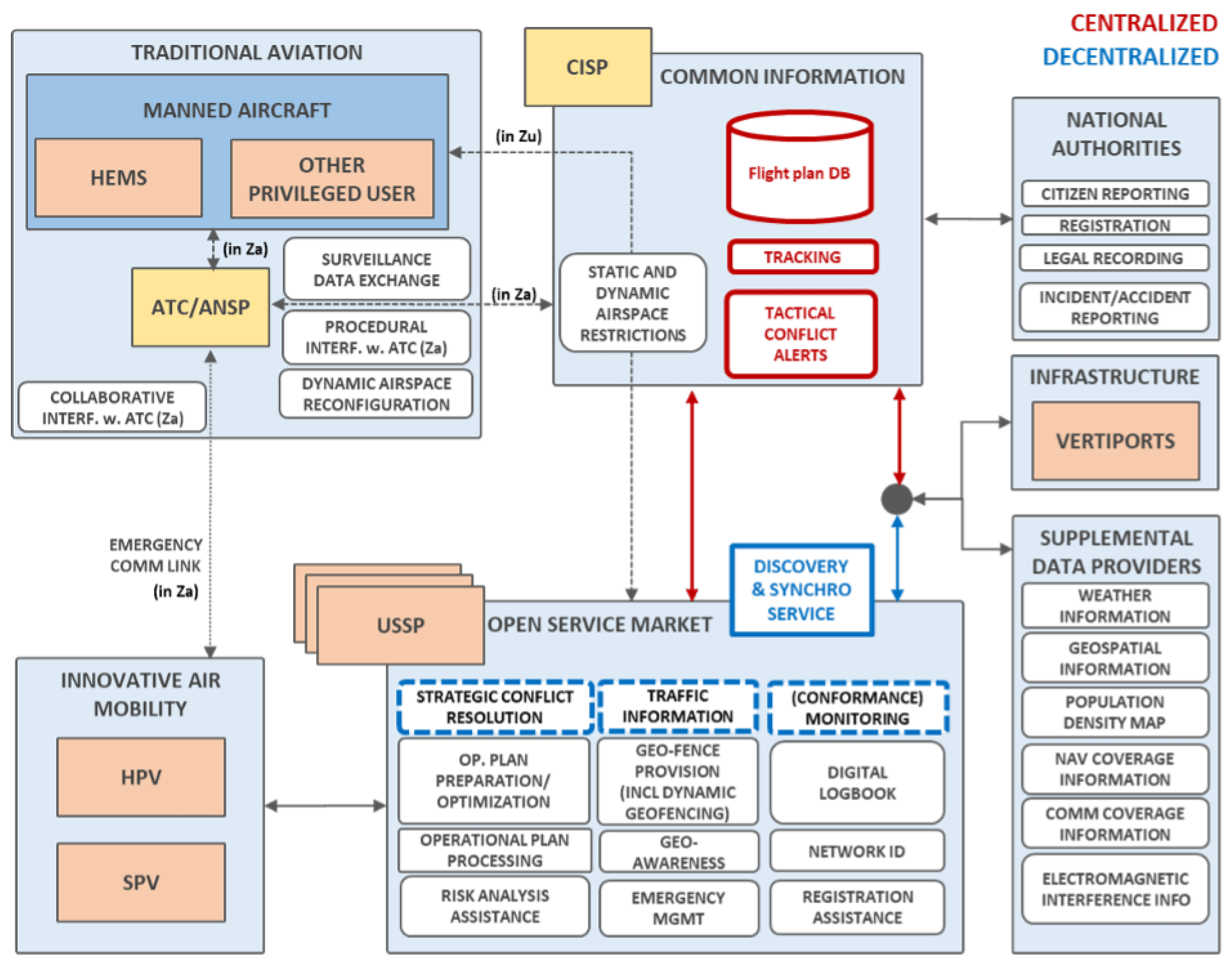
Figure 1 depicts the operational architecture that is adopted in the AMU-LED project. All the roles and responsibilities of each and every stakeholder and their interconnections are provided under that notional architecture for both centralized and decentralized approaches. According to it, traditional aviation consists of current air transportation system and its users. All the connection supposed to be through a common information service (CIS) provider (except in case of an emergency—there can be a direct connection between the air navigation service provider (ANSP) and operators), which mainly acts as a database and ensures data flow, especially for operational data. The considered data are provided to both the traditional aviation market and the open service market, which accommodates multiple USSPs. USSPs are responsible for providing various services, such as strategic conflict resolution, risk analysis assistance, conformance monitoring, contingency management, and registration assistance, to create a safe and efficient traffic environment. These services are provided to innovative air mobility users consisting of SPV and HPV flights. All AAM-related activities are supported and enhanced with supplementary data service providers (SDSPs) where the information related to weather, communication coverage, electromagnetic interference, and so forth are provided. An infrastructure block refers to the vertiports where the origin and destination points are represented. The information flow regarding vertiport availability or adverse conditions around a vertiport is ensured through a CIS provider for centralized architecture and USSPs for decentralized architecture. Finally, national authorities are responsible for registration, legal actions, and the reporting of any important case that directly provides input to CIS.
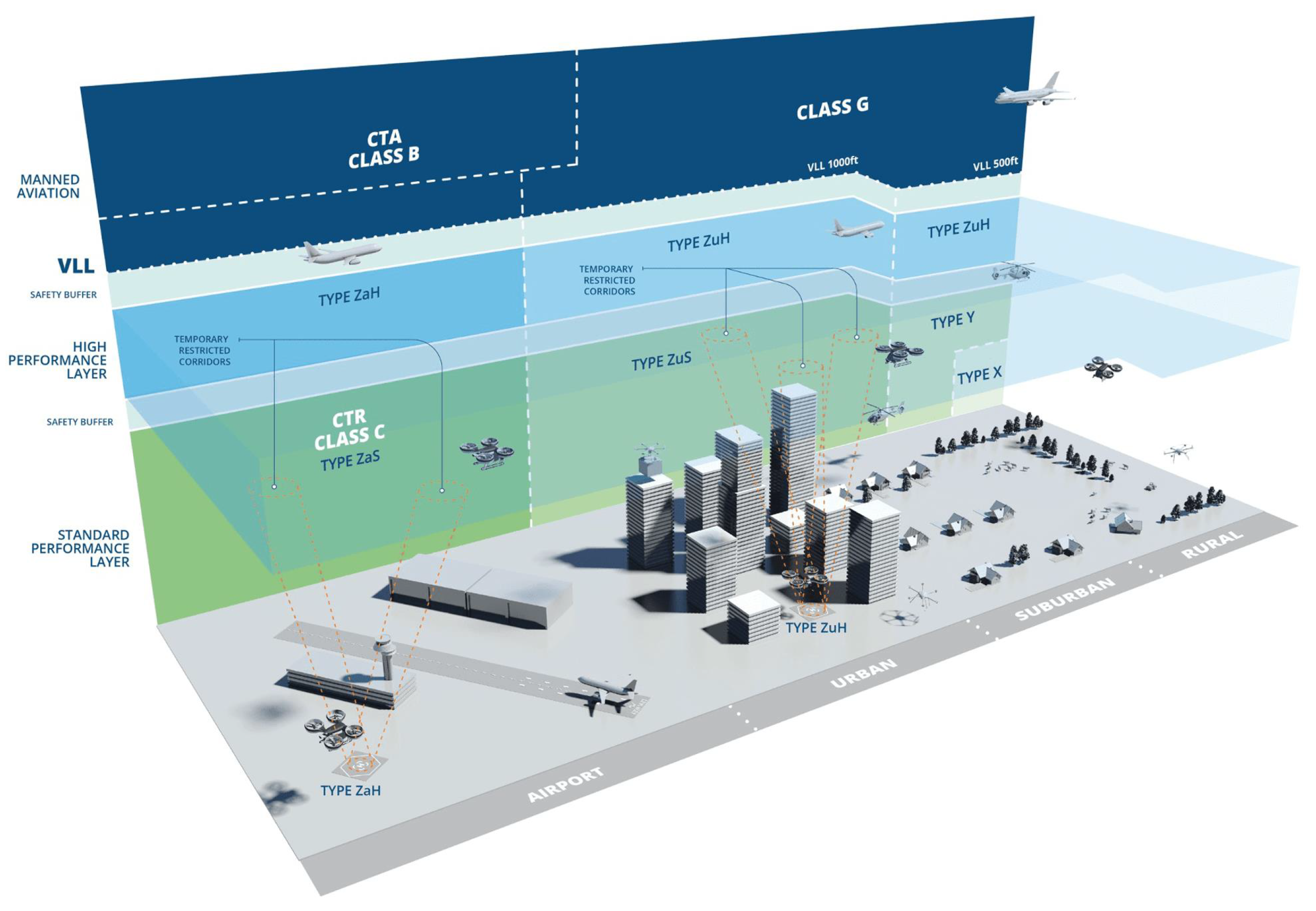
Categorization for vehicles is given as standard performing vehicles (SPVs), which refers to small UASs and high performing vehicles (HPVs) and includes air taxis and big cargo vehicles. This approach is valuable since it also refers to problems regarding operational activities of vehicles with different sizes. For instance, separation complexity between SPVs and HPVs has to be considered carefully since both have different dynamics, sizes, performances, and maneuver envelopes. This also applies to separation between HPVs and conventional manned aviation. Operational layers corresponding to SPVs and HPVs are defined as the standard performance layer (SPL) and the high performance layer (HPL), respectively [
45,
46]. The illustration of that layered airspace structure is as given in
Figure 2.
The layered airspace concept at VLL requires redesigning the existing U-space services or defining new services. Considered services have a wide range and are related to registration, identification and tracking, geoawareness and geofence provision, operational plan optimization, risk analysis assistance, flight authorization, conformance monitoring, strategic and tactical conflict resolution, contingency and emergency management, environment information, digital logbooks, and procedural and collaborative air traffic control (ATC) interfaces [
47]. Additionally, new HPV services are proposed, and these include vertiport flow and HPV corridor management, airspace and procedure design, dynamic capacity management, and advanced tactical conflict management, which considers performance envelopes of different types of vehicles for operation and separation management. The AMU-LED ConOps discusses what these services should look like, especially with the new structure that is proposed.
Last but not least, the AMU-LED ConOps introduces a system-wide contingency management concept where all of the stakeholders and their roles and responsibilities are considered [
48,
49]. A system-wide structure is built in a way where the possible base contingency scenarios can be observed by considering the roles and responsibilities of the stakeholders of the U-space system and the main contingency contributors. After obtaining the base scenarios, more complex cases can be analyzed by considering either the combination of the base scenarios or the increment in the level of complexity in a base scenario. Base contingency cases are obtained by simply matching the main contingency contributor with the individual tasks of each U-space partner. After that, strategies and action sets are discovered for every base contingency case, which leads to a generalizable comprehensive contingency management playbook. The defined action sets provide different options for solving contingency cases where different stakeholders can take responsibilities depending on their defined tasks.
Apart from the defined key concepts, system requirements are covered for validating these concepts and beyond and developing a testing infrastructure considering the simulation environment and real platforms. Requirements consist of having a proper contingency management protocol and executing it autonomously for simulated flights and manually for real flights, providing a proper interface for coordination with ATCs, being suitable for beyond visual line of sight (BVLOS) operations, accommodating different types of vehicles, managing vertiport traffic, rerouting, deconflicting, and/or prioritizing traffic efficiently in case it is required, and providing CNS properly.
3. Development of the Platforms
This section elaborates the platforms that are developed and used for the considered AAM flight testing and simulation infrastructure. The aim is to exhaustively cover the demonstration concerns of the AAM concept and to integrate it into daily life. Various points are considered, such as real UAM flights, UAM passenger aspect, high-density traffic with numerous use cases, the development and usage of U-space services, and integration considerations for achieving AAM. Platforms can be divided into three categories: the co-simulation environment, vehicles, and AAM simulator. The main purpose of creating a co-simulation environment is to have the ability to combine real flights with simulated ones, scale the AAM traffic, and simulate more complex traffic scenarios in terms of both the traffic size and interaction with other elements such as traditional aviation and UAM flights, which is expected with the future AAM concept. Considered vehicles are used to test the actual AAM system and its use cases properly. Lastly, the AAM simulator aims to ensure the complete flight experience of an AAM vehicle passenger since the actual flights of passenger-carrying AAM vehicles with passengers on board still need to be tested and explored.
3.1. The Co-Simulation Environment
AAM operations rely on high-level coordination and multiple services with different levels of autonomy for the safe and efficient integration of new platforms into the existing airspace system. Thus, a co-simulation environment is built to integrate and intercommunicate with all of the real and simulated elements of the demonstration. The co-simulation platform consists of three main parts: pre-flight services, a flight plan compiler, and in-flight services. Pre-flight services ensure that a new flight plan can be created easily and that the planned route is away from a geofence or a no-fly zone and has enough separation away from other airspace users by deconflicting at the strategic phase and generating flight routes based on risk analysis, dynamic capacity management, and mission priority. A flight plan compiler plays a bridge role to connect pre-flight services and in-flight services. In-flight services track vehicles to ensure they follow their assigned flight routes and update the relevant operators immediately in case of a non-conformance, contingency, or emergency situation, which also may require a tactical deconfliction during the flight.
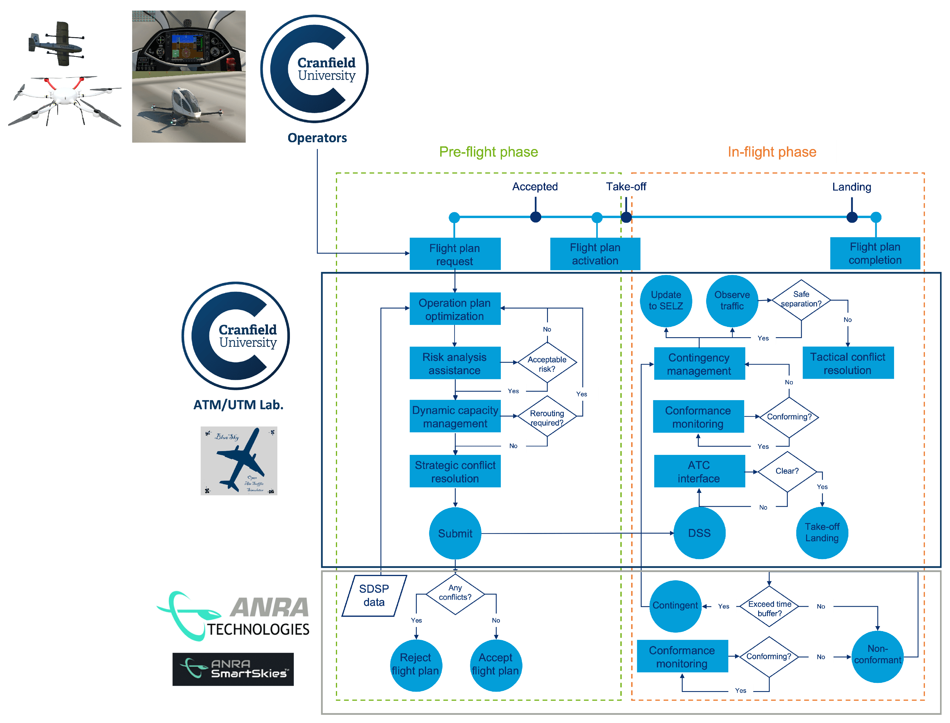
Figure 3 represents the framework of the co-simulation environment. To develop such a platform, the ANRA Technologies’ SmartSkies interface and the BlueSky simulator, which is used to develop the co-simulation environment, are integrated. The BlueSky simulator, which is an open air traffic simulator [
50], is used to test the autonomous U-space services developed.
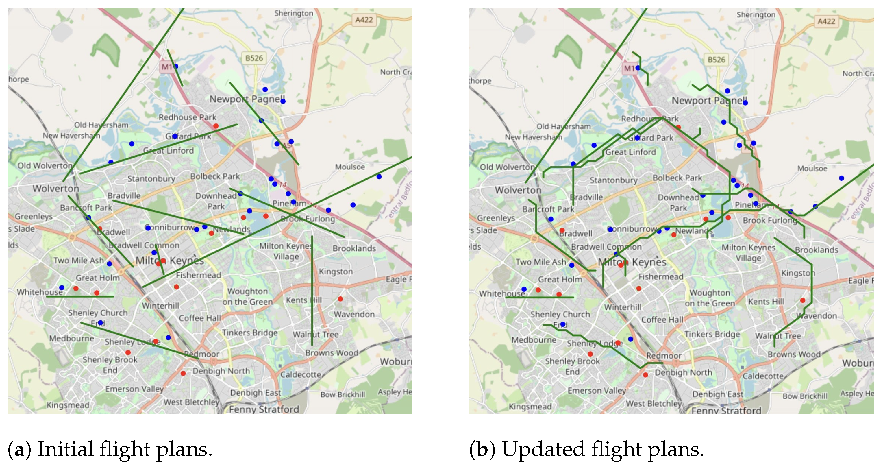
When an operator intends to conduct a flight, it first goes through the pre-flight services. The operation plan optimization service, which is integrated with the risk analysis assistance service, can assist in proposing a route that balances costs related to the safety and efficiency of the operation by also using the information provided by the SDSP. However, demand must also meet the capacity constraints, which is provided by the dynamic capacity management service. To achieve this, the flight plan is divided into waypoints that form a four-dimensional trajectory consisting of latitude, longitude, altitude, and time. The generated trajectory is then used to map the predicted traffic demand against the airspace capacity. The resulting trajectory is set as a flight plan and is presented in a specific format that includes the operator’s identity, performance volume, and waypoint information for the full trajectory. This flight plan is then evaluated by the strategic conflict resolution service, which checks if it intersects with any other accepted operations. If any conflict is observed, the flight plan is rejected, and the operator is notified. The operator is then required to revise the previous planning and propose a new flight plan that avoids the conflict. This process involves identifying an alternative route that ensures the safety of the operation and satisfies the demand-capacity balancing requirement. The revised flight plan is then again evaluated by the strategic conflict resolution service to ensure that it no longer intersects with any other active operation. This process may be repeated until a satisfactory flight plan is approved and confirmed.
Once flight plans are approved, the flight plan compiler steps in for flight plan processing internally, before using in-flight services. The integrated in-flight services are hosted in BlueSky simulator, which requires the stored flight plans to be converted into a useful datasets. This is achieved by using a compiler, which provides relevant simulation data as an output and connects the pre-flight and in-flight stages. There are several steps for the flight compiler module to work. First, the database for operations is parsed, and waypoints are extracted for each flight plan that will be used in conformance monitoring. The compiler then initializes the operator’s position and assigns the information regarding the operation’s schedule within the simulator. Finally, the operation data is recorded. These tasks are conducted in a loop with high frequency. This enables the system to respond quickly to changes and updates in flight plans. Overall, the compiler plays a critical role in converting flight plans into usable data for the in-flight services, enabling the system to provide real-time monitoring and analysis of flight operations.
As the planned take-off time approaches, the operation status is activated, and the tracking process begins. This status remains active as long as the flight conforms to the flight plan. However, if the flight deviates from the plan, the operator receives a non-conformance notification, and the status of the flight is updated in the discovery and synchronization service (DSS) server as non-conformant. If this status continues for a certain amount of time, it is changed to a contingent status in the DSS server. If a contingency event occurs, the on-board contingency manager block is activated for the contingent flight. In this case, the submitted flight plan is no longer valid, and surrounding traffic may be at risk of collision within its operational volume. The tactical conflict resolution service is then activated for the surrounding traffic near the contingent flight to provide a safe separation for flights that may be affected. When an operation is completed by reaching its destination, the operation is removed from the co-simulation environment.
3.2. Vehicles
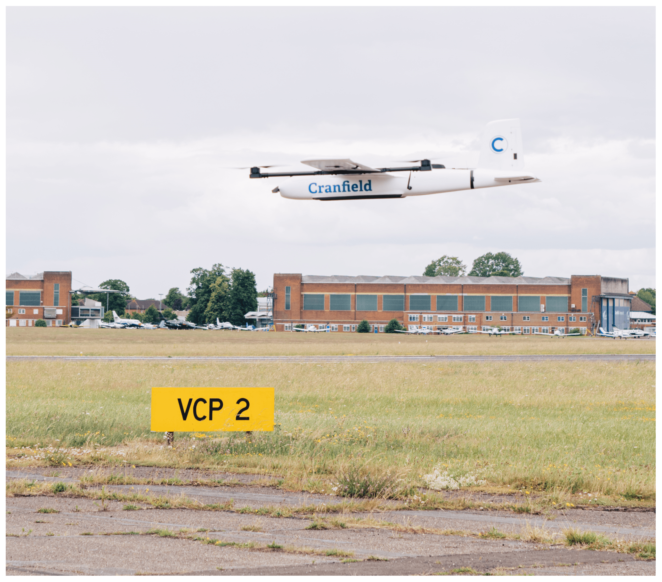
Two different vehicles are considered for representing the real flights. These are the Swift VTOL UAV and the Cranfield multicopter. These UAVs have high endurance and payload capacity with a customizable avionics architecture that allows operators to integrate and test different AAM use cases with fast iteration. The technical details of each UAV are given in the following section, with emphasis on their payload.
The Swift VTOL is a modified version of a MAKE FLY EASY 2.43 m wingspan VTOL aircraft. The specification of Swift VTOL is given in
Table 1. In addition to the standard avionics required for a fully autonomous mission, the Swift VTOL UAV is also fit with approved Electronic Conspicuity that provides ADS-B output. The uAvionix Ping 1090 Mode S module is used for ADS-B output. The UAV location is tracked throughout Cranfield ATC during the AMU-LED demonstration. The telemetry link between the UAV and Ground Control Station (GCS) is established to share the UAV location with USSP ANRA Technologies. A photo of the Swift VTOL UAV is provided in
Figure 4.
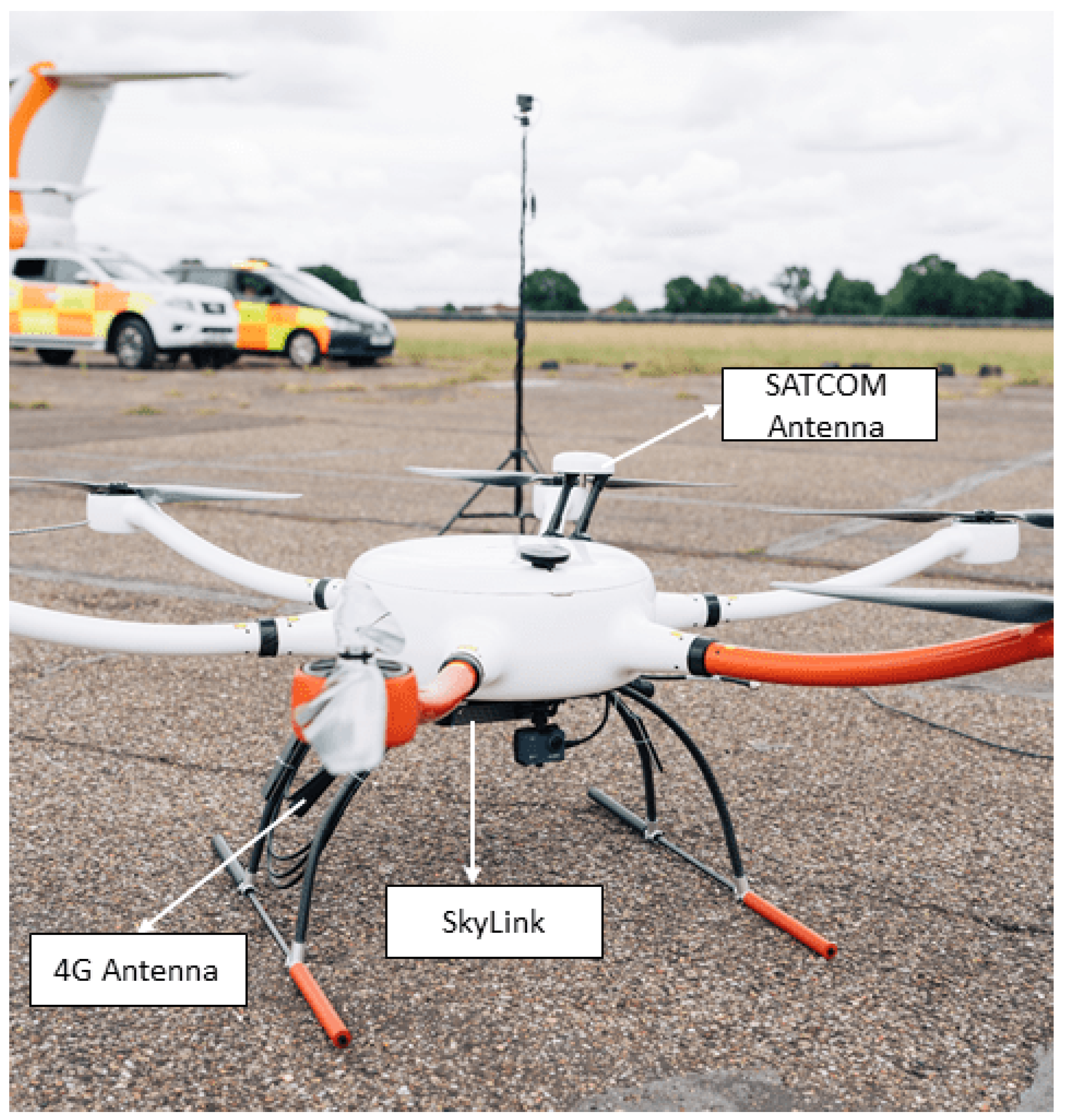
The Cranfield Multicopter is a modified version of the YANGDA YD6-1600L Heavy Lift Multicopter. The specifications of the Cranfield Multicopter are given in
Table 2. The Cranfield Multicopter is capable of being fully autonomous with a 5 kg payload capacity. With the collaboration of the Satellite Applications Catapult, the Multicopter UAV was equipped with a SATCOM and 4G modem called SkyLink, by the Blue Sky Network. This modem uses the Iridium satellite constellation and GSM/LTE network to provide an unlimited communication range. A photo of the Cranfield Multicopter with the SkyLink modem is given in
Figure 5.
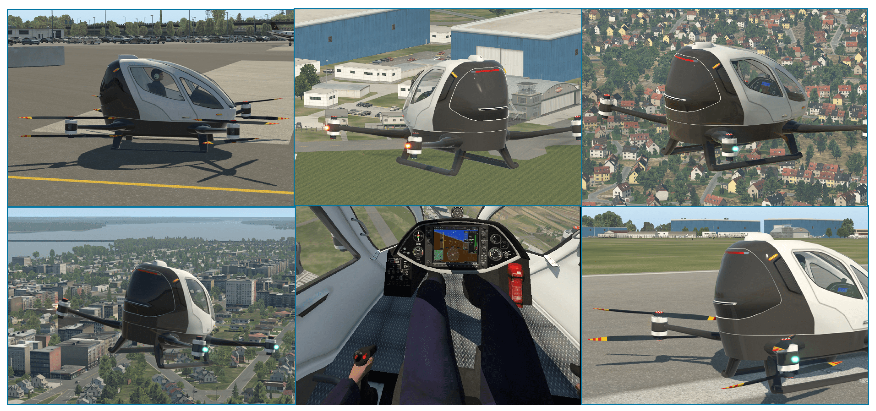
3.3. The AAM Simulator
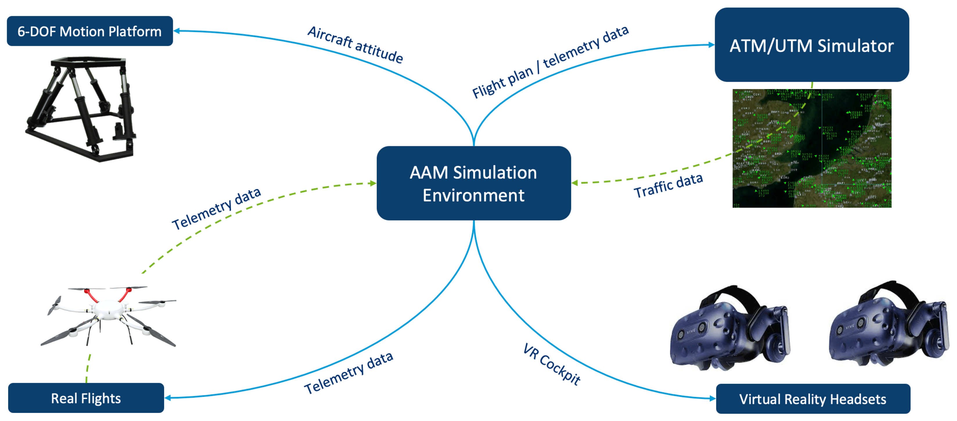
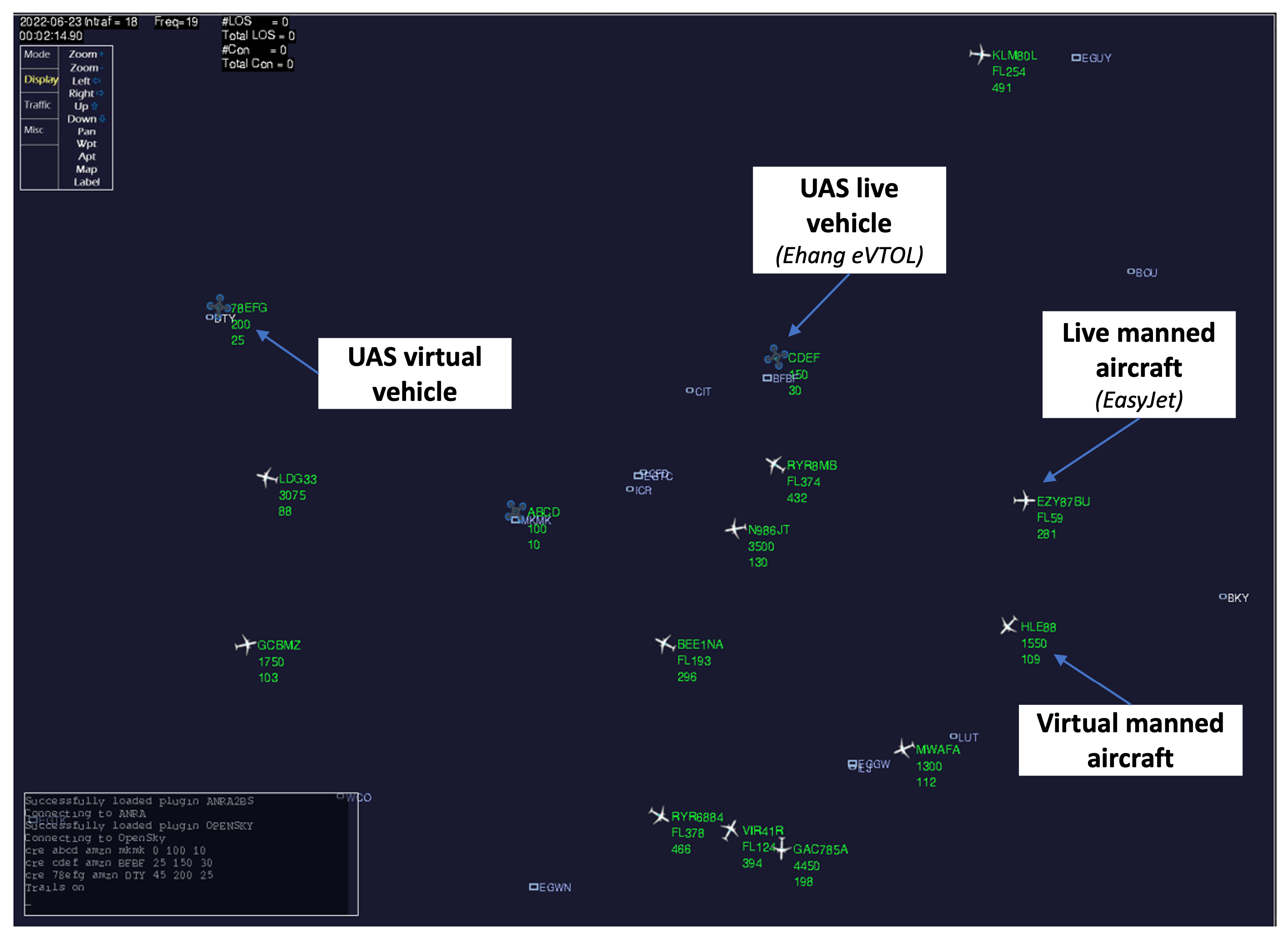
The AAM co-simulation environment represents a significant advancement in developing UAM systems. By integrating both actual UAS flights and simulated traffic within a single structure, it offers a comprehensive and realistic experience for passengers and operators alike. One of the key components of the AAM Simulation Environment is its six-degree-of-freedom motion platform for a passenger drone. This platform is designed to simulate the physical sensations of flying in a UAM vehicle, providing a truly immersive experience for passengers. Coupled with the virtual headset pair, passengers can feel as if they are flying through the city, experiencing the sights and sounds of urban air travel. The VR system is connected through the X-Plane 11 simulation platform, where the virtual urban environment is presented, vehicle dynamics are driven, and telemetry data with the surrounding real and simulated traffic are exchanged. The telemetry module is another crucial aspect of the AAM Simulation Environment. This module allows for the simulated vehicle’s telemetry to be transmitted to actual UASs, and vice versa. This means that operators can test and refine their UAS systems in a safe and controlled environment without the risks associated with real-world flight testing. The ATM/UTM simulator is yet another vital component of the AAM Simulation Environment. Using BlueSky [
50], all general aviation and UAS flights can be simulated, allowing operators to test their UAS systems in various scenarios and conditions. This simulator also provides a means of testing and refining ATM and UTM systems, which are essential components of any successful UAM network.
Figure 6 illustrates the system architecture, its elements, and data interchange.
Overall, the AAM co-simulation environment is a cutting-edge tool for developing and testing UAM systems. Combining actual UAS flights with simulated traffic offers a realistic and comprehensive experience for both passengers and operators while providing a safe and controlled environment for testing and refining UAS and ATM/UTM systems.
5. Conclusions
An AAM flight testing and simulation infrastructure was developed based on the key concepts and system requirements defined under the AMU-LED project. The purpose was to provide a testing baseline with every aspect of AAM and ease efforts on its full integration with everyday life. The developed infrastructure considers various perspectives of AAM stakeholders, such as the operator, the passenger, the USSP, and the ATC. The infrastructure consists of three main parts: the co-simulation environment, actual platforms, and the AAM simulator. The co-simulation environment assists USSPs in traffic monitoring and management by providing various pre-flight and in-flight services for UAM and the ability to track both the UAM and traditional aviation traffic. It also helps ATC in monitoring and intervening with traffic if it is needed via a collaborative display. Real platforms of the infrastructure, which are a Swift VTOL UAV and a Cranfield Multicopter, were used to demonstrate the actual flights of AAM traffic. Finally, the AAM simulator provides a full passenger experience of a future air taxi and allows for the simulation of an HPV in an AAM traffic environment. Each individual element, such as the flight plan update, collaborative interface, and AAM simulator, was tested, and the outputs were utilized in scenarios and flight plan definitions for an AAM demonstration.
Due to the safety concerns and limits of flight permissions, we were not able to test all of the advanced services that have been developed under the infrastructure on real flights. As a future improvement, we considered including a feature that also covers the AAM pilot/individual operator’s perspective, to be able to analyze the potential workload. We also want to improve the developed services, e.g., by including different protocols and extending the action sets for contingency management and tactical conflict resolution services. Additionally, we plan to test our flight testing and simulation infrastructure with different airspace configurations through various metrics.
Through the infrastructure, we were able to define different use cases and obtain relevant finalized flight plans with detailed trajectories at every flight phase and set departure times considering surrounding risks and capacity. Such a system also allows one to properly track the current traffic during operations and to interrupt in case of a disruptive condition via in-flight services. The considered system involves and provides communication between various elements such as real-time data from real platforms, simulated vehicles, and an actual AAM simulator with a VR feature.
After creating the baseline and infrastructure for demonstration activities, the next step is to validate the defined concepts under the AMU-LED project. All of the aforementioned platforms and developed services took part during an actual demo to showcase the future AAM concept. Further on, we will be providing details on the AMU-LED Cranfield demo, such as the collaboration of each stakeholder participating in the demo, technical aspects of the performed scenarios, public acceptance, data analysis, and recommendations for the future to enable AAM and benefit from its full potential.


 ,
, 


