1. Introduction
In future wars dominated by beyond-visual-range warfare, the stealth performance of aircraft will be critical [
1]. Relevant research indicates that the inlet and lip account for approximately 40% of the radar wave intensity scattering source within a 30° range in front of the fighter [
2,
3,
4]. Therefore, to enhance aircraft survivability, stealth design of the inlet must be included in addition to body stealth. For this reason, it is proposed to integrate an electromagnetic grille shield with a submerged inlet. The design of a submerged inlet, integrated into the missile body, has several advantages compared to traditional inlets, including reduced wind resistance and a decrease in the radar scattering area, thereby enhancing aircraft survivability [
5,
6]. However, the submerged inlet cannot make full use of the incoming flow stamping, leading to increased low-energy airflows entering the pipeline. This results in a suboptimal total pressure recovery coefficient and increased total pressure distortion for the submerged inlet. The integration of an electromagnetic grille shield would exacerbate these issues further.
As early as 1945, Frick et al. designed a NACA submerged inlet and conducted extensive experiments on it. The submerged inlet uses a long, inclined plate with a small inclination angle (about 7°) to introduce airflow into the inlet; however, the inlet’s small air intake and low total pressure recovery coefficient make it difficult for it to meet the main inlet requirements [
7,
8,
9,
10,
11,
12]. Subsequent work by Sun et al. studied the performance of the submerged inlet at high and low speeds with sideslip and positive and negative angles of attack. The surface parameters of the inlet were compared and studied. The results show that the side edge of the submerged inlet determines the strength of the entrainment vortex, the flow angle of the front lip determines the lateral pressure gradient of the inlet section, and the characteristic parameters of the rear lip profile adjust the distribution of the total pressure and the high- and low-pressure areas at the outlet of the inlet [
13].
In an effort to quantify the influence of the low-energy airflow in the boundary layer of the submerged inlet on intake performance, Xie et al. designed a submerged inlet splitter and used wind tunnel and numerical simulation methods to investigate. The results indicate that the total pressure recovery coefficient of the submerged inlet increased by 3.3% after the low-energy airflow was discharged by the shunt, and the circumferential distortion index decreased by 28.2% [
14]. Despite the efforts of researchers from several countries, submerged inlets still have some shortcomings, such as low total pressure recovery coefficients and high distortion rates [
15,
16,
17,
18,
19]. Consequently, researchers have shifted their research focus from inlet design to inlet flow control.
Flow control technology can be categorized into active flow control, passive flow control, and hybrid flow control, based on the need to inject additional momentum or energy [
20,
21,
22,
23,
24,
25,
26,
27,
28,
29]. Passive flow control technology includes blade vortex generators, convex ridge vortex generators, and others. Among these, blade vortex generators are the most widely used. Jirasek installed two groups of 64 micro-blade vortex generators on the UAV inlet to study the influence of the height of the blade vortex generator on the control effect through wind tunnel experiments. The results indicate that the control effect is optimal when the height is approximately 50% of the local boundary layer thickness, resulting in a 2% increase in the total pressure recovery coefficient of the inlet and a nearly 50% decrease in the distortion index [
30]. Vane-type vortex generators are small in size and are often proportional to the thickness of the local boundary layer. Blade-type vortex generators generate a single small streamwise vortex, making blade-type vortex generator arrays a common means for achieving flow control. Gissen et al. studied a vortex generator array through the DOE method and established mapping between the array parameters and inlet performance parameters via the response surface method. The results indicate that control effects are best when the blade height is approximately 30% of the boundary layer thickness and the relative flow direction deflection of the blade is 13° [
31]. To prevent the boundary layer on the surface of the missile body from entering the inlet, Saheby et al. arranged a convex ridge vortex generator in the inlet and studied the structure of the vortex and boundary layer transition by numerical simulation. The results show that the convex ridge vortex generator can significantly improve the efficiency of the inlet in subsonic flight; however, since the convex ridge vortex generator is situated on the surface of the missile body, it is sensitive to the angle of the airflow passing through the convex ridge, reducing the flow control efficiency significantly at large sideslip angles [
32]. Sun et al. designed a bumped vortex generator for the submerged inlet and verified it through wind tunnel experiments. The results indicate that the upstream missile body’s boundary layer is effectively pushed away from the inlet entrance using the bubbling vortex generator. This improves the inlet flow quality and performance of the submerged inlet. At a free-flow Mach number of 0.73, the total pressure recovery coefficient of the submerged inlet can be increased by 3.7% [
33,
34].
Active flow control technology includes jet vortex generators, boundary layer blowing and suction, and more. Neal et al. conducted a comparative analysis of the layout forms of micro-jets, including the circumferential layout, the axial layout of the bottom plate, the V-shaped layout of the bottom plate, and other schemes. The results indicate that all micro-jets layouts effectively reduce the distortion index of the inlet; however, the circumferential and V-shaped angle of about 80° performs better in terms of the control effect [
35]. Yadav et al. studied the Y-shaped double inlet and compared the effect of a slotted synthetic jet and a row of four circular synthetic jets on improving the aerodynamic performance of the aircraft inlet. The slotted synthetic jet has greater control force because the vortex generated by the slotted synthetic jet is distributed along the spanwise direction, making the ejected airflow’s mass and vorticity easier to mix with the mainstream [
36]. Cheng et al. proposed a submerged inlet flow field control scheme based on surface blowing and suction of the missile body. CFD numerical simulation was used to explore the influence of this flow control scheme on the inlet’s performance. The research results indicate that the control scheme based on the surface blowing and suction of the missile body improves the intake performance to a certain extent, but requires additional airflow sources. Usually, high-pressure airflow is extracted from the compressor directly, meaning the blowing flow rate cannot be too high; otherwise, it will impact the engine performance [
37,
38].
While both active and passive flow control technologies can improve the intake performance of submerged inlets to a certain extent, each approach has limitations. While passive flow control does not require additional energy, its effectiveness can be limited in some flight conditions. Meanwhile, active flow control strategies can adapt flexibly to changing flight conditions, but additional energy injection is required. A novel method that differs from conventional active and passive flow control is proposed in this paper. To address the shortcomings of the low total pressure recovery coefficient and high total pressure distortion indices of submerged inlets with grilles, a front auxiliary inlet was creatively designed. The feasibility of the scheme was verified using CFD numerical simulation technology, followed by an exploration of the influence of the relevant parameters of the front auxiliary inlet on intake performance. Sensitivity analyses of the related parameters are provided.
2. Front Auxiliary Inlet Design
While the stealth characteristics of submerged inlets are generally favorable, their larger cavity structures still exhibit discernible electromagnetic reflection characteristics [
1]. Electromagnetic grille shielding technology can help scatter the electromagnetic wave in the grille, reflecting most of the energy of the incident electromagnetic wave in a direction undetectable by radar. It can also force the electromagnetic wave entering the inlet to reflect multiple times between the grille and the cavity, reducing the energy of the electromagnetic wave and increasing its scattering degree in the cavity, thereby further reducing the intensity of the echo. Given the modern aircraft’s prioritization of stealth performance and the importance of this feature, greater emphasis is placed on stealth design during the design process; therefore, the application of electromagnetic grille shielding technology to submerged inlets was considered.
2.1. Electromagnetic Shielding Grille Design
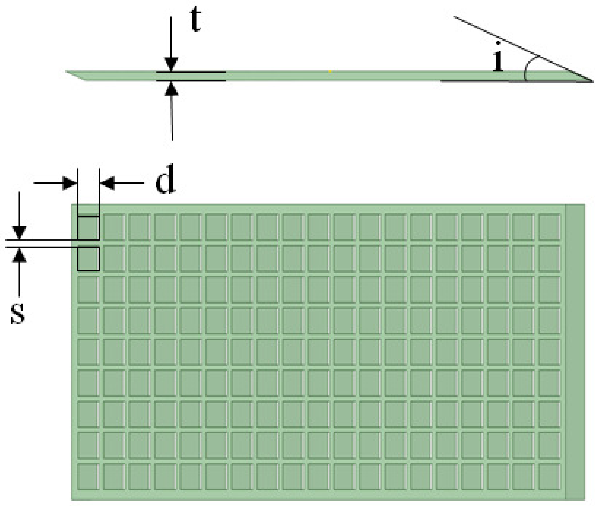
The main design parameters of electromagnetic shielding grille include the grille diversion angle (
i), grille thickness (
t), grille hole profile shape, grille hole characteristic length (
d), adjacent grille hole spacing (
s), porosity (
p), and more, as shown in
Figure 1. Electromagnetic grille shielding technology is a mature stealth technology and has been widely verified in many advanced aircraft designs.
Table 1 provides the design parameters directly; therefore, we will not discuss the design process further.
2.2. Flow Characteristics of Submerged Inlet
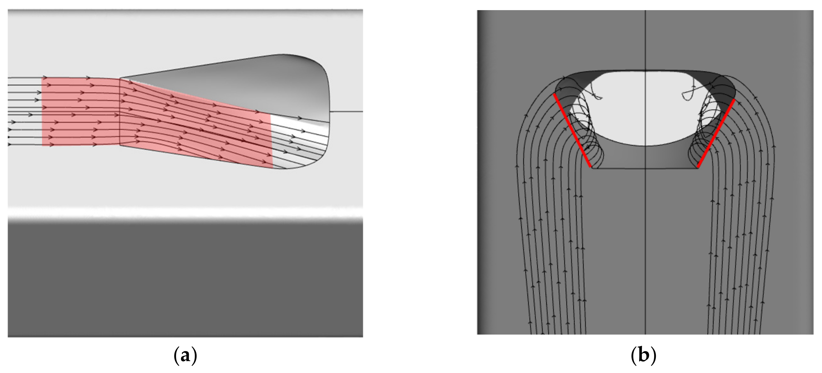
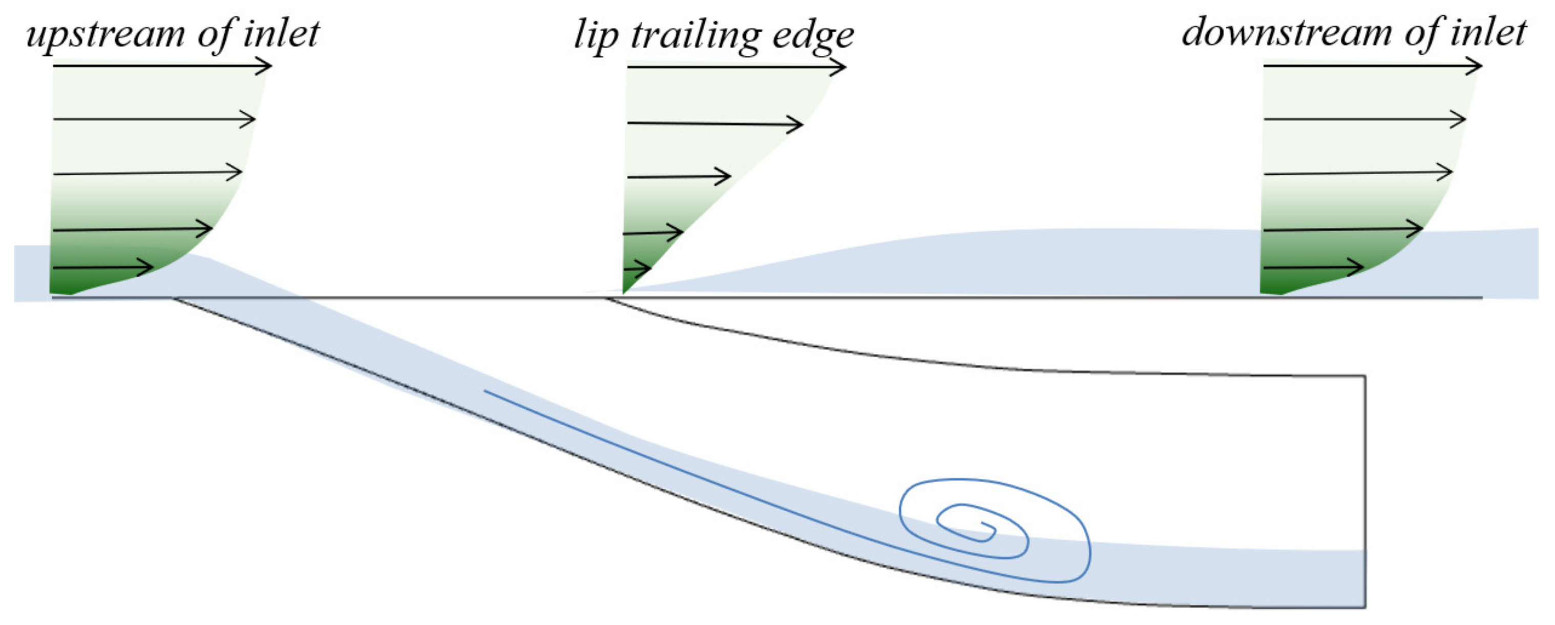
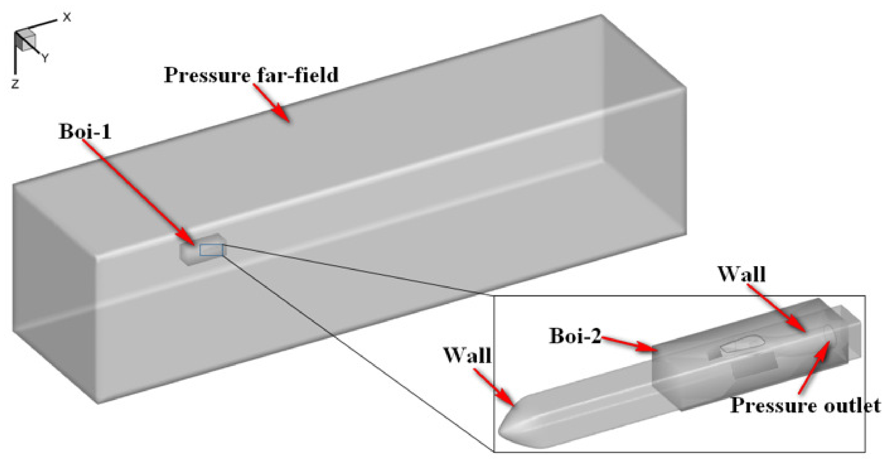
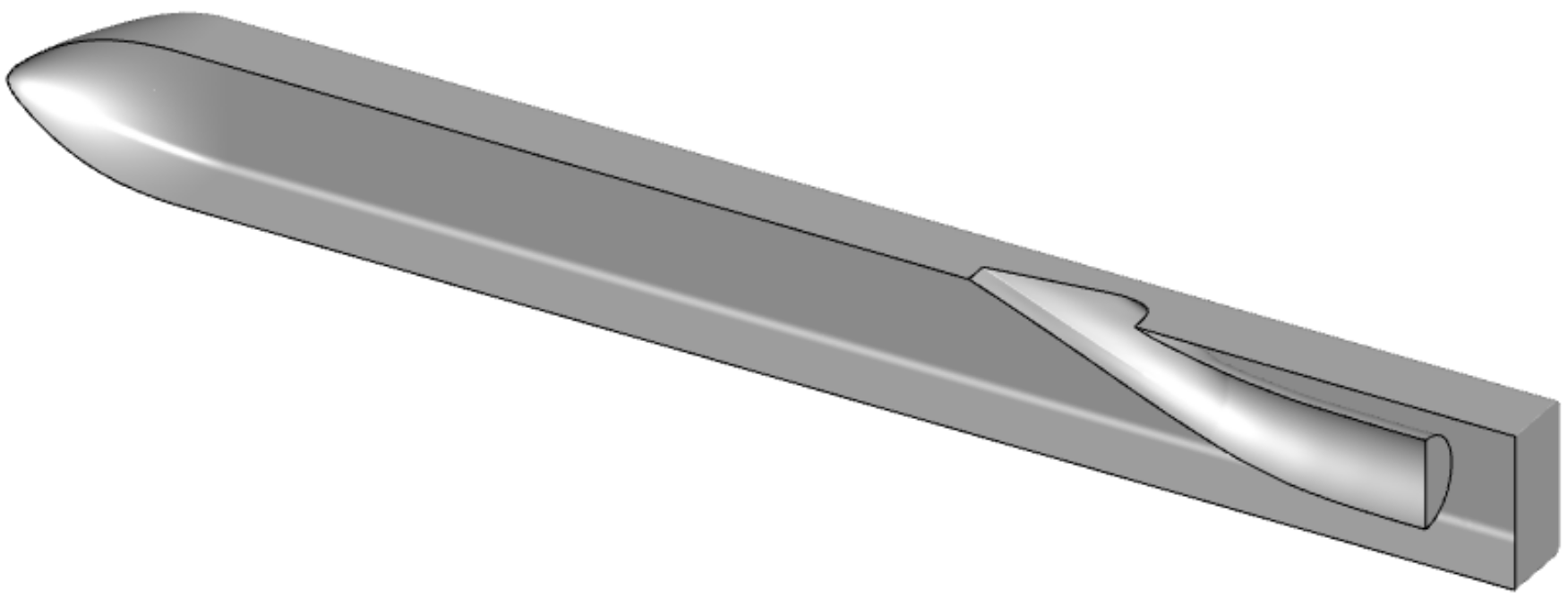
To improve the intake efficiency of the submerged inlet, it is essential to understand the intake mechanism. The submerged inlet primarily relies on the pressure gradient perpendicular to the incoming flow direction at the front lip and the entrainment vortex generated by the side edge to drive the external airflow into the inlet (
Figure 2). The main factor affecting the inlet’s performance is that the entrance of inlet on the body surface is located in the boundary layer near the missile body. As a result, low-energy airflow inevitably flows into the inlet, inducing large-scale separation vortices and large inlet outlet total pressure distortion [
39] (
Figure 3).
When the submerged inlet is covered with a grille, the effective area of the inlet opening is first reduced. Secondly, the inlet can no longer rely on the pressure gradient perpendicular to the incoming flow direction at the front lip and the entrainment vortex generated by the side edge to drive the external airflow into the inlet. Finally, when the airflow flows into the grille hole, it shrinks and its velocity increases. Upon exiting the grille, the airflow expands and the velocity decreases. This inflow and outflow process results in “impact loss”, which further reduces the energy of the airflow flowing into the inlet therefore, efficient flow control methods are necessary when combining electromagnetic grille shielding technology with the submerged inlet.
2.3. Design Idea of Front Auxiliary Inlet
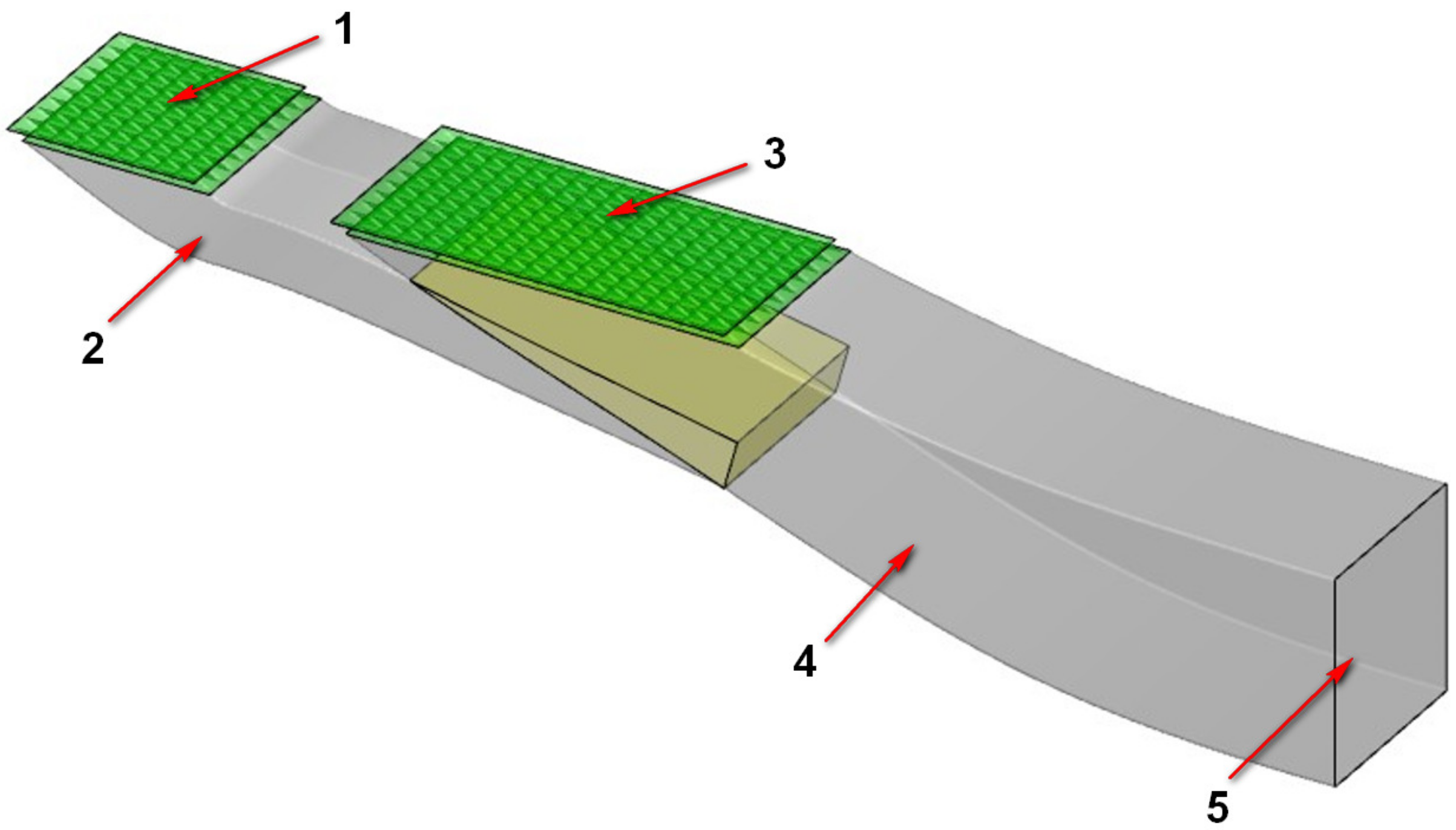
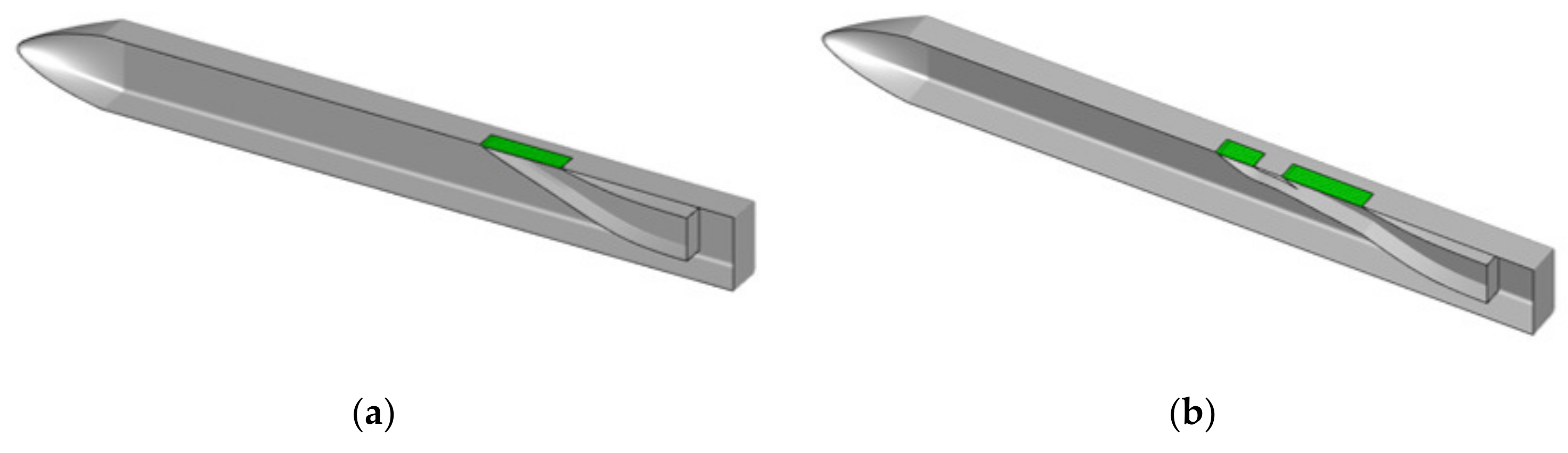
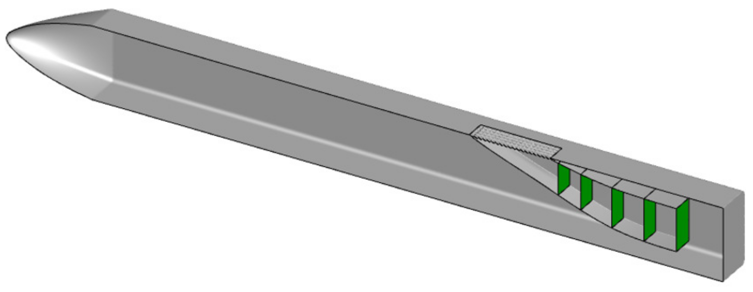
The limited space for arranging the inlet in an aircraft is constrained by the internal structure, making it crucial to maximize the intake efficiency. This can be achieved by (1) reducing or eliminating the influence of low-energy airflow in the missile body boundary layer near the inlet entrance and (2) improving the mechanical energy of the airflow into the inlet and organizing the directional migration of the low-energy fluid in the inlet to avoid the large-scale separation vortex generated by the large accumulation of low-energy airflow. To address this, a submerged inlet configuration with a front auxiliary inlet was designed, as shown in
Figure 4. A submerged inlet with a grille is arranged upstream of the main inlet’s entrance, which is referred to as the front auxiliary inlet. The front auxiliary inlet is designed according to the submerged inlet design method, and the designed front auxiliary inlet and main inlet are pruned and smoothed at their intersection line. In
Figure 4, the gray part represents the portion that needs to be retained after the inlet’s trim, while the yellow part denotes the portion that requires deletion after the trim.
Figure 5 shows the flow mechanism of the front auxiliary inlet configuration. The front auxiliary inlet is connected to the main inlet and serves to introduce a large amount of low-energy airflow, which accumulates on the body surface, into the front auxiliary inlet. This avoids the low-energy airflow directly flowing into the main inlet and disrupting the uniformity of the inlet’s internal flow field. The front auxiliary inlet and the main inlet form a device similar to an ejector, which uses a high-speed and high-energy flow to eject another low-speed and low-energy flow. The low-speed airflow brought in by the front auxiliary inlet and the high-speed airflow brought in by the main inlet mix appropriately and merge at the intersection. This allows for energy transfer between the airflows with different velocities and delays the separation of airflow near the wall. Finally, this achieves the objective of improving the total pressure recovery coefficient and reducing distortion.
2.4. Parameter Optimization of Front Auxiliary Inlet
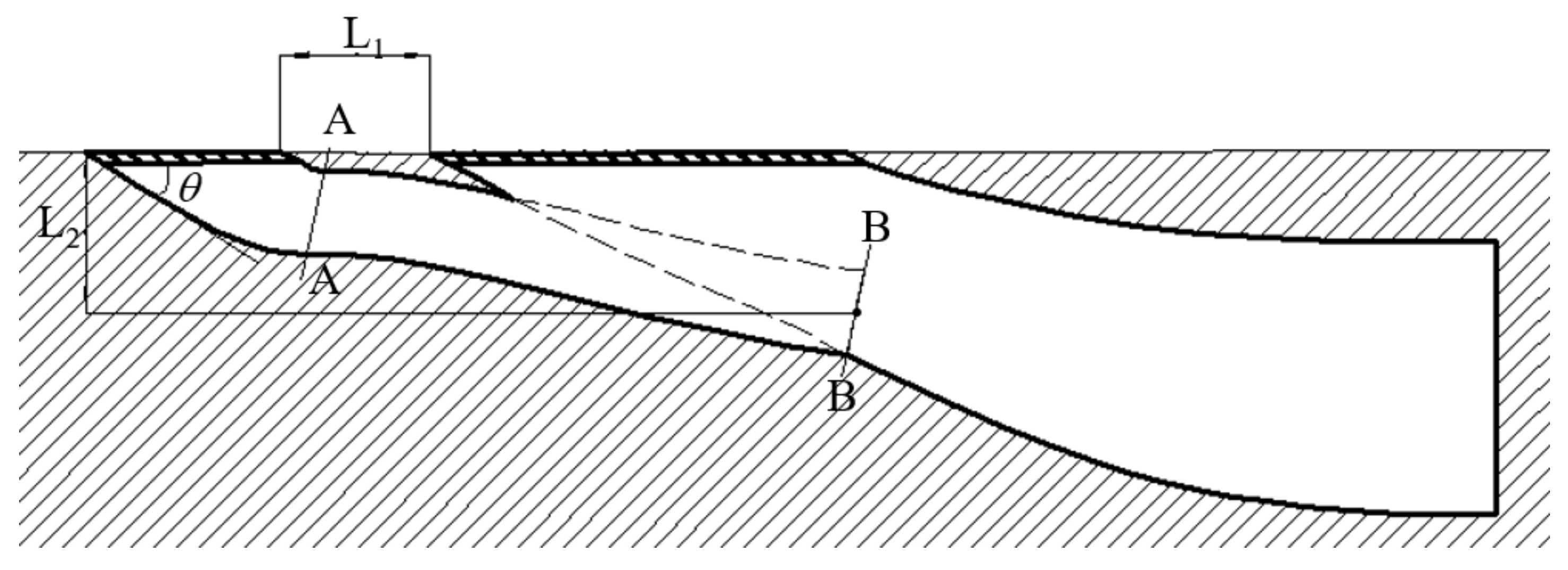
Parameter optimization, as a mature technology, has been widely used in designing advanced aircraft. This section presents the construction process of the optimization model and its results, but does not delve into the optimization algorithm’s details. The design parameters of the front auxiliary inlet, as shown in
Figure 6, primarily include the diversion angle
; the entrance area
Sfront,open; the throat area
Sfront,throat, which is the cross-sectional area of the front auxiliary inlet at A–A in the figure; the exit area
Sfront,outlet, which is the cross-sectional area of the front auxiliary inlet at B–B in the figure; the area expansion ratio
k, which is the ratio of the outlet area of the front auxiliary inlet to the throat area; the distance between the rear lip of the front auxiliary inlet and the front lip of the main inlet
L1; and centerline offset of the front auxiliary inlet
L2.
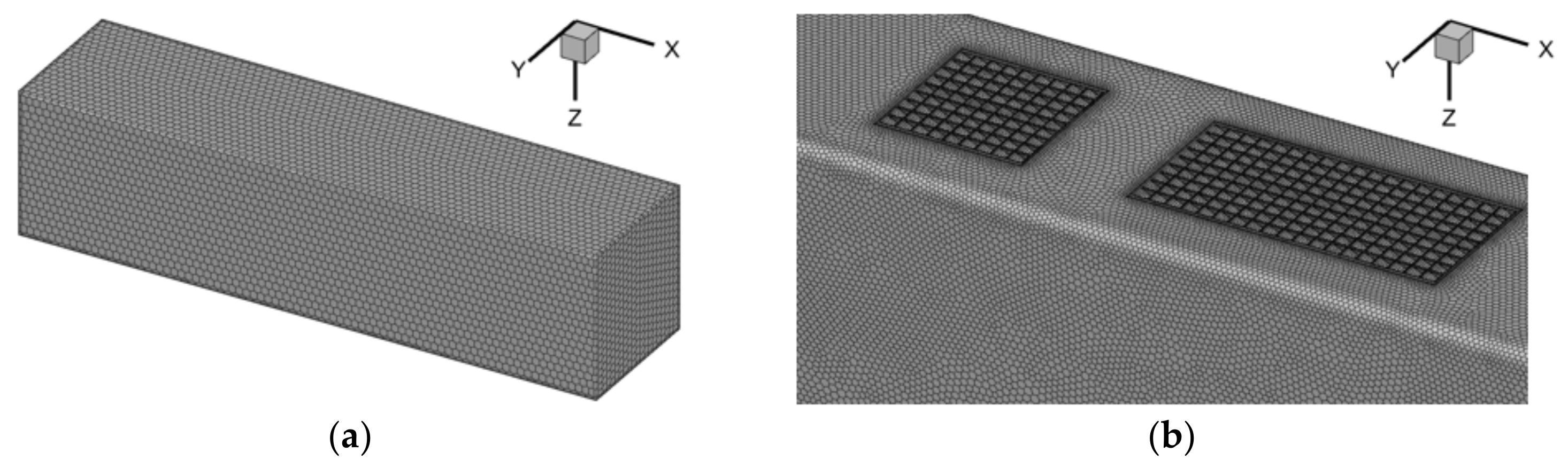
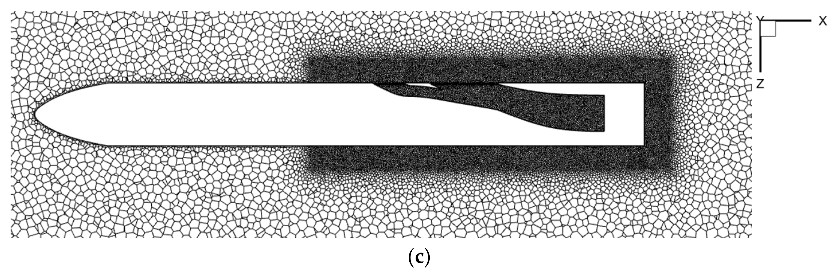
The parameters of the front auxiliary inlet configuration are optimized based on the particle swarm optimization (PSO) algorithm. Firstly, based on the existing inlet design experience, the preliminary design parameters of the front auxiliary inlet are given. Next, the configuration is parameterized based on the initial design, simplifying optimization of the original geometric model of the front auxiliary inlet into the optimization of its design parameters. It should be noted that since the inlet entrance is covered with a grille, the spanwise length was kept unchanged throughout the optimization process to maintain the integrity of each grille hole. The opening area of the front auxiliary inlet is controlled by adjusting the number of grille holes along the flow direction.
In the established optimization model, the algorithm parameters are set as follows: the number of iterations is 150; particle number 20; global increment 0.9; particle increment 0.9; inertial factor 0.9; maximum speed 0.1; and the maximum number of failed iterations is 5. The design variables are (
k,
L1,
L2,
n). The optimization goal is to obtain the maximum ratio of the total pressure recovery coefficient to the total pressure distortion index. The formula is as follows:
where
is the total pressure recovery coefficient;
PAIP is the average total pressure (mass-averaged) of the AIP section;
P0 is the total pressure of the incoming flow;
D1 is the total pressure distortion index;
PAIP,max is the maximum total pressure of the AIP section;
PAIP,min is the minimum total pressure of the AIP section; and
is the ratio of the total pressure recovery coefficient to the total pressure distortion index.
The optimization model can be described as follows:
The range of design variables and optimization results are shown in
Table 2.
5. Results and Analysis
This section investigates the impact of the front auxiliary inlet on the inlet performance, with a focus on the boundary layer development, total pressure distribution, Mach number distribution, and streamwise vortex development. Both cases where the inlet was equipped with and without the front auxiliary inlet are examined. Additionally, a study on the adaptability of the front auxiliary inlet under off-design conditions was conducted.
5.1. Boundary Layer Development Upstream of Inlet
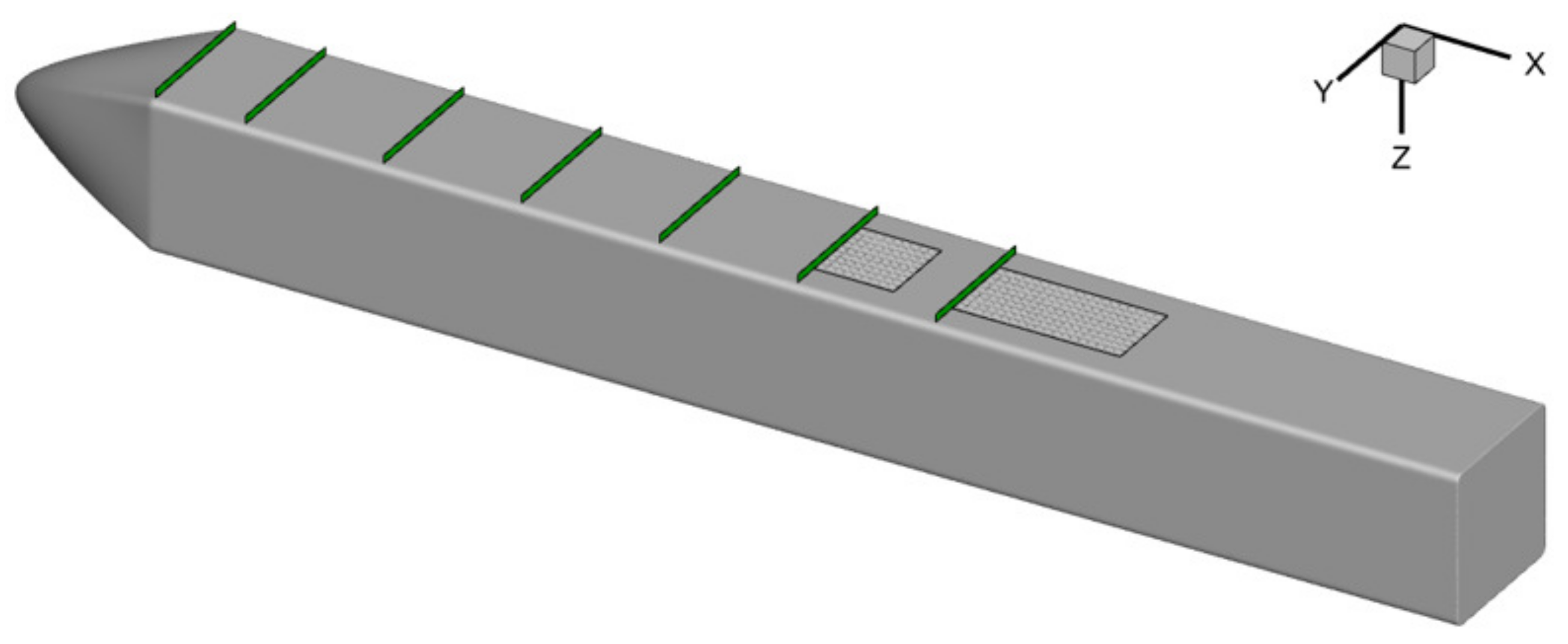
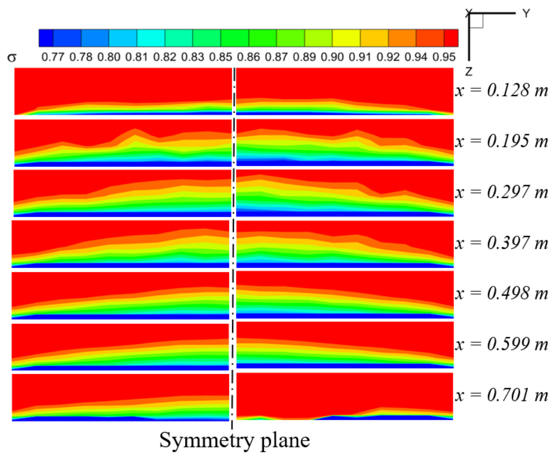
As shown in
Figure 12, there are seven monitoring surfaces arranged in the direction of airflow on the missile body surface. Each monitoring surface measures 101 mm in width and 11 mm in height. The x-coordinates of the monitoring surfaces are 0.128 m, 0.195 m, 0.297 m, 0.397 m, 0.498 m, 0.599 m, and 0.701 m, respectively. The sixth monitoring surface is aligned with the leading edge of the opening of the front auxiliary inlet on the missile body surface, while the seventh monitoring surface is aligned with the leading edge of the opening of the inlet on the missile body surface.
Figure 13 illustrates the distribution of the total pressure recovery coefficient on the monitoring surfaces. Due to the high level of symmetry, a half-model representation is used. The left side represents the without front auxiliary inlet configuration, while the right side represents the front auxiliary inlet configuration. The dashed line in the middle indicates the position of the symmetry plane. As observed, the low-energy airflow accumulates gradually along the flow direction, leading to an increase in the boundary layer thickness. After the
x = 0.297 m position, the boundary layer thickness reaches a steady state due to the effect of the friction force acting on the missile body surface. The total pressure distribution before
x = 0.599 m remained consistent with and without the front auxiliary inlet.
At the x = 0.701 m position, the thickness of the boundary layer of the front auxiliary configuration significantly decreased near the symmetry plane, which is one-fifth of that observed in the without front auxiliary configuration. This is because the low-energy airflow near the symmetry plane flows into the front auxiliary inlet; however, the length from the trailing edge of the front auxiliary inlet to the leading edge of the main inlet is limited and, as a result, the boundary layer is still in the initial stage of accumulation and has not yet formed at a larger scale.
5.2. Total Pressure Recovery Coefficient Distribution
5.2.1. The Distribution of Total Pressure Recovery Coefficient on the Symmetry Plane
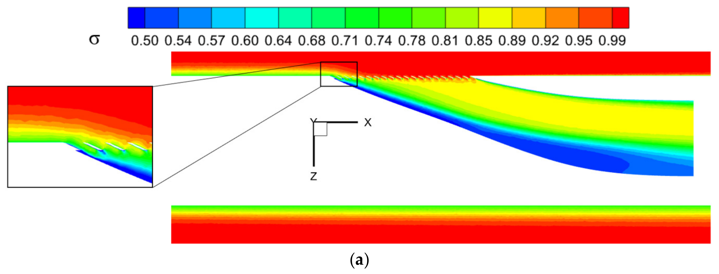
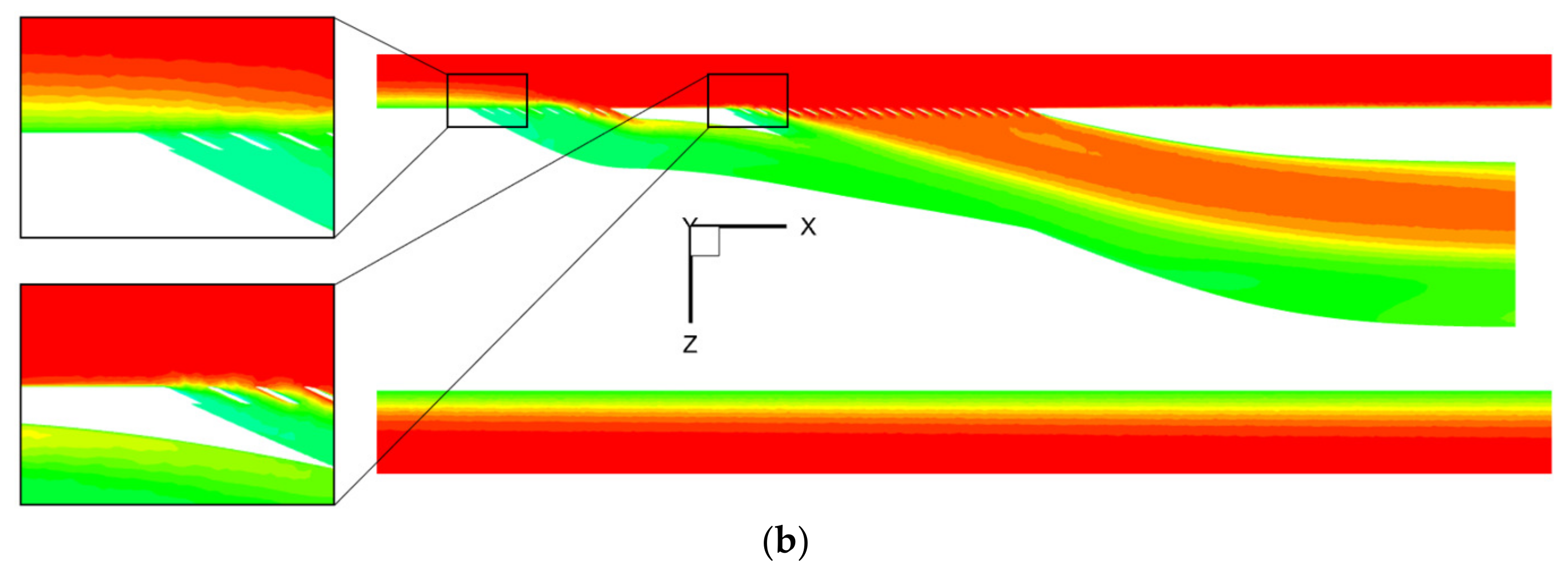
The distribution of the pressure recovery coefficient on the symmetry plane is shown in
Figure 14. The airflow with lower total pressure in the boundary layer of the without front auxiliary inlet configuration flows directly into the inlet from the front edge of the inlet and forms an obvious low-pressure area on the side with a larger radius of curvature.
For the front auxiliary inlet configuration, the low-energy flow in the boundary layer mainly flows into the front auxiliary inlet from the front edge of the front auxiliary inlet. The low-energy flow into the main inlet is significantly less than the without front auxiliary inlet configuration. The thickness of the boundary layer at the front lip of the main inlet is about one-fifth of that of the without front auxiliary inlet configuration, and there is no obvious low-pressure area on the side of the inlet with a larger internal curvature radius. The total pressure recovery coefficient inside the inlet is significantly higher than that of the without front auxiliary inlet configuration.
5.2.2. The Distribution of Total Pressure Recovery Coefficient along the Flow Direction
Five monitoring surfaces are arranged inside the inlet in the direction of airflow, as depicted in
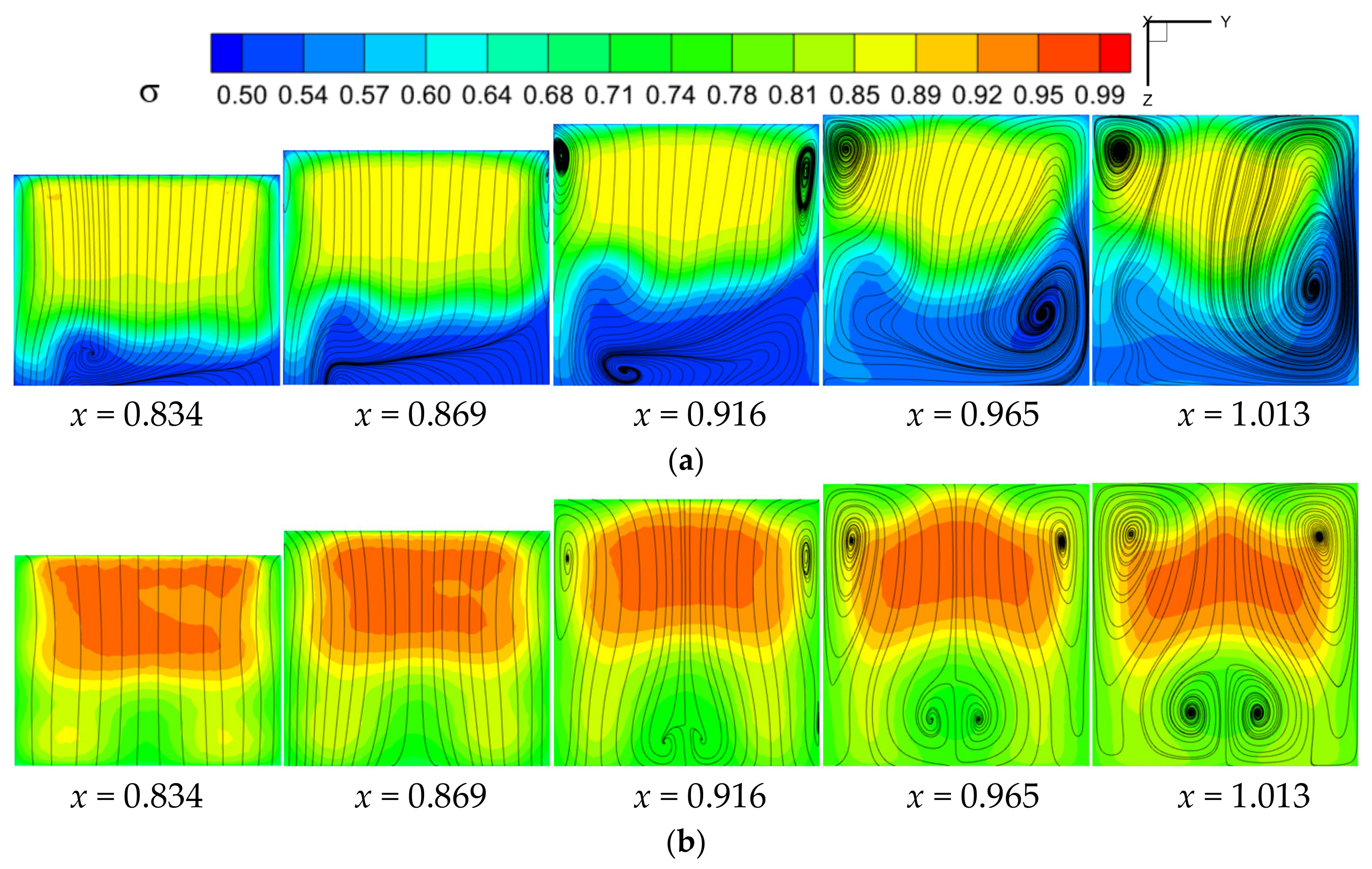
Figure 15. The x-coordinates of the monitoring surfaces are 0.834 m, 0.869 m, 0.916 m, 0.965 m, and 1.013 m, respectively. The fifth monitoring surface is located at the inlet exit.
The total pressure recovery coefficient distribution with streamlines at the monitoring surface of the without front auxiliary inlet configuration is shown in
Figure 16a. After the low-energy airflow flows into the inlet, the obvious separation vortex is formed on the side of the larger curvature radius of the inlet. The low-energy airflow at
x = 0.834 m only accounts for one-fifth of the monitoring surface area. With the further development of the airflow in the inlet, the area of the low-energy airflow gradually increases due to the friction of the inlet wall and the mixing between different velocity airflows. After
x = 0.916 m, the low-energy airflow accounts for more than a third of the monitoring area. It can be seen from the streamline diagram that the separation vortex at
x = 0.869 m only appears at the low-energy airflow on the side of the larger curvature radius of the inlet. With the flow of the airflow, the friction on the wall of the inlet continues to consume the energy of the airflow. At
x = 0.916 m, a pair of separation vortices is also generated on the side with a smaller radius of curvature of the inlet, closer to the wall. As the flow’s energy further dissipates, at
x = 0.965 m, the separation vortex in the upper right corner merges with the bottom separation vortex, forming a larger-scale separation vortex. The scale of the merged separation vortex further expands at
x = 1.013 m.
Figure 16b displays the distribution of the total pressure recovery coefficient with streamlines in the monitoring surface of the front auxiliary inlet configuration. At
x = 0.834 m and
x = 0.869 m, the airflow is relatively uniform, and there is no evident separation phenomenon. This is due to the fact that the majority of low-energy airflow flows into the front auxiliary inlet, resulting in higher airflow energy in the main inlet and a more uniform flow field, thus improving its ability to resist separation. As the flow develops, at
x = 0.916 m, it is influenced by the friction of the inlet wall and the pressure gradient, leading to the formation of a pair of separation vortices near the wall on the side of the inlet with a smaller radius of curvature. Additionally, a pair of separation vortices also form at the middle position on the side of the inlet with a larger radius of curvature. These separation vortices gradually increase in size at
x = 0.916 m and
x = 1.013 m. By comparing
Figure 16a,b, it is apparent that the configuration with the front auxiliary inlet has a significantly higher total pressure recovery coefficient and a stronger resistance to separation compared to the configuration without the front auxiliary inlet.
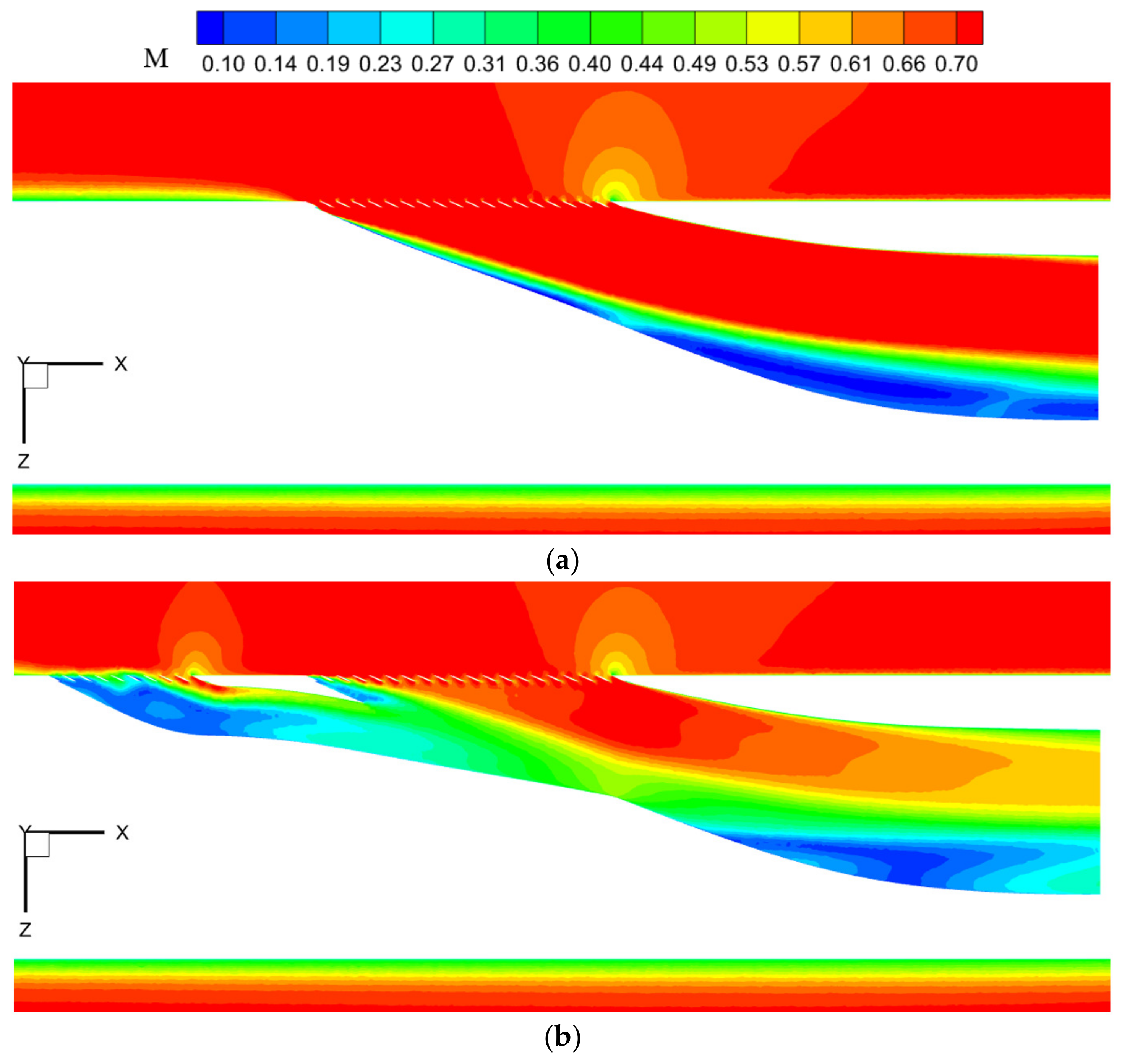
5.3. Mach Number Distribution
Figure 17 displays the distribution of the Mach number on the symmetry plane. In
Figure 17a, it is evident that stratification exists between the high- and low-speed airflows. The airflow velocity on the side with a larger radius of curvature is significantly lower than that on the side with a smaller radius of curvature. As the airflow develops within the inlet, the low-energy airflow near the wall boundary layer and the airflow away from the boundary layer interfere with one another. The low-energy airflow exerts a significant “drag” effect on the high-energy airflow and fast flow rate, while the fast-flowing, high-energy airflow rolls the low-energy airflow with a slow flow rate from the wall position to the center of the inlet. Finally, an evident separation vortex forms on the side with a larger radius of curvature, contributing to strong mixing loss.
In
Figure 17b, a large amount of low-energy boundary layer airflow enters the front auxiliary inlet, resulting in noticeable separation phenomena within the duct. A small amount of low-energy airflow from the boundary layer enters the main inlet, causing slight separation near the leading edge of the duct; however, as the flow progresses, these separation vortices are inhibited. Furthermore, comparing
Figure 17a with
Figure 17b, it is evident that the configuration with the front auxiliary inlet better accomplishes the task of decelerating and pressurizing the incoming flow, while also providing a more uniform internal flow field.
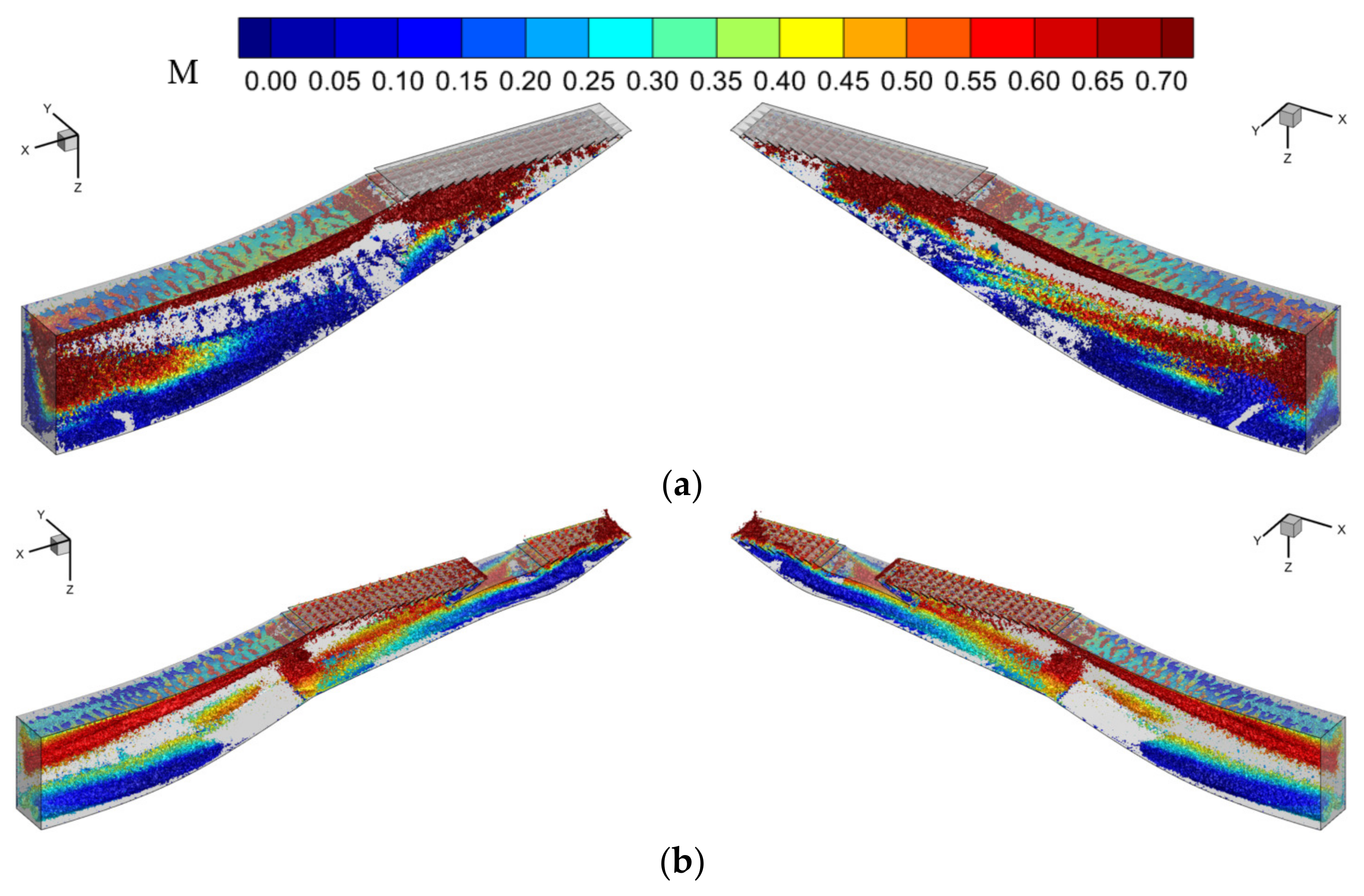
5.4. Development of Streamwise Vortices
To conduct a more detailed and comprehensive study on the formation and evolution process of vortices inside the intake duct, the computational domain inside the duct is divided into left and right sections at the symmetry plane, and each section is presented separately.
Figure 18 shows the iso-surface of vortices. The most widely used Q-criterion was chosen as the method to identify the vortices, and the iso-surface is colored based on the Mach number.
Figure 18a reveals that the streamwise vortices in the without front auxiliary inlet configuration begin to develop from the grille, with the scale increasing along the flow direction, and reach maximum intensity near the outlet. With the low-energy airflow in the boundary layer flowing directly into the inlet, the airflow has a strong mixing phenomenon at different speeds near the inlet exit, forming numerous separation vortices and creating a high degree of inhomogeneity in the flow field.
In
Figure 18b, the streamwise vortex in the front auxiliary inlet configuration begins to develop from the grille at the inlet of the front auxiliary inlet. Due to the low-energy airflow in the boundary layer flowing into the front auxiliary inlet, evident airflow separation occurs inside the front auxiliary inlet; however, the separation vortex does not develop along the flow direction and expand the scale, and even the scale of the downstream streamwise vortex at the intersection of the front auxiliary inlet and the main inlet is significantly reduced.
By observing the vorticity diagram on the iso-surface, it can be seen that the front auxiliary inlet and the main inlet form an ejector-like device. Firstly, the low-energy airflow is absorbed by the front auxiliary inlet to ensure that the airflow flowing into the main inlet is of high energy. Then, the high-speed and high-energy flow in the main inlet ejects the low-speed, low-energy flow in the front auxiliary inlet. At the intersection of the front auxiliary inlet and the main inlet, through the mixing effect, the high-speed and high-energy flow in the main inlet transfers energy to the low-speed and low-energy flow flowing out of the front auxiliary inlet, which suppresses the development of the separation vortex on the side with a larger curvature radius of the inlet. The mixed flow formed by mixing exhibits good uniformity, and there is no evident separation vortex within a specific range downstream of the intersection. With the inlet wall friction, a certain scale of separation vortex is formed near the outlet wall, but this separation vortex’s scale is significantly smaller than that of the inlet without a front auxiliary inlet.
5.5. Applicability of the Front Auxiliary Inlet under Different Operating Conditions
The total pressure recovery coefficient’s size illustrates the extent of flow losses, with a larger value indicating lower flow losses. The total pressure distortion index reflects the level of distortion within the flow field, determined by the difference between the maximum and minimum values of the total pressure across the entire plane. The formulas for calculating the total pressure recovery coefficient (
) and the total pressure distortion index (
D1) are shown in Formula (1).
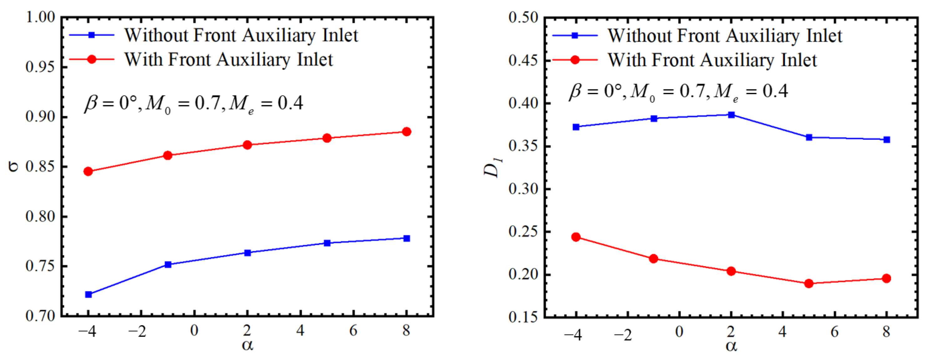
Table 6 displays the total pressure recovery coefficient and total pressure distortion index at the outlet of the two inlet configurations when
M0 = 0.7,
= 0, and
= 2°. The total pressure recovery coefficient at the outlet of the front auxiliary inlet configuration is 0.8719, with a total pressure distortion index of 0.2041. Compared to the inlet configuration without a front auxiliary inlet, the average total pressure recovery coefficient at the outlet increases by 12.39%, and the total pressure distortion index reduces by 47.24%.
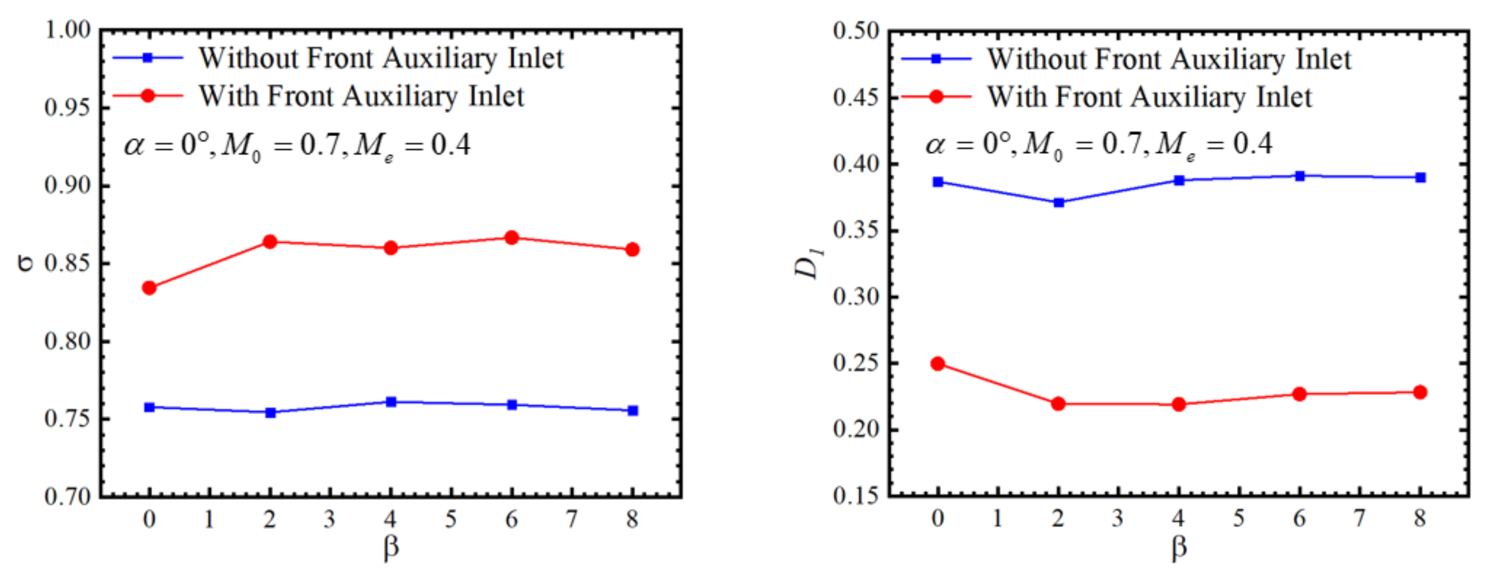
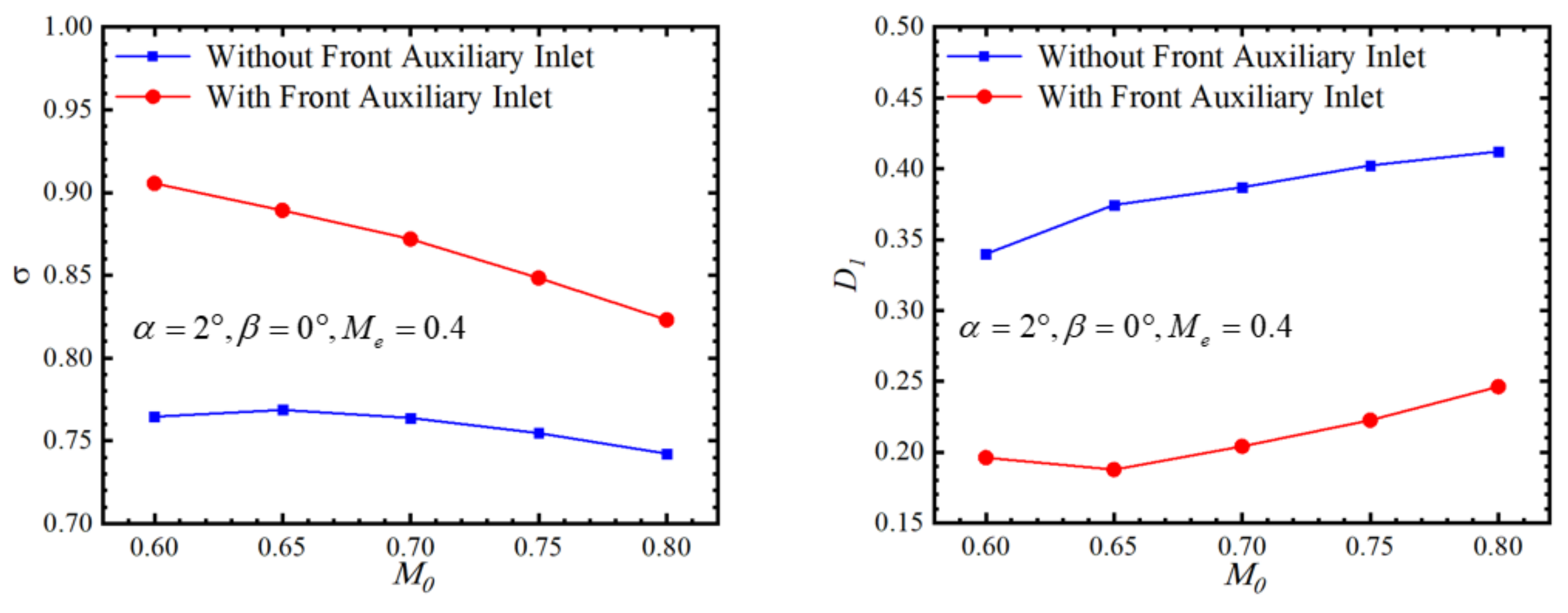
Figure 19,
Figure 20 and
Figure 21 present a comparison of the inlet performance under different angles of attack, angles of sideslip, and inflow Mach numbers. The results demonstrate that the front auxiliary inlet significantly improves the intake quality within the calculated range. It is noteworthy that its performance advantage is not limited to specific operating conditions but exhibits wide applicability. This implies that the front auxiliary inlet can enhance the inlet performance across various flight conditions. It maintains the uniformity and stability of the incoming airflow, delivering higher-quality air to the engine, thereby improving engine efficiency and performance; therefore, the front auxiliary inlet is regarded as a solution with broad applicability, capable of meeting the requirements of inlet performance under different operating conditions.
6. Multi-Parameter Sensitivity Analysis of Front Auxiliary Inlet
The selection of parameters for the front auxiliary inlet has a significant impact on the intake performance. During the design process, it is crucial to determine the extent of the influence of the design parameters on the performance indicators. This can greatly enhance design efficiency and reduce the design cycle. In this section, a standardized dimensionless method is utilized to calculate the sensitivity , reflecting the influence of the design parameters of the front auxiliary inlet on the characteristic index. Next, the Pareto diagram depicts the proportion of the influence of multiple front auxiliary inlet parameters on the total pressure recovery coefficient and total pressure distortion index at the inlet outlet .
The Pareto diagram serves as a parameter sensitivity analysis tool, displaying the primary factors influencing a particular index. Formulas (3) and (4) exhibit the calculation formulas for
and
, respectively. When
is positive, it indicates an overall increase in the indicators with an increase in the local parameters, and the two demonstrate a positive correlation as a whole. Conversely, when
is negative, it suggests an overall index decrease with an increase in the local parameters, and the two reveal a negative correlation as a whole.
describes the proportion of the influence of each local parameter on the overall index when multiple local parameters affect a particular overall index. The sum of the impact of each parameter in the same Pareto diagram on the overall index should be 100%.
In Formula (3),
is the value of the local parameters;
is the value of the overall index when the local parameter takes
; and
is the value of the local parameter of item
.
In (4), denotes the local parameter of item and represents the number of local parameters.
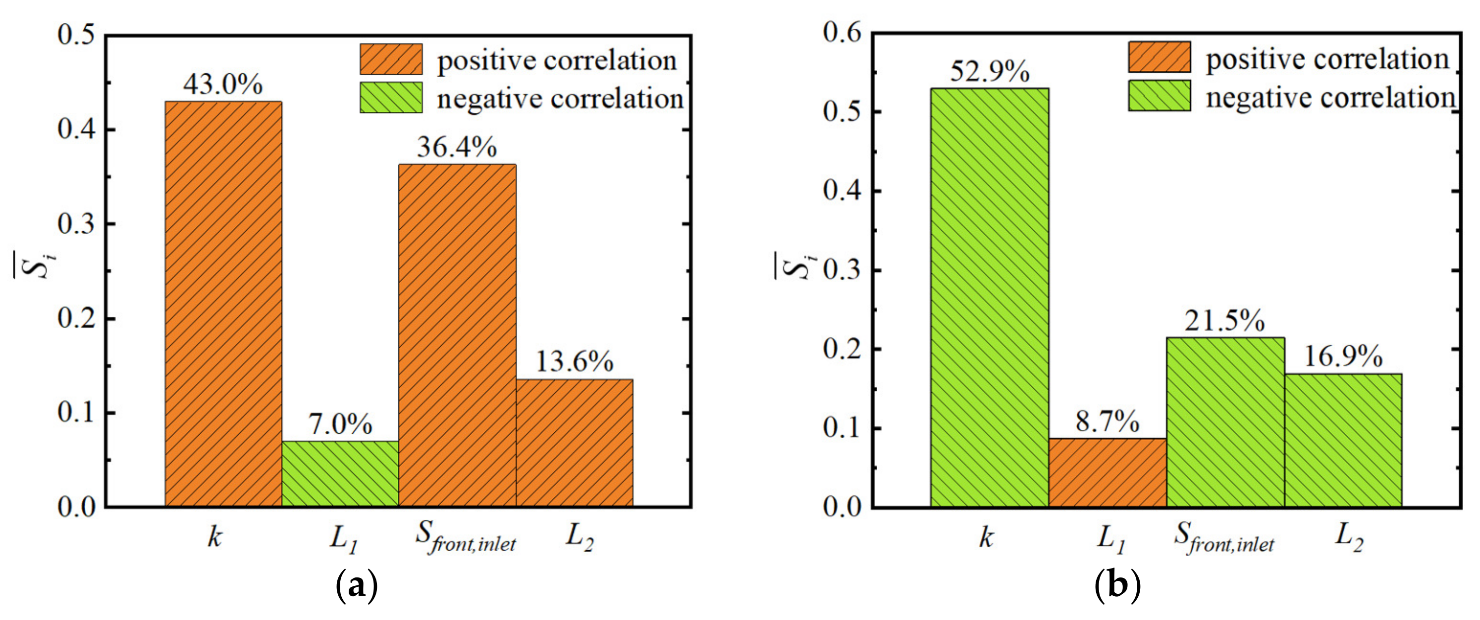
Figure 22 displays the Pareto diagram for the primary parameters of the front auxiliary inlet on intake performance. Orange represents a positive correlation, while green signifies a negative correlation. Among the main parameters of the front auxiliary inlet, the area expansion ratio (
k) has the most significant impact on the total pressure recovery coefficient and distortion index, accounting for 43.0% and 52.9%, respectively. The second parameter is the front auxiliary inlet opening area (
Sfront,inlet), which is responsible for 36.4% and 21.5% of the total pressure recovery coefficient and distortion index, respectively. The third parameter is the centerline offset of the front auxiliary inlet (
L2), which accounts for 13.6% and 16.9% of the total pressure recovery coefficient and distortion index, respectively. The distance between the rear lip of the front auxiliary inlet and the front lip of the main inlet (
L1) has the least influence on the total pressure recovery coefficient and distortion index, accounting for 7.0% and 8.7%, respectively.


