Article

Gust Response of Spanwise Morphing Wing by Simulation and Wind Tunnel Testing

School of Aeronautic Science and Engineering, Beihang University, Beijing 100191, China
*
Authors to whom correspondence should be addressed.
Aerospace 2023, 10(4), 328; https://doi.org/10.3390/aerospace10040328
Submission received: 14 December 2022 / Revised: 14 March 2023 / Accepted: 23 March 2023 / Published: 24 March 2023
(This article belongs to the Special Issue Aerodynamics Design)

Abstract

:
The spanwise morphing wing can change its aerodynamic shape to suit its flight environment, thereby having the potential to improve the flight performance of the aircraft, especially in gusty conditions. To investigate the potential of morphing wings, the aerodynamic performance of a spanwise morphing wing with a flapping wingtip in a gust environment was analyzed in this paper. The aerodynamic characteristics of the morphing wing are hard to measure accurately, and thus a wind tunnel test was carried out to study the influences of morphing parameters, such as the morphing length, amplitude and frequency on the gust alleviation effect. The flow mechanism of the designed spanwise morphing wing was analyzed in detail by the instantaneous lift results of the wind tunnel test and the flow field results of the CFD method. The results have shown that with appropriate morphing parameters, the spanwise morphing wing designed in this paper can effectively achieve gust alleviation during flight. The conclusions obtained in this paper can be useful guidance for the design of morphing aircraft.

1. Introduction

As mission scenarios in military and civil aviation have become more complex and changeable, traditional aircraft have gradually been unable to meet the requirements for efficient flight, high-speed maneuvering, mission adaptation, high autonomy and other capabilities of aircraft. Alternatives such as adopting new aerodynamic layouts, propulsion systems and materials can improve flying efficiency. Among all these methodologies, the morphing wing has attracted extensive attention recently [1,2,3].
The inspiration for morphing wings comes from flying creatures. Insects can quickly and passively change the chord shape by flapping their wings up and down and improve their aerodynamic performance by changing the camber of the airfoil [4]. Birds can change lift and thrust by changing the overlapping of feathers, controlling the spanwise camber deformation of their wingtip feathers, moving the position of the bastard wing, and actively folding wings in the process of flapping up and down [5,6]. Bats have a highly flexible membrane structure and a high degree of freedom of joints, so they have considerable maneuvering ability during flight [7,8]. Moreover, in a strong wind environment, which is common in nature, flying creatures, such as owls, achieve stable flight by changing their wings and body posture [9]. Large birds, such as albatrosses, realize the utilization of wind energy through the simple movement of their wings [10]. Learning from nature, it can be seen that morphing wing technology can improve not only the aerodynamic efficiency of aircraft but also possibly improve their flight ability in gusty environments.
Through studying flying creatures, various types of aircraft with morphing capabilities have been developed [11,12]. Among them, the spanwise morphing wing has greatly raised researchers’ attention [13,14]. The morphing actuator structure of the morphing wing is often complex, which imposes a large structural weight on the aircraft. However, the spanwise morphing wing has fewer morphing actuators and can be integrated with the wing structure, thus effectively improving reliability. Additionally, the spanwise morphing wing has significant deformation, which can adapt to more flight conditions. Moreover, it has the advantages of low lift drag and long endurance [15]. Most designs of spanwise morphing wing allow for the spanwise shrinkage of the wings, which can reduce the spanwise length and facilitates aircraft storage in hangars [16].
Due to the various advantages of the spanwise morphing wing mentioned above, there have been many research studies on it in recent years, and some achievements have been attained. The Khalifa University of Science and Technology designed an active span morphing wing for small UAVs. By actively extending the span up to 25%, the aerodynamic efficiency of the morphing wing can be enhanced [17]. Cellular metamaterials have also been used to implement spanwise morphing, which allows the wing to have significant deformation while maintaining its load-bearing ability [18]. The gear-driven autonomous twin-wing SPAR (Gnatspar) mechanism was developed to achieve a 20% variation in wing length [19]. A rack-and-pinion-driven rigid extension length device was invented, so that the left and right wings could be independently controlled, and the extension length variation could reach 50%. On this basis, a multi-mission UAV with asymmetric extension length variation was developed [20]. Though many different kinds of spanwise morphing wings have been studied, there are a few studies investigating the spanwise morphing wing with a flapping wingtip. By combining the effects of the fixed wing and the appropriate reciprocating flapping of the wingtip, the flight performance of an aircraft can be significantly improved, especially in gusty conditions. Therefore, the purpose of this paper is to study the factors affecting the flight performance of spanwise morphing wings with a flapping wingtip and reveal the inherent law.
Gusty wind will change the attitudes of an aircraft suddenly and cause the aircraft to shake, thus posing a serious threat to flight performance and safety. Early technology to resist gusty wind often suggests to strengthen the structure, but this also increases the structure’s weight. In recent years, with the development of flexible aircraft which are more sensitive to gusty wind, gust alleviation technology has been put forward with higher requirements. Some studies have shown that spanwise morphing wing aircraft have the potential to achieve gust alleviation during flight [21,22,23]. Welstead et al. [24] designed a gust alleviation device with multiple free-wing segments, which could realize significant spanwise morphing and thus had a good alleviation effect on gust changes in both time and space. In the event of gusty winds, swinging wingtips can mitigate the effect of gusts and improve aircraft performance [25,26,27]. Castrichini et al. [28] designed a folding wingtip device for gust alleviation. The wingtip control and aircraft attitude control were independent of each other, which reduced the difficulty of gust alleviation control but also increased the weight of the wingtip. By mounting a passive gust alleviation device at the wingtip, the researchers found it can have great benefits on gust alleviation and flutter suppression [29]. For large passenger aircraft with a high aspect ratio wing, research has also shown the effectiveness of employing a passive twist wingtip to realize gust alleviation [30]. The gust alleviation effect is related to a variety of factors. The relationship between gust frequency and morphing frequency is one of the vital factors which is rarely seen in existing studies.
In order to investigate the influence of morphing parameters, morphing frequency and gust frequency on the gust alleviation effect, providing a basis for the design of active gust alleviation using morphing wing technology, this paper takes the spanwise morphing wing with a flapping wingtip as the research object to analyze its aerodynamic performance in gusty environments. The experimental demonstration is carried out through a wind tunnel test. Based on the test results, the influences of morphing parameters such as the length, amplitude and frequency on the gust alleviation effect are researched. The mechanism of different morphing parameters is analyzed in detail from the instantaneous aerodynamic data and flow field by using the CFD numerical simulation method.
The rest of the paper is arranged as follows. Section 2 introduces the wind test model, the test process and the data processing method. Section 3 gives the results and discussions of the wind tunnel test and the numerical simulation. The conclusions are presented in Section 4.

2. Test Model and Method

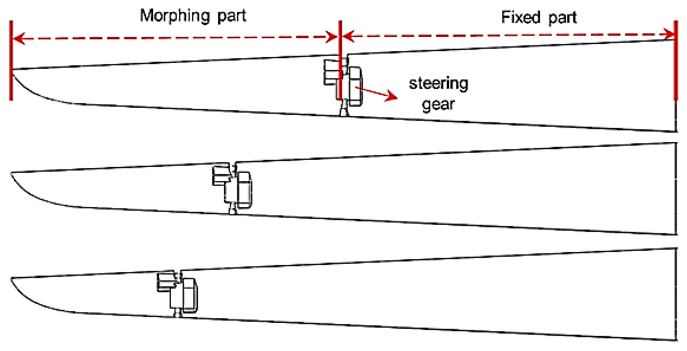
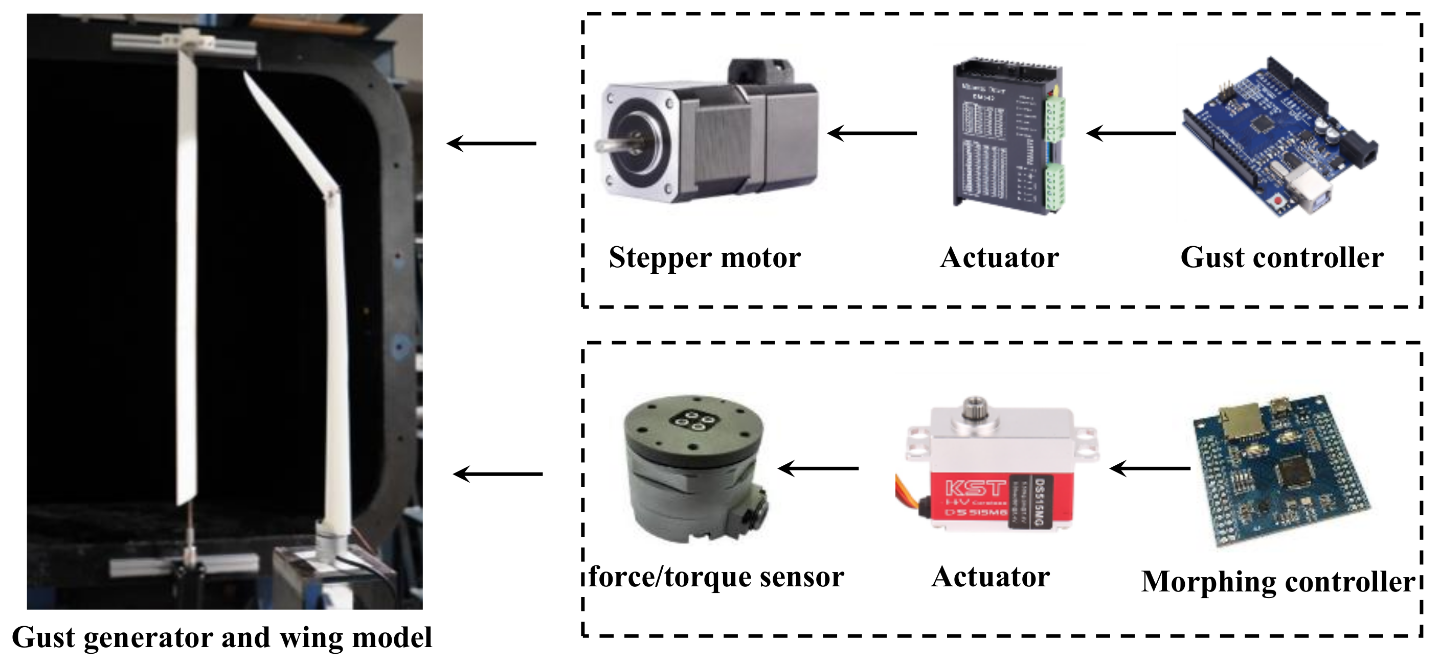
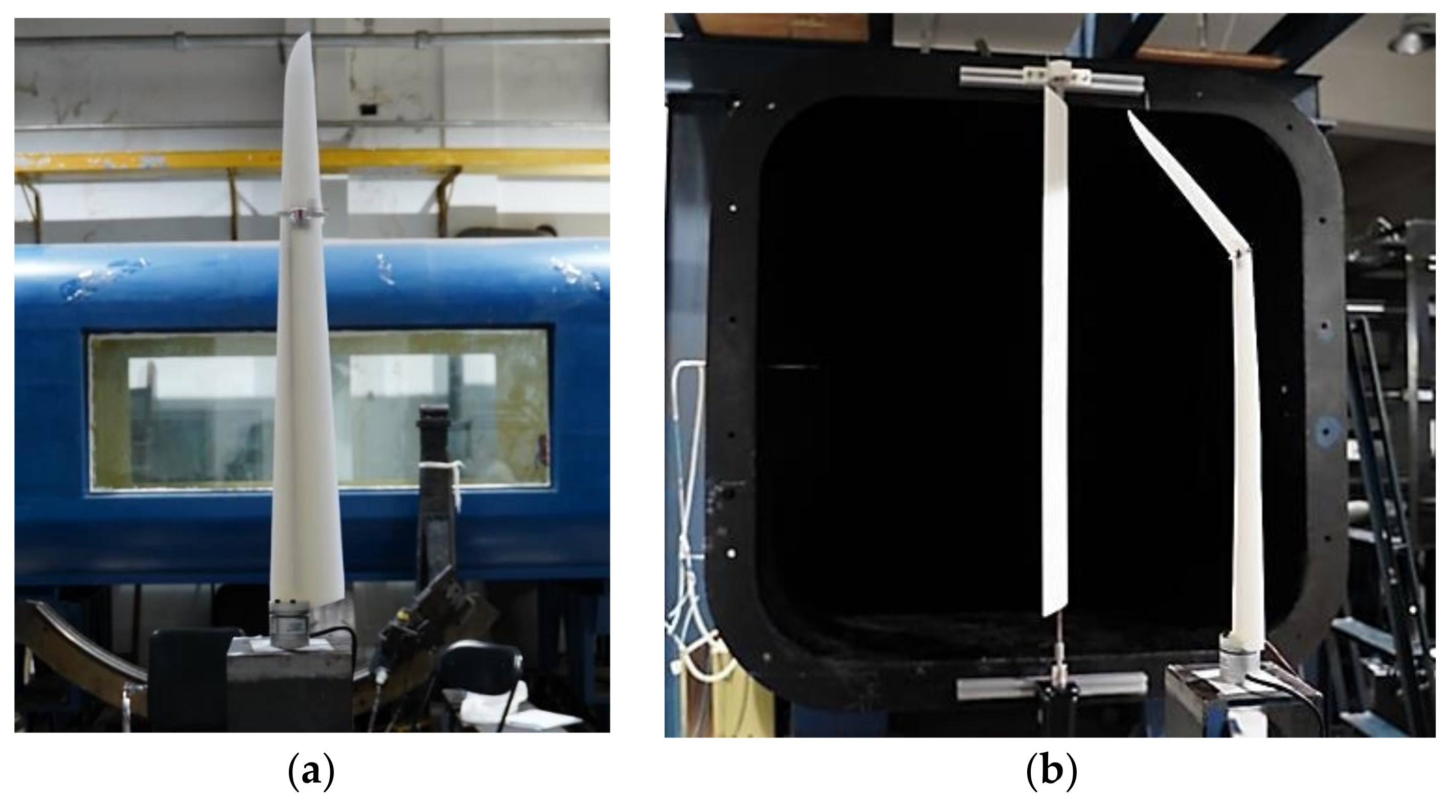
2.1. Wind Tunnel Test Model

In this paper, 3D printing technology is used to make spanwise morphing wings with different morphing part lengths. The geometrical details of the morphing wing are as follows: the half-span (represented by the symbol ‘b’ in the text) is 71 cm, the aspect ratio is 19.8, the airfoil used is SD-2048 and the length of the morphing part is 1/2, 1/3 and 1/4 of the half-span, respectively, as shown in Figure 1. The movement of the spanwise morphing wing is the flapping of the morphing part. The motion driver is the steering gear. By setting its flapping rule programmatically, the steering gear can reciprocate according to the sinusoidal rule within the specified range of the flapping angle, and its motion frequency is up to 5 Hz.
The experiment was carried out in the D4 wind tunnel at Beihang University. The length of the wind tunnel experimental section is 2.5 m × 1.5 m × 1.5 m. The maximum wind speed in the test section is 60 m/s. The flow velocity of this experiment is 6–14 m/s. The FC6D50 six-dimensional force/torque sensor (Shanghai Naichuang Test Technology Company, Shanghai, China) is selected as the force-measuring device. The sensor has a diameter of 5 cm, a height of 4.9 cm and a small volume, which can greatly reduce the influence of the sensor on the experimental results. The measuring range of the force is Fx = Fy = 100 N and Fz = 200 N, and the measuring range of the torque is Mx = My = Mz = 8 Nm.
To simulate a gusty environment, a gust generator was placed at the inlet of the wind tunnel, which was directly driven by a stepper motor, thus generating a sine-type gust. The whole gust generator is composed of a motion controller, a stepper motor, a power supply and a wing segment. Figure 2 shows the control system of the gust generator.
The stepper motor runs at a fixed angle for each pulse. The rotating speed is controlled by the pulse interval time of the modulating stepper motor controller. Thus, the gust generator can operate according to the specified motion law.

2.2. Test Process and Data Processing Method

2.2.1. Test Process

The test model was firmly connected with the 6-DOF sensor and installed on the model bracket with a variable angle of attack (AOA), which could easily measure the force and the moment of the wing under the different AOAs. The rotation axis is around the wing’s spanwise axis. The gust generator is installed on one side of the incoming flow, the upper end is fixed by a bearing and the lower end is directly driven by a stepper motor, as shown in Figure 3. In this paper, a gust model with a maximum vertical velocity of 2 m/s was selected. Meanwhile, considering the strength of the wing model and the characteristics of the wind tunnel, the inlet velocity was set at 11 m/s. The motion parameters of the gust generator are G1 (deflection angle 15°, deflection frequency 1 Hz), G2 (deflection angle 16°, deflection frequency 0.5 Hz) and G3 (deflection angle 14°, deflection frequency 2 Hz).
Before the test process of the experiment condition, the spanwise morphing wing was adjusted to the specified AOA, the wind tunnel blowing equipment and gust generator were started up, and the sensor data of this period were collected to measure the gust response of the wing without morphing. Then, when the gust generator was rotated to an appropriate angle, the spanwise morphing mechanism was activated so that the phase difference between the gust and spanwise morphing was almost zero, and the data required for the test were collected. That is, when the wind speed was down, the morphing part flapped downward to increase the lift force; when the wind speed was up, the morphing part moved upward to reduce the gust load. In the whole process, the unsteady aerodynamic force caused by the spanwise morphing reduced the fluctuation of the lift force and increased the average lift force. The preset morphing angle and gust velocity change are shown in Figure 4.
The test parameters are shown in Table 1, from which we can see there are 36 test conditions in total. For each test, the aerodynamic data at four AOAs are measured for each model. In each state of the AOA, the stepper motor is controlled to generate the specified test condition gust; the frequency and amplitude of the morphing part are controlled by the modulated steering gear through the single chip microcomputer, and the curve of the lift force, the thrust force, the torque and other changes with time are measured and recorded. The design of the test condition is to compare the aerodynamic characteristics of the large and small AOAs when the gust frequency is equal to, far greater than and far less than the morphing frequency. Considering the test restrictions, the form of fixed morphing frequency and amplitude to change the gust characteristics is adopted.

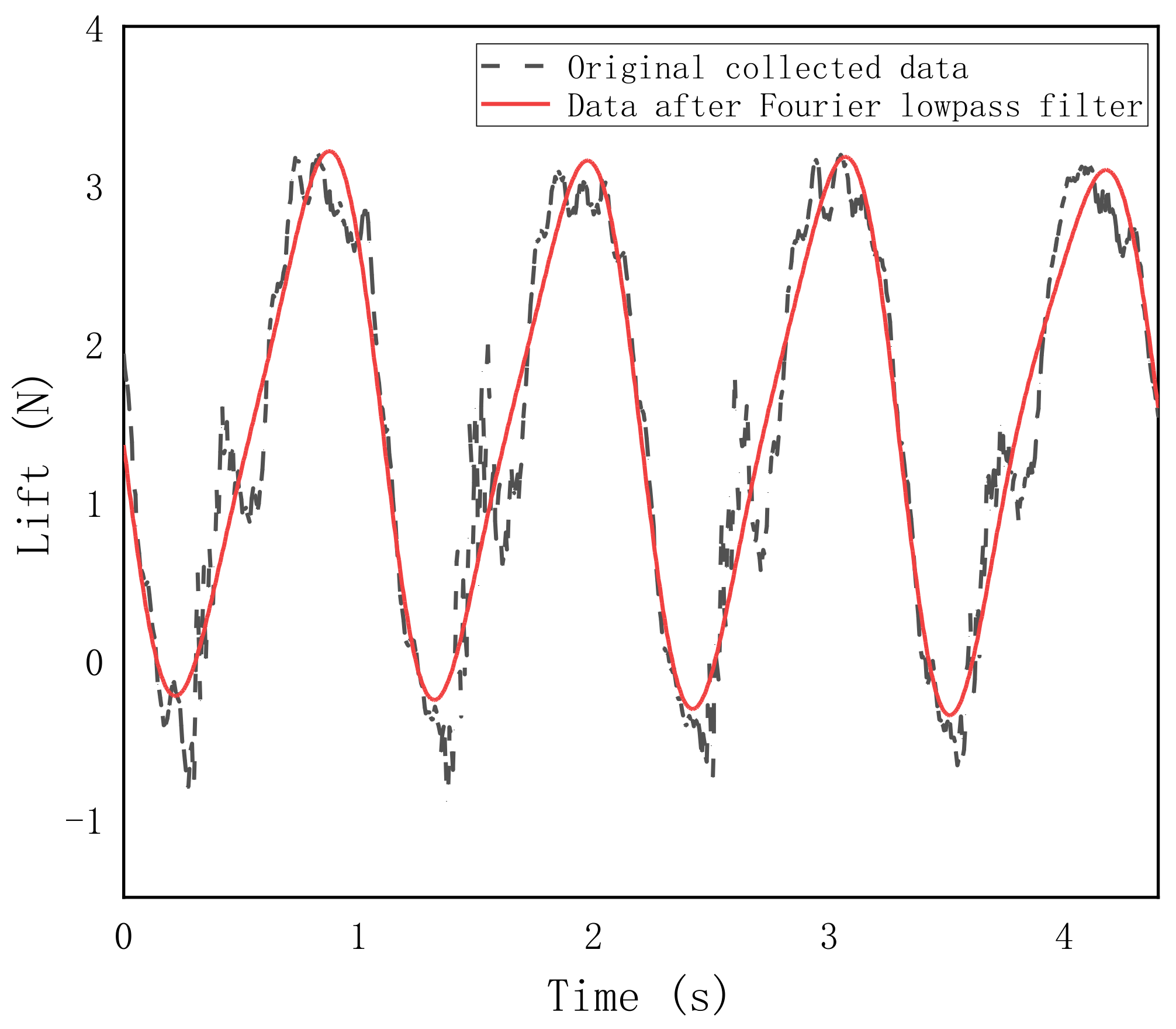
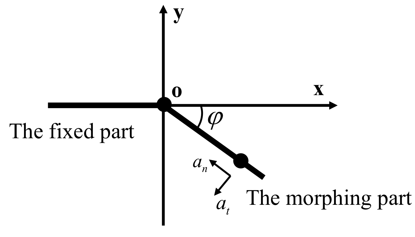
2.2.2. Data Processing

The measured data, due to the existence of multiple noises such as the vibration of the actuator and the morphing wing structure, need to be processed by filtering. In this paper, the Fourier transform method is used to realize the low-pass filtering of the collected data, thereby eliminating the interference of noise and obtaining the accurate average lift force.
Figure 5 shows the comparison between the originally collected data and the data after Fourier low-pass filtering. The test conditions are as follows: the incoming flow velocity is 11 m/s, the AOA is 0° and the gust model is G1. As can be seen from Figure 5, the data curve processed by Fourier filtering completely shows the aerodynamic characteristics under this test condition. The curve is smoother, and the data spike caused by the noises is eliminated.
Since the morphing part of the wing is flapping, the lift force measured by the test is the combination of inertia and aerodynamic force. In time domain data analysis, the inertial force value may be greater than or close to the aerodynamic force value, so it is necessary to subtract the inertial force from the measured data. In this paper, the influence of the inertial force on the aerodynamic force is removed by theoretical calculation.
Inertial forces are derived by the following process. As shown in Figure 6, the origin of the coordinate is the rotation axis of the morphing part; φ is the flapping angle, controlled by a single chip microcomputer, f = 1 Hz; ω is the angular velocity; α is the angular acceleration.
φ = 40 sin ( 2 π f t ) ω = 80 π f cos ( 2 π f t ) α = 160 π 2 f 2 sin ( 2 π f t )
an and at represent the circumferential and radial acceleration of flapping, respectively.
a n = ω 2 r a t = α r
Fn and Ft are inertial forces in the circumferential and radial directions, respectively;
F n = m a n = m r ω 2 F t = m a t = m r α
After force decomposition, the inertial forces Fx and Fy in the geodetic coordinate system are obtained, where Fy is the inertial force in the direction of the lift force.
F x = F t sin φ + F n cos φ = m r ω 2 sin φ + α cos φ F y = F t cos φ F n sin φ = m r ω 2 cos φ α sin φ
The required parameters of inertial force in the morphing part are calculated, which are shown in Table 2.
Finally, the variation of the inertial forces of the three models over time is obtained, as shown in Figure 7. The morphing angle upward is positive. When the morphing angle upward reaches the maximum, the inertial force reaches the minimum. When the morphing angle downward reaches the maximum, the inertial force reaches the maximum. By subtracting the inertial force data calculated theoretically from the lift data collected by the test, the pure aerodynamic lift completely caused by the wing morphing movement is obtained. The comparison between the original data and the pure aerodynamic lift force is shown in Figure 8.

2.3. Selection Reasons of the Testing Parameters

Before the selection of the morphing part length, flapping amplitude and morphing frequency, careful consideration was taken based on the test results. In this section, the selection reasons for these testing parameters are provided.

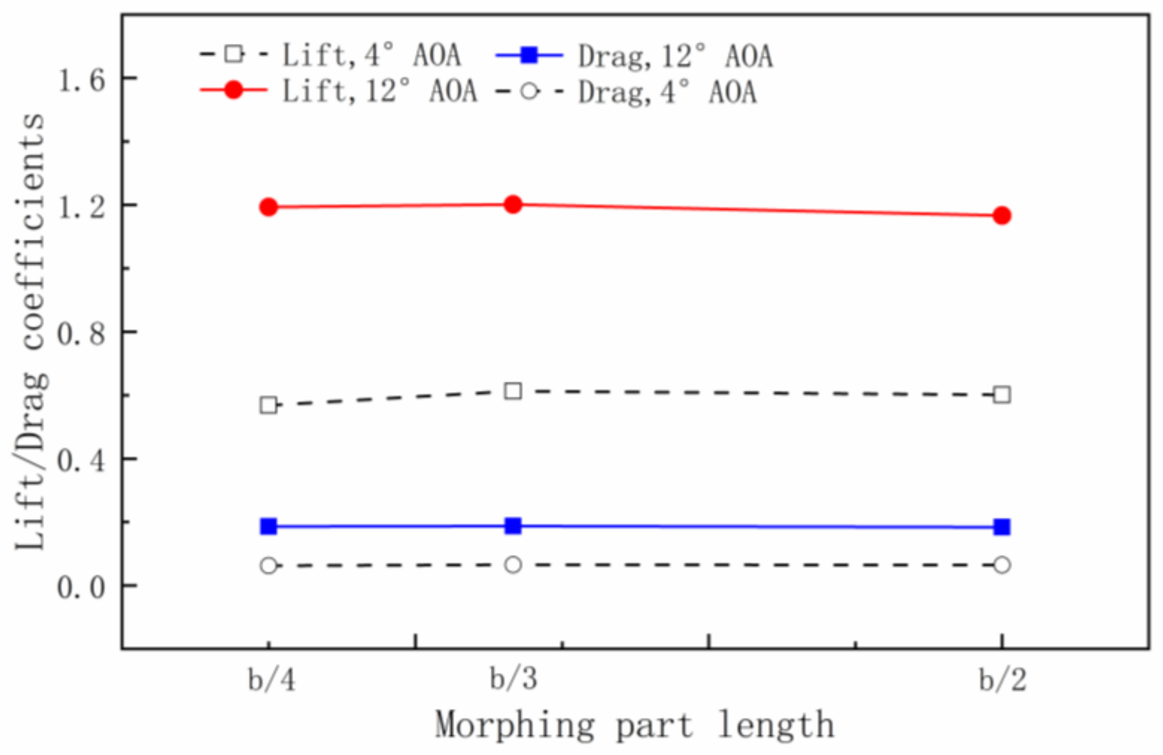
2.3.1. Morphing Part Length

Before choosing the morphing part length distribution, the influence of the morphing length on the aerodynamic characteristic is investigated. When the flapping amplitude is 40° and the morphing frequency is 1 Hz, the variations of lift and drag coefficients with morphing part lengths are shown in Figure 9.
From Figure 9, it can be seen that the spanwise morphing wing has a better aerodynamic characteristic at a certain point between the b/2 and b/4 morphing part length. However, searching for this point is complicated, and the improvement is limited even if it is found after a lot of effort. Therefore, after comprehensive consideration, the b/2, b/3 and b/4 morphing part lengths were selected.

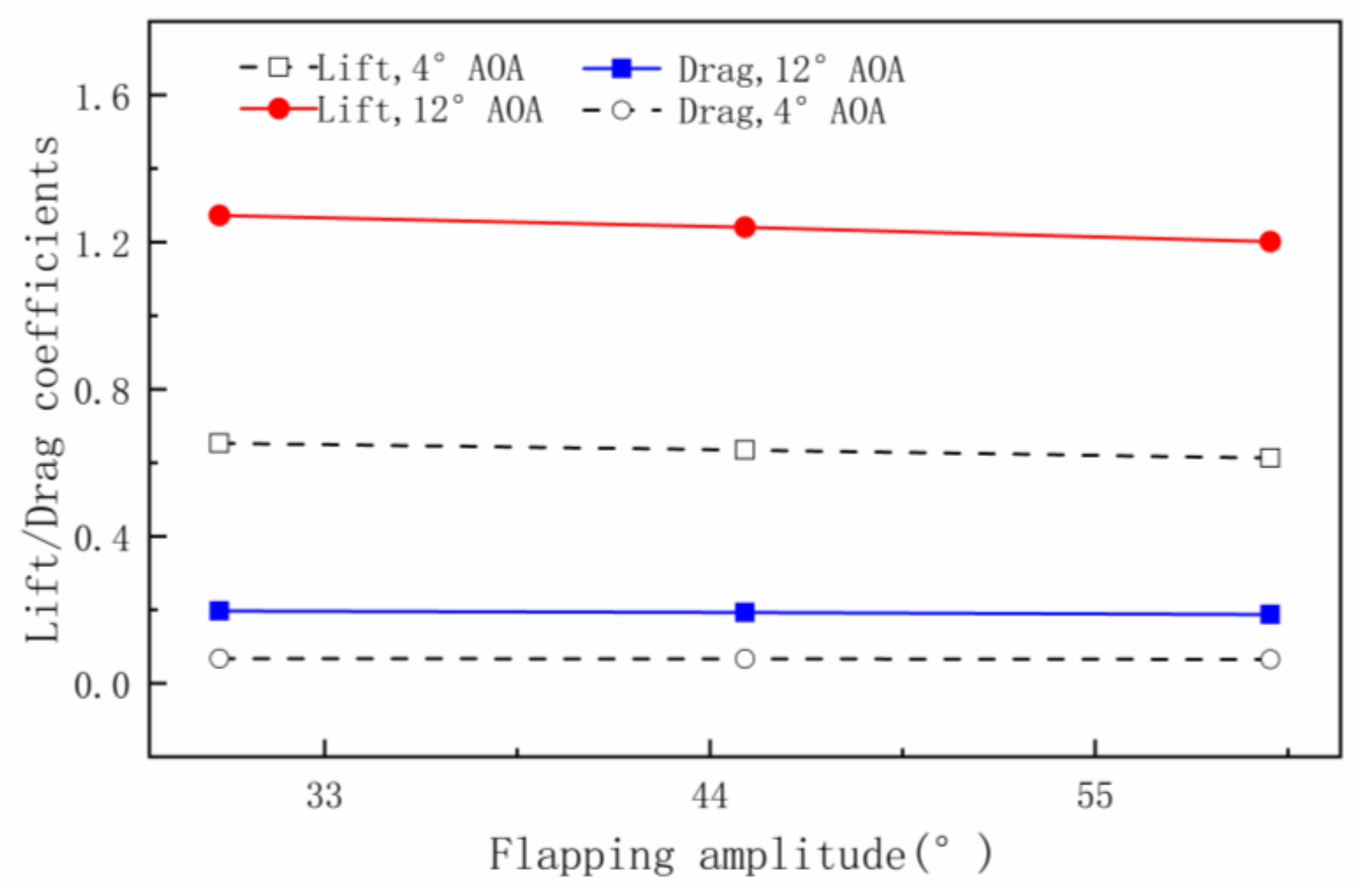
2.3.2. Flapping Amplitude

Before setting the flapping amplitude at 40°, the influence of the flapping amplitude on the aerodynamic characteristic is investigated. When the morphing frequency is 1 Hz, the variations of the lift and drag coefficients with flapping amplitude are shown in Figure 10.
From Figure 10, it can be seen that with the increase in flapping amplitude, the lift and drag coefficients both decrease gradually. Therefore, choosing a relatively small amplitude is more appropriate. However, a flapping amplitude of 30° is too small, whereas 45° will lose too much lift. Therefore, we set the flapping amplitude at 40°.

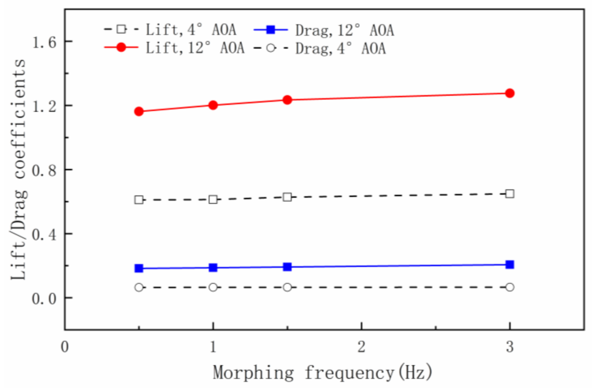
2.3.3. Morphing Frequency

Before setting the morphing frequency at 1 Hz, the influence of the morphing frequency on the aerodynamic characteristic was investigated. When the flapping amplitude is 40°, the variations of lift and drag coefficients with morphing frequency are shown in Figure 11.
From the figure, it can be seen that with the increase in the morphing frequency, the lift and drag coefficients also increase. However, the change is not obvious between 1 Hz and 3 Hz. At the same time, considering the need to study the relationship between morphing frequency and gust frequency, the morphing frequency is set at 1 Hz, which can help establish a dimensionless relationship with gust frequency.

3. Results and Discussions

3.1. Influence of Morphing Parameters

In this section, the morphing frequency is fixed at 1 Hz, the flapping amplitude is 40°, and the gust amplitude is 2 m/s. The aerodynamic characteristics of different spanwise morphing wings are analyzed under three kinds of gusts (the gust frequency is equal to the morphing frequency; the gust frequency is two times the morphing frequency, and the gust frequency is 0.5 times the morphing frequency). The gust alleviation effect can be concluded from the reduction in drag force, pitch moment and bend moment.

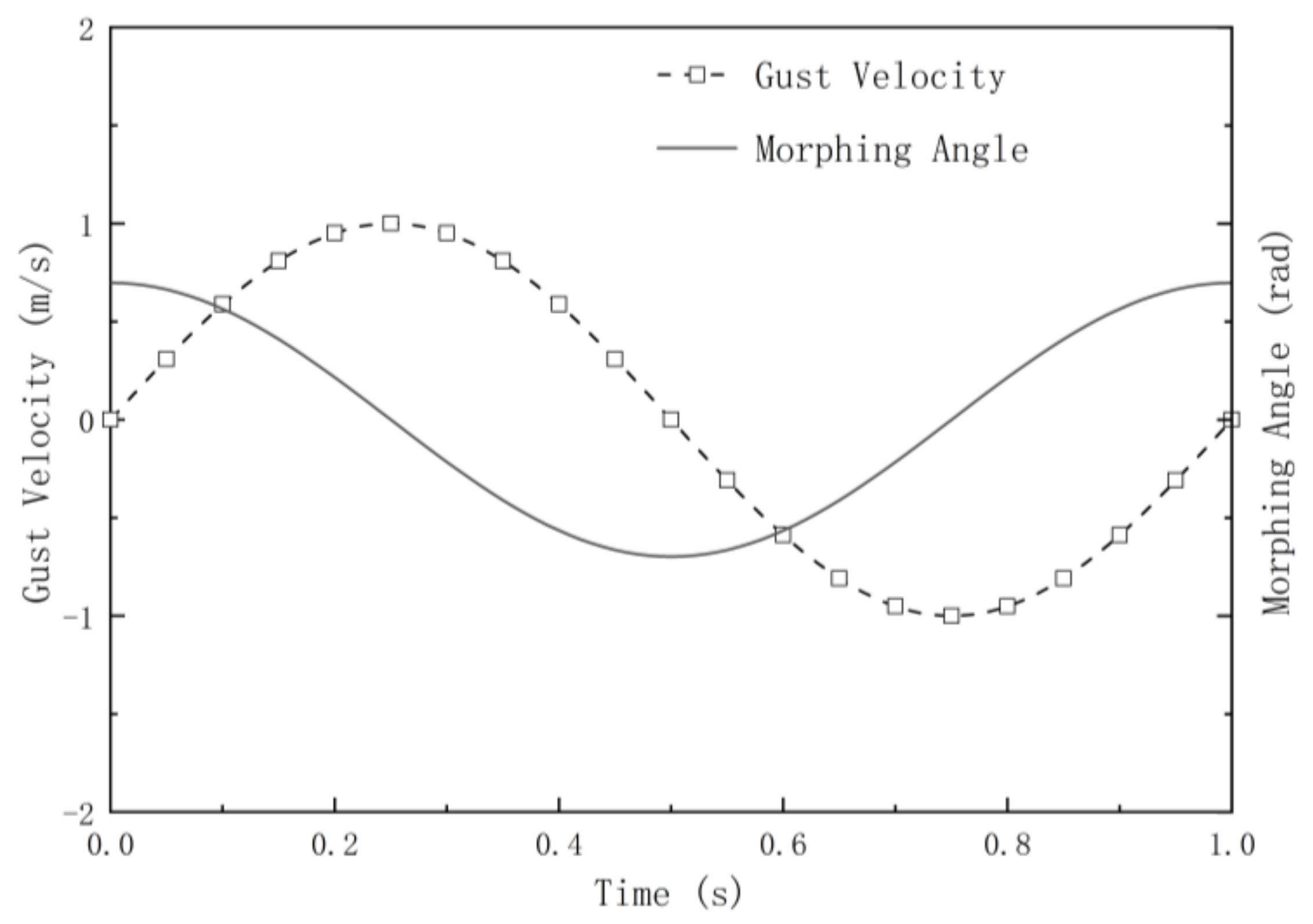
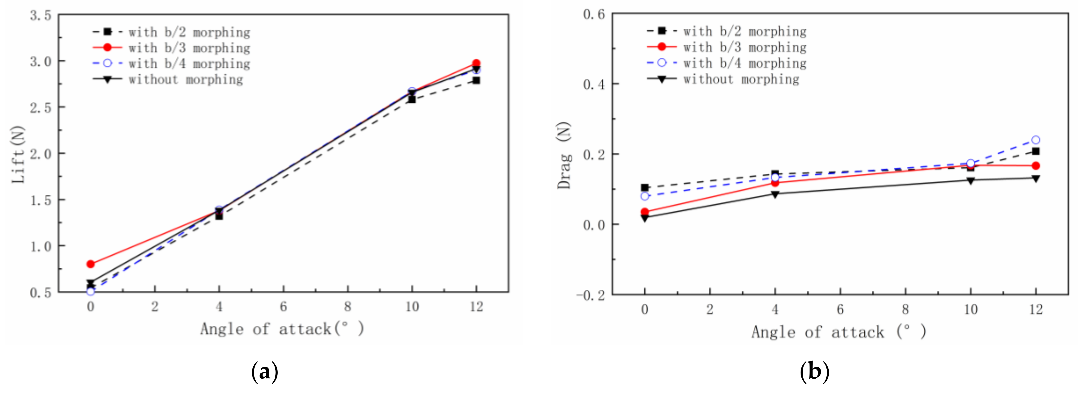
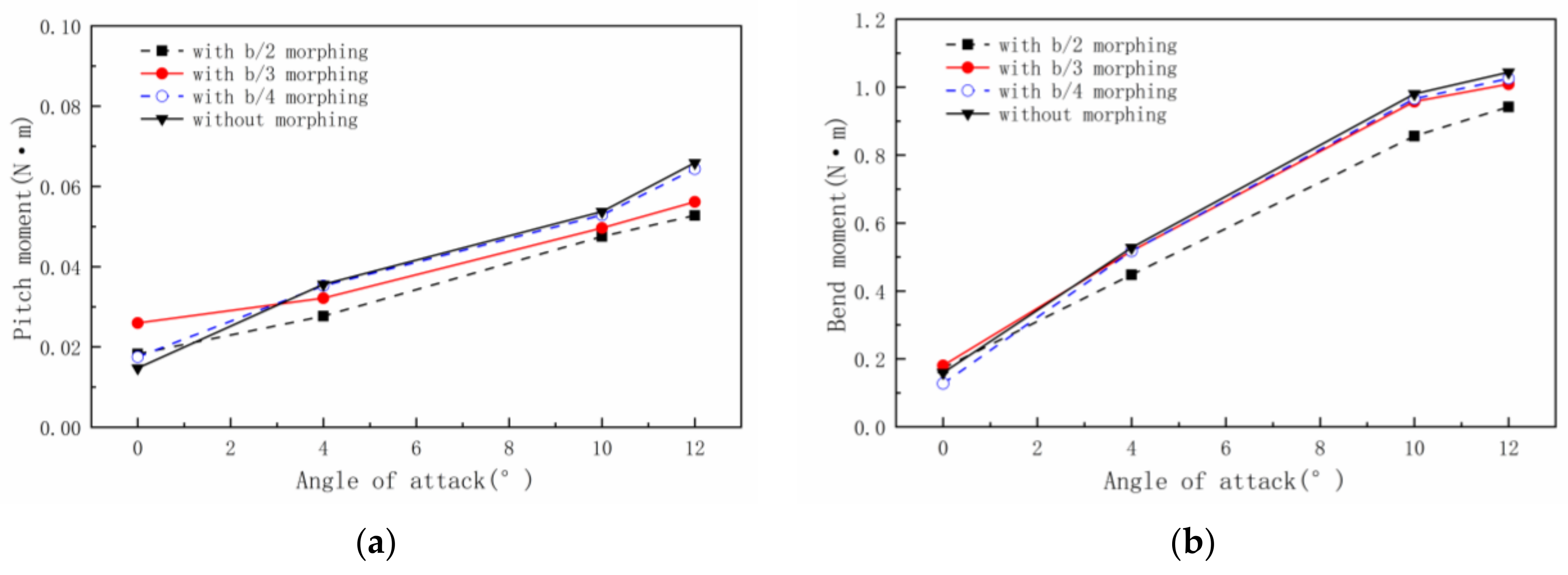
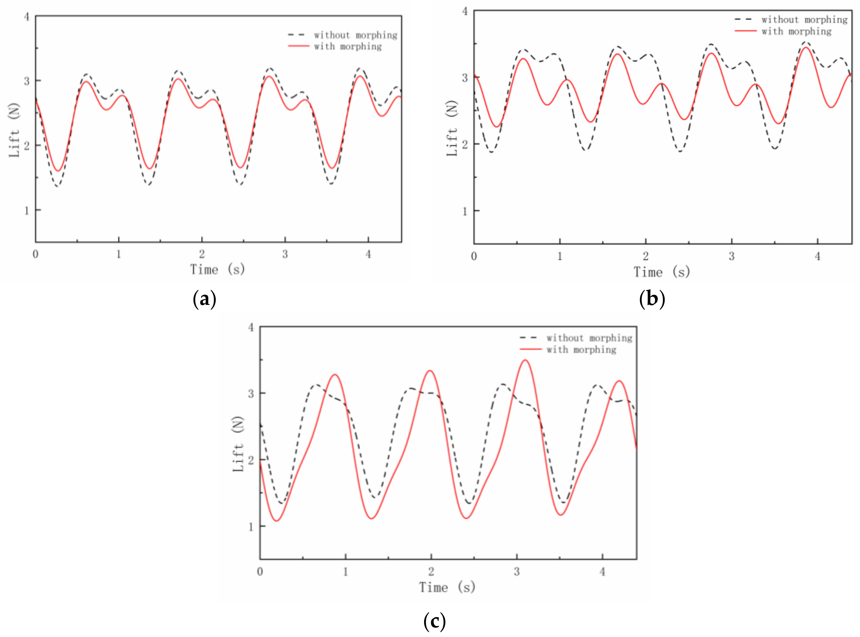
3.1.1. The Gust Frequency Is Equal to the Morphing Frequency

Firstly, the lift force, drag force, bend moment and pitch moment of the b/2, b/3 and b/4 morphing part length models at different AOAs are compared under a G1 gust. Figure 12a shows the lift forces of different wing models at different AOAs. It can be seen that the lift force of the spanwise morphing wing with the morphing part lengths of b/3 and b/4 is significantly compensated. The larger the length of the morphing part, the more obvious the increase in the lift force is. Moreover, when the length of the morphing part is b/3 and the AOAs are 0°, 4°, 10° and 12°, the lift force increases by 5.1%, 40%, 22.2% and 12.4%, respectively. However, when the morphing part length is b/2, it is so large that a vibration phenomenon occurs in the wing model, especially in the case of a large AOA. Therefore, the lift force of this case is even smaller than the gust response value. Figure 12b shows the variation in the drag forces of different morphing lengths at different AOAs. Due to flapping at the wing tip, the wind area of the morphing wing becomes larger and the drag force increases significantly in the whole process of movement. Moreover, the larger the morphing part and AOA are, the larger the drag force is. It can be seen that the wing with a b/3 morphing part length has greater lift than the wing with a b/2 morphing part length, and greater drag than the wing with a b/4 morphing part length.
Figure 13 shows the variations of the bend moment and the pitch moment. Figure 13a shows the curve of the pitch moment with the AOA. It can be seen that the pitch moment decreases with the wing tip flapping. The pitch moment decreases more with the increase in the morphing part length. For the b/2 morphing part length, the pitch moment decreases by 4.3% and 10.6% at the AOAs of 10° and 12°, respectively. Figure 13b shows the curve of bend moment with the AOA. The positive value represents the tensile force on the lower surface. It can be seen that when the wing tip starts flapping, the bend moment is significantly reduced, which helps to ensure the wing’s structural safety and prevent damage from wind gusts. As the morphing part length increases, the bend moment decreases. For the b/2 morphing part length, the bend moment decreases by 17.1% and 14.1% at the AOAs of 10° and 12°, respectively.

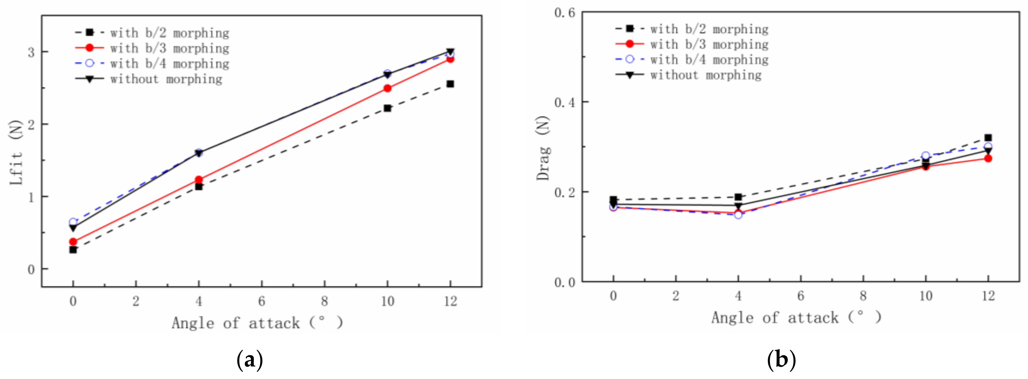
3.1.2. The Gust Frequency Is Different from the Morphing Frequency

For the condition that the gust frequency (2 Hz) is greater than the morphing frequency (1 Hz), the variation law of force and moment is analyzed. Figure 14 shows the lift and drag forces of different wing models at different AOAs. For the lift force variation in Figure 14a, when the morphing frequency is less than the gust frequency, the lift force of the wing is very close to that of the gust response. For the drag force variation in Figure 14b, it can be seen that the drag force of the spanwise morphing wing increases slightly compared with the gust response.
Figure 15 shows the variations in the bend moment and the pitch moment. Figure 15a shows the curve of the pitch moment with the AOA. It can be seen that the pitch moment decreases as the wing tip starts flapping, except for the 0° AOA. Additionally, the larger of the morphing part, the more obvious the decrease. For the b/2 morphing part length, the pitch moment decreases by 3.0% and 4.4% at the AOAs of 10° and 12°, respectively. Figure 15b shows the curve of bend moment with the AOA. As shown in the figure, when the wing tip starts flapping, the bend moment decreases obviously. Additionally, the larger the morphing part, the smaller the bend moment. For the morphing part length of b/2, the pitch moment decreases by 12.6% and 9.8% at the AOAs of 10° and 12°, respectively.
Then, for the condition that the gust frequency (0.5 Hz) is less than the morphing frequency (1 Hz), the variation law of force and moment is analyzed. Figure 16a shows the variation of lift force with AOAs at different morphing part lengths. When the morphing frequency is greater than the gust frequency, the lift force of the wing is smaller than that of the gust response, and the lift force of the wing decreases with the increase in the morphing part length. Figure 16b shows that the drag force of the wing with the morphing part is close to the gust response result, and only the drag force of the wing with the b/2 morphing part length is slightly greater than the gust response result. Therefore, it can be concluded that when the gust frequency is less than the morphing frequency, the spanwise morphing wing makes it not only difficult to achieve the effect of gust alleviation, but also has the possibility of deterioration.
Figure 17a shows the variation curve of pitch moment with the AOA. It shows that the pitch moment decreases significantly when the AOA is large (such as 10° and 12°). The values of pitch moment and gust response of the wing in the b/3 morphing part length are very close. Figure 17b shows the variation curve of the bend moment with the AOA. As can be seen from the figure, with the movement of the morphing part, the bend moment of the wing becomes smaller. Additionally, still, the values of the pitch moment and the gust response of the wing in the b/3 morphing part length are very close.
To sum up, generally, when the morphing frequency is equal to the gust frequency, the spanwise morphing wing has a better aerodynamic performance. When the morphing frequency is different from the gust frequency, the gust alleviation effect is not obvious, and may even lead to the deterioration of aerodynamic performance.

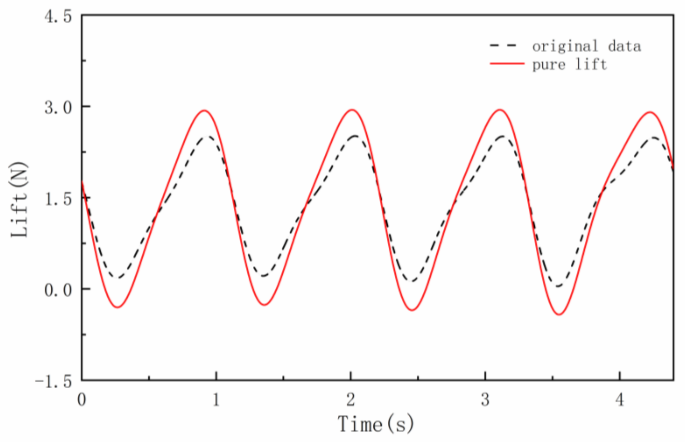
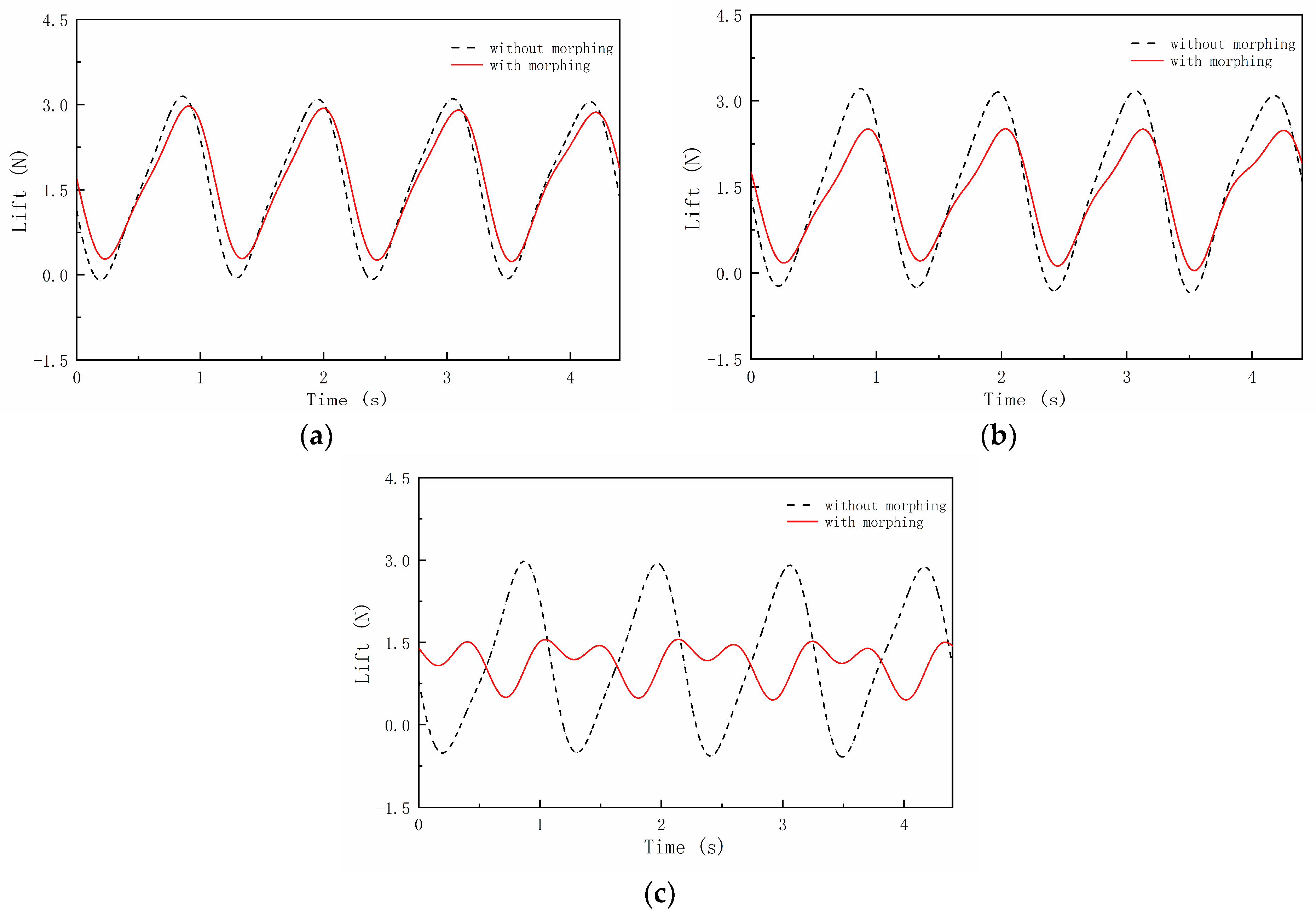
3.2. Gust Alleviation Effect of Instantaneous Lift Force

In this part, the gust alleviation effect of the three spanwise morphing wing models was analyzed in the case of the same gust frequency (1 Hz) and morphing frequency (1 Hz). The AOAs of 4° and 10° were selected as examples to analyze the gust alleviation effect by instantaneous lift force. The gust alleviation effect can be concluded from the reduction in the amplitude change of the instantaneous lift force.
Figure 18 compares the lift gust response (without morphing) and gust alleviation effect (with morphing) at a small AOA (4°). Figure 18a shows the comparison results of the wing with a b/4 morphing part length. It can be seen that since the morphing part is relatively small, the instantaneous lift force of gust response and gust alleviation is close. When the length of the morphing part increases to b/3, as shown in Figure 18b, the instantaneous lift force of gust alleviation is less than that of the gust response, which can effectively reduce the pitch angle variation and improve flight stability. When the length of the morphing part increases to b/2, as shown in Figure 18c, due to the large size of the morphing part, the overload of the wing significantly decreases during the whole process. Additionally, the instantaneous lift force of the gust alleviation within a period is divided into two parts. In the first part, the wing’s lift force goes through a period similar to the sine function, and its average value is also larger. In the second part, the variation of the instantaneous lift force is consistent with that of the first part, but its average value decreases significantly.
Figure 19 compares the lift gust response and gust alleviation effect at a large AOA (10°). Since the critical AOA of the wing is also 10°, the gust response is no longer a regular sinusoidal shape. Figure 19a shows the comparison result of the wing with a b/4 morphing part length. It can be seen that the instantaneous lift force value and frequency are almost the same. Figure 19b shows the comparison result of the b/3 morphing part length. The frequencies and the instantaneous lift force variation trend of the two conditions are basically the same. However, when the morphing part flaps downward, the lift force is greatly eased. When the length of the morphing part increases to b/2, as shown in Figure 19c, the frequency of gust response and gust alleviation is still consistent, but the instantaneous lift force value of gust alleviation is greater than that of the gust response. Therefore, at the critical AOA, the spanwise morphing wing with a b/3 morphing part length is better and neither lacks adjustment ability nor has overshoot problems.

3.3. Numerical Results and Analysis

In this part, a numerical simulation is carried out to reveal the aerodynamic mechanics of the spanwise morphing wing in a gusty environment. This section focuses on the comparison of the aerodynamic characteristics of the spanwise morphing wing when the gust is G1, the incoming flow velocity is 11 m/s, the morphing part length is b/3, the morphing frequency is 1 Hz and the flapping amplitude is 40°.

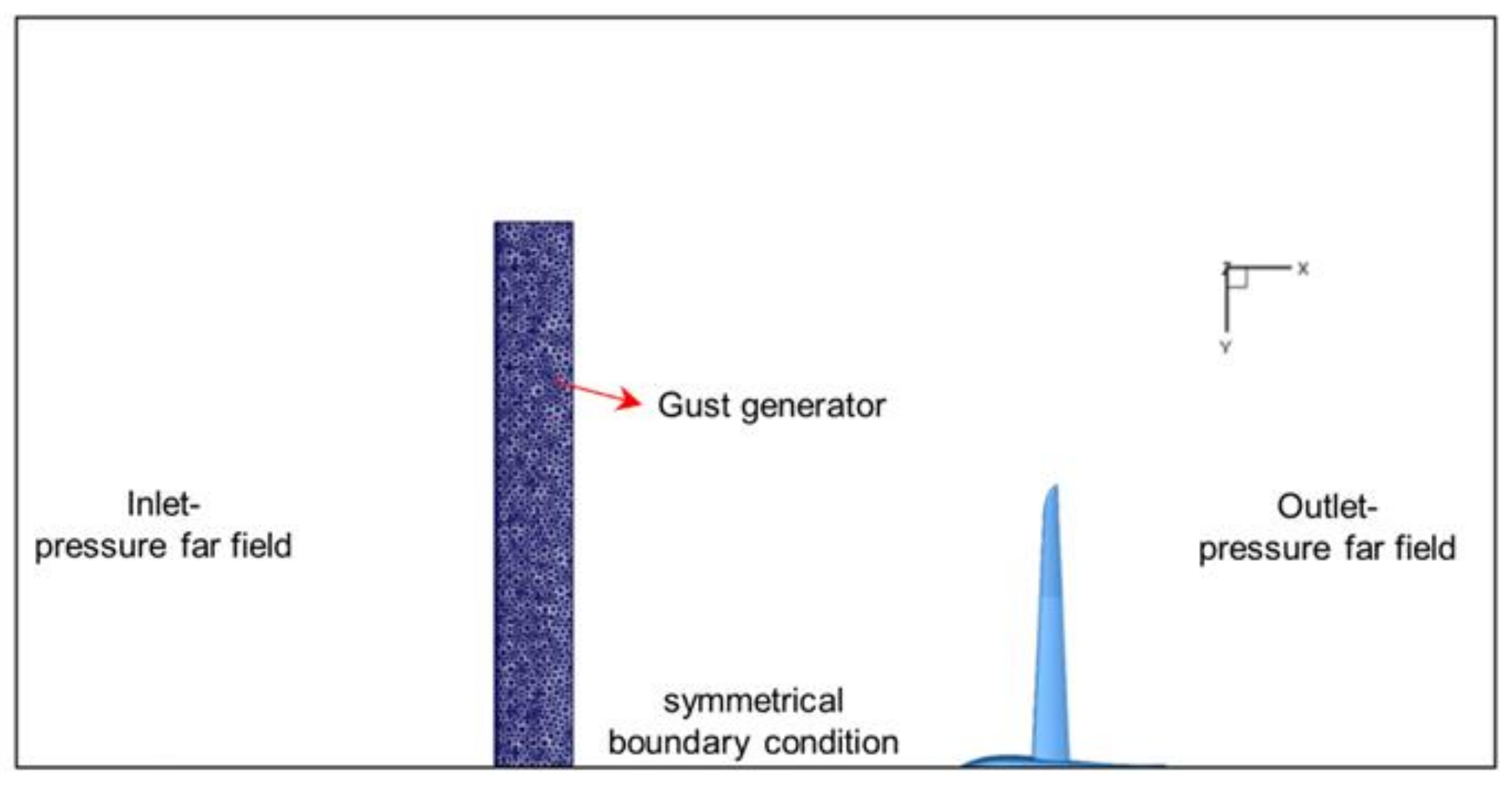
3.3.1. Numerical Simulation Model

To analyze the aerodynamic mechanism of the spanwise morphing wing in the gust environment, a three-dimensional wing segment is set in front of the numerical wing model according to the wind tunnel test to simulate the gust generator. The numerical simulation model is shown in Figure 20. The CFD simulations are carried out by Ansys Fluent v18.2. In the simulation scheme, the turbulence model is chosen as the Spalart–Allmaras model and the unsteady incompressible RANS equations are solved by the finite-volume method. A second-order upwind scheme is used for convection terms. A second-order central difference scheme is used for diffusion terms. The SIMPLE algorithm is used for pressure–velocity coupling. The flapping of the wingtip is achieved by adopting the dynamic mesh combined with user-defined functions. Based on the movement law of the flapping wingtip, the morphing is realized by controlling the position of the grid nodes. The specific process is shown as follows:
θ = θ max × sin ( 2 π f ( t Δ t ) ) θ = θ max × sin ( 2 π f t )
r = ( y b ) / cos ( θ )
z = z + r × ( sin ( θ ) sin ( θ ) ) y = b b m + r × cos ( θ )
where y′ denotes the position of the node at the previous time, b denotes the half span, bm denotes the length of the morphing part, θ denotes the morphing angle at the previous time and f denotes morphing frequency.
Through the above derivation, the position of each node at every moment is known, and with the change in the calculation time step, the wing morphing occurs simultaneously. Compared with the wind tunnel experiment results, the maximum errors of the average lift force of the CFD simulation results are within 10%, and the accuracy of the numerical simulation method has been proven in our previous work [11]. In this paper, the purpose of the CFD analysis is to reveal the aerodynamic mechanism qualitatively, whereas the quantitative analysis is presented in the wind tunnel experiment result.
In the calculation process, the phase difference between gust velocity and wing morphing is not considered. The motion law of the gust generator and the spanwise morphing wing are set, respectively. According to the distance between these two, the start time of wing morphing is set to ensure that the phase difference between gust velocity and wing movement is 0.

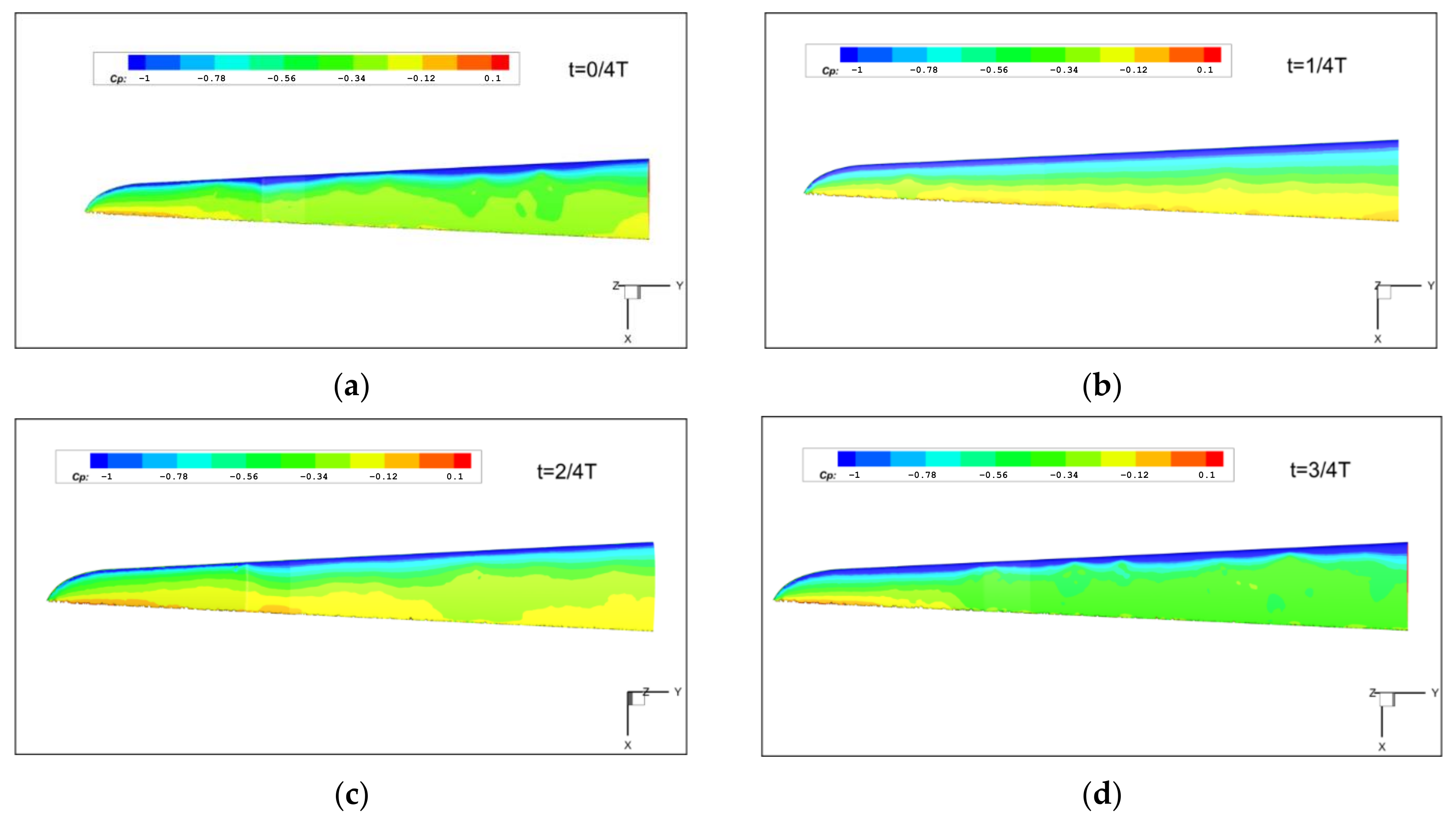
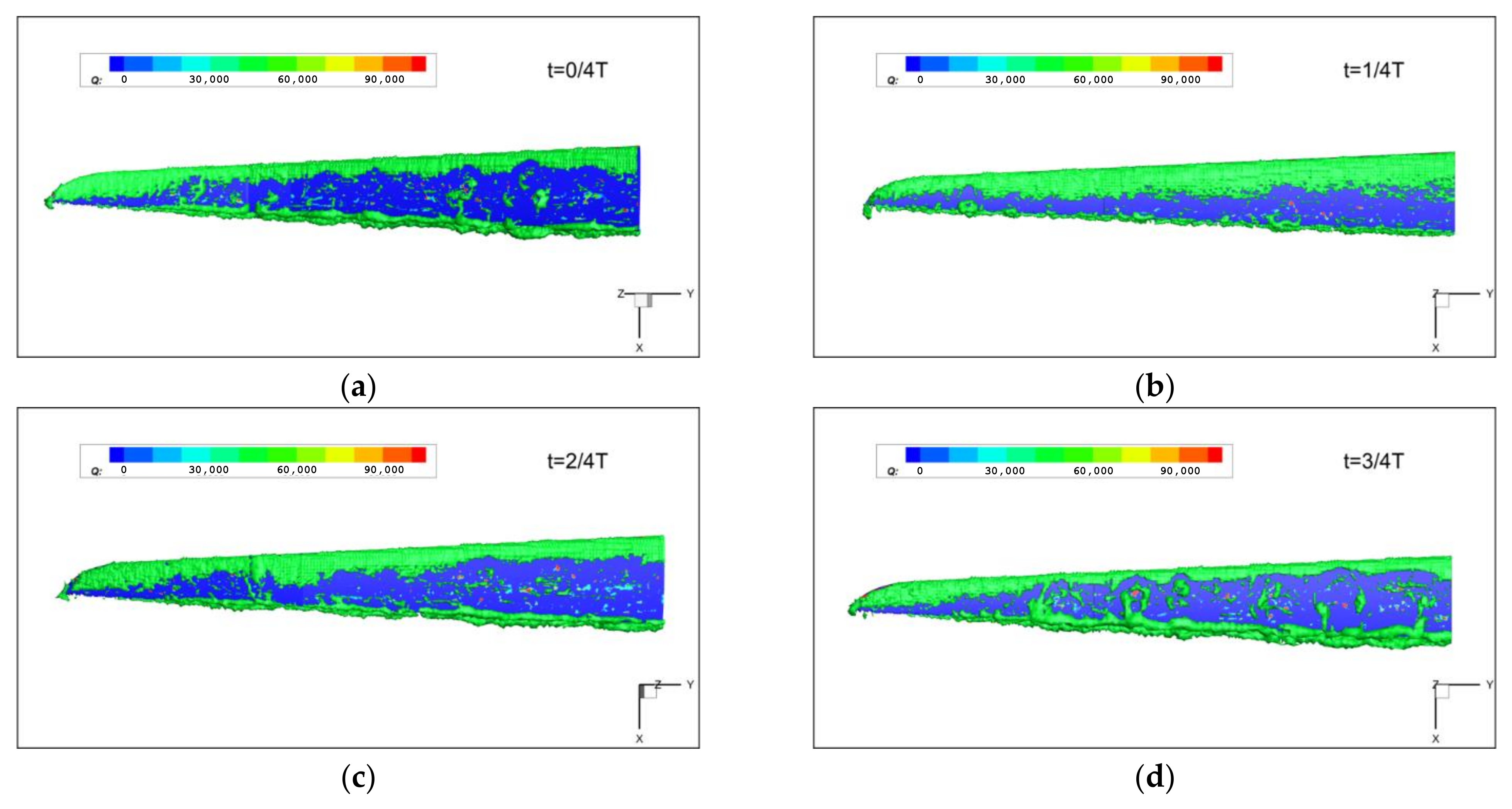
3.3.2. Pressure and Flow Field Analysis

In this section, the distribution of pressure and flow field of the spanwise morphing wing at different moments are extracted to analyze the flow mechanism. Firstly, four typical moments are extracted: the time of 0/4 T, which is the physical time of 0 s, the morphing part flaps upward to the maximum; the time of 1/4 T, which is the physical time of 0.25 s, the morphing part flaps downward to the equilibrium position; the time of 2/4 T, which is the physical time of 0.5 s, the morphing part flaps downward to the maximum; the time of 3/4 T, which is the physical time of 0.75 s, the morphing part flaps upward to the equilibrium position.
Figure 21 and Figure 22 show the pressure coefficient and vortex structure distribution of the spanwise morphing part, respectively. From the distribution of the pressure coefficient, the upper surface pressure at the time of 2/4 T is the maximum, and the lift force at this time is the minimum. At the time of 3/4 T, the pressure on the upper surface is the minimum, so the lift force is the maximum. In addition, the lift force of the spanwise morphing wing is mainly affected by the vortex structure distribution at the trailing edge of the wing. The trailing edge vortices at 3/4 T are larger than those at other times.
From the evolution of the pressure and vortex structure at each moment, it can be seen that in the downward flapping process (0/4 T–2/4 T), the flapping speed gradually decreases, and the lift force caused by the flapping also decreases during the process from 1/4 T to 2/4 T, whereas the lift loss caused by the morphing increases, so the lift force decreases to the minimum value. In the upward flapping process (2/4 T–3/4 T), the flapping speed and the lift force increase; meanwhile, the lift loss caused by the morphing decreases, so the lift force of the wing increases to the maximum. Compared with the gust response, during the morphing process, the morphing part flaps down/up, which increases/decreases the lift force. The upward flapping and downward flapping of the morphing part will simultaneously reduce the effective wing area and therefore reduce the lift force. The change in lift force comes from the combined effect of the two. Since the AOA is 10°, the local speed upward gust will further increase the AOA, causing it to face stalling. Therefore, the change in the vortex structure is more obvious, and the fluctuation of the lift force is more severe.

4. Conclusions

In this paper, the gust alleviation effect of the spanwise morphing wing is studied. The aerodynamic forces and moments of the spanwise morphing wing in the gust environment are analyzed through a wind tunnel test, thereby the influence of morphing parameters such as morphing frequency, morphing part length and AOA are studied. The flow mechanism of the spanwise morphing wing is analyzed through numerical simulation. The conclusions are as follows:
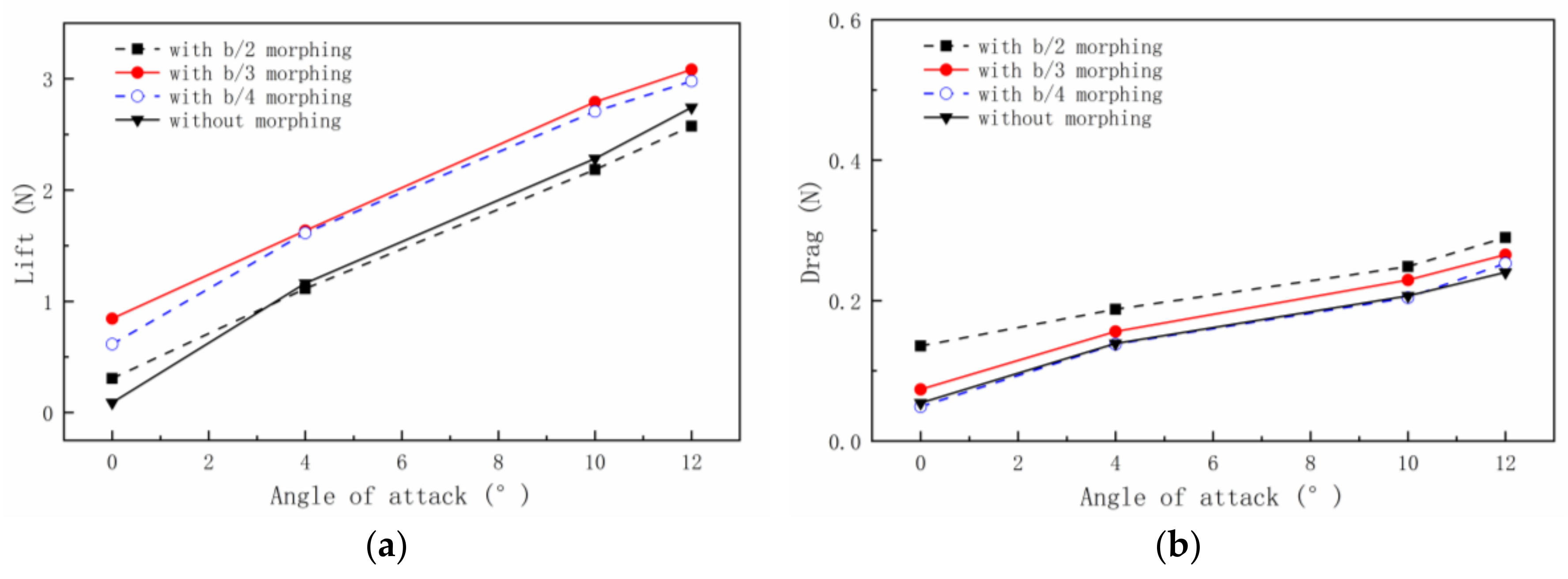
  • The wind tunnel results of the spanwise morphing wing show that when the gust frequency and morphing frequency are equal, the wing with a b/3 morphing part length has the greatest lift but also produces greater drag. When the gust frequency is greater than the morphing frequency, the lift force of the gust alleviation is very close to the lift force of the gust response, and the lift curves with different morphing part lengths cross with each other, but the drag forces all increase. When the gust frequency is less than the morphing frequency, the spanwise morphing wing not only faces difficulty in achieving the effect of gust alleviation but also has the possibility of deterioration.
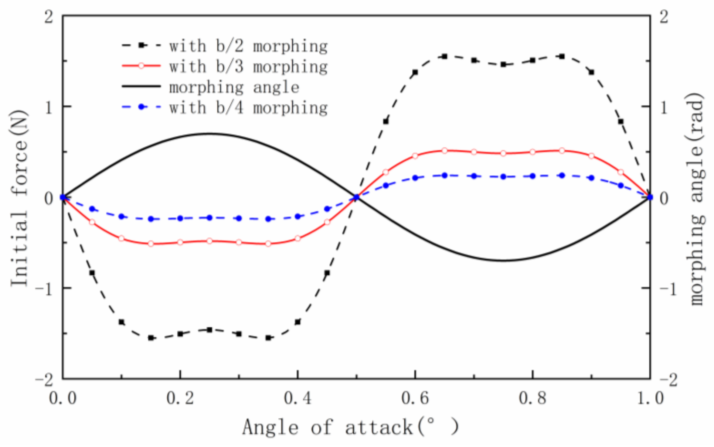
  • The results of the instantaneous lift force show that the lift fluctuation is more stable when the morphing part length is larger and the AOA is small. When the AOA is large, the appropriate morphing part length will also make the lift fluctuation stable. Therefore, the appropriate morphing part length can improve flight performance.
  • The numerical results show that from the distribution of the pressure coefficient and the change in the vortex structure, it can be seen that the lift force decreases to the minimum in the downward flapping process and increases to the maximum in the upward flapping process. The lift force variation of the spanwise morphing wing is mainly affected by the distribution of the vortex structure at the trailing edge of the wing. In the process of morphing, the morphing part flaps down/up, making the lift increase/decrease. The upward flapping and downward flapping of the wing will simultaneously reduce the effective area of the wing and reduce the lift force. The change in lift force comes from the combined effect of the two.
To sum up, from the above results, it can be concluded that when the morphing frequency is equal to the gust frequency, the spanwise morphing wing designed in this paper can effectively achieve gust alleviation. Moreover, the appropriate morphing part length can increase the average lift force in the gust environment and at the same time reduce the lift fluctuation of the wing, so that the flight of the aircraft will be more stable. The conclusions obtained in this paper can be useful guidance for the design of the morphing aircraft and significantly improve flight performance.

Author Contributions

Conceptualization, D.L. and Z.K.; Methodology, Z.K. and Z.Y.; Software, Z.K.; Validation, D.L., Z.K. and Z.Y.; Formal Analysis, Z.K.; Investigation, Z.Y.; Resources, D.L.; Data Curation, Z.K.; Writing—Original Draft Preparation, Z.K. and Z.Y.; Writing—Review & Editing, D.L., Z.K. and Z.Y.; Visualization, Z.K.; Supervision, D.L.; Project Administration, D.L.; Funding Acquisition, D.L. All authors have read and agreed to the published version of the manuscript.

Funding

This research was funded by the National Natural Science Foundation of China (Grant Number 11972059).

Institutional Review Board Statement

Not applicable.

Informed Consent Statement

Not applicable.

Data Availability Statement

Not applicable.

Conflicts of Interest

The authors declare no conflict of interest.

References

  1. Li, D.; Zhao, S.; Da Ronch, A.; Xiang, J.; Drofelnik, J.; Li, Y.; Zhang, L.; Wu, Y.; Kintscher, M.; Monner, H.P.; et al. A Review of Modelling and Analysis of Morphing Wings. Prog. Aerosp. Sci. 2018, 100, 46–62. [Google Scholar] [CrossRef] [Green Version]
  2. Li, Y.; Ge, W.; Zhou, J.; Zhang, Y.; Zhao, D.; Wang, Z.; Dong, D. Design and Experiment of Concentrated Flexibility-based Variable Camber Morphing Wing. Chin. J. Aeronaut. 2021, 5, 455–469. [Google Scholar] [CrossRef]
  3. Huang, R.; Zhou, X. Parameterized Fictitious Mode of Morphing Wing with Bilinear Hinge Stiffness. AIAA J. 2021, 59, 2641–2656. [Google Scholar] [CrossRef]
  4. Chen, Z.; Zhang, W.; Mou, J.; Zheng, K. Horizontal Take-off of an Insect-like FMAV based on Stroke Plane Modulation. Aircr. Eng. Aerosp. Technol. 2022, 94, 1068–1077. [Google Scholar] [CrossRef]
  5. Lee, S.-G.; Yang, H.-H.; Addo-Akoto, R.; Han, J.-H. Transition Flight Trajectory Optimization for a Flapping-Wing Micro Air Vehicle with Unsteady Vortex-Lattice Method. Aerospace 2022, 9, 660. [Google Scholar] [CrossRef]
  6. Carruthers, A.C.; Thomas, A.L.; Taylor, G.K. Automatic Aeroelastic Devices in the Wings of a Steppe Eagle Aquila Nipalensis. J. Exp. Biol. 2007, 210, 4136–4149. [Google Scholar] [CrossRef] [Green Version]
  7. Bie, D.; Li, D.; Xiang, J.; Li, H.; Kan, Z.; Sun, Y. Design, Aerodynamic Analysis and Test Flight of a Bat-Inspired Tailless Flapping Wing Unmanned Aerial Vehicle. Aerosp. Sci. Technol. 2021, 112, 106557. [Google Scholar] [CrossRef]
  8. Bie, D.; Li, D.; Li, H.; Kan, Z.; Tu, Z. Analytical Study on Lift Performance of a Bat-Inspired Foldable Flapping Wing: Effect of Wing Arrangement. Aerospace 2022, 9, 653. [Google Scholar] [CrossRef]
  9. Cheney, J.A.; Stevenson, J.P.; Durston, N.E.; Song, J.; Usherwood, J.R.; Bomphrey, R.J.; Windsor, S.P. Bird Wings Act as a Suspension System that Rejects Gusts. Proc. R. Soc. B Biol. Sci. 2020, 287, 20201748. [Google Scholar] [CrossRef]
  10. Richardson, P.L. How Do Albatrosses Fly Around the World without Flapping their Wings? Prog. Oceanogr. 2011, 88, 46–58. [Google Scholar] [CrossRef] [Green Version]
  11. Kan, Z.; Li, D.; Shen, T.; Xiang, J.; Zhang, L. Aerodynamic Characteristics of Morphing Wing with Flexible Leading-edge. Chin. J. Aeronaut. 2020, 33, 2610–2619. [Google Scholar] [CrossRef]
  12. Weisshaar, T.A. Morphing Aircraft Systems: Historical Perspectives and Future Challenges. J. Aircr. 2013, 50, 337–353. [Google Scholar] [CrossRef]
  13. Bashir, M.; Rajendran, P. Static Structural Analysis of a Variable Span Morphing Wing for Unmanned Aerial Vehicle. IOP Conf. Ser. Mater. Sci. Eng. 2018, 370, 012040. [Google Scholar] [CrossRef]
  14. Ajaj, R.M.; Saavedra Flores, E.I.; Friswell, M.I.; De la, O.F. Span Morphing Using the Compliant Spar. J. Aerosp. Eng. 2015, 28, 04014108. [Google Scholar] [CrossRef] [Green Version]
  15. Kan, Z.; Li, D.; Xiang, J.; Cheng, C. Delaying Stall of Morphing Wing by Periodic Trailing-Edge Deflection. Chin. J. Aeronaut. 2020, 33, 493–500. [Google Scholar] [CrossRef]
  16. Munday, P.M.; Taira, K.; Suwa, T.; Numata, D.; Asai, K. Nonlinear Lift on a Triangular Airfoil in Low-Reynolds Number Compressible Flow. J. Aircr. 2015, 52, 924–931. [Google Scholar] [CrossRef]
  17. Parancheerivilakkathil, M.S.; Haider, Z.; Ajaj, R.M.; Amoozgar, M. A Polymorphing Wing Capable of Span Extension and Variable Pitch. Aerospace 2022, 9, 205. [Google Scholar] [CrossRef]
  18. Boston, D.M.; Phillips, F.R.; Henry, T.C.; Arrieta, A.F. Spanwise Wing Morphing Using Multistable Cellular Metastructures. Extrem. Mech. Lett. 2022, 53, 101706. [Google Scholar] [CrossRef]
  19. Ajaj, R.M.; Friswell, M.I.; Bourchak, M.; Harasani, W. Span Morphing Using the GNATSpar Wing. Aerosp. Sci. Technol. 2016, 53, 38–46. [Google Scholar] [CrossRef] [Green Version]
  20. Ajaj, R.M.; Jankee, G.K. The Transformer Aircraft: A Multimission Unmanned Aerial Vehicle Capable of Symmetric and Asymmetric Span Morphing. Aerosp. Sci. Technol. 2018, 76, 512–522. [Google Scholar] [CrossRef] [Green Version]
  21. Yang, C.; Qiu, Q.; Zhou, Y.; Wu, Z. Review of Aircraft Gust Alleviation Technology. Act Aeronaut. Astronaut. Sin. 2022, 43, 527350. [Google Scholar]
  22. Cheung, R.C.; Rezgui, D.; Cooper, J.E.; Wilson, T. Testing of Folding Wingtip for Gust Load Alleviation of Flexible High-Aspect-Ratio Wing. J. Aircr. 2020, 57, 876–888. [Google Scholar] [CrossRef]
  23. Szczyglowski, C.P.; Neild, S.A.; Titurus, B.; Jiang, J.Z.; Coetzee, E. Passive Gust Loads Alleviation in a Truss-Braced Wing Using an Inerter-Based Device. J. Aircr. 2019, 56, 2260–2271. [Google Scholar] [CrossRef]
  24. Welstead, J.; Crouse, G.L. Segmented-Freewing Concept for Gust Alleviation. J. Aircr. 2015, 47, 1047–1059. [Google Scholar] [CrossRef]
  25. He, S.; Guo, S.; Liu, Y.; Luo, W. Passive Gust Alleviation of a Flying-wing Aircraft by Analysis and Wind-tunnel Test of a Scaled Model in Dynamic Similarity. Aerosp. Sci. Technol. 2021, 113, 106689. [Google Scholar] [CrossRef]
  26. Chowdhury, J.; Ringuette, M.J. Effect of a Rotating and Swept Wingtip on Streamwise Gust Alleviation. AIAA J. 2021, 59, 1–12. [Google Scholar] [CrossRef]
  27. Cheung, R.C.; Rezgui, D.; Cooper, J.E.; Wilson, T. Testing of a Hinged Wingtip Device for Gust Loads Alleviation. J. Aircr. 2018, 55, 2050–2067. [Google Scholar] [CrossRef]
  28. Castrichini, A.; Hodigere Siddaramaiah, V.; Calderon, D.E.; Cooper, J.E.; Wilson, T.; Lemmens, Y. Nonlinear Folding Wing Tips for Gust Loads Alleviation. J. Aircr. 2016, 53, 1391–1399. [Google Scholar] [CrossRef] [Green Version]
  29. Guo, S.; Jing, Z.W.; Li, H.; Lei, W.T.; He, Y.Y. Gust Response and Body Freedom Flutter of a Flying-wing Aircraft with a Passive Gust Alleviation Device. Aerosp. Sci. Technol. 2017, 70, 277–285. [Google Scholar] [CrossRef] [Green Version]
  30. Guo, S.; De Los Monteros, J.E.; Liu, Y. Gust Alleviation of a Large Aircraft with a Passive Twist Wingtip. Aerospace 2015, 2, 135–154. [Google Scholar] [CrossRef] [Green Version]
Figure 1. Comparison of three spanwise morphing wings.
Aerospace 10 00328 g001
Figure 2. The system of gust generator and control structure diagram.
Aerospace 10 00328 g002
Figure 3. (a) The wing model and (b) the gust generator installed on the tunnel.
Aerospace 10 00328 g003
Figure 4. Curves of morphing angle and gust velocity.
Aerospace 10 00328 g004
Figure 5. Comparison between Fourier filtering data and original data.
Aerospace 10 00328 g005
Figure 6. Diagram of inertial force in the morphing part.
Aerospace 10 00328 g006
Figure 7. Theoretical calculation of inertial force and spanwise morphing angle.
Aerospace 10 00328 g007
Figure 8. Comparison between the original data and the pure aerodynamic lift force (morphing part length b/3, AOA 4°).
Aerospace 10 00328 g008
Figure 9. Comparisons of lift/drag coefficients with different morphing part lengths.
Aerospace 10 00328 g009
Figure 10. Comparisons of lift/drag coefficients with flapping amplitude.
Aerospace 10 00328 g010
Figure 11. Comparisons of lift/drag coefficients with morphing frequency.
Aerospace 10 00328 g011
Figure 12. (a) Lift force and (b) drag force of different wing models at different AOAs.
Aerospace 10 00328 g012
Figure 13. (a) Pitch moment and (b) bend moment of different wing models at different AOAs.
Aerospace 10 00328 g013
Figure 14. (a) Lift force and (b) drag force of different wing models at different AOAs.
Aerospace 10 00328 g014
Figure 15. (a) Pitch moment and (b) bend moment of different wing models at different AOAs.
Aerospace 10 00328 g015
Figure 16. (a) Lift force and (b) drag force of different wing models at different AOAs.
Aerospace 10 00328 g016
Figure 17. (a) Pitch moment and (b) bend moment of different wing models at different AOAs.
Aerospace 10 00328 g017
Figure 18. Lift force variation of different morphing part lengths at 4° AOA. (a) b/4 morphing part length, (b) b/3 morphing part length and (c) b/2 morphing part length.
Aerospace 10 00328 g018
Figure 19. Lift force variation of different morphing part lengths at 10° AOA. (a) b/4 morphing part length, (b) b/3 morphing part length and (c) b/2 morphing part length.
Aerospace 10 00328 g019
Figure 20. Simulation model.
Aerospace 10 00328 g020
Figure 21. Pressure distribution of spanwise morphing wing at 10° AOA. (a) Time of 0/4 T, (b) time of 1/4 T, (c) time of 2/4 T and (d) time of 3/4 T.
Aerospace 10 00328 g021
Figure 22. Q criterion of spanwise morphing wing at 10°AOA (Q = 50,000). (a) Time of 0/4 T, (b) time of 1/4 T, (c) time of 2/4 T and (d) time of 3/4 T.
Aerospace 10 00328 g022
Table 1. Test parameters.
Morphing Part LengthAngle of AttackGust ModelMorphing Parameters
b/2G1(deflection frequency 1 Hz)Frequency: 1 Hz
Amplitude: 40°
b/3G2(deflection frequency 0.5 Hz)
10°
b/412°G3(deflection frequency 2 Hz)
Table 2. Parameters corresponding to different morphing part lengths.
Morphing Part LengthWeight m (g)Distance to the Rotation Axis r (mm)
b/255.38127.5
b/327.3185.4
b/417.0863.9
Disclaimer/Publisher’s Note: The statements, opinions and data contained in all publications are solely those of the individual author(s) and contributor(s) and not of MDPI and/or the editor(s). MDPI and/or the editor(s) disclaim responsibility for any injury to people or property resulting from any ideas, methods, instructions or products referred to in the content.

