Article

Experimental Study on the Propagation Characteristics of Rotating Detonation Wave with Liquid Hydrocarbon/High-Enthalpy Air Mixture

1
Department of Aerospace Science and Technology, Space Engineering University, Beijing 101416, China
2
Beijing Power Machinery Institute, Beijing 100074, China
*
Author to whom correspondence should be addressed.
Aerospace 2023, 10(8), 682; https://doi.org/10.3390/aerospace10080682
Submission received: 25 March 2023 / Revised: 16 July 2023 / Accepted: 27 July 2023 / Published: 31 July 2023

Abstract

:
Rotating detonation engines (RDEs) are a promising propulsion technology featuring high thermal efficiency and a simple structure. To adapt the practical engineering applications of ramjet RDEs, rotating detonation combustion using a liquid hydrocarbon and pure air mixture will be required. This paper presents an experimental study on the propagation characteristics of rotating detonation waves with a liquid hydrocarbon and high-enthalpy air mixture in a hollow cylindrical chamber. The parameters, such as the equivalence ratio and inlet mass flux, are considered in this experiment. The frequency and the propagation velocity of rotating detonation combustion are analyzed under typical operations. The experimental results show that the peak pressure and propagation velocity of the rotating detonation wave are close to the C-J theoretical values under the inlet mass flux of 400 kg/(m2s). Both the propagation velocity and peak pressure of the rotating detonation wave decrease as the mass flux and equivalence ratio are reduced while the number of detonation wavefronts increases. Detonation wave instability tends to occur when the inlet mass flux decreases. There is a transition progress from thermo-acoustic combustion to rotating detonation combustion in the experiment under the condition of mass flux 350 kg/(m2s) and the equivalent ratio 0.8. The static pressure in the chamber is higher during detonation combustion than during thermo-acoustic combustion. These experimental results provide evidence that rotating detonation waves have the potential to significantly improve propulsion performance. The findings can serve as a valuable reference for the practical engineering application of rotating detonation engines.

1. Introduction

Combustion processes occur in two primary modes: deflagration and detonation. Deflagration wave propagation depends on the mass and heat transfer of the combustible mixtures, which travel at subsonic speeds, leading to a constant pressure combustion mode. In contrast, detonation waves propagate at supersonic speeds, facilitating self-ignition combustion behind the leading shock, and this characteristic aligns detonation closely with constant volume combustion. While the majority of current chemical aerospace propulsion systems operate using a constant pressure combustion cycle, enhancing their performance has become an increasingly challenging task. Due to its high thermal efficiency, detonation engines present a novel concept that holds promise for improving engine performance. There are various types of detonation engines, including pulsed detonation engines (PDEs) [1,2], rotating detonation engines (RDEs) [3,4], oblique detonation engines (ODEs) [5,6,7], and detonation hybrid engines [8,9].
Rotating detonation engines (RDEs) have garnered significant attention and have been the focus of extensive research by scientists worldwide. Earlier studies have successfully observed rotating detonation waves in annular combustion chambers, providing further evidence for the feasibility of RDEs [10,11]. Additionally, Tang et al. [12] conducted numerical simulations demonstrating the continuous rotation of detonation waves within a hollow RDE combustion chamber. Almost simultaneously, researchers [13,14] successfully demonstrated the experimental realization of a stable rotating detonation wave in a cylindrical rotating detonation engine (RDE) [15]. Rodriguez et al. [16] conducted an experiment using a curved chamber without a center body and observed the propagation of multicellular detonation at velocities higher than the Chapman–Jouguet (C–J) value. They found that the overdriven detonation occurred due to the irregular reflection of the initially oblique front as the outer wall tilted in relation to the front. Yokoo, R. et al. [17] conducted an experimental study confirming that the length of a cylindrical rotating detonation chamber can be shorter compared to an annular rotating detonation chamber. By removing the inner tube, a more compact rotating detonation chamber was achieved, resulting in a smaller thermal protection area. This advantage holds significant potential for the engineering application of rotating detonation engines. Therefore, this study focuses on investigating rotating detonation combustion within a hollow chamber.
Rotating detonation combustion has predominantly been studied in the context of rocket-type engines. However, there is a growing interest among researchers worldwide in the ram-mode detonation engine. This type of engine, designed for air-breathing applications, has gained significant attention. Cycle analysis of the air-breathing detonation ramjet model has been reported, examining its performance and characteristics [18]. This study revealed that the performance of the air-breathing detonation ramjet gradually decreases as the flight speed increases. However, it demonstrated that achieving a flight Mach number of Ma 5 is feasible within the capabilities of the engine. Frolov, S. M. et al. [19] conducted experiments using an air-stream approach with a Mach number of 5.7. The ramjet model achieved maximum thrust and specific impulse values at an equivalence ratio (ER) of 1.25. The thrust was estimated to be 1550 N, while the specific impulse was measured at 3300 s. Liu et al. [20] designed a continuous rotating detonation ramjet model engine specifically for a free jet test with a flight Mach number of 4.5 and an altitude of 18.5 km. Hydrogen was utilized as the fuel in this design, and the maximum fuel-based specific impulse achieved was 2510 s, despite using an unoptimized nozzle configuration. These findings suggest that the ram-mode rotating detonation engine holds significant promise for engineering applications.
In RDEs, gaseous fuels are frequently employed. Researchers have conducted investigations [21,22,23,24,25,26] on the effects of several factors on rotating detonation wave characteristics and have made efforts to control the propagation mode of rotating detonation. These factors include propellant mass flow rate, chamber outlet pressure, propellant pressure loss, and nozzle structure. Fuels such as acetylene, propane, and hydrogen have been utilized in these studies. Recently, there has been increasing interest in heterogeneous rotating detonation. Researchers have implemented various measures to achieve heterogeneous rotating detonation, including the use of oxygen-enriched air [27,28], heated air [29,30,31], and a mixture of kerosene/highly active fuels [32,33,34]. In addition, Le Naour et al. [35] utilized a fuel mixture of hydrogen and kerosene. However, when the liquid hydrocarbon fuel was injected separately, the propagation velocity of the detonation wave decreased significantly. This suggests that the specific fuel injection method can have a significant impact on the characteristics and behavior of the rotating detonation wave in heterogeneous systems. Researchers investigated the impact of periodic detonation wave impact on a liquid fuel jet in a rotating detonation combustor and obtained the dynamic response and recovery of liquid jets exposed to periodic detonations [36,37,38].
In consideration of factors such as fuel transportation and storage security, space constraints of flight vehicles, and the specific impulse performance requirements of the engine, the practical implementation of a ramjet RDE in engineering applications often involves optimizing liquid hydrocarbon as the fuel and using pure air as the oxidizer. Modern hypersonic aircraft typically operate at altitudes ranging from 30 to 100 km and Mach numbers ranging from 5 to 30. The ramjet rotating detonation engine holds potential as a propulsion system for hypersonic aircraft. Therefore, this study focuses on assessing the feasibility of rotating detonation combustion using a mixture of liquid hydrocarbon fuel and high-enthalpy air, where the total temperature exceeds the incoming flow temperature at a Mach number above Ma5 (1250 K).
The presence of deflagration within the rotating detonation chamber has a substantial effect on the behavior of the rotating detonation wave. The deflagration process contributes to the weakening of the detonation front and, from a thermodynamic perspective, reduces the cycle efficiency [39]. As more propellant is consumed by deflagration, less propellant remains to support the detonation wave. Furthermore, deflagration raises the temperature of the mixture ahead of the detonation wave, increasing the effective speed of sound and decreasing the detonation wave Mach number [40]. Researchers have examined the impact of the wall curvature and deflagrative losses. Their findings indicate that the detonation wave propagation velocity is lower than the C-J value in the non-premixed or premixed rotating detonation combustors [41,42]. The study investigates the effects of equivalence ratio and inlet mass flux on the propagation characteristics of the rotating detonation wave. The results of this investigation can offer valuable insights into the practical application of rotating detonation engines.
The non-ideal nature of the detonation wave significantly impacts the performance of rotating detonation engines. This paper presents an experimental study on the rotating detonation characteristics using a mixture of liquid hydrocarbon and high-enthalpy air. The research is conducted on a direct-connected experimental system, which is a common method for studying air-breathing rotating detonation engines. The experiments aim to understand the influence of incoming mass flux and equivalence ratio on the propagation characteristics of the rotating detonation wave. During the experiments, several unusual phenomena were observed, including the superposition of rotating detonation waves, pressure axial oscillation between the inlet and nozzle throat, and the transition between thermo-acoustic combustion and rotating detonation combustion. It is worth noting that the transition from thermo-acoustic combustion to detonation combustion occurred only once in the experiment, making it difficult to accurately explain the observed phenomena. The chamber was equipped with PCB pressure sensors and static pressure sensors, which limited the precision of the observations. Nevertheless, significant static pressure changes were observed in the combustion chamber when the transition from thermo-acoustic combustion to detonation combustion occurred under constant incoming flow conditions. The study also observed phenomena such as single-wave rotating detonation, co-directional double-wave, collision double-wave, and the superposition of pressure wave axial oscillation and the detonation wave in the combustion chamber. The research aims to establish the correlation between the occurrence of different combustion modes and the incoming flow conditions within the rotating detonation chamber.

2. Experimental Facilities

The geometry structure and the three-dimensional model of the experimental facility for rotating detonation employed in this study are illustrated in Figure 1 and Figure 2, respectively. The experimental system comprises four main components: the supply system, control system, measurement system, and engine model. The supply system encompasses an air source, fuel supply, electromagnetic valve, and various piping accessories. The high-temperature incoming flow of 1250 K used in the experiment is provided by the three-component (kerosene/air/oxygen) vitiator, and the mass flow rate is adjusted within the range of 3 kg/s to 6 kg/s.
The air and oxygen mix and flow into the vitiator through a small throat, and there are 30 centrifugal nozzles installed on the spray panel to maintain the kerosene atomizing well. The high-enthalpy air retains the same mass fraction as pure air. The nozzles of the detonation chamber are direct injection nozzles at the entrance throat, the number of spray holes is 120 inside and outside of the throat, respectively, and the diameter of the spray holes is 0.3 mm. The inner and outer diameters of the entrance throat of the chamber are 250 mm and 284 mm, respectively; the length of the detonation chamber is 490 mm, and the radius of the nozzle throat is 170 mm. Therefore, the inlet throat area of the combustion chamber is 14,260 mm2, and the nozzle throat area is 22,698 mm2. In the experiment, the inlet mass flux of the chamber is adjusted by the different mass flow rates of the vitiator components, but the temperature remains unchanged.
A pre-detonation tube igniter is used for ignition within the combustion chamber. If the mixture and combustion chamber structure conditions are suitable, rotating detonation combustion can be initiated. Factors such as the high total temperature of incoming air and high airflow speed at the fuel injection position contribute to improved atomization and evaporation of kerosene. As the fuel/air mixture flows to the engine’s ignition position, it transitions to a gaseous phase, which is one of the key factors for initiating and sustaining a pure air/kerosene rotating detonation wave. The dynamic pressure data in the combustion chamber are collected via an acquisition system with 16 parallel channels, and an acquisition frequency of 2.5 MHz. The pressure peak of the rotating detonation wave is measured by PCB113B26 quartz dynamic pressure sensor. There are three dynamic pressure sensors installed on the wall of the detonation chamber, as shown in Figure 1. The sensors PCB1 and PCB3 are distributed at a 90-degree angle in the same section of the chamber wall. The sensor PCB2 is set downstream of PCB1. The static pressure data in the combustion chamber is collected by an acquisition system of frequency 100 Hz.

3. Results and Discussion

The total temperature of the incoming flow is maintained constant at 1250 K. The test conditions are presented in Table 1. Considering the practical engineering applications of ramjet RDEs, all tests are conducted under lean mixture conditions, with an equivalence ratio ranging from 0.5 to 0.8.

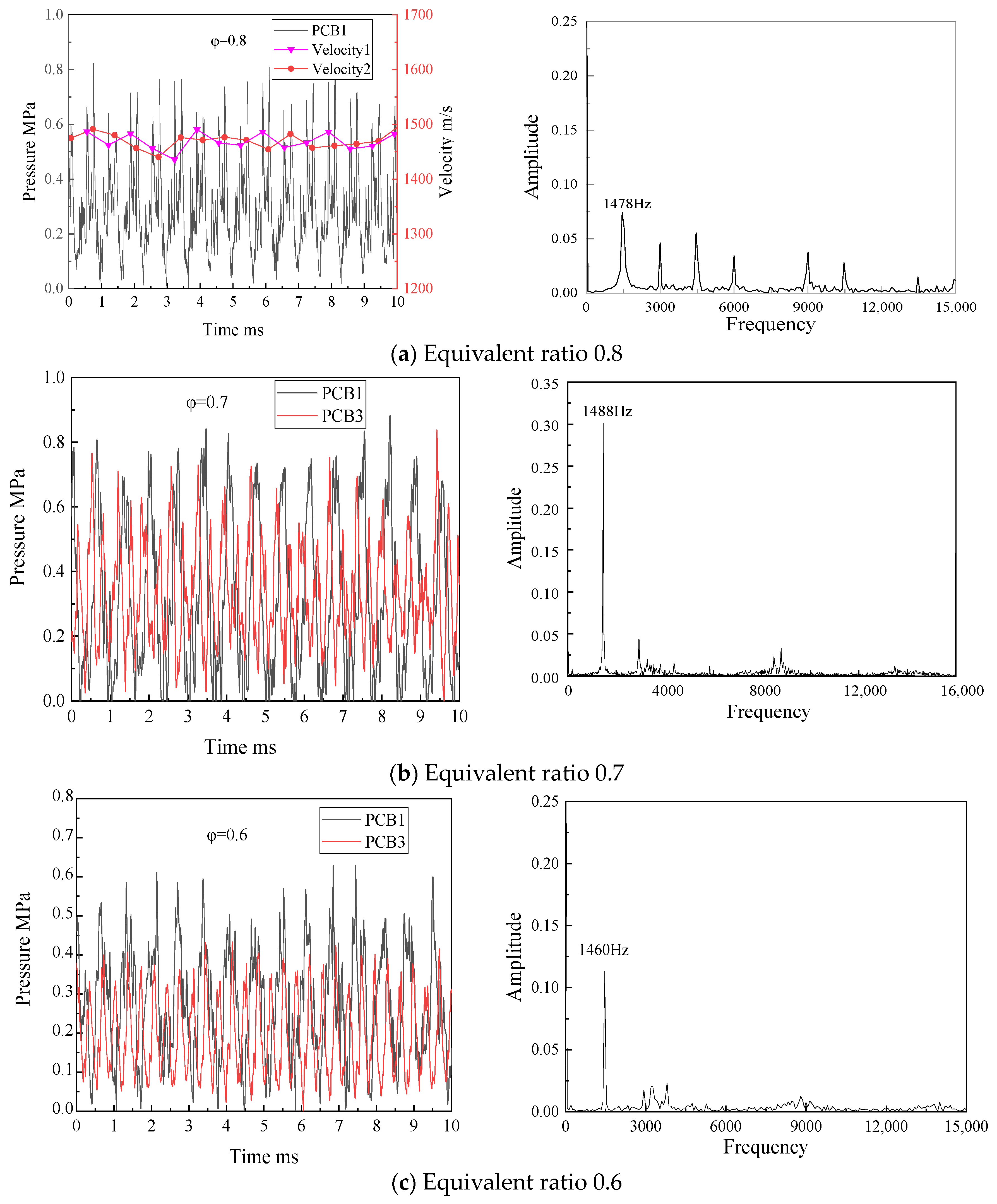
3.1. One-Direction Propagation Mode for the Rotating Detonation Wave

Figure 3 shows the pressure sequence and the Fast Fourier Transformation (FFT) results when the inlet mass flux is 400 kg/(m2s). As shown in Figure 3a, when the equivalence ratio is 0.8, the rotating detonation wave propagates in a fully developed single-wave mode. The average value of the detonation wave pressure peak is approximately 2 MPa, with a rotating detonation wave frequency of around 1814.4 Hz. The detonation wave propagation velocity can be calculated as 1710 m/s. As the equivalence ratio decreases, the detonation wave peak pressure decreases while the number of rotating detonation wavefronts increases. As shown in Figure 3b, the pressure sequences collected by PCB1 and PCB3 are similar, and the frequency of the rotating detonation wave is 3325 Hz, so it presents a two-wave, one-direction propagation mode for the rotating detonation wave when the equivalence ratio is 0.7. A three-wave, one-direction propagation mode of the rotating detonation wave appears when the equivalence ratios are 0.6 and 0.5, as depicted in Figure 3c,d, with the frequencies of the rotating detonation wave being 4810 Hz and 4701 Hz, respectively. The propagation velocity of the detonation wave is also provided in the pressure sequence figures. The detonation wave velocity is calculated by dividing the circumference of the outer cylinder of the combustion chamber by the time interval between two adjacent detonation wave peaks collected by PCB1. When the equivalent ratio decreases, the theoretical propagation velocity of the detonation wave decreases, and the decrease in the equivalent ratio is associated with a decrease in nozzle stiffness. This reduction in stiffness is influenced by factors such as decreased fuel injection pressure and diminished nozzle recovery time after the detonation wave passes. Consequently, the filling height of the subsequent cycle becomes insufficient, resulting in a decrease in detonation wave quality, peak pressure, and velocity. In the non-premixed chamber, a dual-wave system can emerge. This occurs when unburned reactants survive the leading detonation wave in the injector near field and are subsequently consumed within a trailing azimuthal reflected-shock combustion zone [39]. Furthermore, the trailing oblique shock wave reflects off the outer wall of the detonation chamber further downstream from the detonation wave. Since the detonation chamber lacks an inner tube structure, the unburned mixture begins to burn and gradually forms a new detonation front. Eventually, the system reaches a natural steady state of operation that balances mixture quality and wavefront quantity. Since the rotating detonation combustion cannot be initiated when the mixture equivalence ratio is lower than 0.5 in the tests, the equivalence ratio range is set between 0.5 and 0.8.

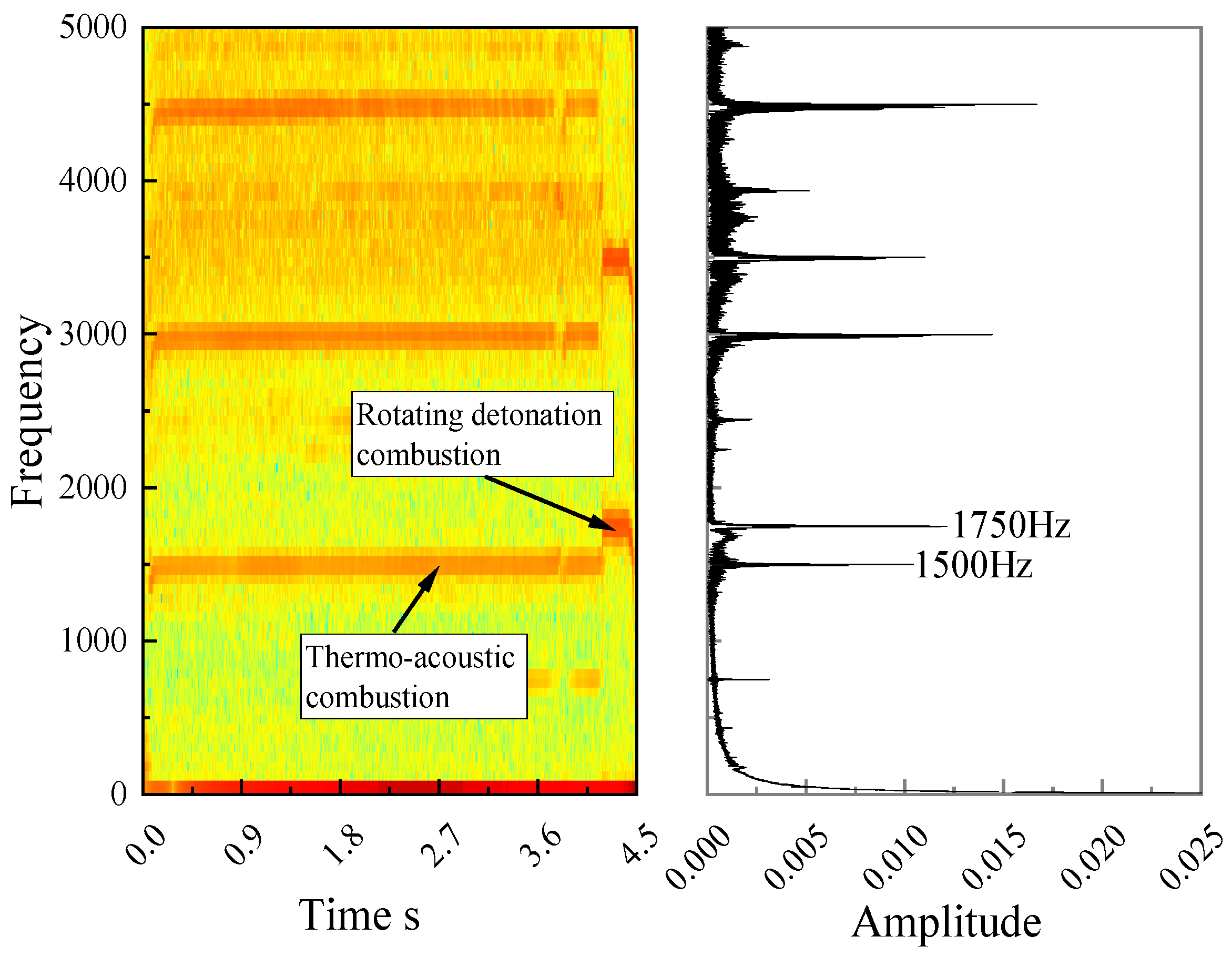
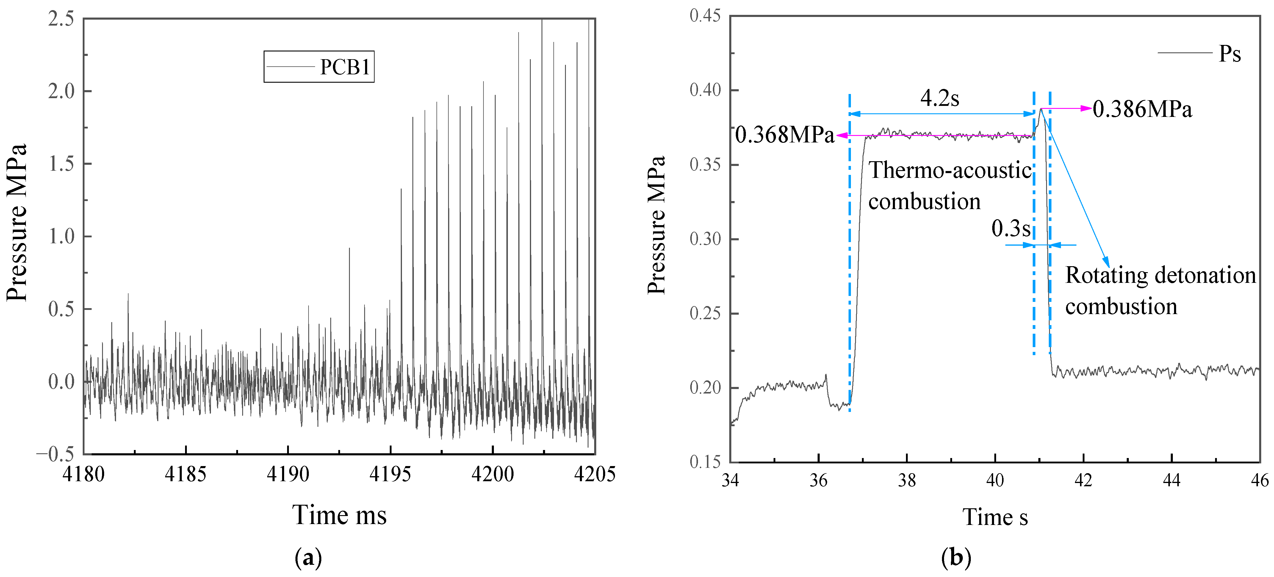
3.2. Transition of Tangential Thermo-Acoustic Combustion to Rotating Detonation Combustion

The rotating detonation wave becomes unstable when the inlet mass flux is 375 kg/(m2s), and the equivalent ratio is 0.8. The dynamic pressure sequence, along with the results of FFT and STFT, are displayed in Figure 4. In the dynamic pressure sequence diagram, the ignition time of the pre-detonation tube is at time zero. It can be observed that the basic frequency of the pressure wave is 1500 Hz during the first 4.2 s and 1750 Hz during the last 0.3 s. The frequency of 1500 Hz corresponds to thermo-acoustic combustion, while the frequency of 1750 Hz corresponds to rotating detonation wave combustion. A partially enlarged detail of tangential thermo-acoustic combustion is shown in Figure 5a. The total temperature of the incoming flow is 1250 K, and the mixture equivalence ratio is 0.8. Consequently, the total temperature of the burned gas can be estimated to be around 2610 K using the program developed by the research group. Since the Mach number of the gas flow is less than 0.3 in the chamber, the static temperature is close to the total temperature. Thus, the sound velocity of the burned gas can be estimated to be 959 m/s using the total temperature. With an outer diameter of 300 mm for the chamber, the tangential oscillation frequency in the combustion chamber is calculated to be 1425 Hz, based on the method introduced in the literature [43]. This presents a deviation of 5% when compared with the measured 1500 Hz in the test. Considering that there are errors in the test and calculation processes, the combustion mode during the first 4.2 s can be confirmed as tangential thermo-acoustic coupling combustion. The pressure sequence and propagation velocity of rotating detonation combustion are shown in Figure 5b. The average value of the detonation wave pressure peak is approximately 2 MPa, and the average velocity of detonation wave propagation is about 1610 m/s based on the frequency of 1750 Hz. Because the total temperature of the incoming air is as high as 1250 K, the kerosene quickly turns into steam in the high-temperature airflow. So, it assumes that the mixture in front of the detonation is gaseous, and the air and gaseous kerosene are mixed well. The C-J values of the pressure and the propagation velocity of the rotating detonation wave are computed by the NASA CEA [44]. The C-J theoretical velocity and pressure of the detonation wave are estimated to be 1694 m/s and 2.1 MPa, respectively. The measured velocity of rotating detonation wave propagation is slightly lower than the C-J theoretical value, as is the peak pressure. Since the deviation range is within 5%, it is confirmed that the rotating detonation wave is in the C-J detonation state during the last 0.3 s. Figure 6 displays the dynamic pressure and static pressure sequences of the combustion chamber when the combustion mode transitions from thermo-acoustic combustion to rotating detonation combustion. It can be observed that the static pressure in the combustion chamber increases from 0.368 MPa to 0.386 MPa. This results in a static pressure increase of about 5% for the rotating detonation combustion mode in the chamber. The pressure in the vitiator is higher than 2 MPa; meanwhile, the average pressure in the rotating detonation chamber is lower than 0.4 MPa, so the mass flow rate of the chamber is constant. According to the one-dimensional flow equation of m = 0.04 P * T * q ( λ ) , the total pressure increases by 5%, so the total temperature should increase by about 10%. It can be concluded that the efficiency of rotating detonation combustion in the chamber is higher than that of thermo-acoustic combustion. The specific impulse of RDE is improved by more than 10%, demonstrating the superior performance of detonation combustion.

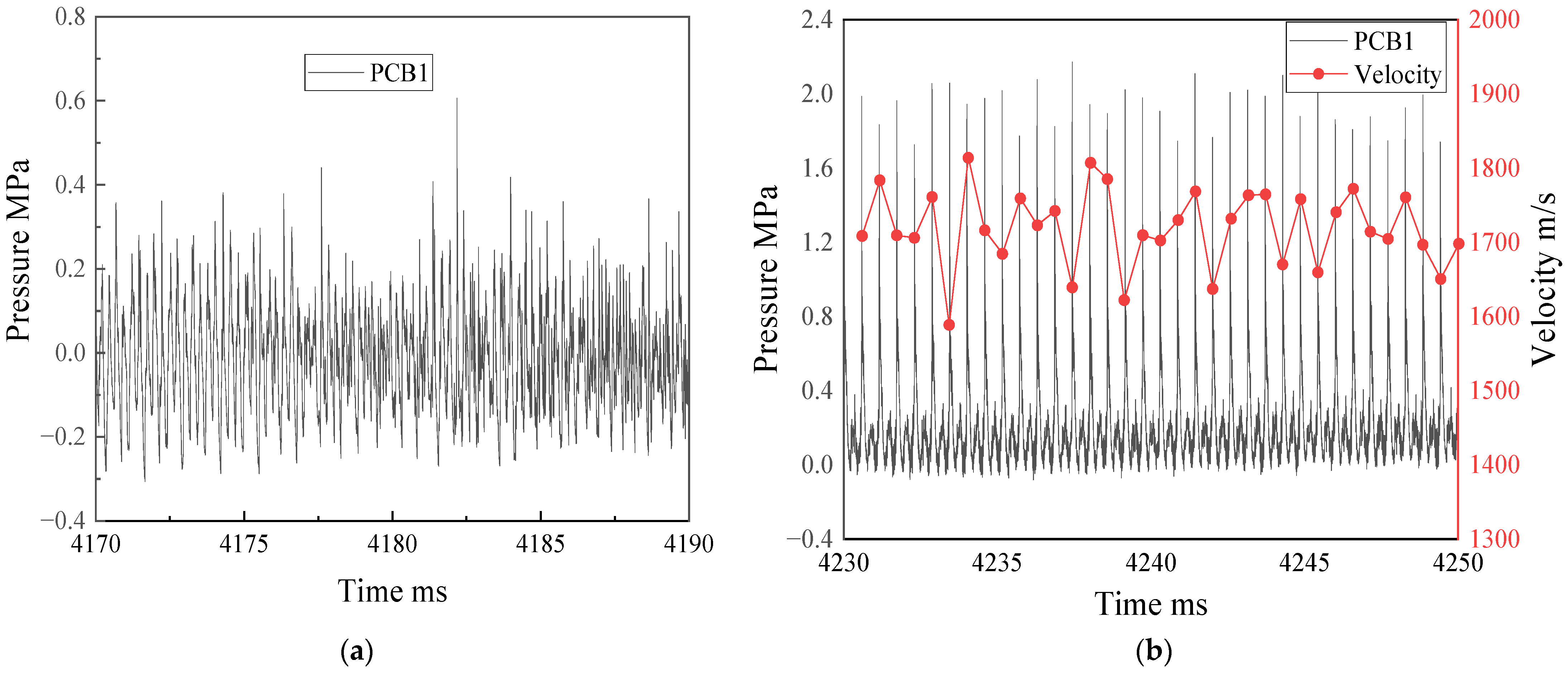
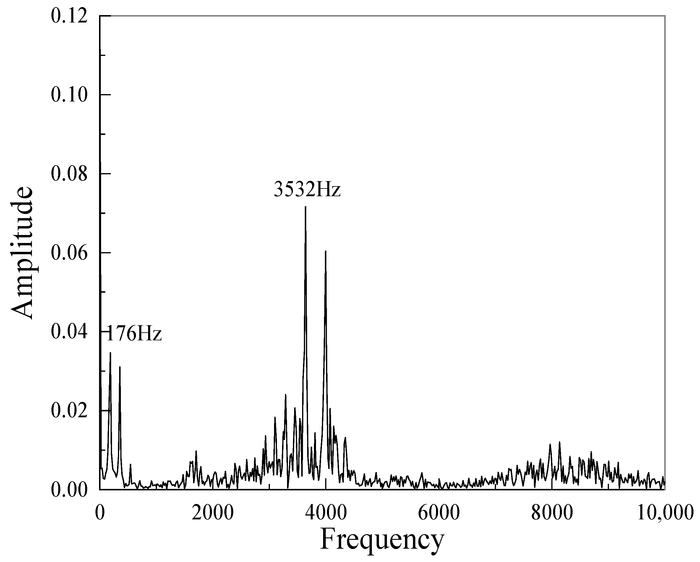
3.3. Axial Pressure Pulsation Superimposed on Rotating Detonation Combustion

When the inlet mass flux is 350 kg/(m2s), the total temperature of the incoming flow is 1250 K, and the equivalent ratio is 0.8, the peak pressure of the rotating detonation wave is lower than 0.8 MPa, and there is a low-frequency pulsation superimposed on rotating detonation combustion, as shown in Figure 7. The low-frequency pulsation with a period of about 5.7 ms is likely caused by pressure wave oscillation between the heater acoustic throat and the nozzle acoustic throat. As shown in Figure 1, the distance from the heater acoustic throat to the PCB1 sensor is 1510 mm, the distance from the PCB1 sensor to the combustion nozzle throat is 490 mm, and the total temperature of incoming flow is 1250 K. Because the Mach number of the incoming flow in the inlet section is less than 0.3, the static temperature is close to the total temperature, and the sound velocity is estimated to be about 709 m/s based on the total temperature. Therefore, it takes about 4.26 ms for the pressure wave to propagate from PCB1 upstream to the heater throat and back to PCB1. When the total temperature of the burned gas in the combustion chamber is about 2610 K, and the velocity of sound in the chamber is about 959 m/s, then it takes about 1.02 ms for the pressure wave propagating from PCB1 to the nozzle throat and back to PCB1. It shows the pressure sequence measured by the dynamic pressure sensor and the filtered results in Figure 7a, and a period of the filtered pressure sequence is enlarged in Figure 7b. In the figure, the compression wave propagates upstream through the dynamic pressure sensor PCB1 and then reaches the heater acoustic throat at moment 1, and the reflected expansion wave propagates downstream; the expansion wave reaches the dynamic pressure sensor PCB1 at moment 2 and then propagates to the nozzle acoustic throat reflecting a compression wave; the compression wave reaches the dynamic pressure sensor PCB1 again at moment 1′. It takes about 4.4 s from moment 1 to 2, longer than the estimated time of 4.26 ms, probably because the intake ducting absorbs the heat of the incoming flow, the total temperature drops, and the velocity of sound is also reduced. It takes about 1.3 ms from moment 2 to 1′, also longer than the estimated value, probably because that (1) the actual combustion efficiency is less than 1, and the total temperature of burned gas in the combustion chamber is less than the total theoretical temperature of 2610 K, and (2) it takes some time for the heat release of combustion progress, so the gas would reach the maximum temperature at the end of the combustion chamber. Therefore, the average velocity of sound for the burned gas in the combustion chamber is also less than 959 m/s. In general, the period of axial pulsation propagation of the pressure wave is longer than the estimated value.
The dynamic pressure FFT results in Figure 8 show two main frequencies: one of 176 Hz corresponding to the axial pressure pulsation, and the other of 3532 Hz corresponding to the two-wave rotating detonation in one-direction propagation mode. As shown in Figure 7b, the peak pressure of the rotating detonation waves changes with the axial pulsation pressure, i.e., the maximum value for detonation wave pressure is about 1 MPa, and the minimum value is about 0.2 MPa, which is due to the different initial pressure of the mixture in front of rotating detonation wave.

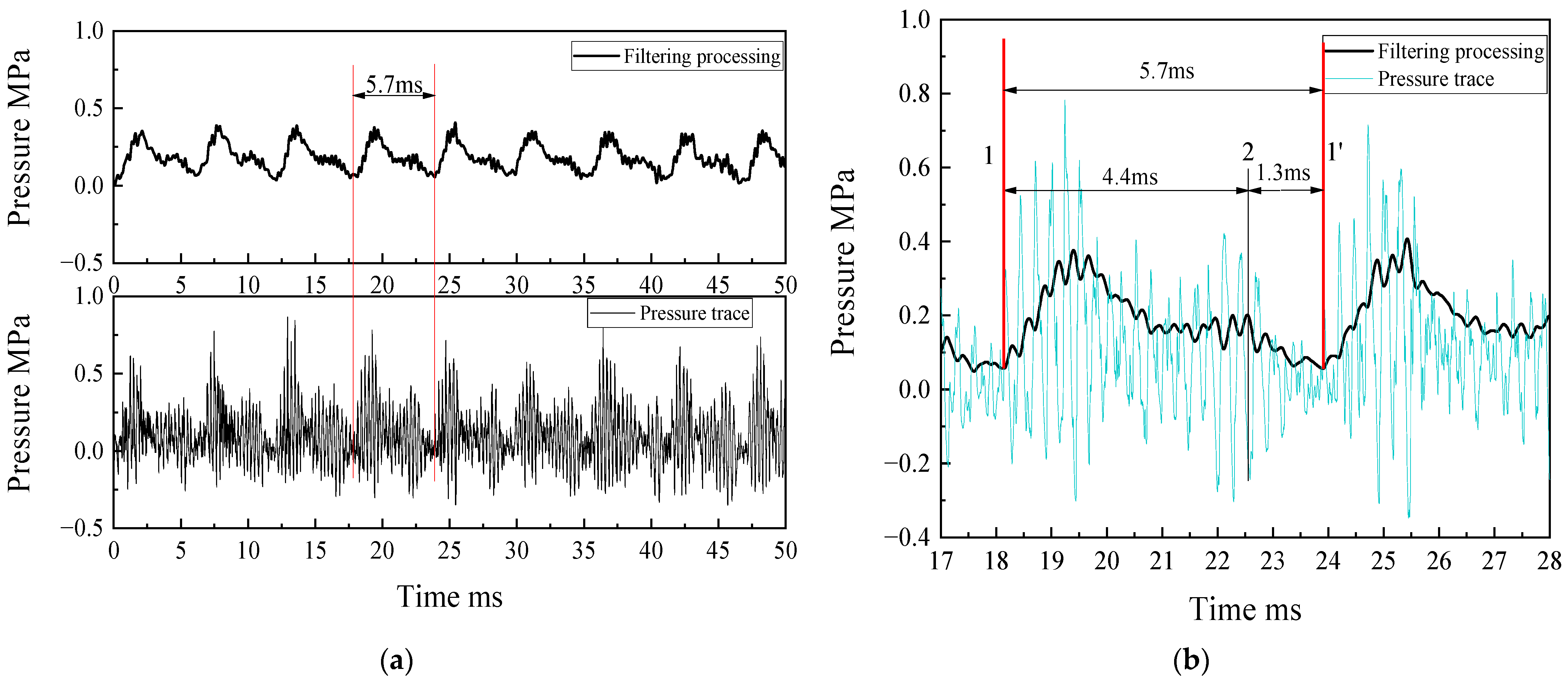
3.4. Rotating Detonation Combustion Mode of Two-Wave Collision

When the mass flux is reduced to 300 kg/(m2s), the rotating detonation wave in the detonation chamber tends to be a two-wave collision mode. When the equivalent ratio is 0.8, it can be seen that the time interval of the pressure peak appears alternately in the time sequence of PCB1, which is a typical two-wave collision propagation mode of the rotating detonation waves. When the equivalent ratios are 0.7 and 0.6, it can be seen from Figure 9b,c. The number of pressure peaks collected by PCB3 is about twice that of PCB1, so the collision point of the rotating detonation waves is near the PCB1 sensor, and the peak pressure measured by PCB1 at the equivalent ratio 0.7 is higher than that of equivalent ratio 0.8. In Figure 9, when the equivalent ratio changes, the propagation frequency of the collision rotating detonation waves changes slightly, and the propagation speed is much lower than the C-J theoretical value due to the process of developing from transmit shock to the rotating detonation wave each period after collision.

4. Conclusions

In conclusion, this study has experimentally investigated the propagation mode of rotating detonation waves for liquid hydrocarbon fuel and high-enthalpy air mixtures in a hollow cylinder chamber. The main findings of this study are:
(1)
With the use of liquid hydrocarbon fuel, a fully developed rotating detonation wave can be achieved under conditions of high incoming air total temperature of 1250 K.
(2)
The stability of the rotating detonation wave is more favorable at higher inlet mass flux. In the tested engine structure, the rotating detonation pressure peak and velocity in single-wave mode are close to those of C-J theoretical values at an equivalent ratio of 0.8 when the mass flux is 400 kg/(m2s).
(3)
When the mixture equivalent ratio decreases from 0.8 to 0.5 at the same inlet mass flux, the quantity of rotating detonation waves in the combustion chamber increases while the pressure peak of the detonation wave and its propagation velocity decrease.
(4)
A transformation from thermo-acoustic combustion to rotating detonation operation is observed. This effect shows an increase in mean chamber pressure and Isp of the engine—both of which indicate a potential for higher performance of an engine from detonative operation.
(5)
At an inlet mass flux of 350 kg/(m2s), axial pressure pulsation is observed superimposed on rotating detonation combustion in the combustion chamber, indicating a positive correlation between the pressure peak of the detonation wave and the change in static pressure in the combustion chamber.
(6)
In collision mode, the rotating detonation wave undergoes a transition process from transmitted shock to detonation wave during each period, resulting in the propagation velocity significantly lower than the C-J theoretical velocity.

Author Contributions

Conceptualization, Y.Z.; methodology, Y.H.; validation, B.J. and F.M.; formal analysis, H.P.; resources, Y.Z.; data curation, H.P. and H.M.; writing, original draft preparation, B.J., H.M., F.M. and H.P.; writing, review and editing, Y.Z., Y.H., B.J. and H.M.; project administration, H.M. All authors have read and agreed to the published version of the manuscript.

Funding

This research received no external funding.

Data Availability Statement

Not applicable.

Conflicts of Interest

The authors declare no conflict of interest.

References

  1. Kailasanath, K. Recent developments in the research on pulse detonation engines. AIAA J. 2003, 41, 145–159. [Google Scholar] [CrossRef]
  2. Roy, G.D.; Frolov, S.M.; Borisov, A.A.; Netzer, D.W. Pulse detonation propulsion: Challenges, current status, and future perspective. Prog. Energy Combust. Sci. 2004, 30, 545–672. [Google Scholar] [CrossRef]
  3. Wolański, P. Detonative propulsion. Proc. Combust. Inst. 2013, 34, 125–158. [Google Scholar] [CrossRef]
  4. Lu, F.K.; Eric, M.B. Rotating detonation wave propulsion: Experimental challenges, modeling, and engine concepts. J. Propuls. Power 2014, 30, 1125–1142. [Google Scholar] [CrossRef] [Green Version]
  5. Pratt, D.T.; Humphrey, J.W.; Glenn, D.E. Morphology of standing oblique detonation waves. J. Propuls. Power 1991, 7, 837–845. [Google Scholar] [CrossRef]
  6. Powers, J.M. Oblique Detonations-Theory and Propulsion Applications. Combustion in High-Speed Flows; Kluwer Academic Publishers: Dordrecht, The Netherlands, 1994; pp. 345–371. [Google Scholar] [CrossRef] [Green Version]
  7. Teng, H.H.; Ng, H.D.; Li, K.; Luo, C.; Jiang, Z. Evolution of cellular structures on oblique detonation surfaces. Combust. Flame 2015, 162, 470–477. [Google Scholar] [CrossRef] [Green Version]
  8. Naples, A.; Hoke, J.; Battelle, R.T.; Wagner, M.; Schauer, F.R. RDE implementation into an open-loop T63 gas turbine engine. In Proceedings of the 55th AIAA Aerospace Sciences Meeting, Grapevine, TX, USA, 9–13 January 2017. [Google Scholar] [CrossRef]
  9. Assad, M.; Penyzkov, O.; Chernukho, I. Symbiosis of deflagration and detonation in one jet system–A hybrid detonation engine. Appl. Energy 2022, 322, 119474. [Google Scholar] [CrossRef]
  10. Nicholls, J.A.; Cullen, R.E.; Ragland, K.W. Feasibility studies of a rotating detonation wave rocket motor. J. Spacecr. Rocket. 1966, 3, 893–898. [Google Scholar] [CrossRef]
  11. Fotia, M.; Kaemming, T.A.; Hoke, J.; Schauer, F. Study of the experimental performance of a rotating detonation engine with nozzled exhaust flow. In Proceedings of the 53rd AIAA Aerospace Sciences Meeting, Kissimmee, FL, USA, 5–9 January 2015. [Google Scholar] [CrossRef]
  12. Tang, X.M.; Wang, J.P.; Shao, Y.T. Three-dimensional numerical investigations of the rotating detonation engine with a hollow combustor. Combust. Flame 2015, 162, 997–1008. [Google Scholar] [CrossRef]
  13. Lin, W.; Zhou, J.; Liu, S.; Lin, Z. An experimental study on CH4/O2 continuously rotating detonation wave in a hollow combustion chamber. Exp. Therm Fluid Sci. 2015, 62, 122–130. [Google Scholar] [CrossRef]
  14. Stoddard, W.; St. George, A.C.; Driscoll, R.B.; Anand, V.; Gutmark, E.J. Experimental validation of expanded centerbodiless RDE design. In Proceedings of the 54th AIAA Aerospace Sciences Meeting, San Diego, CA, USA, 4–8 January 2016. [Google Scholar] [CrossRef]
  15. Wiggins, R.; Gaetano, A.; Pritschau, T.; Betancourt, J.; Shaw, V.; Anand, V.; Gutmark, E. Rotating Detonations in Hollow and Flow-Through Combustors. AIAA J. 2023, 61, 86–96. [Google Scholar] [CrossRef]
  16. Rodriguez, V.; Jourdain, C.; Vidal, P.; Zitoun, R. An experimental evidence of steadily-rotating overdriven detonation. Combust. Flame 2019, 202, 132–142. [Google Scholar] [CrossRef]
  17. Yokoo, R.; Goto, K.; Kasahara, J.; Athmanathan, V.; Braun, J.; Paniagua, G.; Meyer, T.R.; Kawasaki, A.; Matsuoka, K.; Matsuo, A.; et al. Experimental study of internal flow structures in cylindrical rotating detonation engines. Proc. Combust. Inst. 2021, 38, 3759–3768. [Google Scholar] [CrossRef]
  18. Braun, E.M.; Lu, F.K.; Wilson, D.R.; Camberos, J.A. Airbreathing rotating detonation wave engine cycle analysis. Aerosp. Sci. Technol. 2013, 27, 201–208. [Google Scholar] [CrossRef] [Green Version]
  19. Frolov, S.M.; Zvegintsev, V.I.; Ivanov, V.S.; Aksenov, V.S.; Shamshin, I.O.; Vnuchkov, D.A.; Nalivaichenko, D.G.; Berlin, A.A.; Fomin, V.M.; Shiplyuk, A.N.; et al. Hydrogen-fueled detonation ramjet model: Wind tunnel tests at approach air stream Mach number 5.7 and stagnation temperature 1500 K. Int. J. Hydrogen Energy 2018, 43, 7515–7524. [Google Scholar] [CrossRef]
  20. Liu, S.; Liu, W.; Wang, Y.; Lin, Z. Free jet test of continuous rotating detonation ramjet engine. In Proceedings of the 21st AIAA International Space Planes and Hypersonics Technologies Conference, Xiamen, China, 6–9 March 2017. [Google Scholar]
  21. Bykovskii, F.A.; Zhdan, S.A.; Vedernikov, E.F. Vedernikov. Continuous spin detonations. J. Propuls. Power 2006, 22, 1204–1216. [Google Scholar] [CrossRef]
  22. Deng, L.; Ma, H.; Xu, C.; Zhou, C.; Liu, X. Investigation on the propagation process of rotating detonation wave. Acta Astronaut. 2017, 139, 278–287. [Google Scholar] [CrossRef]
  23. Deng, L.; Ma, H.; Xu, C.; Liu, X.; Zhou, C. The feasibility of mode control in rotating detonation engine. Appl. Therm. Eng. 2018, 129, 1538–1550. [Google Scholar] [CrossRef]
  24. Zhou, S.; Ma, H.; Zhou, C.; Hu, N. Experimental research on the propagation process of rotating detonation wave with a gaseous hydrocarbon mixture fuel. Acta Astronaut. 2021, 179, 1–10. [Google Scholar] [CrossRef]
  25. Teng, H.; Zhou, L.; Yang, P.; Jiang, Z. Numerical investigation of wavelet features in rotating detonations with a two-step induction-reaction model. Int. J. Hydrogen Energy 2020, 45, 4991–5001. [Google Scholar] [CrossRef]
  26. Yao, K.; Yang, P.; Teng, H.; Chen, Z.; Wang, C. Effects of injection parameters on propagation patterns of hydrogen-fueled rotating detonation waves. Int. J. Hydrogen Energy 2022, 47, 38811–38822. [Google Scholar] [CrossRef]
  27. Zhao, M.; Wang, K.; Zhu, Y.; Wang, Z.; Yan, Y.; Wang, Y.; Fan, W. Effects of the exit convergent ratio on the propagation behavior of rotating detonations utilizing liquid kerosene. Acta Astronaut. 2022, 193, 35–43. [Google Scholar] [CrossRef]
  28. Ding, C.; Wu, Y.; Xu, G.; Xia, Y.; Li, Q.; Weng, C. Effects of the oxygen mass fraction on the wave propagation modes in a kerosene-fueled rotating detonation combustor. Acta Astronaut. 2022, 195, 204–214. [Google Scholar] [CrossRef]
  29. Kindracki, J.; Wacko, K.; Woźniak, P.; Siatkowski, S.; Mężyk, Ł. Influence of Gaseous Hydrogen Addition on Initiation of Rotating Detonation in Liquid Fuel–Air Mixtures. Energies 2020, 13, 5101. [Google Scholar] [CrossRef]
  30. Jia, B.; Zhang, Y.; Pan, H.; Hong, Y. Experimental study on initiation process of liquid hydrocarbon rotating detonation engine. J. Propuls. Technol. 2021, 42, 906–914. [Google Scholar] [CrossRef]
  31. Ge, G.; Ma, Y.; Xia, Z.; Ma, H.; Deng, L.; Zhou, C. Experimental Research of Two-phase Rotating Detonation Combustor Operating with High Total Temperature Air. J. Appl. Fluid Mech. 2022, 15, 1437–1449. [Google Scholar] [CrossRef]
  32. Bykovskii, F.A.; Zhdan, S.A.; Vedernikov, E.F. Continuous spin detonation of a heterogeneous kerosene–air mixture with addition of hydrogen. Combust. Explos. Shock 2016, 52, 371–373. [Google Scholar] [CrossRef]
  33. Bykovskii, F.A.; Zhdan, S.A.; Vedernikov, E.F. Continuous detonation of the liquid kerosene—Air mixture with addition of hydrogen or syngas. Combust. Explos. Shock 2019, 55, 589–598. [Google Scholar] [CrossRef]
  34. Xu, S.; Song, F.; Zhou, J.; Yang, X.; Cheng, P. Experimental Study on Propagation Characteristics of Kerosene/Air RDE with Different Diameters. Energies 2022, 15, 4442. [Google Scholar] [CrossRef]
  35. Le Naour, B.; Falempin, F.H.; Coulon, K. MBDA R&T effort regarding continuous detonation wave engine for propulsion-status in 2016. In Proceedings of the 21st AIAA International Space Planes and Hypersonics Technologies Conference, Xiamen, China, 6–9 March 2017. [Google Scholar] [CrossRef]
  36. Anderson, W.S.; Heister, S.D. Response of a liquid jet in a multiple-detonation driven crossflow. J. Propuls. Power 2019, 35, 303–312. [Google Scholar] [CrossRef]
  37. Hoeper, M.W.; Webb, A.M.; Athmanathan, V.; Wang, R.B.; Perkins, H.D.; Roy, S.; Meyer, T.R.; Fugger, C.A. Liquid fuel refill dynamics in a rotating detonation combustor using megahertz planar laser-induced fluorescence. Proc. Combust. Inst. 2023, 39, 3051–3061. [Google Scholar] [CrossRef]
  38. Black, C.H.; Winter, T.R.; Jackson, D.R.; Frederick, M.; Gejji, R.; Slabaugh, C.D.; Perkins, H.D.; Fugger, C.A. Liquid Jet Response to Detonation Waves in a Linear Detonation Combustor. In Proceedings of the AIAA SCITECH 2023 Forum, National Harbor, MD, USA & Online, 23–27 January 2023. [Google Scholar] [CrossRef]
  39. Raman, V.; Prakash, S.; Gamba, M. Nonidealities in Rotating Detonation Engines. Annu. Rev. Fluid Mech. 2023, 55, 639–674. [Google Scholar] [CrossRef]
  40. Burr, J.R.; Paulson, E. Thermodynamic performance results for rotating detonation rocket engine with distributed heat addition using Cantera. In Proceedings of the AIAA Propulsion and Energy 2021 Forum, Online, 9–11 August 2021. [Google Scholar] [CrossRef]
  41. Ayers, Z.M.; Athmanathan, V.; Meyer, T.R.; Paxson, D.E. Variably Premixed Rotating Detonation Engine for Evaluation of Detonation Cycle Dynamics. J. Propuls. Power 2023, 39, 351–364. [Google Scholar] [CrossRef]
  42. Athmanathan, V.; Braun, J.; Ayers, Z.M.; Fugger, C.A.; Webb, A.M.; Slipchenko, M.N.; Paniagua, G.; Roy, S.; Meyer, T.R. On the effects of reactant stratification and wall curvature in non-premixed rotating detonation combustors. Combust. Flame 2022, 240, 112013. [Google Scholar] [CrossRef]
  43. Jesuthasan, A. Near-Limit Propagation of Detonations in Annular Channels. Master’s Thesis, McGill University, Montreal, QC, Canada, 2011. [Google Scholar]
  44. NASA Glenn Research Center. CEAgui-Win, Chemical Equilibrium with Applications GUI for Windows, Software Package, Version 28; NASA Glenn Research Center: Cleveland, OH, USA, 2005.
Figure 1. Geometry structure of RDE experimental set (not to scale).
Aerospace 10 00682 g001
Figure 2. Three-dimensional model of the RDE.
Aerospace 10 00682 g002
Figure 3. Pressure sequence and FFT results of rotating detonation wave in combustion chamber as the inlet mass flux is 400 kg/(m2s).
Aerospace 10 00682 g003aAerospace 10 00682 g003b
Figure 4. Analysis results of STFT and FFT for the measured pressure wave at an equivalence ratio of 0.8 as the inlet mass flux is 375 kg/(m2s).
Aerospace 10 00682 g004
Figure 5. Two combustion modes in the combustion chamber at an equivalence ratio of 0.8 as the inlet mass flux is 375 kg/(m2s): (a) thermo-acoustic combustion; (b) rotating detonation combustion.
Aerospace 10 00682 g005
Figure 6. Dynamic pressure and static pressure in combustion chamber at an equivalent ratio of 0.8 as the inlet mass flux is 375 kg/(m2s): (a) dynamic pressure in combustion chamber; (b) static pressure in combustion chamber.
Aerospace 10 00682 g006
Figure 7. Dynamic pressure and the filtered results in combustion chamber at an equivalent ratio of 0.8 as the inlet mass flux is 350 kg/(m2s): (a) dynamic pressure and the filtered results; (b) enlarged partial view.
Aerospace 10 00682 g007
Figure 8. Dynamic pressure in combustion chamber and the FFT results at an equivalence ratio of 0.8 as the inlet mass flux 350 kg/(m2s).
Aerospace 10 00682 g008
Figure 9. Dynamic pressure sequence and the FFT results as the inlet mass flux is 300 kg/(m2s).
Aerospace 10 00682 g009
Table 1. Test conditions for the rotating detonation combustion.
Condition No.Inlet Mass Flux kg/(m2s)Equivalent Ratio Range
14000.5~0.8
23750.5~0.8
33500.5~0.8
43000.5~0.8
Disclaimer/Publisher’s Note: The statements, opinions and data contained in all publications are solely those of the individual author(s) and contributor(s) and not of MDPI and/or the editor(s). MDPI and/or the editor(s) disclaim responsibility for any injury to people or property resulting from any ideas, methods, instructions or products referred to in the content.

