Article

A Review of Flapping Mechanisms for Avian-Inspired Flapping-Wing Air Vehicles

Department of Aerospace Engineering, Korea Advanced Institute of Science & Technology (KAIST), Daejeon 34141, Republic of Korea
*
Author to whom correspondence should be addressed.
Aerospace 2023, 10(6), 554; https://doi.org/10.3390/aerospace10060554
Submission received: 18 April 2023 / Revised: 28 May 2023 / Accepted: 30 May 2023 / Published: 12 June 2023
(This article belongs to the Section Aeronautics)

Abstract

:
This study focuses on the flapping mechanisms found in recently developed biometric flapping-wing air vehicles (FWAVs). FWAVs mimic the flight characteristics of flying animals, providing advantages such as maneuverability, inconspicuousness, and excellent flight efficiency in the low Reynolds number region. The flapping mechanism is a critical part of determining the aerodynamic performance of an FWAV since it is directly related to the wing motion. In this study, the flight characteristics of birds and bats are introduced, the incorporation of these flight characteristics into the development of FWAVs is elucidated, and the utilization of these flight characteristics in the development of FWAVs is explained. Next, the classification and analysis of flapping mechanisms are conducted based on wing motion and the strategy for improving aerodynamic performance. Lastly, the current research gap is elucidated, and potential future directions for further research are proposed. This review can serve as a guide during the early development stage of FWAVs.

1. Introduction

Flying animals such as birds and insects can fly effectively in complex and diverse environments. They have high flight efficiency, maneuverability, and environmental adaptability—characteristics that are difficult for human-made aircraft to replicate [1,2,3]. Various studies have been conducted to develop flapping-wing air vehicles (FWAVs) that mimic the excellent flight characteristics of these flying animals. Flying animals fly at a relatively lower Reynolds number than existing manned aerial vehicles, as shown in Figure 1 [4]. The Reynolds number is a dimensionless quantity that represents the ratio of inertial forces to viscous forces of a fluid. The reduced frequency is a dimensionless number representing the ratio of forward speed and flapping frequency. However, unmanned aerial vehicles (UAVs) operating in the low Reynolds number region can be improved by applying these advantageous animal flight characteristics.
Recently, with the increased use of UAVs, studies on biomimetic FWAVs have increased. Unlike rotorcraft, FWAVs do not use blades to obtain propulsion, providing relatively low noise and increased collision safety. In addition, they can be used for military purposes such as reconnaissance and surveillance because of their inconspicuous flying animal-like appearance. Festo’s Smartbird [5] was designed by imitating the flight of a seagull, and AeroVironment’s Nano hummingbird [6] was developed to have an appearance and flight characteristics similar to a hummingbird—flying forward and backward as well as hovering similar to a hummingbird. This model can perform real-world reconnaissance missions as it can obtain image information through a micro-camera.
Flying animals can be classified into insect or avian-scale [7]. Insects fly using a single-articulated wings connected to a thoracic hinge. Aerodynamic force is obtained through passive deformation of the wing shape [8]. Conversely, birds and bats have multi-articulated wings to increase aerodynamics through active wing deformation [9].
FWAVs can also be classified as avian or insect-inspired according to the flapping frequency and wing size. Insect-inspired FWAVs are driven at a high flapping frequency and can be used for indoor surveillance and reconnaissance. However, they are not suitable for performing outdoor missions due to their low stability against disturbance, relatively short flight time, and low payload capacity. However, avian-inspired FWAVs are driven at a relatively low flapping frequency, enable increased endurance by gliding, and are robust when performing outdoor missions because of their large payload capacity. In this paper, the standard for avian-inspired FWAV is an aircraft with a wingbeat frequency of less than 30 Hz, a wingspan of 200 mm or more, and mainly for forward flight rather than hovering.
Currently, most FWAVs are insect-inspired (from 1984 to 2014 [10]). Avian-inspired FWAVs are still in the development stage, and not many have been actively used in comparison to insect-inspired FWAVs. Recently, studies to improve avian-inspired FWAV performance have been actively conducted, and they are expected to overcome the stability and payload capacity limitations of insect-inspired FWAVs. Unlike insect-inspired FWAVs, which focus on light weight and high flapping frequency, avian-inspired FWAVs focus on withstanding relatively large loads due to their large wingspan. An FWAV flapping mechanism consists of an actuator and a transmission mechanism and converts the rotational or linear motion of the actuator to generate wing motions and, subsequently, aerodynamic force. Since the flapping mechanism generates aerodynamic force, it is a critical part in determining aerodynamic performance. In addition, the concept and development process of the flapping mechanism must differ based on the FWAV operating purpose and environment. Therefore, a review of the flapping mechanisms for avian-inspired FWAVs can be a valuable guide in the early FWAV development stages.
In this paper, the mechanisms for avian-inspired FWAVs are reviewed. The avian flight characteristics are first introduced, followed by an explanation of how current studies have successfully mimicked these flight characteristics. Next, various flapping mechanisms are classified and analyzed according to wing motion and the strategy for improving aerodynamic performance. Finally, the current research gap in FWAV studies is explained, and future directions for research in this field are proposed.

2. Avian Flight Characteristics

Flying animals are products of evolution with optimal flight performance according to their habitat, and their excellent aerodynamic flight characteristics provide great inspiration to engineers. By discussing which wing motions effectively generate aerodynamic force and which flight strategies they adopt, applicable strategies for FWAVs can be understood.
It is known that flying animals in nature can effectively fly in various and complex flight environments using their flapping wings [1,11,12]. Aerodynamic performance and efficiency can be improved by appropriately combining various wing motions. Various wing motions can be generated due to musculoskeletal interactions, as shown in Figure 2 [13,14,15].
During the flapping flight, most flying animals fold their wings during the upstroke by flexing the elbow and adducting the wrist, as shown in Figure 2a (wing folding) [16]. By folding the wing, drag and inertial cost are reduced because the wing’s moment of inertia can be reduced while reducing the span [17].
The twisting motion of the wing indicates that it rotates in the longitudinal direction of the wing, as shown in Figure 2b (twisting). Wings can be passively twisted by structural deformation and actively twisted through pronating and supinating the wrist [1,18]. By twisting the wing, wing tip stall can be prevented because the angle of attack is reduced at the wing tip. In addition, the flight speed can be controlled, or thrust can be increased by adjusting the twisting angle [19,20,21].
Flying animals can bend their wings perpendicular to the plane of the wing, as shown in Figure 2c (wrist flexing). In general, their wings are bent during the upstroke and extended during the downstroke—similar to folding and expanding. By flexing the wrist, they can achieve similar benefits to wing folding. As the wing bends during the upstroke, the moment of inertia of the wing is reduced, resulting in efficient flight. Wing folding and wrist flexing often occur simultaneously, resulting in increased lift and reduced drag compared to without wing bending and wrist flexing [22].
Muscles drive the flapping motion of birds and bats [23,24]. A bird’s wings are composed of overlapping feathers, whereas a bat’s consists of membranes. Birds usually bend their wings, and bats mainly fold their wings during the upstroke to increase aerodynamic efficiency [25]. Most birds can achieve cruising flight at all flight speeds, while hummingbirds and bats can perform low-speed maneuvering [26].
Flying animals adopt different flight strategies according to the flight environment and change their wing motions according to the flight speed [11,27,28]. In low-speed flight, birds with a high aspect ratio twist their wing until the wing tips are inverted with a large twisting angle. Hummingbirds fold less in hovering flight mode [29], and the folding angle varies depending on flight speed [30]. In addition, pigeons decrease their wing span, wing area, and aspect ratio by folding their elbow as their flight speed increases [31].
Flying animals increase their flight performance through various flight strategies and wing movement changes. Intermittent flapping is one such strategy which increases flight efficiency. For example, flapping-bounding is when wings are fixed to the body during flight, and flapping-gliding is when the wing is extended during flight.
Flapping-bounding mainly occurs in small-sized birds [32] and preserves energy in high-speed flight [33]. Rather than extending the wings to generate lift, they fold their wings to reduce drag and create lift from the body and tail wing. In flapping-gliding, the wing is extended to avoid continuous flapping at all flight speeds, thereby saving energy [32].
Bats also adopt a strategy to obtain aerodynamic benefits by reducing the area and span of their wings in high-speed flight [34,35]. However, compared to birds, their change in wing area is limited. For birds, it is easy to reduce the area of the wing because the feathers are separately overlapped; however, bat wings consist of membranes [36]. For example, pigeons can reduce their wing span and area to 37% and 62% of their maximum value [37], while dog-faced bats can only reduce their wing span and area to 83% and 70% of their maximum value [36]. Instead, bats can adjust the camber of their wings according to flight speed, so they can more effectively generate high lift at high angles of attack [9].

3. Flapping Mechanism

The following section provides an analysis of how flapping mechanisms emulate the wing motions of flying animals, and the aerodynamic advantages derived from the flapping motions are discussed.

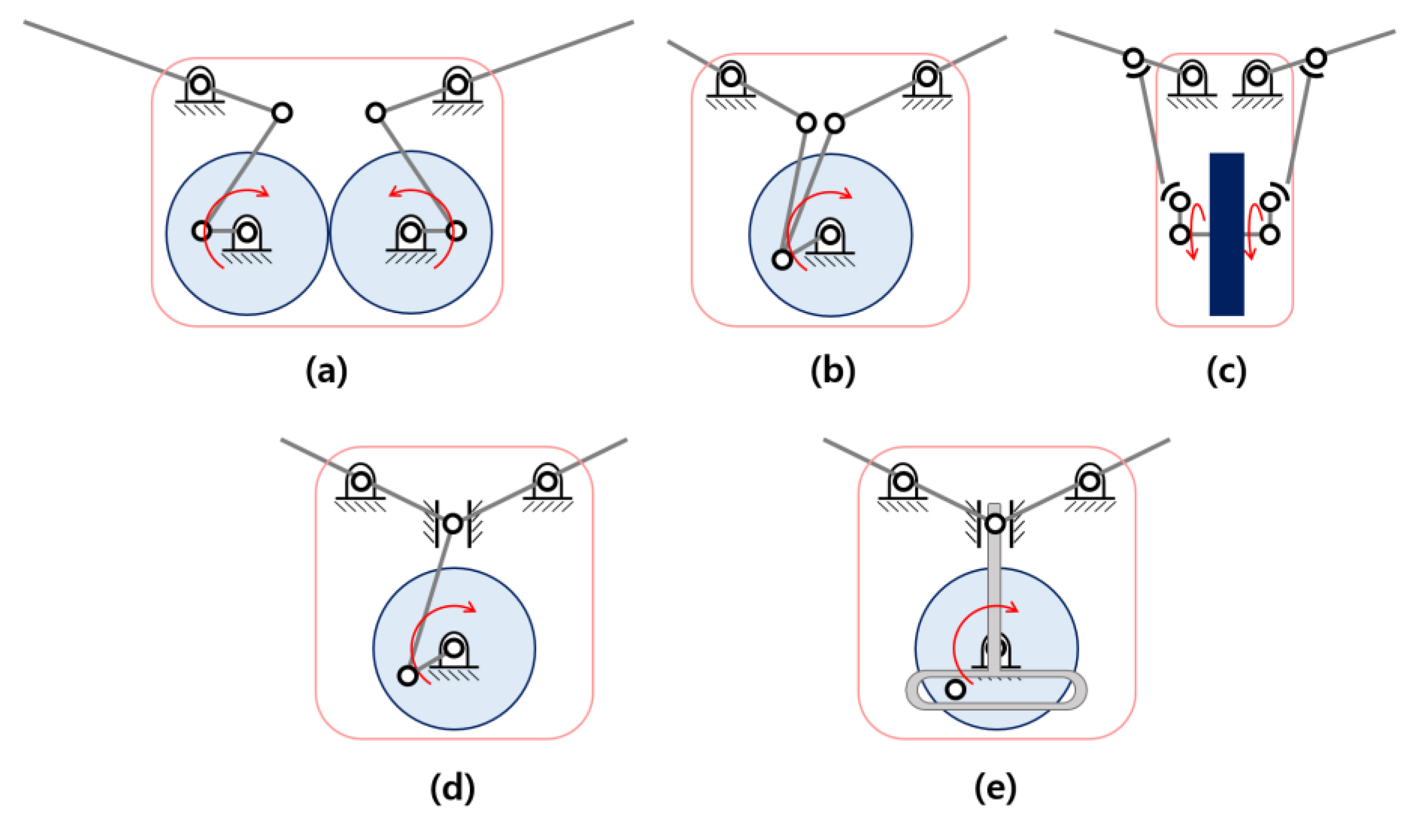
3.1. Classification of the Flapping Mechanism According to Wing Motions

The wing motions of currently developed FWAVs are different from those of actual flying animals. This is because, unlike animal wings that are composed of muscles and bones, FWAVs are composed of actuators and transmission mechanisms, making it difficult to realize all the complex wing motions found in avians. Due to these limitations, FWAVs have used mechanisms that realize only some wing motions rather than imitating all the wing motions of flying animals.
Depending on the wing motion, flapping mechanisms can be classified into those that can generate motion in one axis or those that can generate multi-axis, as shown in Figure 3.

3.1.1. One-Axis Flapping Mechanism

Mechanisms that can only move in one axis have the advantage of reducing weight and complexity due to utilizing a simple mechanism. One-axis flapping mechanisms can be classified into rigid mechanisms and compliant mechanisms. A rigid mechanism refers to a mechanism in which all parts of the mechanism are rigid parts, and a compliant mechanism refers to a mechanism including at least one flexible part, such as some compliant joints.
Rigid mechanisms
A four-bar linkage mechanism is a typical mechanism capable of one-axis motion. These include a four-bar planar linkage mechanism based on the crank-rocker mechanism using four revolute joints and a four-bar spatial linkage mechanism using two spherical joints and two revolute joints, as shown in Figure 4a–c.
There are also double-crank double-rocker mechanisms (Figure 4a) and single-crank double-rocker mechanisms (Figure 4b) based on the four-bar planar linkage mechanism. The single-crank double-rocker mechanism has a relatively small body width because it can drive two couplers and rockers by one crank; however, a phase difference between both wings occurs, causing asymmetric wing motion. Wang et al. [85] addressed this issue by defining the phase difference of both wings as the optimization problem. Meanwhile, the double-crank double-rocker mechanism can drive each rocker with each crank, and the two cranks are driven simultaneously with a pair of gears without phase difference between both wings. For this reason, the double-crank double-rocker mechanism has been used in many FWAVs.
A four-bar spatial linkage mechanism operates in 3D space, as shown in Figure 4c, and the direction of the flapping motion and the rotation direction of the crank are perpendicular. This mechanism can greatly reduce the width of the body, consequently reducing the drag generated by the body. Since the four-bar linkage mechanism is easily combined with a DC motor, can be driven with relatively low voltage, and has high energy efficiency and maximum torque, it has been widely used, from avian-inspired FWAVs with large wings to insect-inspired FWAVs with small wings. However, the flapping angle amplitude that can be implemented with a four-bar linkage mechanism is not large.
Additionally, there are cases in which flapping motion has been generated using a slide-crank or scotch-yoke mechanism, as depicted in Figure 4d,e, respectively. A slide-crank mechanism converts the rotational motion of the motor into linear motion. Using linear motion, it can then overcome the limited flapping angle amplitude of the four-bar linkage mechanism or implement various wing motions. Similar to the slide-crank mechanism, a scotch-yoke mechanism uses rotational motion of the actuator to generate linear motion as the slider and the piston connected to the slider reciprocates. Unlike the slide-crank mechanism, it generates a simple harmonic motion.
Compliant mechanisms
Unlike the rigid mechanism composed of rigid links and joints, a compliant mechanism is composed of flexible materials that can be deformed. Compliant mechanisms have mainly been used for insect-inspired FWAV because they have less friction, can be manufactured in a small size, and are light compared to flapping mechanisms composed of rigid bodies. Compliant mechanisms are classified into flexible frames and flexible joints.
Madangopal et al. [38] proposed a design concept of the flapping mechanism that combines springs with joints of a four-bar linkage mechanism. The kinetic energy of the wing is stored in the form of elastic energy and then released again as kinetic energy. Figure 5a illustrates a mechanism that produces the same effect by combining a linear spring with the slide of the slide-crank mechanism.
To solve the mechanical vibration and abrasion problem of the rigid mechanism, the compliant frame flapping motion can be driven by flexible frame instead of rigid linkages. The mechanism effectively reduced the mass of the operating part. The compliant mechanism can also reduce the difference between largest and smallest load, thus improving the reliability of the electronic components. Figure 5b shows one example of the flexible frame flapping mechanism [40]. The frame of this mechanism was manufactured as single piece by using injection molding. However, since it is inferior to the rigid mechanism in terms of transmission efficiency, it is less suitable for avian-inspired FWAVs with relatively large and heavy wings compared to insect-inspired FWAVs. For these reasons, compliant mechanisms have been used as an additional mechanism to generate other wing motions rather than being used in the driving mechanism to generate flapping motion.
The classification and reference of one-axis flapping mechanisms are listed in Table 1.

3.1.2. Multi-Axis Flapping Mechanism

The flapping mechanisms introduced above can only generate flapping motion and require an additional mechanism or actuator to increase stability, maneuverability, and aerodynamic performance. To improve aerodynamic performance, mechanisms that can generate multi-axis have been studied, and several benefits have been obtained by imitating the wing motion of flying animals.
Wing folding and flapping mechanisms
Folding motion is mainly seen in FWAVs that mimic bats. Many foldable FWAVs have used an articulated mechanism that utilizes wing linkage to implement folding motion. The folding mechanism is similar to the skeleton structure of flying animals, and the wings can be folded through the mechanism, as shown in Figure 6. The mechanism has a prismatic joint with a linear motion driven by a slide-crank mechanism or a servo motor.
Hoff et al. [58] developed a flapping mechanism similar to the skeleton of a bat’s wing using rigid links and joints. The flapping mechanism is a one-degree-of-freedom mechanism that can simultaneously generate flapping motion and folding motion. Chen et al. [59] developed a folding mechanism composed of links and joints, which can be folded similarly to the structure of a bird’s wing; servo motors control whether each wing is folded or not folded. Roll control is performed by the folding motion of each wing, and the mechanism has three degrees of freedom. As mentioned earlier, due to their lightness and low friction, research on implementing folding using compliant mechanisms has also been conducted [60].
Stowers et al. [24] developed a passive folding mechanism that has a pin joint in the center of the leading edge of the wing without linkages. The mechanism uses centrifugal accelerations induced by the flapping motion to fold the wing. This mechanism can quickly unfold its wings and is lighter and more energy-efficient.
As mentioned earlier, when using rigid mechanism, it is easy to implement the desired wing-tip trajectory. However, when using compliant mechanism, it is difficult to create the desired trajectory. It is implemented passively, so there is a disadvantage in the fact that the trajectory changes depending on the operating environment.
Twisting and flapping mechanisms
Twisting mechanisms are divided into the non-structural twisting mechanism (Figure 7a) and the structural twisting mechanism (Figure 7b). The non-structural twisting mechanism is mainly used to implement a figure-of-eight wing tip trajectory of flying animals. The twisting motion can be implemented by combining more than two mechanisms, such as a six-bar linkage mechanism [63], a double scotch-yoke mechanism [64], a combination of a crank-rocker and eccentric sphere mechanism [65], etc.
On the other hand, the structural twisting mechanism uses the structural flexibility of the wing. Hu et al. [62] developed a mechanism to structurally twist the wing by placing two crank-rockers parallel to the wing leading edge spar and sub spar, respectively, with phase differences. Kim et al. [66] and Send et al. [5] developed mechanisms that change the structure of the wing by installing an additional actuator on the wing. Kim et al. [66] developed a smart wing with a macro fiber composite actuator to morph the wing structure according to an input voltage. In addition, in the study of Send et al. [5], the wing structure was morphed by using a servo motor at the wing tip.
When performing torsional motion through a mechanism, there is the disadvantage of increased complexity and weight of the driving unit. On the other hand, when creating structural torsion of the wing itself, there is the disadvantage of increased complexity and weight of the wing structure. Therefore, for small-span flight vehicles with high-frequency operation, it is advantageous to implement torsional motion through a mechanism due to the additional torque required by the increased wing weight when using a wing mechanism that facilitates the structural torsion of the wing.
Wrist flexing and flapping mechanisms
A representative mechanism for implementing flexing is the flapping mechanism of Festo’s Smartbird. This mechanism consists of links and joints, as shown in Figure 8. It is divided into a crank-rocker mechanism constituting the movement of the inner wing and an outer wing mechanism, and has one degree of freedom. Meanwhile, a study has been conducted to passively bend the wing using a compliant spine, and has a lighter and simpler wing structure compared to the rigid mechanism [67].
Dewangan et al. [86] proposed a new concept of flexing mechanism using rigid linkages. Although it is still in the concept stage, it has the advantage of being able to increase lift while quickly folding using a crank slotted lever mechanism.
Similar to the aforementioned folding mechanism, the rigid mechanism enables easy implementation of the intended trajectory, but the compliant mechanism has the disadvantage of being difficult to implement the intended trajectory and may not be able to implement wrist flexing motion depending on the flight speed or operating environment. Both wrist flexing and folding mechanisms have the disadvantage of making the wing structure more complex and heavier. In particular, the rigid linkage mechanism requires additional links and joints compared to the mechanism that only performs the one-axis wing motion. The rigid linkage mechanism is suitable for FWAVs with a large span that can generate a large lift force to compensate for the increased weight, while for small FWAVs, the compliant mechanism is relatively lightweight and simple, making it suitable.
Other flapping mechanisms
Like flying animals that increase aerodynamic efficiency by realizing several wing motions simultaneously, studies have been conducted to simultaneously generate three or more wing motions. Adding links and joints or actuators to generate complex motions increases the weight and complexity. Many researchers have developed ways to simply create additional motion. Hoff et al. [68] added a spring hinge to the wing joint of a bat-inspired FWAV in which flapping, wing folding, and wrist flexing occur simultaneously.
Jitsukawa et al. [69] implemented a mechanism capable of feather spreading and wing folding. The flapping mechanism requires a total of two actuators: one for the spreading and folding motion and the other for the flapping motion. Although the mechanism generated enough thrust, it was not found that it can generate enough lift force.
Meanwhile, in [70], a mechanism was developed that can actively implement and control flapping, flexing, and twisting by using servo motors. This FWAV is to be used in wind tunnel tests to analyze aerodynamic characteristics according to various parameters.
The classification of FWAVs that use a multi-axis flapping mechanism is summarized in Table 2.

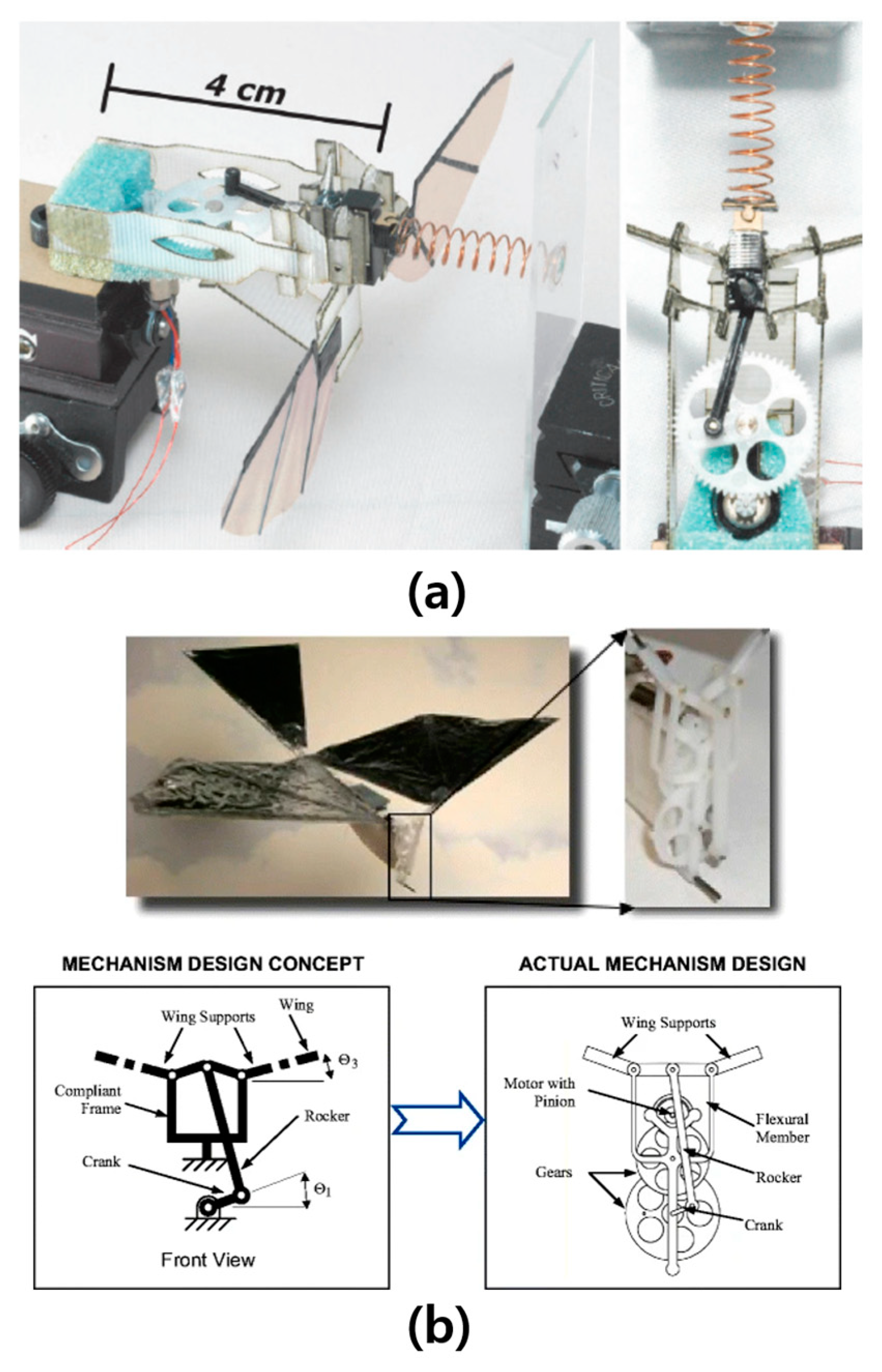
3.2. Classification of the Flapping Mechanism According to Strategy for Aerodynamic Performance Improvement

As mentioned above, flying animals combine a flapping motion with other motions to improve aerodynamic performance. Studies have been conducted to imitate these flight strategies and apply them to FWAVs. Some FWAVs add different motions to existing mechanisms, either passively or actively. Aerodynamic performance can be categorized into three types: thrust increase, lift/drag ratio increase, and flight efficiency increase. Most FWAVs focus on specific aerodynamic performance improvement according to flight environment and purpose, and these strategies are discussed below. This section can be a reference for selecting a flapping mechanism according to operational purposes.

3.2.1. Strategies for Increasing Thrust

FWAVs have been studied with the expectation that they can perform various missions by replacing existing fixed-wing UAVs. However, the performance and efficiency of FWAVs are currently inferior to those of actual flying animals or fixed-wing UAVs. Unlike fixed-wing UAVs, which have separate devices for generating thrust, FWAVs struggle to generate sufficient thrust because only one pair of wings generate both lift and thrust. Efficient generation of thrust is an important challenge in the development of FWAVs.
An effective way to generate thrust is to use twisting, as mentioned above. The twisting motion of a wing can be obtained by the multi-axis flapping mechanisms highlighted above. A one-axis flapping mechanism can also generate twisting motion by wing deformation from aerodynamic and inertial force. Therefore, even a simple mechanism can be used to generate thrust. Xue et al. [87] conducted a study to increase thrust by using wing deformation. To vary the deformation of the wing, the natural frequency was changed, and a static thrust measurement test was performed according to the different natural frequencies of the wing.
Research on increasing thrust using flapping mechanisms has also been undertaken. The flapping mechanism of Jiang et al. [65] combines a crank-rocker mechanism and an eccentric sphere mechanism, which can generate a figure-of-eight wing motion. Using this mechanism, thrust was increased by 64.3% compared to a one-axis mechanism that can only generate flapping motion.

3.2.2. Strategies for Increasing Lift/Drag Ratio

Wing folding or wrist flexing is used to increase the lift/drag ratio of FWAVs. During the downstroke, more lift can be generated by increasing the wing area, and during the upstroke, negative lift and drag can be reduced by decreasing the wing area.
Ryu et al. [88] developed a wrist flexing–flapping mechanism and searched the parameters to maximize the flapping amplitude. It was confirmed that lift increased compared to the proposed mechanism with a one-axis flapping mechanism. The flapping mechanism outlined by Wissa et al. (flapping–flexing mechanism) reduced energy consumption and increased lift through the compliant spine at the center of the wing [67]. In addition, Hoff et al. [58] achieved 89% increased lift compared to non-folding mechanisms by using their bat-inspired folding-flapping mechanism. Li et al. [84] proposed a bat-type flapping–folding mechanism. The flapping motion is implemented based on the rigid linkage mechanism, and the locking system fully spreads the wings during the downstroke, and controls the folding by retracting and expanding the wings during the upstroke. There is no prototype of the mechanism, but aerodynamic analysis has demonstrated an increase in average lift.
In addition, the wings of Festo’s BionicSwift [89] are separated in a similar manner to bird feathers to increase the lift/drag ratio. During the upstroke, individual feathers separate to allow air to flow and reduce drag. During the downstroke, the feathers stick together to increase lift.

3.2.3. Strategies for Increasing Flight Efficiency

Flying animals adopt a variety of flight strategies to increase flight efficiency. As mentioned earlier, gliding-flapping or bounding-flapping is a strategy for saving energy during flight. However, few FWAV models have implemented these strategies. Some studies have been conducted to develop strategies to reduce energy consumption through gliding flight. For example, Robird can stop flapping and transit to glide mode by using a latching mechanism [75,90]. Zhang et al. [91] proposed a mechanism that can transition to glide mode by adding a gear-locking mechanism to the mechanism that enables wrist flexing.
For small-sized birds, wings are intermittently attached to their body to reduce wing drag, thereby reducing energy consumption and performing efficient flight (flapping-bounding). However, it is difficult to find examples of this method being applied to FWAVs, mostly due to increased weight and complexity when the mechanism for flapping-bounding is applied to small avian-inspired FWAVs.
Some studies have been conducted that imitate flight strategies that reduce energy consumption by storing and releasing kinetic energy in the wing muscles during flapping. For the simulation model of the flapping mechanism using a linear spring (introduced in Section 3.1.1) [38], energy consumption was reduced by 30% compared to those without the spring. Hines et al. [56] developed a mechanism for realizing flapping motion by directly connecting springs and wings to each motor. A voltage is applied to the motors, and the flapping motion is implemented directly without going through linkages or mechanisms. The springs directly connected to the motors act as an elastic member and generate flapping motion using resonance. This method hold the advantages of reduced mass and reduced energy consumption.
In addition, research on developing mechanisms to increase stability or maneuverability have been conducted [92,93]. Some examples of flapping mechanisms according to strategies to improve aerodynamic performance are listed in Table 3.

4. Research Topics for Advanced FWAV

Engineers have made great progress and advances in FWAVs, mimicking the superior flight performance of flying animals. However, it is still insufficient to replace existing UAVs in specific missions. In this section, the issues of the mechanisms used in FWAVs are discussed, and future directions are proposed.
Novel Mechanism Design
As in the previous literature survey, most FWAVs have used simple mechanisms [95]. Additionally, due to the spatial limitations of the flapping mechanism, there are few examples of full implementation regarding the various wing motions of flying animals. Additional motion through a passive or active mechanism will increase aerodynamic performance, and the development of a flapping mechanism that can effectively implement various wing motions of flying animals is still needed in future research.
There are also very limited cases of using strategies that can increase flight efficiency, such as gliding-flapping. Research on the braking mechanism, control system, and transition flight are still required. In addition, most FWAVs do not have mechanisms for take-off and landing. Flying animals can stop flying and rest to save energy. Gomez-Tamm et al. [96] have designed claws driven by a shape-memory alloy allowing an FWAV to take-off. Although there are few cases that have applied this mechanism, efficient flight of FWAVs can be expected through future research.
DC motors have mostly been used to drive the large wings of avian-inspired FWAVs, and the weight of the mechanism is significant. Technologies such as piezo-electric motors play a significant role in reducing the weight of insect-inspired FWAVs. However, due to problems in transmission, torque, and efficiency, there are few cases of piezo-electric actuator application to avian-inspired FWAVs. Therefore, actuator technology itself or actuator selection technology is required.
In addition, it will be possible to increase the performance of the flapping mechanism through the development of manufacturing technology for sophisticated design, the use of lightweight and high-strength composite materials, and the use of 3D printing technology. Carollo et al. [97] used 3D printing technology to prototype a flapping mechanism. The mechanism is characterized by its single-component composition. It has the advantage of being light and easy to manufacture and replace. Although only a concept has been proposed, the technology applied to the mechanism in the paper can be applied to a flapping mechanism mimicking a small bird.
Mechanism design combined with aerodynamic analysis
According to the previous literature, the kinematic design parameters of most flapping mechanisms are selected in a way that imitates flying animals. For the flapping–flexing mechanism (e.g., such as Smartbird [78,79]), kinematic design parameters such as link length, angle, and angular velocity were randomly selected to mimic a real bird without considering the aerodynamic characteristics. The flapping motions of flying animals are clearly efficient (in the low Reynolds number range). However, since there is a large difference in the structural aspects, such as wing size and flexibility, between flying animals and FWAVs, the most efficient flapping motions differ. The optimal wing kinematics are different depending on the flight environment, which involves factors such as wing shape, flight speed, etc. [98,99]. Therefore, it is necessary to effectively predict unsteady aerodynamics according to the flapping motion and search for an efficient flapping motion in the initial FWAV design stage rather than designing a mechanism that simply mimics wing motions.
Recently, research has been conducted to design a flapping mechanism by combining aerodynamic analysis. Kalpathy et al. [100] proposed a model that can obtain lift and energy consumption according to link lengths by combining a kinematic model and the Quasi-Steady aerodynamic model. The link lengths of the mechanism were selected to maximize the lift/power ratio. This method resulted in a 73.8% reduction in energy consumption. It is currently rare to design a flapping mechanism in this way; however, if the flapping mechanism is designed based on the unsteady aerodynamic model that has proven to be reliable, an aerodynamic efficiency increase can be expected.
Mechanism design combining aerodynamic and structural analysis
Due to the limited payload capacity of FWAVs, reducing weight and satisfying the minimum structural requirements of a given flight environment are crucial. Fluid–structure interaction (FSI) analysis is required to confirm whether the structural performance satisfies the given constraints and to optimize structural requirements. In addition, fatigue analysis or an analysis to prove structural robustness is also required to achieve repeatable flight performance. In a flight situation, complex flow occurs, causing structural deformation in the FWAV. Since the wing is deformed by its generated aerodynamic force, thus changing its aerodynamic characteristics, the aerodynamic force changes according to the structure of the wing even with the same flapping mechanism. In addition, it is necessary to consider the effect of the aerodynamic force generated by the wing on the mechanism.
Truong et al. [101] reduced the mass of the gear by 25% while meeting the structural requirements through optimization, but did not consider the aerodynamic effect. There are a few cases in which FSI analysis has been performed on FWAVs. However, if an FWAV is developed based on FSI analysis, it can have increased payload capacity while remaining structurally robust.
Multidisciplinary optimal design of FWAV
Developing FWAVs remains a challenge due to the complexity and lack of well-established means to predict overall design performance. Suitable models must be established and combined to comprehensively predict FWAV performance. Most studies have mainly focused on optimizing only one aspect of flight; however, similar to general aircraft development, FWAVs also use complex systems combining various fields such as aerodynamics, structure, and vibration. Therefore, various technologies must be combined and developed to improve the overall flight performance of FWAVs.
Stanford et al. [102] designed a mechanism through topology optimization that minimizes the mass of the mechanism while maximizing the thrust generated by the complaint flapping mechanism. This process is meaningful in that it uses an integrated finite element model combining aerodynamics, structure, and inertial forces. Khan et al. [57] proposed an optimization technique (shown in Figure 9) that combined aerodynamic, vibration, and dynamic analysis that can satisfy the design requirements and the similar optimization scheme applied in the development of the FWAV prototype named Dove [44].
A well-established design process is required for the successful development of an FWAV, and if designed in consideration of various fields, it can replace existing UAVs and perform various missions.

5. Conclusions

Here, a review was conducted on the mechanisms utilized to achieve wing motion in FWAV. Flapping mechanisms were classified and analyzed according to wing motion and aerodynamic performance improvement strategy. The current research gaps found in flapping mechanism development were discussed, and future research directions were suggested. This review will provide guidance in the initial design step of FWAV flapping mechanisms.
FWAVs should be developed in a systematic way considering their overall system. Although the flapping mechanism is an important part of determining kinematics, most have been designed using arbitrary design parameters or by trial-and-error, and there are not many cases designed with aerodynamic analysis. Therefore, it is expected that FWAVs can be actively used in various fields if accompanied by an integrated design process in their initial development stage.

Author Contributions

Conceptualization, Y.-J.H., H.-H.Y., S.-G.L. and E.-H.L.; Investigation, Y.-J.H., H.-H.Y. and S.-G.L.; Resources, J.-H.H.; Writing—original draft, Y.-J.H. and J.-H.H.; Visualization, Y.-J.H. and E.-H.L.; Supervision, J.-H.H.; Project administration, J.-H.H.; Funding acquisition, J.-H.H. All authors have read and agreed to the published version of the manuscript.

Funding

This research was supported by Unmanned Vehicles Core Technology Research and Development Program through the National Research Foundation of Korea (NRF) and Unmanned Vehicle Advanced Research Center (UVARC) funded by the Ministry of Science and ICT, the Republic of Korea (2020M3C1C1A01083415).

Data Availability Statement

Not applicable.

Conflicts of Interest

The authors declare no conflict of interest.

Nomenclature

FWAVFlapping-Wing Air Vehicle,
UAVUnmanned Aerial Vehicle
CFDComputational Fluid Dynamics
UVLMUnsteady Vortex Lattice Method
FSIFluid–Structure Interaction
mMass
gGravitational acceleration
PRequired power
P0Estimated power outputs

References

  1. Shyy, W.; Aono, H.; Kang, C.-K.; Liu, H. An Introduction to Flapping Wing Aerodynamics; Cambridge University Press: London, UK, 2013; Volume 37. [Google Scholar]
  2. Dial, K.P.; Biewener, A.A.; Tobalske, B.W.; Warrick, D. Mechanical power output of bird flight. Nature 1997, 390, 67–70. [Google Scholar] [CrossRef]
  3. Lindhe Norberg, U.M. Structure, form, and function of flight in engineering and the living world. J. Morphol. 2002, 252, 52–81. [Google Scholar] [CrossRef] [PubMed]
  4. Han, J.-H.; Lee, J.-S.; Kim, D.-K. Bio-inspired flapping UAV design: A university perspective. In Proceedings of the 16th SPIE International Symposium Smart Structures + NDE, San Diego, CA, USA, 9–12 March 2009; pp. 466–477. [Google Scholar]
  5. Send, W.; Fischer, M.; Jebens, K.; Mugrauer, R.; Nagarathinam, A.; Scharstein, F. Artificial hinged-wing bird with active torsion and partially linear kinematics. In Proceedings of the 28th Congress of the International Council of the Aeronautical Sciences, Brisbane, Australia, 23–28 September; 2012; pp. 1148–1157. [Google Scholar]
  6. Keennon, M.; Klingebiel, K.; Won, H. Development of the nano hummingbird: A tailless flapping wing micro air vehicle. In Proceedings of the 50th AIAA Aerosp Sci Meet, Nashville, TN, USA, 9–12 January 2012; pp. 1–24. [Google Scholar]
  7. Shyy, W.; Kang, C.-k.; Chirarattananon, P.; Ravi, S.; Liu, H. Aerodynamics, sensing and control of insect-scale flapping-wing flight. Proc. R. Soc. A Math. Phys. Eng. Sci. 2016, 472, 20150712. [Google Scholar] [CrossRef] [Green Version]
  8. Chattaraj, N.; Ganguli, R. Mechatronic Approaches to Synthesize Biomimetic Flapping-Wing Mechanisms: A Review. Int. J. Aeronaut. Space Sci. 2022, 24, 105–120. [Google Scholar] [CrossRef]
  9. Chin, D.D.; Matloff, L.Y.; Stowers, A.K.; Tucci, E.R.; Lentink, D. Inspiration for wing design: How forelimb specialization enables active flight in modern vertebrates. J. R. Soc. Interface 2017, 14, 20170240. [Google Scholar] [CrossRef] [Green Version]
  10. Ward, T.A.; Rezadad, M.; Fearday, C.J.; Viyapuri, R. A review of biomimetic air vehicle research: 1984–2014. Int. J. Micro Air Veh. 2015, 7, 375–394. [Google Scholar] [CrossRef]
  11. Tobalske, B.; Dial, K. Flight kinematics of black-billed magpies and pigeons over a wide range of speeds. J. Exp. Biol. 1996, 199, 263–280. [Google Scholar] [CrossRef]
  12. Young, J.; Walker, S.M.; Bomphrey, R.J.; Taylor, G.K.; Thomas, A.L. Details of insect wing design and deformation enhance aerodynamic function and flight efficiency. Science 2009, 325, 1549–1552. [Google Scholar] [CrossRef] [Green Version]
  13. Berge, J.C.V. A comparative study of the appendicular musculature of the order Ciconiiformes. Am. Midl. Nat. 1970, 84, 289–364. [Google Scholar] [CrossRef]
  14. Altshuler, D.L.; Bahlman, J.W.; Dakin, R.; Gaede, A.H.; Goller, B.; Lentink, D.; Segre, P.S.; Skandalis, D.A. The biophysics of bird flight: Functional relationships integrate aerodynamics, morphology, kinematics, muscles, and sensors. Can. J. Zool. 2015, 93, 961–975. [Google Scholar] [CrossRef] [Green Version]
  15. Vazquez, R. The automating skeletal and muscular mechanisms of the avian wing (Aves). Zoomorphology 1994, 114, 59–71. [Google Scholar] [CrossRef]
  16. Brown, R. The flight of birds. Biol. Rev. 1963, 38, 460–489. [Google Scholar] [CrossRef]
  17. Riskin, D.K.; Bergou, A.; Breuer, K.S.; Swartz, S.M. Upstroke wing flexion and the inertial cost of bat flight. Proc. R. Soc. B Biol. Sci. 2012, 279, 2945–2950. [Google Scholar] [CrossRef] [PubMed] [Green Version]
  18. Norberg, U.M. Vertebrate Flight: Mechanics, Physiology, Morphology, Ecology and Evolution; Springer: Göteborg, Sweden, 2012; Volume 27. [Google Scholar]
  19. Kang, C.-K.; Aono, H.; Cesnik, C.E.; Shyy, W. Effects of flexibility on the aerodynamic performance of flapping wings. J. Fluid Mech. 2011, 689, 32–74. [Google Scholar] [CrossRef] [Green Version]
  20. Addo-Akoto, R.; Han, J.-S.; Han, J.-H. Roles of wing flexibility and kinematics in flapping wing aerodynamics. J. Fluids Struct. 2021, 104, 103317. [Google Scholar] [CrossRef]
  21. Wu, P.; Ifju, P.; Stanford, B. Flapping wing structural deformation and thrust correlation study with flexible membrane wings. AIAA J. 2010, 48, 2111–2122. [Google Scholar] [CrossRef]
  22. Ponitz, B.; Schmitz, A.; Fischer, D.; Bleckmann, H.; Brücker, C. Diving-flight aerodynamics of a peregrine falcon (Falco peregrinus). PLoS ONE 2014, 9, e86506. [Google Scholar] [CrossRef] [Green Version]
  23. Lentink, D.; Müller, U.; Stamhuis, E.; De Kat, R.; Van Gestel, W.; Veldhuis, L.; Henningsson, P.; Hedenström, A.; Videler, J.J.; Van Leeuwen, J.L. How swifts control their glide performance with morphing wings. Nature 2007, 446, 1082–1085. [Google Scholar] [CrossRef]
  24. Stowers, A.K.; Lentink, D. Folding in and out: Passive morphing in flapping wings. Bioinspir. Biomim. 2015, 10, 025001. [Google Scholar] [CrossRef] [Green Version]
  25. Phan, H.V.; Park, H.C. Mechanisms of collision recovery in flying beetles and flapping-wing robots. Science 2020, 370, 1214–1219. [Google Scholar] [CrossRef]
  26. Hedenström, A.; Johansson, L.C.; Spedding, G.R. Bird or bat: Comparing airframe design and flight performance. Bioinspir. Biomim. 2009, 4, 015001. [Google Scholar] [CrossRef] [PubMed]
  27. Tobalske, B.W.; Hedrick, T.L.; Biewener, A.A. Wing kinematics of avian flight across speeds. J. Avian Biol. 2003, 34, 177–184. [Google Scholar] [CrossRef]
  28. Hieronymus, T.L. Flight feather attachment in rock pigeons (Columba livia): Covert feathers and smooth muscle coordinate a morphing wing. J. Anat. 2016, 229, 631–656. [Google Scholar] [CrossRef] [PubMed] [Green Version]
  29. Tanaka, H.; Suzuki, H.; Kitamura, I.; Maeda, M.; Liu, H. Lift generation of hummingbird wing models with flexible loosened membranes. In Proceedings of the 2013 IEEE/RSJ International Conference on Intelligent Robots and Systems, Tokyo, Japan, 3–7 November 2013; pp. 3777–3783. [Google Scholar]
  30. Tobalske, B.W.; Warrick, D.R.; Clark, C.J.; Powers, D.R.; Hedrick, T.L.; Hyder, G.A.; Biewener, A.A. Three-dimensional kinematics of hummingbird flight. J. Exp. Biol. 2007, 210, 2368–2382. [Google Scholar] [CrossRef] [Green Version]
  31. Pennycuick, C.J. A wind-tunnel study of gliding flight in the pigeon Columba livia. J. Exp. Biol. 1968, 49, 509–526. [Google Scholar] [CrossRef]
  32. Tobalske, B.W. Hovering and intermittent flight in birds. Bioinspir. Biomim. 2010, 5, 045004. [Google Scholar] [CrossRef] [Green Version]
  33. Tobalske, B.W.; Hearn, J.W.; Warrick, D.R. Aerodynamics of intermittent bounds in flying birds. Exp. Fluids 2009, 46, 963–973. [Google Scholar] [CrossRef]
  34. Von Busse, R.; Hedenström, A.; Winter, Y.; Johansson, L.C. Kinematics and wing shape across flight speed in the bat, Leptonycteris yerbabuenae. Biol. Open 2012, 1, 1226–1238. [Google Scholar] [CrossRef] [Green Version]
  35. Hedenström, A.; Johansson, L.C. Bat flight: Aerodynamics, kinematics and flight morphology. J. Exp. Biol. 2015, 218, 653–663. [Google Scholar] [CrossRef] [Green Version]
  36. Pennycuick, C.J. Gliding flight of the dog-faced bat Rousettus aegyptiacus observed in a wind tunnel. J. Exp. Biol. 1971, 55, 833–845. [Google Scholar] [CrossRef]
  37. Pennycuick, C.J. Power requirements for horizontal flight in the pigeon Columba livia. J. Exp. Biol. 1968, 49, 527–555. [Google Scholar] [CrossRef]
  38. Madangopal, R.; Khan, Z.A.; Agrawal, S.K. Biologically inspired design of small flapping wing air vehicles using four-bar mechanisms and quasi-steady aerodynamics. J. Mech. Des. 2005, 127, 809–816. [Google Scholar] [CrossRef] [Green Version]
  39. Baek, S.S.; Ma, K.Y.; Fearing, R.S. Efficient resonant drive of flapping-wing robots. In Proceedings of the 2009 IEEE/RSJ International Conference on Intelligent Robots and Systems, St. Louis, MO, USA, 10–15 October 2009; pp. 2854–2860. [Google Scholar]
  40. Mueller, D.; Bruck, H.; Gupta, S. Measurement of thrust and lift forces associated with drag of compliant flapping wing for micro air vehicles using a new test stand design. Exp. Mech. 2010, 50, 725–735. [Google Scholar] [CrossRef]
  41. Lee, J.-S.; Lee, D.-K.; Han, J.-H. Ornitopter attitude estimation: Ground test. In Proceedings of the 2010 World Automation Congress, Kobe, Japan, 19–23 September 2010; pp. 1–6. [Google Scholar]
  42. Nguyen, Q.-V.; Chan, W.L.; Debiasi, M. Design, fabrication, and performance test of a hovering-based flapping-wing micro air vehicle capable of sustained and controlled flight. In Proceedings of the IMAV 2014: International Micro Air Vehicle Conference and Competition 2014, Delft, The Netherlands, 12–15 August 2014; pp. 18–25. [Google Scholar]
  43. Mazaheri, K.; Ebrahimi, A.; Karimian, S. Performance analysis of a flapping-wing vehicle based on experimental aerodynamic data. J. Aerosp. Eng. 2012, 25, 45–50. [Google Scholar] [CrossRef]
  44. Yang, W.; Wang, L.; Song, B. Dove: A biomimetic flapping-wing micro air vehicle. Int. J. Micro Air Veh. 2018, 10, 70–84. [Google Scholar] [CrossRef] [Green Version]
  45. Zhang, Y.; Wang, X.; Zhang, G.; Yang, J. Design and analysis of single-degree-of-freedom flapping wing mechanism based on UG. In Journal of Physics: Conference Series; IOP Publishing: Bristol, UK, 2020; p. 012060. [Google Scholar]
  46. Yang, L.-J.; Hsu, C.-K.; Han, H.-C.; Miao, J.-M. Light flapping micro aerial vehicle using electrical-discharge wire-cutting technique. J. Aircr. 2009, 46, 1866–1874. [Google Scholar] [CrossRef]
  47. Tsai, B.-J.; Fu, Y.-C. Design and aerodynamic analysis of a flapping-wing micro aerial vehicle. Aerosp. Sci. Technol. 2009, 13, 383–392. [Google Scholar] [CrossRef]
  48. Pan, E.; Chen, L.; Zhang, B.; Xu, W. A kind of large-sized flapping wing robotic bird: Design and experiments. In Proceedings of the Intelligent Robotics and Applications: 10th International Conference, ICIRA 2017, Wuhan, China, 16–18 August 2017; pp. 538–550. [Google Scholar]
  49. Zufferey, R.; Tormo-Barbero, J.; Guzmán, M.M.; Maldonado, F.J.; Sanchez-Laulhe, E.; Grau, P.; Pérez, M.; Acosta, J.Á.; Ollero, A. Design of the high-payload flapping wing robot e-flap. IEEE Robot. Autom. Lett. 2021, 6, 3097–3104. [Google Scholar] [CrossRef]
  50. Pan, E.; Xu, H.; Yuan, H.; Peng, J.; Xu, W. HIT-Hawk and HIT-Phoenix: Two kinds of flapping-wing flying robotic birds with wingspans beyond 2 meters. Biomim. Intell. Robot. 2021, 1, 100002. [Google Scholar] [CrossRef]
  51. Maglasang, J.; Goto, N.; Isogai, K. Development of bird-like micro aerial vehicle with flapping and feathering wing motions. Trans. Jpn. Soc. Aeronaut. Space Sci. 2008, 51, 8–15. [Google Scholar] [CrossRef] [Green Version]
  52. Sun, W.; Yu, J.; He, G.; Cai, Y. Study on transmission mechanism and flexible flapping wings of an underactuated flapping wing robot. J. Intell. Robot. Syst. 2022, 104, 19. [Google Scholar] [CrossRef]
  53. Yusoff, H.; Abdullah, M.; Mujeebu, M.A.; Ahmad, K. Development of flexible wings and flapping mechanism with integrated electronic control system, for micro air vehicle research. Exp. Tech. 2013, 37, 25–37. [Google Scholar] [CrossRef]
  54. Nguyen, T.A.; Phan, H.V.; Au, T.K.L.; Park, H.C. Experimental study on thrust and power of flapping-wing system based on rack-pinion mechanism. Bioinspir. Biomim. 2016, 11, 046001. [Google Scholar] [CrossRef] [PubMed]
  55. Yi, S.; Li, D.; Jiaqi, J.; Jinwu, X.; Wei, X. Design and experimental study of a new flapping wing rotor micro aerial vehicle. In Proceedings of the 2017 IEEE International Conference on Unmanned Systems, Miami, FL, USA, 27–29 October 2017; pp. 29–33. [Google Scholar]
  56. Hines, L.; Campolo, D.; Sitti, M. Liftoff of a motor-driven, flapping-wing microaerial vehicle capable of resonance. IEEE Trans. Robot. 2013, 30, 220–232. [Google Scholar] [CrossRef]
  57. Khan, Z.A.; Agrawal, S.K. Design and optimization of a biologically inspired flapping mechanism for flapping wing micro air vehicles. In Proceedings of the 2007 IEEE International Conference on Robotics and Automation, Rome, Italy, 10–14 April 2007; pp. 373–378. [Google Scholar]
  58. Hoff, J.; Ramezani, A.; Chung, S.-J.; Hutchinson, S. Optimizing the structure and movement of a robotic bat with biological kinematic synergies. Int. J. Robot. Res. 2018, 37, 1233–1252. [Google Scholar] [CrossRef] [Green Version]
  59. Chen, A.; Song, B.; Wang, Z.; Xue, D.; Liu, K. A Novel Actuation Strategy for an Agile Bioinspired FWAV Performing a Morphing-Coupled Wingbeat Pattern. IEEE Trans. Robot. 2022, 39, 452–469. [Google Scholar] [CrossRef]
  60. Furst, S.J.; Bunget, G.; Seelecke, S. Design and fabrication of a bat-inspired flapping-flight platform using shape memory alloy muscles and joints. Smart Mater. Struct. 2012, 22, 014011. [Google Scholar] [CrossRef]
  61. Żbikowski, R.; Galin’ski, C.; Pedersen, C.B. Four-bar linkage mechanism for insectlike flapping wings in hover: Concept and an outline of its realization. J. Mech. Des. 2005, 127, 817–824. [Google Scholar] [CrossRef]
  62. Hu, Y.; Ru, W.; Liu, Q.; Wang, Z. Design and Aerodynamic Analysis of Dragonfly-like Flapping Wing Micro Air Vehicle. J. Bionic Eng. 2022, 19, 343–354. [Google Scholar] [CrossRef]
  63. Ji, B.; Zhu, Q.; Guo, S.; Yang, F.; Li, Y.; Zhu, Z.; Chen, S.; Song, R.; Li, Y. Design and experiment of a bionic flapping wing mechanism with flapping–twist–swing motion based on a single rotation. AIP Adv. 2020, 10, 065018. [Google Scholar] [CrossRef]
  64. Galiński, C.; Żbikowski, R. Insect-like flapping wing mechanism based on a double spherical Scotch yoke. J. R. Soc. Interface 2005, 2, 223–235. [Google Scholar] [CrossRef] [PubMed] [Green Version]
  65. Jiang, S.; Hu, Y.; Li, Q.; Ma, L.; Wang, Y.; Zhou, X.; Liu, Q. Design and analysis of an innovative flapping wing micro aerial vehicle with a figure eight wingtip trajectory. Mech. Sci. 2021, 12, 603–613. [Google Scholar] [CrossRef]
  66. Kim, D.-K.; Kim, H.-I.; Han, J.-H.; Kwon, K.-J. Experimental investigation on the aerodynamic characteristics of a bio-mimetic flapping wing with macro-fiber composites. J. Intell. Mater. Syst. Struct. 2008, 19, 423–431. [Google Scholar] [CrossRef]
  67. Wissa, A.; Tummala, Y.; Hubbard, J., Jr.; Frecker, M. Passively morphing ornithopter wings constructed using a novel compliant spine: Design and testing. Smart Mater. Struct. 2012, 21, 094028. [Google Scholar] [CrossRef]
  68. Hoff, J.; Jeon, N.; Li, P.; Kim, J. Bat Bot 2.0: Bio-inspired anisotropic skin, passive wrist joints, and redesigned flapping mechanism. In Proceedings of the 2021 IEEE/RSJ International Conference on Intelligent Robots and Systems (IROS), Prague, Czech Republic, 27 September–1 October 2021; pp. 8424–8430. [Google Scholar]
  69. Jitsukawa, T.; Adachi, H.; Abe, T.; Yamakawa, H.; Umezu, S. Bio-inspired wing-folding mechanism of micro air vehicle (MAV). Artif. Life Robot. 2017, 22, 203–208. [Google Scholar] [CrossRef]
  70. Kumar, D.; Goyal, T.; Kamle, S.; Mohite, P.; Lau, E. Realisation and testing of novel fully articulated bird-inspired flapping wings for efficient and agile UAVs. Aeronaut. J. 2021, 125, 2114–2148. [Google Scholar] [CrossRef]
  71. Ruiz, C.; Acosta, J.Á.; Ollero, A. Optimal Elastic Wing for Flapping-Wing Robots Through Passive Morphing. IEEE Robot. Autom. Lett. 2022, 8, 608–615. [Google Scholar] [CrossRef]
  72. Colorado, J.; Barrientos, A.; Rossi, C.; Breuer, K.S. Biomechanics of smart wings in a bat robot: Morphing wings using SMA actuators. Bioinspir. Biomim. 2012, 7, 036006. [Google Scholar] [CrossRef] [PubMed] [Green Version]
  73. Ma, N.; Zhou, X.; He, G.; Yu, J. Design and analysis of a bat-like active morphing wing mechanism. In Proceedings of the International Design Engineering Technical Conferences and Computers and Information in Engineering Conference, Charlotte, NC, USA, 5 December 2016; p. V05AT07A054. [Google Scholar]
  74. Savastano, E.; Perez-Sanchez, V.; Arrue, B.; Ollero, A. High-Performance Morphing Wing for Large-Scale Bio-Inspired Unmanned Aerial Vehicles. IEEE Robot. Autom. Lett. 2022, 7, 8076–8083. [Google Scholar] [CrossRef]
  75. Folkertsma, G.A.; Straatman, W.; Nijenhuis, N.; Venner, C.H.; Stramigioli, S. Robird: A robotic bird of prey. IEEE Robot. Autom. Mag. 2017, 24, 22–29. [Google Scholar] [CrossRef]
  76. Chellapurath, M.; Noble, S.; Sreejalekshmi, K. Design and kinematic analysis of flapping wing mechanism for common swift inspired micro aerial vehicle. Proc. Inst. Mech. Eng. C J. Mech. Eng. Sci. 2021, 235, 4026–4036. [Google Scholar] [CrossRef]
  77. Xu, K.; Liu, H. Design of a Compliant Flapping-Wing Mechanism with Flapping–Twist–Swing Motion. IEEE/ASME Trans. Mechatron. 2022, 27, 5197–5207. [Google Scholar] [CrossRef]
  78. Jiang, H.; Zhou, C.; Xie, P. Design and kinematic analysis of seagull inspired flapping wing robot. In Proceedings of the 2016 IEEE International Conference on Information and Automation (ICIA), Ningbo, China, 1–3 August 2016; pp. 1382–1386. [Google Scholar]
  79. Kim, S.; Kim, M.; Kim, S.; Suk, J. Design, fabrication, and flight test of articulated ornithopter. In Proceedings of the 10th International Micro Air Vehicles Conference, Melbourne, Australia, 17–23 November 2018; pp. 1–6. [Google Scholar]
  80. Chand, A.N.; Kawanishi, M.; Narikiyo, T. Design Analysis Modelling and Experimental Validation of a Bird-like Flapping-Wing Flying Robot. In Proceedings of the IMAV 2014 International Micro Air Vehicle Conference and Competition, Delft, The Netherlands, 12–15 August 2014; pp. 12–15. [Google Scholar]
  81. Stopforth, R.; Bright, G. MechaBird: A biological inspired mechatronics bird for the evaluation of flight characteristics. In Proceedings of the 2015 IEEE International Conference on Automation Science and Engineering (CASE), Gothenburg, Sweden, 24–28 August 2015; pp. 335–341. [Google Scholar]
  82. Festo. BionicFlyingFox. Available online: https://www.festo.com/us/en/e/about-festo/research-and-development/bionic-learning-network/highlights-from-2015-to-2017/bionicflyingfox-id_32755/ (accessed on 1 April 2023).
  83. Bie, D.; Li, D.; Xiang, J.; Li, H.; Kan, Z.; Sun, Y. Design, aerodynamic analysis and test flight of a bat-inspired tailless flapping wing unmanned aerial vehicle. Aerosp. Sci. Technol. 2021, 112, 106557. [Google Scholar] [CrossRef]
  84. Li, Y.; Yang, W.; Chen, A.; Zhang, R. Mechanism Design and Aerodynamic Research of Retractable Folding Flapping Wing. In Proceedings of the 32th Congress of the International Council of the Aeronautical Sciences, Shanghai, China, 6–10 September 2021. [Google Scholar]
  85. Wang, C.; Zhou, C.; Zhang, X.; Liu, C. An optimization on single-crank-double-rocker flapping wing mechanism. In Proceedings of the 2010 Fourth International Conference on Genetic and Evolutionary Computing, Shenzhen, China, 13–15 December 2010; pp. 337–340. [Google Scholar]
  86. Dewangan, B.; Pradhan, D.; Roy, H. Bioinspired flapping wing UAV and its kinematic analysis—A novel approach. Proc. Inst. Mech. Eng. Part K J. Multi-Body Dyn. 2022, 236, 570–587. [Google Scholar] [CrossRef]
  87. Xue, D.; Song, B. Tuning the Deformation of Flapping Wing to Improve the Flight Efficiency of Dove FWMAV. J. Aerosp. Eng. 2021, 34, 04021069. [Google Scholar] [CrossRef]
  88. Ryu, S.W.; Lee, J.G.; Kim, H.J. Design, fabrication, and analysis of flapping and folding wing mechanism for a robotic bird. J. Bionic Eng. 2020, 17, 229–240. [Google Scholar] [CrossRef]
  89. Ackerman, E. Festo’s New Bio-Inspired Robots Include a Feathery Bionic Bird. Available online: https://spectrum.ieee.org/festo-bioinspired-robots-bionicswift (accessed on 1 April 2023).
  90. Straatman, W. Developing an Autopilot for the Peregrine Falcon Robird. Master’s Thesis, University of Twent, Enschede, The Netherlands, 2014. [Google Scholar]
  91. Zhang, H.; Liu, Z. Design and Research on Flapping Mechanism of Biomimetic Albatross. In Journal of Physics: Conference Series; IOP Publishing: Bristol, UK, 2022; p. 012006. [Google Scholar]
  92. Karásek, M.; Muijres, F.T.; De Wagter, C.; Remes, B.D.; De Croon, G.C. A tailless aerial robotic flapper reveals that flies use torque coupling in rapid banked turns. Science 2018, 361, 1089–1094. [Google Scholar] [CrossRef] [Green Version]
  93. Phan, H.V.; Aurecianus, S.; Kang, T.; Park, H.C. KUBeetle-S: An insect-like, tailless, hover-capable robot that can fly with a low-torque control mechanism. Int. J. Micro Air Veh. 2019, 11, 1756829319861371. [Google Scholar] [CrossRef] [Green Version]
  94. Zhu, Z.; Song, B.; Xue, D. Design and Verification of Large-Scaled Flapping Wings for High Altitude Environment. Appl. Sci. 2022, 12, 5140. [Google Scholar] [CrossRef]
  95. Yousaf, R.; Shahzad, A.; Qadri, M.M.; Javed, A. Recent advancements in flapping mechanism and wing design of micro aerial vehicles. Proc. Inst. Mech. Eng. C J. Mech. Eng. Sci. 2021, 235, 4425–4446. [Google Scholar] [CrossRef]
  96. Gomez-Tamm, A.E.; Perez-Sanchez, V.; Arrue, B.C.; Ollero, A. SMA actuated low-weight bio-inspired claws for grasping and perching using flapping wing aerial systems. In Proceedings of the 2020 IEEE/RSJ International Conference on Intelligent Robots and Systems (IROS), Las Vegas, NV, USA, 24 October 2020–24 January 2021; pp. 8807–8814. [Google Scholar]
  97. Carollo, G.; Ingrassia, T.; Pantano, A. Design of a low cost 3D printable single-component compliant mechanism for FWMAV’s wing actuation. In Proceedings of the Design Tools and Methods in Industrial Engineering II: Proceedings of the Second International Conference on Design Tools and Methods in Industrial Engineering, ADM 2021, Rome, Italy, 9–10 September 2021; Springer International Publishing: Berlin/Heidelberg, Germany, 2021; pp. 39–49. [Google Scholar]
  98. Bhattacharjee, D.; Paranjape, A.A.; Pant, R.S. Optimization of the spanwise twist of a flapping wing for bird-sized aircraft using a quasi-steady aerodynamic model. Int. J. Aeronaut. Space Sci. 2019, 20, 571–583. [Google Scholar] [CrossRef]
  99. Kumaresan, A.; Subramanian, L.G. Optimal flapping wing shape and kinematics are different for different flight velocities: An analysis on local relative wind. Eng. Res. Express 2021, 3, 015023. [Google Scholar] [CrossRef]
  100. Kalpathy Venkiteswaran, V.; Su, H. Optimization of mechanism design of flapping wing MAV. In Proceedings of the 55th AIAA/ASMe/ASCE/AHS/SC Structures, Structural Dynamics, and Materials Conference, National Harbor, MD, USA, 13–17 January 2014; pp. 13–17. [Google Scholar]
  101. Van Truong, T.; Kureemun, U.; Tan, V.B.C.; Lee, H.P. Study on the structural optimization of a flapping wing micro air vehicle. Struct. Multidiscip. Optim. 2018, 57, 653–664. [Google Scholar] [CrossRef]
  102. Stanford, B.; Beran, P. Conceptual design of compliant mechanisms for flapping wings with topology optimization. AIAA J. 2011, 49, 855–867. [Google Scholar] [CrossRef]
Figure 1. Aerodynamic characteristics of flying animals, Reynolds number vs. reduced frequency (adapted from [4]; photograph from Brian Gratwicke and open-source photographs).
Aerospace 10 00554 g001
Figure 2. Wing motions of flying animals (a) wing folding, (b) wing twisting, and (c) wrist flexing. Reprinted with permission from Ref. [14]. 2015, Canadian Science Publishing.
Aerospace 10 00554 g002
Figure 3. Classification of flapping mechanism: one-axis flapping mechanism vs. multi-axis flapping mechanism [5,24,38,39,40,41,42,43,44,45,46,47,48,49,50,51,52,53,54,55,56,57,58,59,60,61,62,63,64,65,66,67,68,69,70,71,72,73,74,75,76,77,78,79,80,81,82,83,84].
Aerospace 10 00554 g003
Figure 4. Rigid mechanism (a) four-bar planar linkage mechanism (double-crank double rocker mechanism) (b) four-bar planar linkage mechanism (single-crank double rocker mechanism) (c) four-bar spatial linkage mechanism (d) slide-crank mechanism (e) scotch-yoke mechanism.
Aerospace 10 00554 g004
Figure 5. Compliant mechanism (a) flexible joint. Reprinted with permission from Ref. [39]. 2009, IEEE. (b) flexible frame. Reprinted with permission from Ref. [40]. 2009, Springer Nature.
Aerospace 10 00554 g005
Figure 6. Wing folding linkage mechanism (a) during downstroke (b) during upstroke.
Aerospace 10 00554 g006
Figure 7. Twisting linkage mechanism (a) twisting motion mechanism (adapted from [61]) (b) structural twisting mechanism (adapted from [62]).
Aerospace 10 00554 g007
Figure 8. Wrist flexing linkage mechanism (a) during downstroke (b) during upstroke.
Aerospace 10 00554 g008
Figure 9. Diagram of flapping mechanism design process [44,57].
Aerospace 10 00554 g009
Table 1. Classification of one-axis flapping mechanism.
TypeMechanismRefs.
Rigid mechanismFour-bar planar linkage mechanism double-crank double-rocker[41,42,43]
Four-bar planar linkage mechanism single-crank double-rocker[44,45,46,47]
Four-bar spatial linkage mechanism[48,49,50,51,52]
Slide-crank mechanism[53,54]
Scotch-yoke mechanism[55]
Compliant mechanismFlexible joint[38,39,56,57]
Flexible frame[40]
Table 2. Classification of multi-axis flapping mechanism.
MotionTypeMechanismRefs.
Wing foldingPassive *Rigid mechanism[24,58,68,69]
Compliant mechanism[71]
Active **Rigid mechanism[59,84]
Compliant mechanism[60,72,73,74]
TwistingPassiveRigid mechanism[61,62,63,64,65,75,76]
Compliant mechanism[57,77]
ActiveRigid mechanism[5,70,78]
Compliant mechanism[66]
Wrist flexingPassiveRigid mechanism[5,78,79,80,81,82,83]
Compliant mechanism[67,68]
ActiveRigid mechanism[70]
Compliant mechanism-
* passive: Different motions occur simultaneously while flapping without increasing the degree of freedom. ** active: As the degree of freedom increases, an additional actuator is required, and individual control is possible.
Table 3. Flight performance improvement strategy and contribution.
ObjectiveSpan
[mm]
Weight
[g]
Wing MotionContributionValidationRef.
Thrust640-FlappingThrust was increased by adjusting the natural frequency of the wing.Inertial force measurement test[87]
Thrust29024.8Flapping and
twisting
Thrust was increased compared to the mechanism that cannot generate twisting.Wind tunnel test[65]
Thrust9401500Flapping, wing folding, and feathered wingThrust was increased due to the wing shape changing by the feathers.Inertial force measurement test[69]
Lift/Drag Ratio53079Flapping and wing foldingDrag was reduced due to wing folding.Wind tunnel test[72]
Lift/Drag Ratio400-Flapping and wrist flexingLift was increased compared to the mechanism that cannot bend.Inertial force measurement test[88]
Lift/Drag Ratio16001100FlappingLift was increased by increasing the stiffness of the inner wing.CFD analysis, wind tunnel test and outdoor flight test[94]
Lift/Drag Ratio1500650Flapping and wing foldingLift was increased by searching the parameters of the compliant mechanism with aerodynamic analysis.Indoor flight test[71]
Lift/Drag Ratio & Flight efficiency--Flapping and wrist flexingMore lift was generated compared to the case without the complaint spine (45% energy consumption reduction; 16% lift increase).Inertial force measurement test[67]
Flight efficiency2000650Flapping and wing foldingBy using foldable and flexible wing, it can be driven at a lower flapping frequency and energy consumption can be reduced.UVLM analysis, indoor and outdoor flight test [74]
Disclaimer/Publisher’s Note: The statements, opinions and data contained in all publications are solely those of the individual author(s) and contributor(s) and not of MDPI and/or the editor(s). MDPI and/or the editor(s) disclaim responsibility for any injury to people or property resulting from any ideas, methods, instructions or products referred to in the content.

