Article

A Novel Disturbance-Free-Payload Satellite Design for High-Precision Collaborative Observation

1
School of Automation Science and Engineering, Xi’an Jiaotong University, Xi’an 710049, China
2
School of Electrical Engineering and Automation, Xiamen University of Technology, Xiamen 361024, China
3
Shanghai Satellite Engineering Institute, Shanghai 201109, China
*
Author to whom correspondence should be addressed.
Aerospace 2023, 10(6), 527; https://doi.org/10.3390/aerospace10060527
Submission received: 3 May 2023 / Revised: 26 May 2023 / Accepted: 30 May 2023 / Published: 1 June 2023
(This article belongs to the Special Issue Advanced Small Satellite Technology)

Abstract

:
High-precision collaborative observation is urgently needed due to the increasing demands of space science missions. Based on a conventional DFP (disturbance-free-payload) configuration, this paper presents a novel DFP that has great potential to deal with collaborative observation missions. The novel DFP system is developed, in which two or more payloads are installed via a non-contact unit and installed parallel configuration. Thus, the novel design is a multibody dynamics system. With the incorporation of the dynamics of the flexible umbilical between the PMs (payload modules) and SM (support module), the six-degrees-of-freedom multibody rigid–flexible dynamics of the whole system are derived. To verify the effectiveness of the novel DFP design in a collaborative observation mission, a multi-loop controller is designed for an inertial Earth collaborative observation mission. Simulation studies are conducted, which indicate that the proposed design can complete collaborative observation and achieve high precision.

1. Introduction

High-precision pointing performance, i.e., pointing accuracy and pointing stability, is urgently needed for sensitive payloads boarding on spacecraft. For instance, the LISA (Laser Interferometer Space Antenna), which is dedicated to gravitational detection [1,2], imposes relative displacement precision with 10 pm / Hz [3]. Aiming at detecting supermassive black-hole mergers and extreme mass ratio inspirals, the Chinese space mission Taiji requires position noise lower than 8 pm / Hz and acceleration noise lower than 3 × 10 15 ms 2 / Hz [4]. To control micro-vibrations transmitted from spacecraft platforms to sensitive payloads [5], researchers and institutes propose passive, active, hybrid, and semi-active vibration control methods [6,7,8,9,10]. Utilizing a flywheel actuator, Ref. [11] investigated a novel active vibration suppression approach for flexible spacecraft during attitude maneuvering. Based on an NREDO (noise reduction extended disturbance observer), the controller designed in Ref. [12] achieved the improved attitude stabilization performance of a flexible spacecraft. With the incorporation of a fuzzy disturbance observer and terminal sliding mode control strategy, the controller designed in Ref. [13] outperformed a conventional controller in chattering reduction and fast convergence speed. The above methods can effectively decrease disturbances. However, it is beyond these methods’ ability to satisfy the vibration suppression requirements proposed by modern and future space missions. To deal with this challenge, a spacecraft configuration known as a DFP (disturbance-free payload) is proposed by Pedreiro [14,
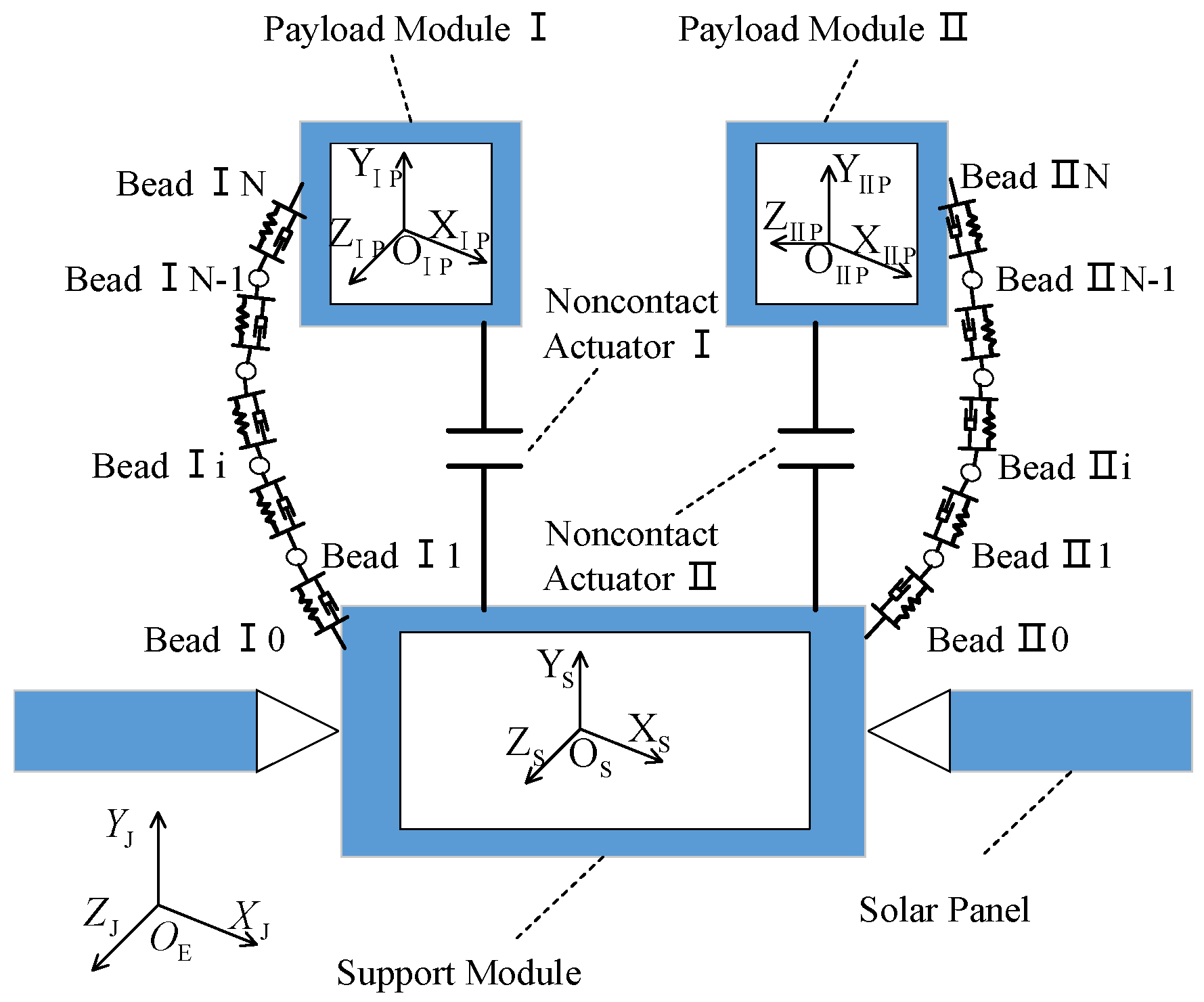
15]. In contrast with traditional spacecraft configuration, a sensitive payload in a DFP configuration is separated from the spacecraft platform. The resulting two parts, i.e., the SM (support module) and PM (payload module), are connected via a noncontact actuator. It is the noncontact design that provides the extremely high vibration isolation performance and, therefore, guarantees high-precision pointing performance for the sensitive payload. Recent studies concerning DFPs focused on precise dynamics building and control of the DFP system. With the incorporation of a bead model and the flexible dynamics of the support module, Ref. [16] investigated the impact of umbilical and flexible dynamics on the pointing performance of the DFP system. Based on static and dynamic models of flexible cable, Ref. [17] investigated the dynamic transmission characteristics of flexible cable. Ref. [18] utilized the model predictive control method to reduce the collision probability between the payload module and support module. It is evident that the aforementioned DFP-related studies considered only the payload module.
In spite of the high-precision pointing performance, collaborative observation has received great attention. Observation satellites, such as Earth observation and solar observation satellites, put forward higher requirements in terms of spatial coverage and spatial resolution. The conventional observation mode, i.e., a single satellite, makes it difficult to conduct continuous observation [19]. To meet the high-precision observation requirement, observation results obtained from different satellites, or results obtained from one satellite but at different times, are needed [20]. It is obvious that the conventional observation mode is time-consuming and has a high cost. To tackle this problem, a satellite with multiple payloads is proposed and studied. Ref. [21] introduced the 3Cat-1 project, whose main scope is to develop, construct, assemble, test and launch into Earth orbit a CubeSat with as many as seven different types of payloads. Through scientific experiments, the satellite demonstrated its capabilities as a cost-effective platform to conduct scientific experiments. Satellites launched by the Geostationary Operational Environmental Satellite-16 program carried two payloads [22]. In addition, the O/OREOS (Organism/Organic Exposure to Orbital Stresses) nanosatellite completed a multi-payload technology demonstration [23].
Although the conventional DFP configuration can provide a payload with high-precision pointing performance, the mode of a single payload greatly limits its multi-target detection capability. Multi-target detection might be a concern in future space missions. Moreover, to the best of the authors’ knowledge, this is the first attempt to investigate the collaborative observation capability of a DFP system.
This paper is dedicated to realizing the collaborative observation capability of a DFP system, and its main contributions lie in the following: (1) a novel DFP system that is potentially capable of collaborative observation is designed, and (2) the six-degrees-of-freedom multibody rigid–flexible dynamics of the novel DFP system are derived.
This paper is organized as follows. Section 2 presents a detailed description of the novel DFP system and discusses the difference between a conventional DFP system and the novel DFP system under study. Section 3 details the coordinate system and vectors used in this paper. Section 4 analyzes the forces and moments acting on the system. The six-degrees-of-freedom multibody rigid–flexible dynamics of the novel DFP system are established in Section 5. The control system for the DFP system is designed in Section 6, which is followed by simulation studies in Section 7. Finally, conclusions are drawn in Section 8.

2. Design of the Novel DFP System

A conventional DFP system is shown in Figure 1. The conventional DFP configuration consists of only one payload–umbilical–noncontact actuator unit. The umbilical, which is utilized for fluid, data and energy transfer between the SM and PM, is discretized into multiple beads. Adjacent beads are connected via a spring unit.
In order to enhance its multi-target observation ability, the novel DFP configuration system in which two payloads are installed in a parallel style is shown in Figure 2. Compared with the conventional DFP system in Figure 1, the novel DFP system in Figure 2 has two sets of payload–umbilical–actuator units. To make it clear, the sets of payload–umbilical–actuator units are denoted as I and II, respectively.

3. Coordinate System and Vector Description

3.1. Coordinate System

As is shown in Figure 2, the coordinate system in this paper includes four reference frames.
O J X J Y J Z J is the J2000 Equatorial Reference Frame. O J is the origin of the reference frame, which lies at the Earth’s center of mass. The x-axis points toward the vernal equinox, while the y-axis is 90° to the east in the equatorial plane. The z-axis directs along the north pole [16].
O S X S Y S Z S is a body-fixed frame with its origin fixed on the center of the SM and three axes along the principal central axes of the inertia of the SM.
O P X P Y P Z P and O P X P Y P Z P are counterparts of O S X S Y S Z S associated with Payload Module I and Payload Module II.

3.2. Vector Description

Figure 3 illustrates a detailed vector description of the novel DFP system.
The vectors and their definitions are presented in Table 1.
As can been seen in Table 1, ρ S i = r i d S is the relative position vector between Bead Ii and SM as measured along O S - X S Y S Z S . Moreover, ρ S i = r i d S is the relative position vector between Bead IIi and SM as measured along O S - X S Y S Z S . According to Figure 3 and Table 1, the relationship between r i , r P and d P is given below:
r P = d P + r i , when i = N

4. Forces and Moments Acting on the System

The novel DFP system comprises one support module, two umbilicals and two payloads. The forces and moments acting on these five parts are analyzed in this section.

4.1. Forces and Moments Acting on PM I

The forces and moments acting on PM I are summarized in Table 2.
In Table 2, the force resulting from Earth’s gravity ( F Pg ) can be expressed as:
F Pg = M P U P
U P in the above equation is the Earth’s gravitational potential, which can be expressed as a summation of all the possible spherical harmonics [16]. In addition, M P is the mass of PM I.
Here, we assume the DFP system under study operates at a low Earth orbit. Thus, atmospheric drag plays the major part, whereas other disturbing forces such as radiation force can be neglected.
F Pd is expressed as:
F P d = 1 2 C d S d ρ v P r v P r
where C d is the drag coefficient, S d is the reference area, ρ is the atmospheric density, v Pr is PM I’s velocity relative to the rotating atmosphere, and v P r is the norm of v P r [16].
PM I is immune to disturbance onboard the SM. Therefore, the gravity gradient moment is the only concerning source of disturbance. The disturbing moments applying on PM I are presented as in [24,25]:
T Pd = 3 μ r P b 5 I P z I P y r P y b r P z b I P x I P z r P x b r P z b I P y I P x r P x b r P y b
where μ is the standard gravitational parameter and r P b r P x b , r P y b , r P z b represents three components of r P resolved along O P X P Y P Z P .
The umbilical force acting on PM I can be expressed as:
F P u = k s ρ N l ¯ s ρ N ρ N + c d v N v N 1
where ρ 1 is the norm of ρ 1 , k Ι s and c Ι d are the stiffness and damping coefficients of the spring/damper unit, and l ¯ Ι s is the length of Umbilical I when the spring/damper unit reaches a state of equilibrium, i.e., a state in which the spring/damper unit has no deformation. As is shown in the equation, the umbilical force acting on PM I consists of two parts. The expression of the first part, i.e., k s ρ N l ¯ s ρ N ρ N , is generated by the adjacent spring, whose expression can be found in Ref. [16]. In addition, the second part, c d v N v N 1 , originates from the adjacent damper.
The umbilical moment acting on PM I is given as:
T Pu = d P × F Pu
The control forces and control torques are designed according to the control goal.

4.2. Forces and Moments Acting on PM II

PM II is susceptible to the forces and moments listed in Table 3.
By substituting the subscript ‘I’ with ‘II’ in Equations (2)~(6), the forces and moments acting on PM II can be expressed as:
F Pg = M P U P
F P d = 1 2 C d S d ρ v P r v P r
T Pd = 3 μ r P b 5 I P z I P y r P y b r P z b I P x I P z r P x b r P z b I P y I P x r P x b r P y b
F P u = k s ρ N l ¯ s ρ N ρ N + c d v N v N 1
T Pu = d P × F Pu

4.3. Forces and Moments Acting on SM

SM is subject to the forces and moments listed in Table 4.
The expressions of the forces and moments in Table 4 are given as:
F Sg = M S U S
F Sd = 1 2 C d S d ρ v Sr v Sr
T Sd = 3 μ r S b 5 I S z I S y r S y b r S z b I S x I S z r S x b r S z b I S y I S x r S x b r S y b + a 1 a 2 a 3 N m + b 1 cos ω n t b 2 sin ω n t b 3 sin ω n t N m
F Ι Su = k Ι s ρ Ι 1 l ¯ Ι s ρ Ι 1 ρ Ι 1
T Ι Su = d Ι S × F Ι Su
F Su = k s ρ 1 l ¯ s ρ 1 ρ 1
T Su = d S × F Su
F Ι Sin t = F Ι Pc
T Ι Sin t = T Ι Pc + ρ Ι r × F Ι Sin t
F Sin t = F Pc
T Sin t = T Pc + ρ r × F Sin t

4.4. Forces Acting on Umbilical I

Both umbilicals in Figure 2 are discretized into beads connected to the spring/damper unit. The forces acting on Bead Ii are listed in Table 5.
The expressions of F i g and F B i are presented below:
F Ι ig = M Ι i U Ι i
F Ι Bi = k Ι s ρ Ι i + 1 l ¯ Ι s ρ Ι i + 1 ρ Ι i + 1 k Ι s ρ Ι i l ¯ Ι s ρ Ι i ρ Ι i

4.5. Forces Acting on Umbilical II

The forces acting on Bead IIi are listed in Table 6.
By substituting the subscript ‘I’ with ‘II’ in (23)~(24), the forces acting on Bead IIi can be expressed as:
F ig = M i U i
F Bi = k s ρ i + 1 l ¯ s ρ i + 1 ρ i + 1 k s ρ i l ¯ s ρ i ρ i

5. Motion Equations of the Novel DFP System

According to the forces and moments analysis in the last section, the motion equations of the novel DFP system can be derived via Newtonian mechanics. Motion equations consist of kinematic equations and dynamic equations.

5.1. Motion Equations of PM I

The kinematic equations of PM I are given as follows:
r ˙ P = v P q ˙ P = 1 2 q P ϖ P
The dynamic equations of PM I can be expressed as:
M P v ˙ P = F Pg + F Pd + F Pu + F Pc I P ω ˙ P = ω P × I P ω P + T Pd + T Pu + T Pc
where M P and I P are the mass and inertial tensor of PM II, respectively; v P is the translational velocity; while ω P and ϖ P = 0 ω P T T are the angular velocity and its expanded form, respectively. The superscript T denotes the transpose operator. q P = q P 0 q P v T T is the quaternion of PM I relative to the inertial frame in which q P 0 is the scalar part and q P v is the vector part. The rotation sequence ‘Z-Y-X’ is used in this paper with three corresponding Euler angles: ψ P , θ P and φ P .

5.2. Motion Equations of PM II

By substituting the subscript ‘I’ with ‘II’ in Equations (27) and (28), the kinematic and dynamic equations of PM II can be obtained:
r ˙ P = v P q ˙ P = 1 2 q P ϖ P
M P v ˙ P = F Pg + F Pd + F Pu + F Pc I P ω ˙ P = ω P × I P ω P + T Pd + T Pu + T Pc

5.3. Motion Equations of SM

The kinematic equations of SM are given as follows:
r ˙ S = v S q ˙ S = 1 2 q S ϖ S
The dynamic equations of SM can be expressed as:
M S v ˙ S + B t η ¨ = F Sg + F Sd + F Su + F Su I S ω ˙ S + B r η ¨ = ω S × I S ω S + T Sd + T Su + T Su + T Sc η ¨ + 2 ζ Ω η ˙ + Ω 2 η + B t T a S + B r T ω ˙ S = 0
in which η denotes the modal coordinates; ζ and Ω represent the modal damping ratio and fundamental frequencies of the solar panels, respectively; while B t and B r are the translational matrix and rotational coupling matrix, respectively, which represent the coupling effect between the solar panels and SM.

5.4. Motion Equations of BEAD Ii

The kinematic and dynamic equations of Bead Ii can be given as:
v i = r ˙ i
M i v ˙ i = F ig + k s ρ i + 1 l s ρ i + 1 ρ i + 1 k s ρ i l s ρ i ρ i

5.5. Motion Equations of BEAD IIi

By substituting the subscript ‘I’ with ‘II’ in Equations (33) and (34), the kinematic and dynamic equations of Bead IIi can be obtained:
v i = r ˙ i
M i v ˙ i = F ig + k s ρ i + 1 l s ρ i + 1 ρ i + 1 k s ρ i l s ρ i ρ i

6. Control System Design

The control goals of the novel DFP system are presented as follows:
  • Both payloads achieve high pointing performance.
  • A critical distance between the payload module and support module must be guaranteed to prevent the noncontact actuators from going out of range ( ± 5 mm ) [26].
To realize the above control goals, a multi-loop control system is designed. The multi-loop control system, as is shown in Figure 4, consists of five control loops:
  • PM I attitude control loop.
  • PM II attitude control loop.
  • Relative position control loop between PM I and SM.
  • Relative position control loop between PM II and SM.
  • Relative attitude control loop between PM I and SM.
To address the composite control problem, proportional-derivative controllers are designed:
T Pc = K PP q P v 0 q P v + K PD ω P 0 ω P T Pc = K PP q P v 0 q P v + K PD ω P 0 ω P F Pc = K RTP ρ r 0 ρ r + K RTD ρ ˙ r 0 ρ ˙ r F Pc = K RTP ρ r 0 ρ r + K RTD ρ ˙ r 0 ρ ˙ r T Sc = K RAP q R v 0 q R v + K RAD ω R 0 ω R
Definitions of the parameters in Equation (37) are given in Table 7.

7. Simulation Studies

In this section, we apply the novel DFP system in a collaborative observation mission. Specifically, both Payload I and Payload II perform the inertial orientation mission simultaneously. Simulation studies on the pointing performance of the novel DFP system are conducted. The simulation conditions and control system parameters, both of which can be referred to Ref. [16], are listed in Table 8 and Table 9, respectively.
The simulation results are shown from Figure 5, Figure 6, Figure 7 and Figure 8. Figure 5 presents the relative position error curve of PM I and PM II, whereas Figure 6 depicts the attitude curve and angular velocity curve of SM. 
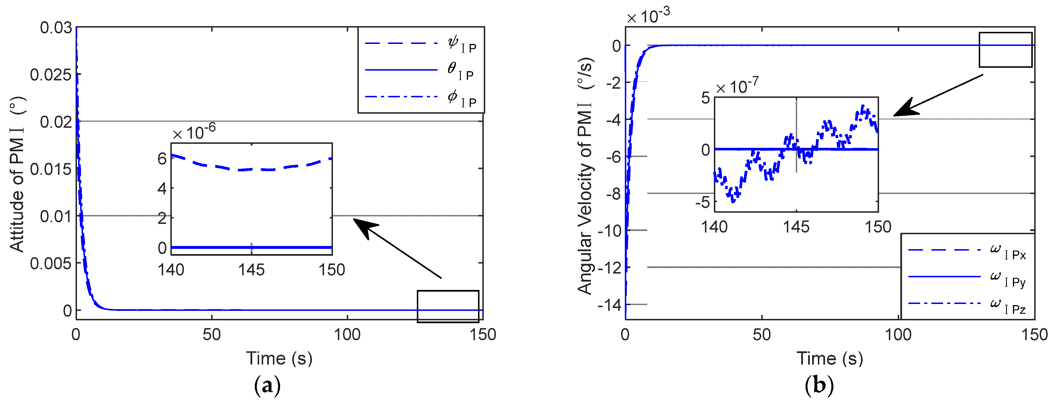
Figure 7 illustrate the attitude curve and angular velocity curve of PM I, respectively. Similarly, Figure 8 shows the attitude curve and angular velocity curve of PM II.
As is shown in Figure 5, the norms of the three components of the relative position error are kept within 2 mm, which indicates that the control system designed in this paper can well satisfy the noncontact actuator’s working range requirement ( 5 mm ) [26]. Based on the simulation results in Figure 6, Figure 7 and Figure 8 the pointing performances of SM, PM I and PM II are summarized in Table 10, Table 11 and Table 12 respectively.
According to Table 10, both the pointing accuracy and pointing stability of SM are of an order of −3.
As is presented in Table 11, the pointing accuracy of PM I reaches an order of −6, while the pointing stability of PM I is of an order of −7.
Table 12 demonstrates that the pointing accuracy of PM II is of an order of −5, while the pointing stability of PM II reaches an order of −7.
Comparing the above results between the support module and payload modules, both PM I and PM II achieve a pointing performance increase of more than two orders of magnitude. Specifically, as for the pointing accuracy, PM I and PM II are three orders and two orders lower than their counterpart, SM. As regards the pointing stability, both payloads are four orders lower than SM.
Extensive experimental tests have been performed to validate the proposed novel DFP system in comparison with traditional spacecraft. Table 13 summarizes the pointing performance comparison between the proposed novel DFP system and a traditional spacecraft system.
Modern space missions put forward arcsecond-level pointing and stability requirements for satellite platforms. The attitude of the satellite platform in the mission of the NESS (Near-Earth Space Surveillance) is required to be stabilized to ~10 arcsec [27]. The stability requirement of the satellite platform in the PICARD scientific mission is over 5 arcsec/s [28]. For the Herschel Space Observatory, it is required that the APE (absolute pointing error) in star pointing is 3.7 arcsec and the RPE (pointing drift error) requirement (for a period of 60 s) is 0.30 arcsec [29]. From the above-mentioned modern space missions, it is clear that arcsec-level pointing performance and arcsec/s-level stability performance are greatly needed [30]. According to the pointing performance comparison in Table 13, the pointing and stability performance of the proposed novel DFP system meet the arcsec-level and arcsec/s-level requirements and outperform its counterpart, the traditional spacecraft system.
The proposed novel DFP system provides excellent performance that meets high-precision pointing requirements. In addition, the pointing performances of both payloads outperform support module, thus proving to be a promising solution for collaborative observation missions.

8. Conclusions

This paper proposes a novel DFP system for collaborative observation. In comparison with a conventional DFP system, the support module carries more than one payload modules via the noncontact actuator. The six-degrees-of-freedom multibody rigid–flexible dynamics of the novel DFP system are derived via Newtonian mechanics. The dynamics model, considering the solar panels and umbilical as the flexible part, can precisely depict the motion of the DFP system.
Simulation studies for a collaborative observation mission were conducted to test the performance of the novel DFP system. The simulation results indicate that the proposed novel DFP system can not only deal with a collaborative observation mission but also achieve high pointing performance.
Although the number of payloads in the proposed DFP system is two, more payloads can be introduced via the noncontact actuator. More payloads incorporated into the DFP system means more complex dynamics of the system. Thus, considerable attention in future work should be paid to a coupling effect analysis between different payloads.

Author Contributions

Conceptualization, Y.D. and X.C.; methodology, Y.D.; validation, Y.D. and X.C.; formal analysis, Y.D. and J.Z.; investigation, X.C. and J.Z.; resources, Y.D.; data curation, X.C.; writing—original draft preparation, Y.D., J.Z. and Y.Y.; writing—review and editing, J.Z., Y.Y. and Q.H.; visualization, Y.Y. and Q.H.; supervision, Y.D.; project administration, X.C.; funding acquisition, J.Z. All authors have read and agreed to the published version of the manuscript.

Funding

This research was supported in part by Fujian Provincial Department of Science and Technology under the Natural Science Foundation of Fujian Province, China (grant no. 2022J05286); in part by Xiamen Municipal Bureau of Science and Technology under the Natural Science Foundation of Xiamen, China (grant no. 3502Z20227072); in part by Fujian Provincial Department of Education under the Youth Foundation of Fujian Educational Committee, Fujian, China (grant no. JAT210343); and in part by Xiamen University of Technology under the Startup Fund for Distinguished Scholars, Xiamen University of Technology of China (grant no. YKJ22019R).

Data Availability Statement

Data are available on request due to restrictions, e.g., privacy or ethical.

Conflicts of Interest

The authors declare no conflict of interest.

References

  1. Yang, J.; Zhang, Z.; Jiang, F.; Li, J. Low-Energy Transfer Design of Heliocentric Formation Using Lunar Swingby on the Exampe of LISA. Aerospace 2022, 10, 18. [Google Scholar] [CrossRef]
  2. Liang, J.; Liu, L.; Tang, S. Sensitivity Modeling and Enhancement for Space-Based Gravitational Wave Detector with Optical Atomic Clocks under Solar Radiation Disturbance. Microgravity Sci. Technol. 2021, 33, 1–15. [Google Scholar] [CrossRef]
  3. Yamamoto, K.; Vorndamme, C.; Hartwig, O. Experimental verification of intersatellite clock synchronization at LISA performance levels. Phys. Rev. D 2022, 105, 042009. [Google Scholar] [CrossRef]
  4. Luo, Z.; Wang, Y.; Wu, Y. The Taiji program: A concise overview. Prog. Theor. Exp. Phys. 2021, 2021, 05A108. [Google Scholar] [CrossRef]
  5. He, Z.; Feng, X.; Zhu, Y.; Yu, Z.; Li, Z.; Zhang, Y.; Wang, P.; Zhao, L. Progress of Stewart Vibration Platform in Aerospace Micro—Vibration Control. Aerospace 2022, 9, 324. [Google Scholar] [CrossRef]
  6. Cao, D.; Bai, K.; Ding, H. Advances in dynamics and vibration control of large-scale flexible spacecraft. Chin. J. Theor. Appl. Mech. 2019, 51, 1–13. [Google Scholar]
  7. Ji, H.; Zhou, C.; Fan, J.; Dai, H.; Jiang, W.; Gong, Y.; Xu, C.; Wang, B.; Zhou, W. Angular Displacement Control for Timoshenko Beam by Optimized Traveling Wave Method. Aerospace 2022, 9, 259. [Google Scholar] [CrossRef]
  8. Zhu, C.; Liu, X.; Zhao, F. Research on Semi-active Control of Low Frequency Vibration of SAR Satellite under Fast Maneuvering Conditions. In Proceedings of the 2021 2nd China International SAR Symposium (CISS), Shanghai, China, 3–5 November 2021; pp. 1–6. [Google Scholar]
  9. Azimi, M.; Sharifi, G. A hybrid control scheme for attitude and vibration suppression of a flexible spacecraft using energy-based actuators switching mechanism. Aerosp. Sci. Technol. 2018, 82, 140–148. [Google Scholar] [CrossRef]
  10. Zhang, C.; Ma, G.; Sun, Y. Prescribed performance adaptive attitude tracking control for flexible spacecraft with active vibration suppression. Nonlinear Dyn. 2019, 96, 1909–1926. [Google Scholar] [CrossRef]
  11. Xu, S.; Cui, N.; Fan, Y. Active vibration suppression of flexible spacecraft during attitude maneuver with actuator dynamics. IEEE Access 2018, 6, 35327–35337. [Google Scholar] [CrossRef]
  12. He, T.; Wu, Z. Extended disturbance observer with measurement noise reduction for spacecraft attitude stabilization. IEEE Access 2019, 7, 66137–66147. [Google Scholar] [CrossRef]
  13. Dou, L.; Du, M.; Zhang, X. Fuzzy disturbance observer-based sliding mode control for liquid-filled spacecraft with flexible structure under control saturation. IEEE Access 2019, 7, 149810–149819. [Google Scholar] [CrossRef]
  14. Pedreiro, N. Spacecraft architecture for disturbance-free payload. J. Guid. Control Dyn. 2003, 26, 794–804. [Google Scholar] [CrossRef]
  15. Gonzales, M.; Pedreiro, N.; Brookes, K. Unprecedented vibration isolation demonstration using the disturbance-free payload concept. In Proceedings of the AIAA Guidance, Navigation, and Control Conference and Exhibit, Providence, RI, USA, 16–19 August 2004; p. 5247. [Google Scholar]
  16. Zhou, J.; Wang, Z.; Li, W. Modeling and pointing performance analysis of disturbance-free-payload system with flexible umbilical connection. IEEE Access 2019, 7, 109585–109596. [Google Scholar] [CrossRef]
  17. Yang, H.; Liu, L.; Liu, Y. Modeling and micro-vibration control of flexible cable for disturbance-free payload spacecraft. Microgravity Sci. Technol. 2021, 33, 1–16. [Google Scholar] [CrossRef]
  18. Yang, H.; Liu, L.; Yun, H. Modeling and collision avoidance control for the Disturbance-Free Payload spacecraft. Acta Astronaut. 2019, 164, 415–424. [Google Scholar] [CrossRef]
  19. Li, G.; Zhang, H.; Xie, J. Dataset of Multi-satellite Synchronous and Collaborative Observation in Zhangye 2013. J. Glob. Chang. Data Discov. 2017, 1, 216–224. [Google Scholar]
  20. Krauß, T.; d’Angelo, P.; Wendt, L. Cross-track satellite stereo for 3D modelling of urban areas. Eur. J. Remote Sens. 2019, 52, 89–98. [Google Scholar] [CrossRef]
  21. Jove-Casurellas, R.; Araguz, C.; Via, P.; Solanellas, A.; Amézaga, A.; Vidal, D.; Muñoz, J.F.; Marí, M.; Olivé, R.; Saez, A.; et al. 3Cat-1 project: A multi-payload CubeSat for scientific experiments and technology demonstrators. Eur. J. Remote Sens. 2017, 50, 125–136. [Google Scholar] [CrossRef]
  22. Bevacqua, T.; Chapel, J.; Stancliffe, D. In-Flight Line-of-Sight Pointing Performance for the GOES-16 and GOES-17 Spacecraft. In Proceedings of the Annual American Astronautical Society Guidance, Navigation and Control Conference (AAS GN & C 2019) (AAS 19-133), Breckenridge, CO, USA, 31 January–6 February 2019. [Google Scholar]
  23. Minelli, G.; Ricco, A.; Beasley, C. O/OREOS nanosatellite: A multi-payload technology demonstration. In Proceedings of the Small Satellite Conference, Logan, UT, USA, 9–12 August 2010. [Google Scholar]
  24. Sui, Q.; Yuan, J.; Jiang, Y. Attitude perturbation of spin-stabilized satellite caused by gravity gradient moment. J. Spacecr. TTC Technol. 2011, 30, 1–5. [Google Scholar]
  25. Cai, L.; Zhang, G.; Hong, T.; Li, W.; Lin, H.; Sun, Z. Analysis of the law of LEO satellite spin motion under the influence of gravity gradient torque. Chin. Space Sci. Technol. 2021, 41, 17–24. [Google Scholar]
  26. Trankle, T.; Pedreiro, N.; Andersen, G. Disturbance free payload flight system analysis and simulation methods. In Proceedings of the AIAA Guidance, Navigation, and Control Conference and Exhibit, Providence, RI, USA, 16–19 August 2004; p. 5875. [Google Scholar]
  27. Carroll, K.A.; Grocott, S. Arc-second attitude control for the NESS asteroid/satellite tracking microsat. Spacecr. Guid. Navig. Control. Syst. 2003, 516, 445. [Google Scholar]
  28. Samson, P. High pointing accuracy with the PICARD micro satellite. IFAC Proc. Vol. 2007, 40, 295–300. [Google Scholar] [CrossRef]
  29. Sánchez-Portal, M.; Marston, A.; Altieri, B.; Aussel, H.; Feuchtgruber, H.; Klaas, U.; Linz, H.; Lutz, H.; Merín, B.; Müller, T.; et al. The pointing system of the Herschel space observatory: Description, Calibration, Performance and improvements. Exp. Astron. 2014, 37, 453–479. [Google Scholar] [CrossRef]
  30. Li, A.; Sun, J.; Liu, L. Design principle of performance testing device for laser beam microradian pointing and tracking in intersatellite laser communications. Acta Opt. Sin. 2006, 26, 975. [Google Scholar] [CrossRef]
Figure 1. Configuration of a conventional DFP system.
Aerospace 10 00527 g001
Figure 2. Configuration of the novel DFP system.
Aerospace 10 00527 g002
Figure 3. Vector description of the DFP system.
Aerospace 10 00527 g003
Figure 4. DFP control architecture.
Aerospace 10 00527 g004
Figure 5. Relative position error curve: (a) PM I and (b) PM II.
Aerospace 10 00527 g005
Figure 6. Attitude and angular velocity curve of SM: (a) attitude curve and (b) angular velocity curve.
Aerospace 10 00527 g006
Figure 7. Attitude and angular velocity curve of PM I: (a) attitude curve and (b) angular velocity curve.
Aerospace 10 00527 g007
Figure 8. Attitude and angular velocity curve of PM II: (a) attitude curve and (b) angular velocity curve.
Aerospace 10 00527 g008
Table 1. Definitions of the vectors.
VectorDefinition
r i Position vector of Bead Ii
r i Position vector of Bead IIi
r P Position vector of Payload Module I
r P Position vector of Payload Module II
r S Position vector of Support Module
d S Position vector of junction point between Umbilical I and SM
d S Position vector of junction point between Umbilical II and SM
d P Position vector of junction point between Umbilical I and PM I
d P Position vector of junction point between Umbilical I and PM II
ρ r Relative position vector between SM and PM I
ρ r Relative position vector between SM and PM II
ρ S i Relative position vector between Bead Ii and SM
ρ S i Relative position vector between Bead IIi and SM
ρ i Relative position between Bead Ii and Bead Ii-1
ρ i Relative position between Bead IIi and Bead IIi-1
Table 2. Forces and moments acting on PM I.
Force/MomentDefinition
F Pg Earth’s gravity
F Pd Disturbing force
T Pd Disturbing moment
F Pu Umbilical force
T Pu Umbilical moment
F Pc Control force applied by noncontact actuator
T Pc Control torque applied by noncontact actuator
Table 3. Forces and moments acting on PM II.
Force/MomentDefinition
F Pg Earth’s gravity
F Pd Disturbing force
T Pd Disturbing moment
F Pu Umbilical force
T Pu Umbilical moment
F Pc Control force applied by noncontact actuator
T Pc Control torque applied by noncontact actuator
Table 4. Forces and moments acting on SM.
Force/MomentDefinition
F Sg Earth’s gravity
F Sd Disturbing force
T Sd Disturbing moment
F S u Umbilical force applied by Umbilical I
T Su Umbilical moment applied by Umbilical I
F S u Umbilical force applied by Umbilical II
T S u Umbilical moment applied by Umbilical II
F S c Control force applied by external actuators
T S c Control torque applied by external actuators
F Sin t Interaction force applied by Noncontact Actuator I
T Sin t Interaction moment applied by Noncontact Actuator I
F Sin t Interaction force applied by Noncontact Actuator II
T Sin t Interaction moment applied by Noncontact Actuator II
Table 5. Forces acting on Bead Ii.
ForceDefinition
F i g Earth’s gravity
F B i Spring force on Bead Ii applied by adjacent beads, i.e., Bead Ii − 1 and Bead Ii + 1
Table 6. Forces acting on Bead IIi.
ForceDefinition
F i g Earth’s gravity
F B i Spring force on Bead IIi applied by adjacent beads, i.e., Bead IIi − 1 and Bead IIi + 1
Table 7. Definitions of control parameters.
ParameterDefinition
K PP Proportional gain for PM I attitude control loop
K PD Derivative gain for PM I attitude control loop
K PP Proportional gain for PM II attitude control loop
K PD Derivative gain for PM II attitude control loop
K RTP Proportional gain for relative position control loop between PM I and SM
K RTD Derivative gain for relative position control loop between PM I and SM
K RTP Proportional gain for relative position control loop between PM II and SM
K RTD Derivative gain for relative position control loop between PM II and SM
K RAP Proportional gain for relative attitude control loop between PM I and SM
K RAD Derivative gain for relative attitude control loop between PM I and SM
q P v 0 , q P v Vector part of desired quaternion and real-time quaternion of PM I
ω P 0 , ω P Desired and real-time angular velocity of PM I
q P v 0 , q P v Vector part of desired quaternion and real-time quaternion of PM II
ω P 0 , ω P Desired and real-time angular velocity of PM II
ρ r 0 , ρ ˙ r 0 Desired relative position vector and desired relative velocity vector SM and PM I
ρ r 0 , ρ ˙ r 0 Desired relative position vector and desired relative velocity vector SM and PM II
q R v 0 , q R v Vector part of desired and real-time relative attitude quaternion between SM and PM I
ω R 0 , ω R Desired and real-time relative angular velocity between SM and PM I
Table 8. Simulation conditions.
VariableVariable NameValue
M S kg Mass of SM 2334
I S kg m 2 Moment of inertia of SM diag 4552 4884 6992
M Ι P kg Mass of PM I 100
M P kg Mass of PM II 100
I P kg m 2 Moment of inertia of PM I diag 86 85 113
I P kg m 2 Moment of inertia of PM II diag 86 85 113
a km Semimajor axis of Nominal Orbit 6598
e Eccentricity of Nominal Orbit 0
I ° Inclination of Nominal Orbit 0
Ω orbit ° Longitude of Ascending Node 0
ω ° Argument of Periapsis 0
ψ ° True anomaly at Epoch 0
l u m Length of Umbilical I 1
l u m Length of Umbilical II 1
k u N / m Stiffness of Umbilical I 40
k u N / m Stiffness of Umbilical II 40
M u kg Mass of Umbilical I 1
M u kg Mass of Umbilical II 1
N Bead number10
d S Position vector of junction point between Umbilical I and SM 0 . 3 0 . 4 0
d S Position vector of junction point between Umbilical II and SM 0 . 3 0 . 4 0
d P Position vector of junction point between Umbilical I and PM I 0 . 5 0 . 5 0
d P Position vector of junction point between Umbilical I and PM II 0 . 5 0 . 5 0
ζ Modal damping ratio of Solar Panels diag 0 . 009 0 . 0138 0 . 02083 0 . 04
Ω Hz Fundamental frequencies of Solar Panels diag 0 . 15853 0 . 44764 0 . 86703 0 . 96188
B t Translational coupling matrix of Solar Panels 0.0706 7.2756 1.0032 0.0134 0.2283 0.1923 0.0682 1.6051 6.9815 0.0017 0.0936 3.8853
B r Rotational coupling matrix of Solar Panels 44.7546 0.2369 0.2179 9.6937 0.2404 12.1033 5.9076 0.013 0.4144 45.8615 5.6713 0.0151
Table 9. Control system parameters.
ParameterParameter NameValue
K PP Proportional gain for PM I attitude control loop 3 × 10 4 × diag 1 1 1
K PD Derivative gain for PM I attitude control loop 3 × 10 4 × diag 1 1 1
K PP Proportional gain for PM II attitude control loop 3 × 10 4 × diag 1 1 1
K PD Derivative gain for PM II attitude control loop 3 × 10 4 × diag 1 1 1
K RTP Proportional gain for relative position control loop between PM I and SM 10 4 × diag 1 1 1
K RTD Derivative gain for relative position control loop between PM I and SM 10 3 × diag 1 1 1
K RTP Proportional gain for relative position control loop between PM II and SM 10 4 × diag 1 1 1
K RTD Derivative gain for relative position control loop between PM II and SM 10 3 × diag 1 1 1
K RAP Proportional gain for relative attitude control loop between PM I and SM 5 × 10 2 × diag 1 1 1
K RAD Derivative gain for relative attitude control loop between PM I and SM 5 × 10 2 × diag 1 1 1
q P v 0 Vector part of desired quaternion of PM I 0 0 0
ω P 0 ° / s Desired angular velocity of PM I 0 0 0
q P v 0 Vector part of desired quaternion of PM II 0 0 0
ω P 0 ° / s Desired angular velocity of PM II 0 0 0
ρ r 0 m , ρ ˙ r 0 m / s Desired relative position vector and desired relative velocity vector SM and PM I 1.8 0.1 0.0004 , 0 0 0
ρ r 0 m , ρ ˙ r 0 m / s Desired relative position vector and desired relative velocity vector SM and PM II 1.8 0.9 0.0008 , 0 0 0
q R v 0 Vector part of desired relative attitude quaternion between SM and PM I 0 0 0
ω R 0 ° / s Desired relative angular velocity between SM and PM I 0 0 0
Table 10. Pointing performance of SM.
Pointing PerformanceSM
Pointing accuracy (°) 2.576 × 10 3 / s
Pointing stability (°/s) 1.824 × 10 3 / s 2
Table 11. Pointing performance of PM I.
Pointing PerformancePM I
Pointing accuracy (°) 6.2 × 10 6
Pointing stability (°/s) 5 × 10 7
Table 12. Pointing performance of PM II.
Pointing PerformancePM II
Pointing accuracy (°) 2.3 × 10 5
Pointing stability (°/s) 5 × 10 7
Table 13. Pointing performance comparison between the proposed novel DFP system and a traditional spacecraft system.
Pointing PerformanceProposed Novel DFP SystemTraditional Spacecraft System
PM IPM II
Pointing accuracy (arcsec) 0.02 0.0828 9
Pointing stability (arcsec/s) 0.0018 0.0018 6.5
Disclaimer/Publisher’s Note: The statements, opinions and data contained in all publications are solely those of the individual author(s) and contributor(s) and not of MDPI and/or the editor(s). MDPI and/or the editor(s) disclaim responsibility for any injury to people or property resulting from any ideas, methods, instructions or products referred to in the content.

