
Internal Characteristics of Air-Supplied Plasma Synthetic Jet Actuator

Abstract
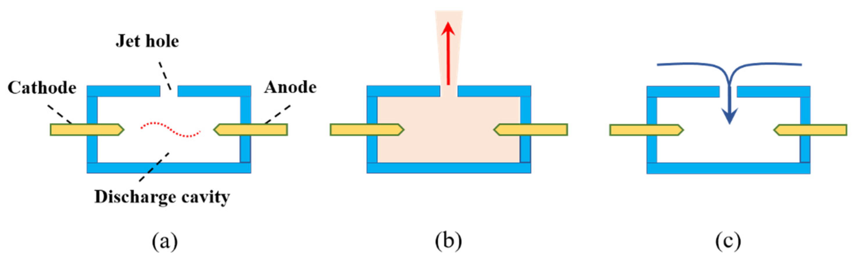
:1. Introduction
2. Experimental Setup
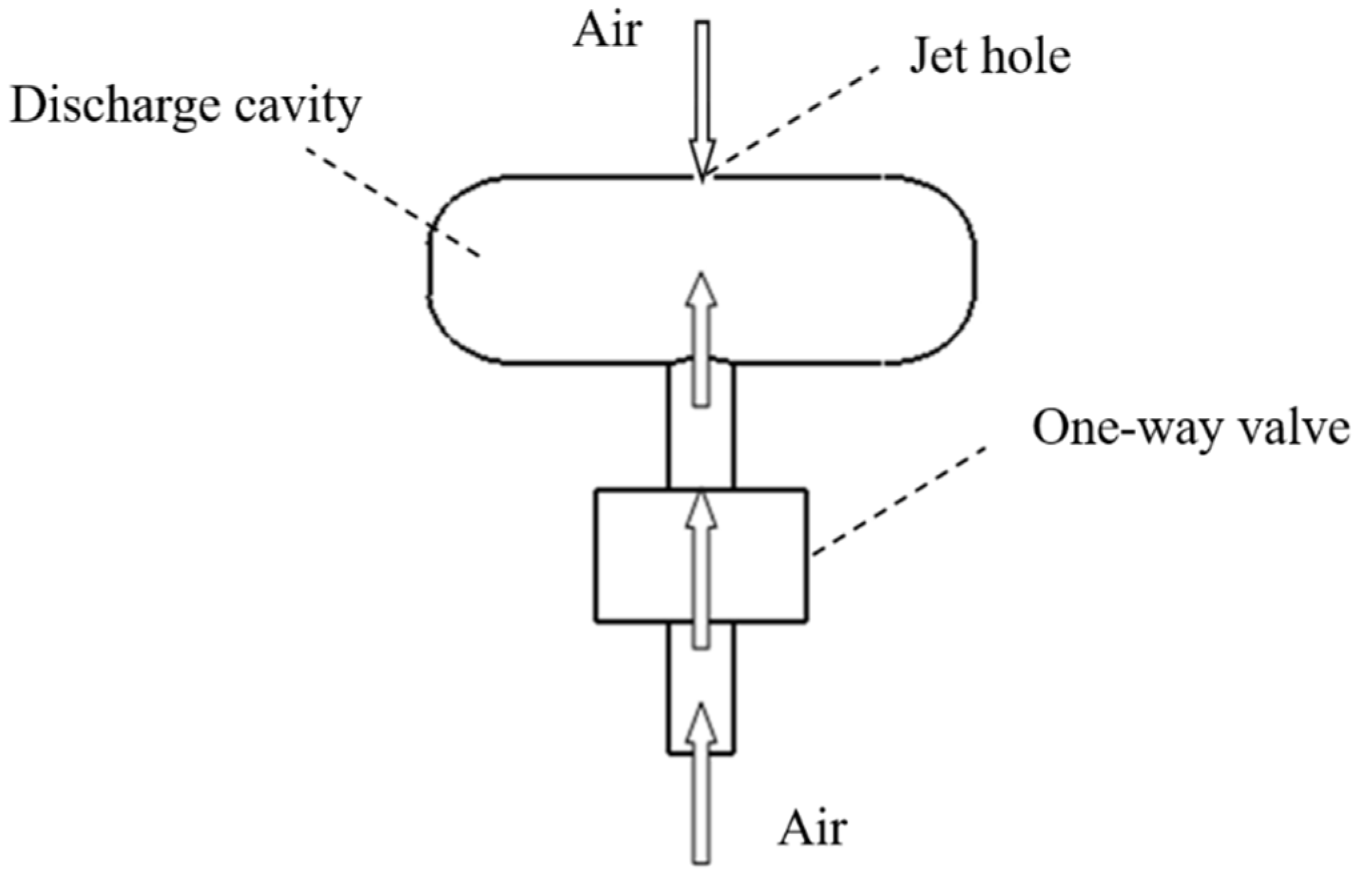
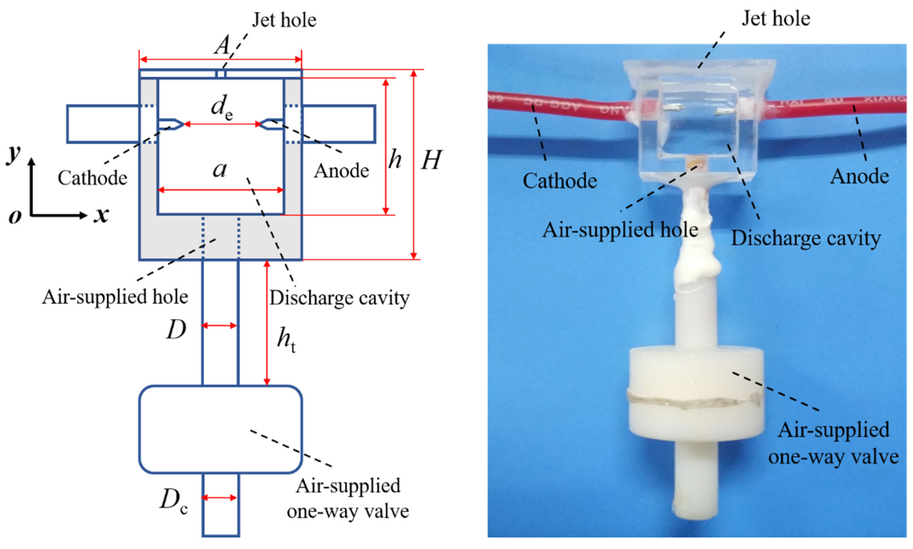
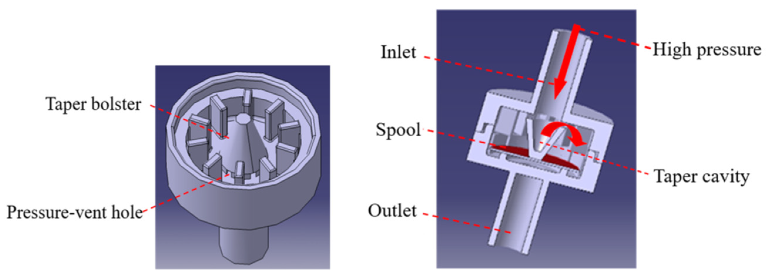
2.1. Quartz Gas-Supplemented Plasma Synthetic Jet Actuator
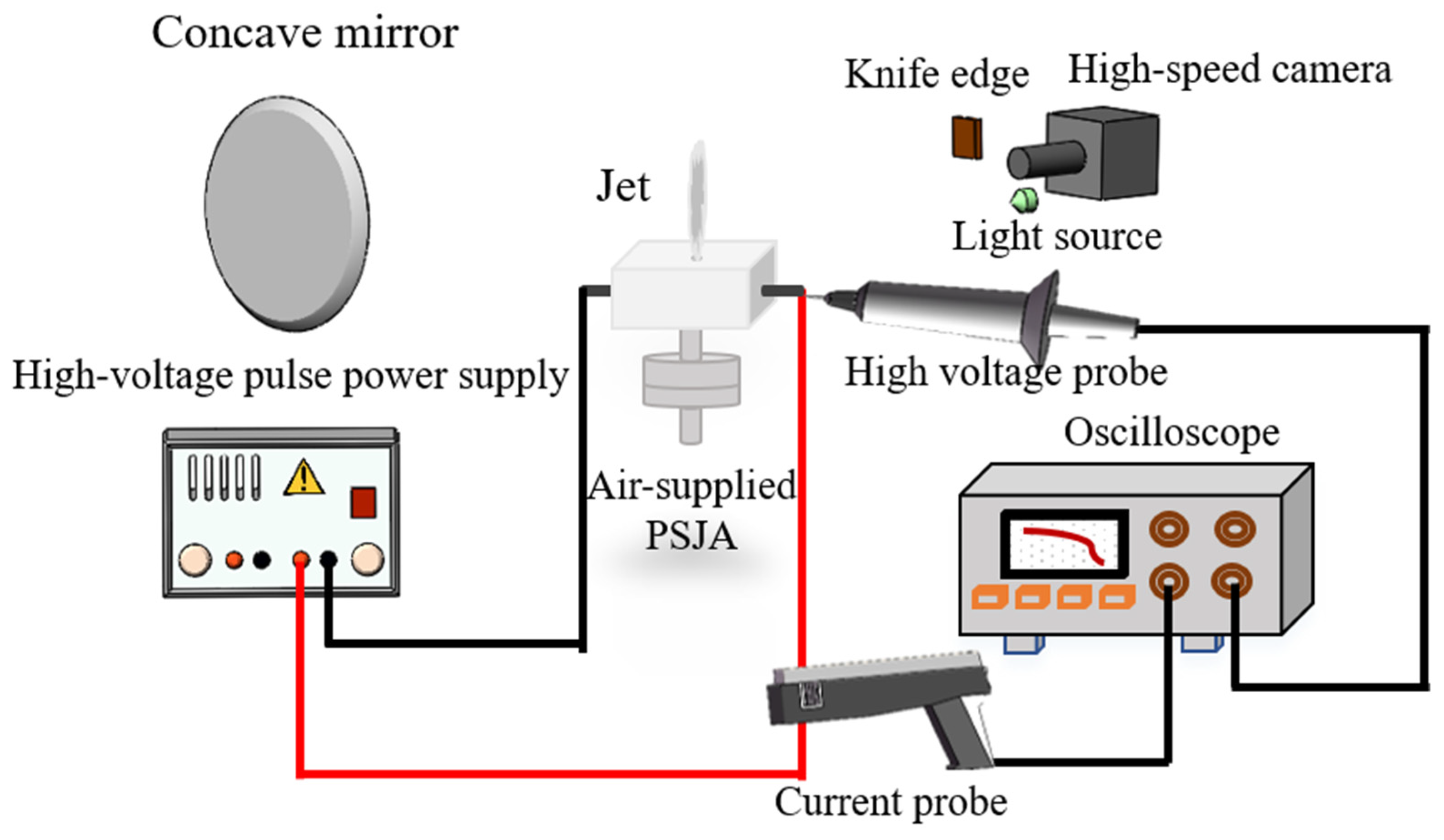
2.2. Power Source and Discharge Characteristic Measurement Setup
2.3. High-Speed Schlieren Measurement System
3. Characteristics Measurement Experiment of Air Supplement PSJA
3.1. Ineffective Frequency Band
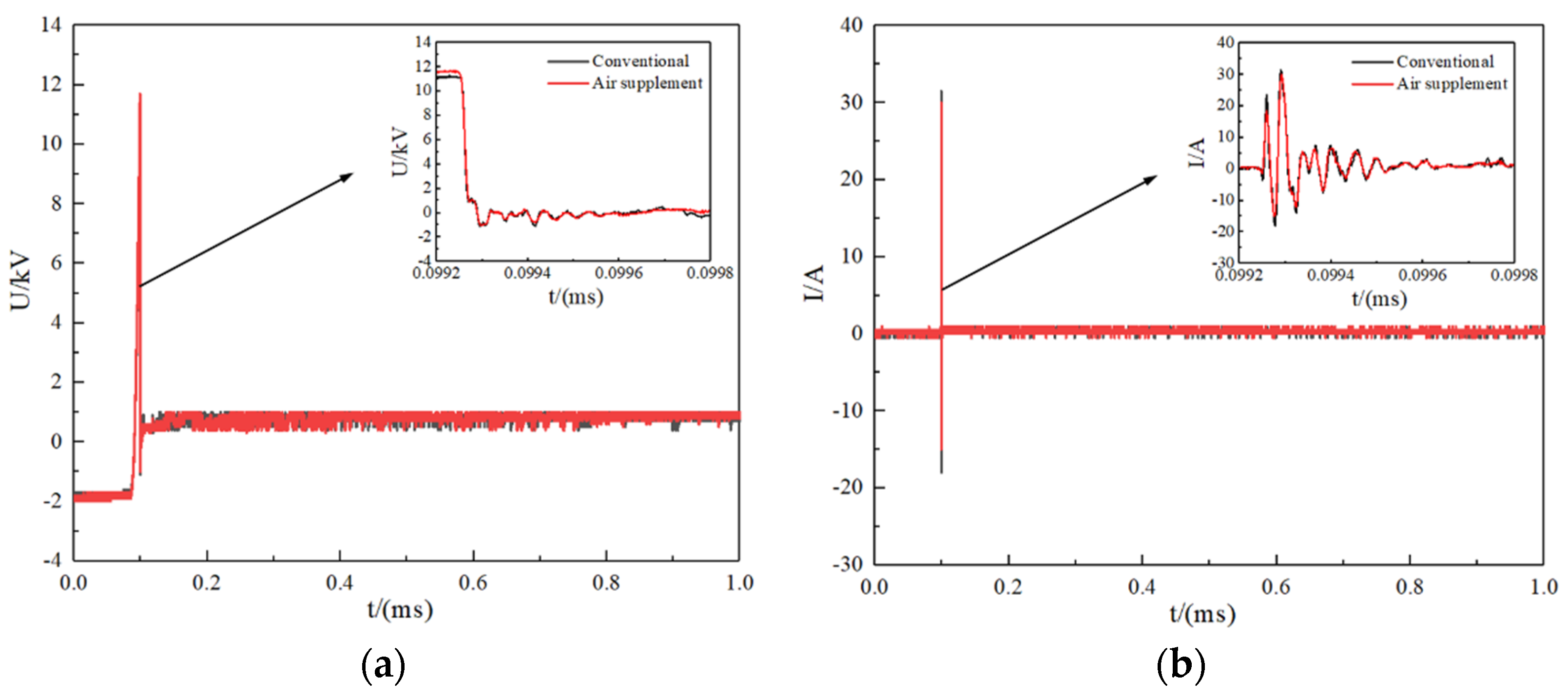
3.1.1. Discharge Characteristic Measurement
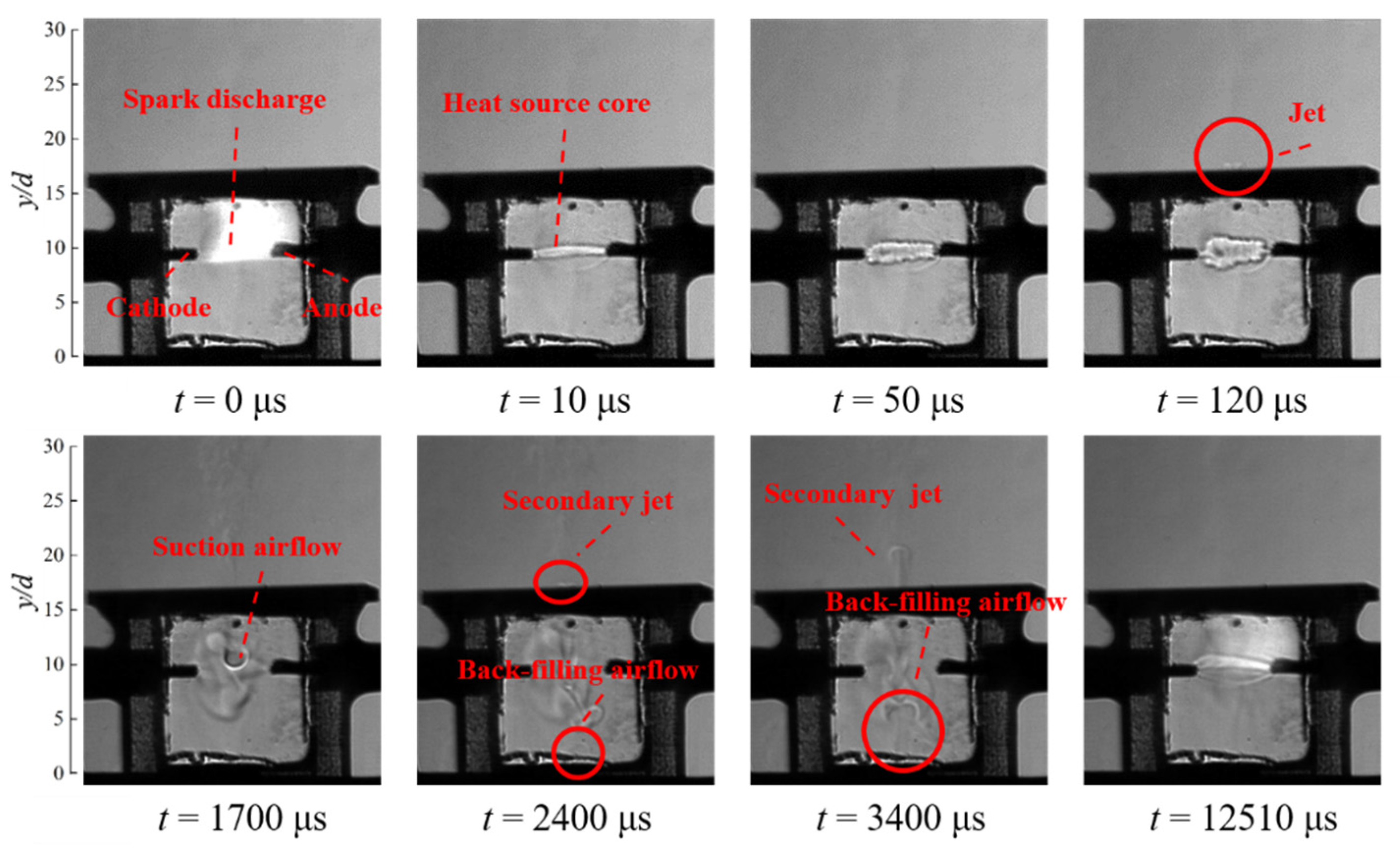
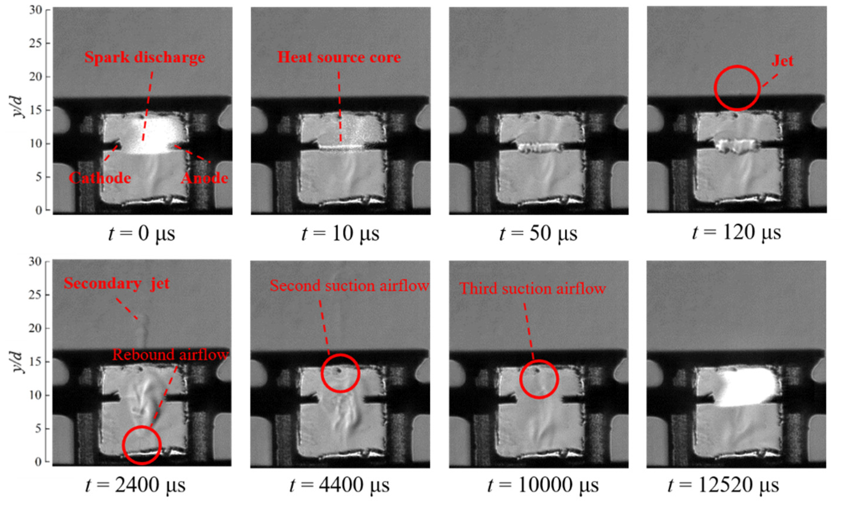
3.1.2. Flow Field Evolution in Cavity
- 1.
- Air supplement excitation state
- 2.
- Conventional excitation state
- 3.
- Comparative analysis
3.2. Effective Frequency Band
3.2.1. Discharge Characteristic Measurement
3.2.2. Flow Field Evolution in Cavity
- 1.
- Air supplement excitation state
- 2.
- Conventional excitation state
- 3.
- Comparative analysis
4. Inner Flow Model of Air-Supplied Plasma Synthetic Jet Actuator
4.1. Invalid Working Frequency Band
4.2. Effective Working Frequency Band
5. Conclusions
- (1)
- The peak current and voltage of the air-replenishing actuator in the ineffective frequency band did not increase significantly during spark discharge, the discharge energy remained unchanged within a single cycle, and the efflux performance did not improve.
- (2)
- The air supplement excitation state actuator could recover the air pressure state in the cavity more rapidly. The phenomenon of multiple jet hole replenishments in the conventional excitation state was avoided.
- (3)
- In the effective frequency band, the peak voltage and current during spark discharge were improved to a certain extent, and the discharge energy within a single cycle increased by 18.9%.
- (4)
- In the effective frequency band, the suction airflow velocity increased exponentially in the inspiratory recovery stage. Only one suction was required to complete the recovery process, and inspiratory recovery enhanced the uniformity of the gas density distribution in the cavity.
- (5)
- The air replenishment effect of the one-way valve alleviated the influence of the core sag of the heat source on its expansion, which increased both the negative pressure required for jet generation and jet energy generation.
- (6)
- For future work, a transparent air replenishment one-way valve can be developed to study the flow state inside the one-way valve and improve its structure of the one-way valve.
Author Contributions
Funding
Data Availability Statement
Acknowledgments
Conflicts of Interest
References
- Ikhlaq, M.; Yasir, M.; Demiroğlu, M.; Arik, M. Synthetic Jet Cooling Technology for Electronics Thermal Management—A Critical Review. IEEE Trans. Compon. Packag. Manuf. Technol. 2021, 11, 1156–1170. [Google Scholar] [CrossRef]
- Grossman, K.R.; Cybyk, B.Z.; VanWie, D.M. Sparkjet actuators for flow control. In Proceedings of the 41st AIAA Aerospace Sciences Meeting and Exhibit, Reno, NV, USA, 6–9 January 2003; pp. 1–9. [Google Scholar]
- Cybyk, B.Z.; Simon, D.H.; Land, H.B., III. Experimental characterization of a supersonic flow control actuator. In Proceedings of the 44th AIAA Aerospace Sciences Meeting and Exhibit, Reno, NV, USA, 9–12 January 2006; pp. 1–12. [Google Scholar]
- Sarah, J.H.; Bruce, L.H.; Cybyk, B.Z.; Ko, H.; Katz, J. Characterization of a high-speed flow control actuator using digital speckle tomography and PIV. In Proceedings of the 4th Flow Control Conference, Seattle, WA, USA, 23–26 June 2008; pp. 1–12. [Google Scholar]
- Popkin, S.H.; Cybyk, B.Z.; Land, H.B., III; Foster, C.; Emerick, T.; Alvi, F. Recent performance-based advances in Sparkjet actuator design for supersonic flow applications. In Proceedings of the 51st AIAA Aerospace Sciences Meeting Including the New Horizons Forum and Aerospace Exposition, Grapevine, TX, USA, 7–10 January 2013; pp. 1–11. [Google Scholar]
- Popkin, S.H.; Cybyk, B.Z.; Foster, C.H.; Alvi, F.S. Experimental estimation of Sparkjet efficiency. AIAA J. 2016, 54, 1831–1845. [Google Scholar] [CrossRef]
- Zong, H.H.; Pelt, V.T.; Kotsonis, M. Airfoil flow separation control with plasma synthetic jets at moderate Reynolds number. Exp. Fluids 2018, 59, 169. [Google Scholar] [CrossRef] [Green Version]
- Sun, J.; Niu, Z.G.; Liu, R.B.; Liu, Q. The wind tunnel test of the active flow control on the flying wing model based on the plasma synthetic jet. J. Exp. Fluid Mech. 2019, 33, 81–88. [Google Scholar]
- Chedevergne, F.; Léon, O.; Bodoc, V.; Caruana, D. Experimental and numerical response of a high-Reynolds-number M = 0.6 jet to a plasma synthetic jet actuator. Int. J. Heat Fluid Flow 2015, 56, 1–15. [Google Scholar] [CrossRef]
- Emerick, T.; Ali, M.Y.; Foster, C.; Alvi, F.S.; Popkin, S. SparkJet characterizations in quiescent and supersonic flowfields. Exp. Fluids 2014, 55, 1858. [Google Scholar] [CrossRef]
- Zhou, Y.; Xia, Z.X.; Luo, Z.B.; Wang, L.; Deng, X.; Zhang, Q.; Yang, S. Characterization of three-electrode sparkjet actuator for hypersonic flow control. AIAA J. 2018, 57, 879–885. [Google Scholar] [CrossRef]
- Wang, H.Y.; Li, J.; Jin, D.; Tang, M.; Wu, Y.; Xiao, L. High-frequency counter-flow plasma synthetic jet actuator and its application in suppression of supersonic flow separation. Acta Astronaut. 2018, 142, 45–56. [Google Scholar] [CrossRef]
- Tang, M.X.; Wu, Y.; Wang, H.Y.; Shanguang, G.; Zhengzhong, S.; Jiaming, S. Characterization of transverse plasma jet and its effects on ramp induced separation. Exp. Therm. Fluid Sci. 2018, 99, 584–594. [Google Scholar]
- Gu, R.Y.; Shan, Y.; Zhang, J.Z. Numerical study on transport aircraft after-body flow separation control by spark jet. J. Aerosp. Power 2018, 33, 1855–1863. [Google Scholar]
- Liu, R.B.; Wei, W.T.; Li, F.; Lin, Q. Working mechanism of air-supplemented plasma synthetic jet actuator. Acta Aeronaut. Astronaut. Sin. 2022, 43, 125854-1–125854-15. [Google Scholar]
- Wang, L.; Luo, Z.B.; Xia, Z.X.; Liu, B.; Deng, X. Review of actuators for high speed active flow control. Sci. China Tech. Sci. 2012, 55, 2225–2240. [Google Scholar] [CrossRef]
- Zhou, Y.; Luo, Z.B.; Wang, L.; Xia, Z.X.; Gao, T.X.; Xie, W.; Deng, X.; Peng, W.Q.; Cheng, P. Plasma synthetic jet actuator for flow control: Review. Acta Aeronaut. Astronaut. Sin. 2022, 43, 98–140. [Google Scholar]
- Zhou, Y.; Xia, Z.X.; Luo, Z.B.; Wang, L.; Deng, X. A novel ram-air plasma synthetic jet actuator for near space high-speed flow control. Acta Astronaut. 2017, 133, 95–102. [Google Scholar] [CrossRef]
- Li, J.F.; Zhang, X.B. Active flow control for supersonic aircraft: A novel hybrid synthetic jet actuator. Sens. Actuators A Phys. 2020, 302, 111770. [Google Scholar] [CrossRef]
- Emerick, T.M.; Ali, M.Y.; Foster, C.H.; Alvi, F.; Haack Popkin, S.; Cybyk, B. Sparkjet actuator Characterization in supersonic crossflow. In Proceedings of the 6th AIAA Flow Control Conference, New Orleans, LA, USA, 25–28 June 2012; pp. 1–10. [Google Scholar]
- Zhou, Y.; Xia, Z.X.; Luo, Z.B.; Zhou, Y.; Liu, Q.; Peng, W. Characterization of plasma synthetic jet actuator with cavity pressurization. J. Natl. Univ. Def. Technol. 2019, 41, 12–18. [Google Scholar]
- Zong, H.H.; Liang, H.; Song, G.Z. Self-Air-Supplementing Type Double-Cavity Plasma Synthetic Jet Actuator. CN 113993266 A, 28 January 2022. [Google Scholar]
- Zheng, B.R.; Zhang, Q.; Zhao, T.F.; Song, G.; Chen, Q. Experimental and numerical investigation of a self-supplementing dual-cavity plasma synthetic jet actuator. Plasma Sci. Technol. 2023, 25, 025503. [Google Scholar] [CrossRef]
- Liu, R.B.; Wang, M.M.; Hao, M.; Lin, Q.; Wang, X.G. Experimental research on air supplementing type plasma synthetic jet generator. Acta Aeronaut. Astronaut. Sin. 2016, 37, 1713–1721. [Google Scholar]
- Dong, H.; Geng, X.; Shi, Z.W.; Cheng, K.; Cui, Y.D.; Khoo, B.C. On evolution of flow structures induced by nanosecond pulse discharge inside a plasma synthetic jet actuator. Jpn. J. Appl. Phys. 2019, 58, 028002-1–028002-5. [Google Scholar] [CrossRef]
- Li, F. Study on Improving the Performance and Working Mechanism of Plasma Synthetic Jet Actuator by Check Valve; Xiamen University: Xiamen, China, 2020. [Google Scholar]
- Liu, R.B.; Li, F.; Wei, W.T.; Chen, G.T.; Lin, Q. One-Way Valve and Plasma Synthetic Jet Actuator. 2021. Available online: https://kns.cnki.net/kcms2/article/abstract?v=3uoqIhG8C475KOm_zrgu4sq25HxUBNNTmIbFx6y0bOQ0cH_CuEtpsJF6UDXkM2RHxcfw9n9uIkLTMRp6TRxTKpw8R11ferAG&uniplatform=NZKPT (accessed on 28 January 2023).
- Liu, R.B.; Lin, R.X.; Lian, G.C.; Xue, S.; Lin, Q. Multichannel plasma synthetic jet actuator driven by Marx high-voltage generator. AIAA J. 2021, 59, 3417–3430. [Google Scholar] [CrossRef]
- Zong, H.; Kotsonis, M. Formation, evolution and scaling of plasma synthetic jets. J. Fluid Mech. 2018, 837, 147–181. [Google Scholar] [CrossRef]


| Parameters | Value (mm) |
|---|---|
| Length A | 18 |
| Width B | 7 |
| Height H | 20 |
| Cavity length a | 14 |
| Cavity width b | 5 |
| Cavity height h | 15 |
| Electrode gap de | 7 |
| Jet hole height hj | 1 |
| Jet hole diameter d | 1 |
| Outlet throat length ht | 30 |
| Spool thickness hs | 0.4 |
| Inlet diameter Dc | 4 |
| Air-supplied hole diameter D | 4 |
| Work Conditions | Discharge Energy (mJ) | |
|---|---|---|
| Invalid frequency band | Conventional excitation | 0.747 |
| Air supplement excitation | 0.746 | |
| Effective frequency band | Conventional excitation | 0.408 |
| Air supplement excitation | 0.485 | |
Disclaimer/Publisher’s Note: The statements, opinions and data contained in all publications are solely those of the individual author(s) and contributor(s) and not of MDPI and/or the editor(s). MDPI and/or the editor(s) disclaim responsibility for any injury to people or property resulting from any ideas, methods, instructions or products referred to in the content. |
© 2023 by the authors. Licensee MDPI, Basel, Switzerland. This article is an open access article distributed under the terms and conditions of the Creative Commons Attribution (CC BY) license (https://creativecommons.org/licenses/by/4.0/).
Share and Cite
Liu, R.; Xue, S.; Wei, W.; Lin, Q.; Tang, K. Internal Characteristics of Air-Supplied Plasma Synthetic Jet Actuator. Aerospace 2023, 10, 223. https://doi.org/10.3390/aerospace10030223
Liu R, Xue S, Wei W, Lin Q, Tang K. Internal Characteristics of Air-Supplied Plasma Synthetic Jet Actuator. Aerospace. 2023; 10(3):223. https://doi.org/10.3390/aerospace10030223
Chicago/Turabian StyleLiu, Rubing, Shenghui Xue, Wentao Wei, Qi Lin, and Kun Tang. 2023. "Internal Characteristics of Air-Supplied Plasma Synthetic Jet Actuator" Aerospace 10, no. 3: 223. https://doi.org/10.3390/aerospace10030223