
Flutter Optimization of Large Swept-Back Tri-Wing Flight Vehicles

Abstract
:1. Introduction
2. Flutter Analysis
3. Parametric Analysis
3.1. Variable Stiffness of Aileron Skin
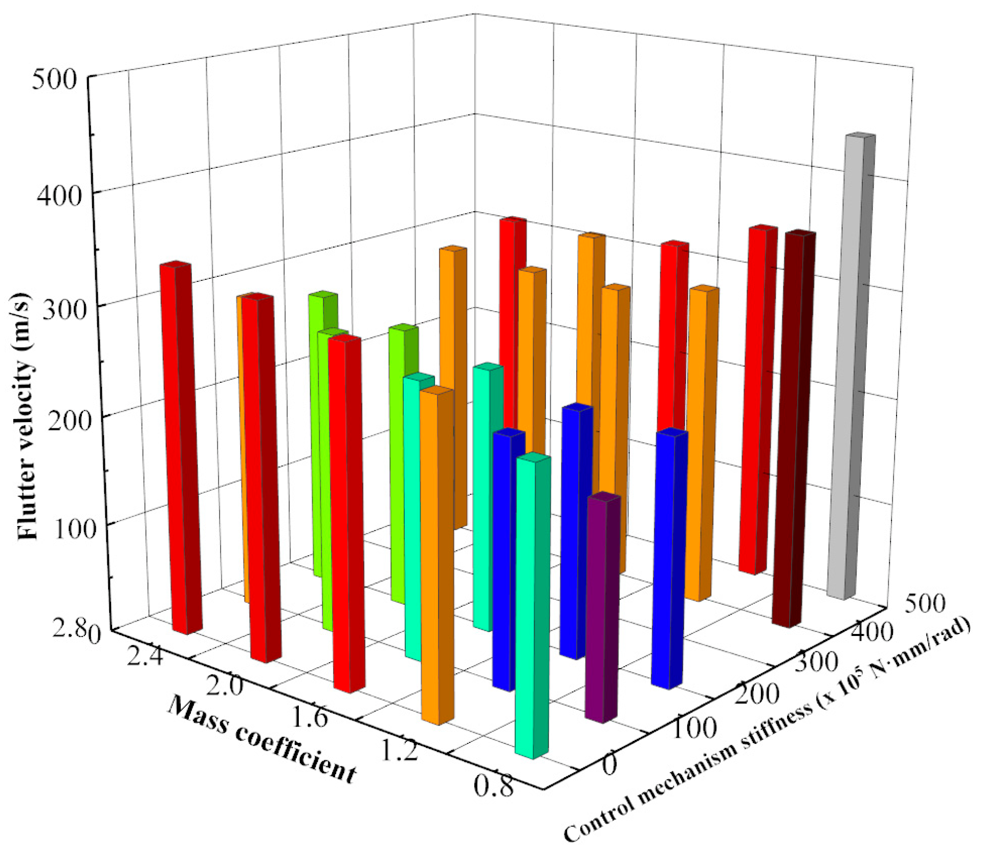
3.2. Variable Stiffness of Control Mechanism
3.3. Variable Mass of Aileron
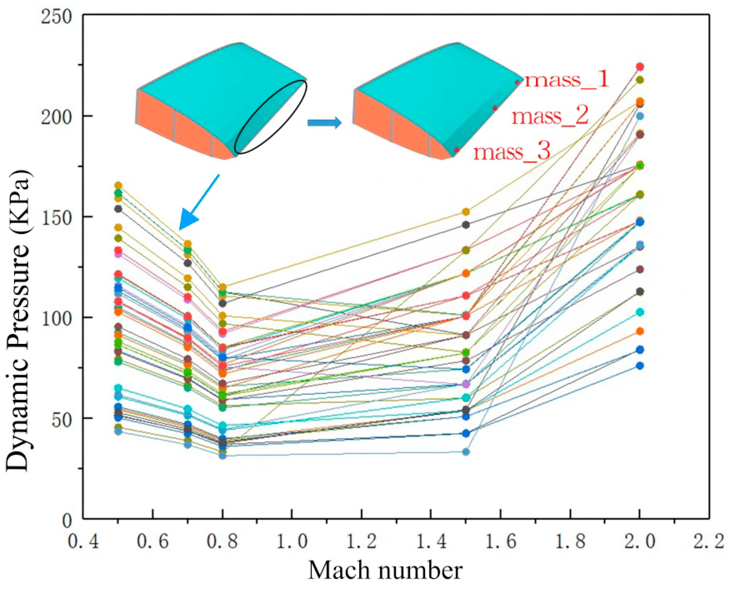
3.4. Variable Flight Altitude and Mach Number
4. Flutter Optimization
5. Results and Discussion
- (1)
- For the tri-wing aircraft, there are generally two flutter coupling modes: one is the symmetric combination of the SROA and STOA mode shapes; the other is the antisymmetric combination of the ASROA and ASTOA mode shapes.
- (2)
- According to the parametric analysis, the control mechanism stiffness and mass distribution of the aileron have more obvious effects on the flutter velocity than the structural stiffness of the aileron. Additionally, in the whole flight envelope, the flutter risk point is Mach 0.8.
- (3)
- The flutter optimization results show that increasing the mass of the aileron trailing edge could be conducive to improving the flutter boundary of large swept-back tri-wing aircraft.
6. Conclusions
- (1)
- The flutter mechanism type is one of the classical flutter mechanisms, and the flutter behavior can easily occur in the aileron part. The critical flutter velocity of the symmetric flutter mode shapes is generally larger than that the anti-symmetric flutter mode shapes.
- (2)
- The structural design of large swept-back tri-wing flight vehicles should be focused on the control mechanism stiffness and the mass distribution of the aileron. It is recommended to appropriately increase the control mechanism stiffness and mass at the trailing edge of the aileron.
- (3)
- The flutter optimization process can be used in the structural design process for aircraft with complex layouts, such as large swept-back tri-wing flight vehicles.
Author Contributions
Funding
Data Availability Statement
Conflicts of Interest
References
- Lee, B.H.K.; Price, S.J.; Wong, Y.S. Nonlinear Aeroelastic Analysis of Airfoils: Bifurcation and Chaos. Prog. Aerosp. Sci. 1999, 35, 205–334. [Google Scholar] [CrossRef]
- Zhang, X.; Kheiri, M.; Xie, W.F. Aeroservoelasticity of an Airfoil with Parametric Uncertainty and Subjected to Atmospheric Gusts. AIAA J. 2021, 59, 4326–4341. [Google Scholar] [CrossRef]
- Tang, D.; Dowell, E.H. Experimental Aeroelastic Models Design and Wind Tunnel Testing for Correlation with New Theory. Aerospace 2016, 3, 12. [Google Scholar] [CrossRef]
- Toffol, F.; Ricci, S. Preliminary Aero-Elastic Optimization of a Twin-Aisle Long-Haul Aircraft with Increased Aspect Ratio. Aerospace 2023, 10, 374. [Google Scholar] [CrossRef]
- Alkaya, C.; Alex Sam, A.; Pesyridis, A. Conceptual Advanced Transport Aircraft Design Configuration for Sustained Hypersonic Flight. Aerospace 2018, 5, 91. [Google Scholar] [CrossRef]
- Sills, J.W.; Allen, M.S. Historical Review of “Building Block Approach” in Validation for Human Space Flight. In Proceedings of the 37th IMAC, A Conference and Exposition on Structural Dynamics, Orlando, FL, USA, 28–31 January 2019. [Google Scholar] [CrossRef]
- Krummen, S.; Sippel, M. Effects of the rotational vehicle dynamics on the ascent flight trajectory of the SpaceLiner concept. CEAS Space J. 2019, 11, 161–172. [Google Scholar] [CrossRef]
- Raymer, D. Aircraft Design: A Conceptual Approach, 6th ed.; American Institute of Aeronautics and Astronautics: Reston, VA, USA, 2018. [Google Scholar]
- Sziroczak, D.; Smith, H. A Review of Design Issues Specific to Hypersonic Flight Vehicles. Prog. Aerosp. Sci. 2016, 84, 1–28. [Google Scholar] [CrossRef]
- Vedeneev, V.; Nesterov, V. Effect of nonequilibrium reacting flow on flutter at hypersonic flight speed. AIAA J. 2019, 57, 2222–2226. [Google Scholar] [CrossRef]
- Ricciardi, L.A.; Maddock, C.A.; Vasile, M. Direct solution of multi-objective optimal control problems applied to spaceplane mission design. J. Guid. Control Dyn. 2019, 42, 30–46. [Google Scholar] [CrossRef]
- Dai, Y.; Wang, Y.; Xu, X.; Yu, X. An Improved Method for Initial Sizing of Airbreathing Hypersonic Aircraft. Aerospace 2023, 10, 199. [Google Scholar] [CrossRef]
- Yuan, W.; Sandhu, R.; Poirel, D. Fully Coupled Aeroelastic Analyses of Wing Flutter towards Application to Complex Aircraft Configurations. J. Aerosp. Eng. 2021, 34, 04020117. [Google Scholar] [CrossRef]
- Paez, C. The Development of the X-37 Re-Entry Vehicle. In Proceedings of the 40th AIAA/ASME/SAE/ASEE Joint Propulsion Conference and Exhibit, Fort Lauderdale, FL, USA, 11–14 July 2004. [Google Scholar] [CrossRef]
- Nicolai, L.M.; Carichner, G.E. Fundamentals of Aircraft and Airship Design, Volume 1—Aircraft Design; American Institute of Aeronautics and Astronautics: Reston, VA, USA, 2010. [Google Scholar]
- Ai, X.; Bai, Y.; Qian, W.; Li, Y.; Chen, X. Experimental Aeroelastic Investigation of an All-Movable Horizontal Tail Model with Bending and Torsion Free-Plays. Aerospace 2023, 10, 434. [Google Scholar] [CrossRef]
- Tian, W.; Gu, Y.; Liu, H.; Wang, X.; Yang, Z.; Li, Y.; Li, P. Nonlinear Aeroservoelastic Analysis of a Supersonic Aircraft with Control Fin Free-play by Component Mode Synthesis Technique. J. Sound. Vib. 2021, 493, 115835. [Google Scholar] [CrossRef]
- Wu, Z.; Yang, N.; Yang, C. Identification of Nonlinear Structures by the Conditioned Reverse Path Method. J. Aircr. 2015, 52, 373–386. [Google Scholar] [CrossRef]
- Sleesongsom, S.; Kumar, S.; Bureerat, S. Multi-Objective Reliability-Based Partial Topology Optimization of a Composite Aircraft Wing. Symmetry 2023, 15, 305. [Google Scholar] [CrossRef]
- Sleesongsom, S.; Kumar, S.; Bureerat, S. Two-Step Multi-Objective Reliability-Based Design Optimization of Aircraft Wing Structures. Symmetry 2022, 14, 2125. [Google Scholar] [CrossRef]
- Jonsson, E. High-Fidelity Aerostructural Optimization of FlexibleWings with Flutter Constraints. Ph.D. Thesis, University of Michigan, Ann Arbor, MI, USA, 2020. [Google Scholar]
- Jonsson, E.; Mader, C.A.; Kennedy, G.J.; Martins, J.R.R.A. Computational Modeling of Flutter Constraint for High-Fidelity Aero-structural Optimization. In Proceedings of the 2019 AIAA/ASCE/AHS/ASC Structures, Structural Dynamics, and Materials Conference, Austin, TX, USA, 18–21 April 2019. AIAA Paper 2019-2354. [Google Scholar] [CrossRef]
- Zhang, M.; Xu, F. Tuned mass damper for self-excited vibration control: Optimization involving nonlinear aeroelastic effect. J. Wind Eng. Ind. Aerodyn. 2022, 220, 104836. [Google Scholar] [CrossRef]
- Jonsson, E.; Riso, C.; Lupp, C.A.; Cesnik, C.E.; Martins, J.R.; Epureanu, B.I. Flutter and post-flutter constraints in aircraft design optimization. Prog. Aerosp. Sci. 2019, 109, 100537. [Google Scholar] [CrossRef]
- Wang, W.; Qian, W.; Bai, Y.; Wang, K. Numerical studies on the thermal-fluid-structure coupling analysis method of hypersonic flight vehicle. Therm. Sci. Eng. Prog. 2023, 40, 101792. [Google Scholar] [CrossRef]
- Harder, R.L.; Desmarais, R.N. Interpolation using surface splines. J. Aircr. 1972, 9, 189–191. [Google Scholar] [CrossRef]
- Rodden, W.P.; Johnson, E.H. MSC NASTRAN Version 68 Aeroelastic Analysis User’s Guide; MSC Software Corporation: Santa Ana, CA, USA, 2004. [Google Scholar]
- Yuan, W.; Zhang, X.; Poirel, D.C. Flutter analysis solution stabilization for the PK-method. In Proceedings of the AIAA Aviation 2021 Forum, Virtual Event, 2–6 August 2021. [Google Scholar] [CrossRef]
- Chen, Z.Q.; Zhao, Y.H. Aerothermoelastic Analysis of a Hypersonic Vehicle Based on Thermal Modal Reconstruction. Int. J. Aerosp. Eng. 2019, 2019, 8384639. [Google Scholar] [CrossRef]
- Yuan, W.; Zhang, X. Numerical Stabilization for Flutter Analysis Procedure. Aerospace 2023, 10, 302. [Google Scholar] [CrossRef]
- Kleijnen, P.C. Regression and Kriging metamodels with their experimental designs in simulation: A review. Eur. J. Oper. Res. 2017, 256, 1–16. [Google Scholar] [CrossRef]


| Mode Shape | Frequency/Hz |
|---|---|
| 1st bending of fuselage (1st BOF) | 22.72 |
| Symmetric rotation of aileron (SROA) | 28.22 |
| Anti-symmetric rotation of aileron (ASROA) | 28.51 |
| Symmetric torsion of aileron (STOA) | 39.40 |
| Anti-symmetric torsion of aileron (ASTOA) | 44.01 |
| 2nd bending of fuselage (2nd BOF) | 58.05 |
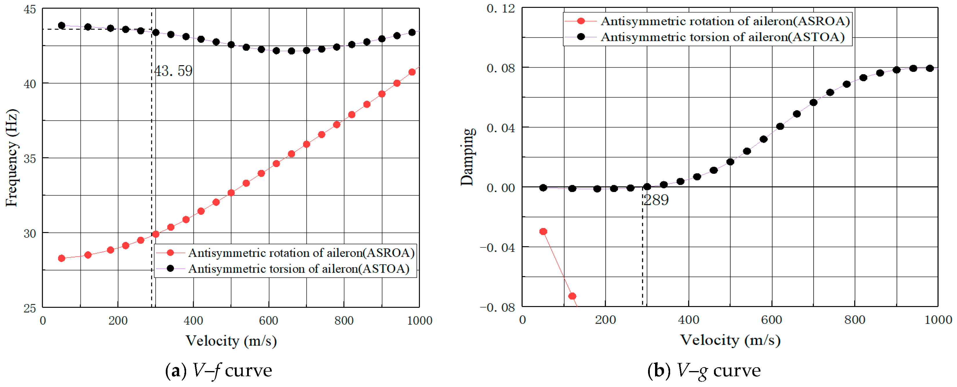
| Mode Shapes Combination | Flutter Coupling Modes | Flutter Speed (m/s) | Flutter Frequency (Hz) |
|---|---|---|---|
| Six modes | See Table 1 | 225 | 39.11 |
| 289 | 43.60 | ||
| Symmetric modes | SROA/28.22 Hz and STOA/39.40 Hz | 227 | 39.11 |
| Anti-symmetric modes | ASROA/28.51 Hz and ASTOA/44.01 Hz | 288 | 43.59 |
Disclaimer/Publisher’s Note: The statements, opinions and data contained in all publications are solely those of the individual author(s) and contributor(s) and not of MDPI and/or the editor(s). MDPI and/or the editor(s) disclaim responsibility for any injury to people or property resulting from any ideas, methods, instructions or products referred to in the content. |
© 2023 by the authors. Licensee MDPI, Basel, Switzerland. This article is an open access article distributed under the terms and conditions of the Creative Commons Attribution (CC BY) license (https://creativecommons.org/licenses/by/4.0/).
Share and Cite
Wang, W.; Qian, W.; Ai, X.; Bai, Y. Flutter Optimization of Large Swept-Back Tri-Wing Flight Vehicles. Aerospace 2023, 10, 854. https://doi.org/10.3390/aerospace10100854
Wang W, Qian W, Ai X, Bai Y. Flutter Optimization of Large Swept-Back Tri-Wing Flight Vehicles. Aerospace. 2023; 10(10):854. https://doi.org/10.3390/aerospace10100854
Chicago/Turabian StyleWang, Weiji, Wei Qian, Xinyu Ai, and Yuguang Bai. 2023. "Flutter Optimization of Large Swept-Back Tri-Wing Flight Vehicles" Aerospace 10, no. 10: 854. https://doi.org/10.3390/aerospace10100854