
Implementation of Fuel Cells in Aviation from a Maintenance, Repair and Overhaul Perspective


Abstract
:1. Introduction
- 1.
- How can fuel cells be maintained, repaired, inspected and overhauled effectively in aviation?
- 2.
- How well are MRO providers equipped to perform the necessary MRO tasks from a business model standpoint?
2. State of the Art of Fuel Cell MRO
2.1. Fuel Cell Types
2.2. Role of Fuel Cell MRO
2.3. Fuel Cell MRO in Automotive and Aviation
3. Technological Analysis of Fuel-Cell MRO in Aviation
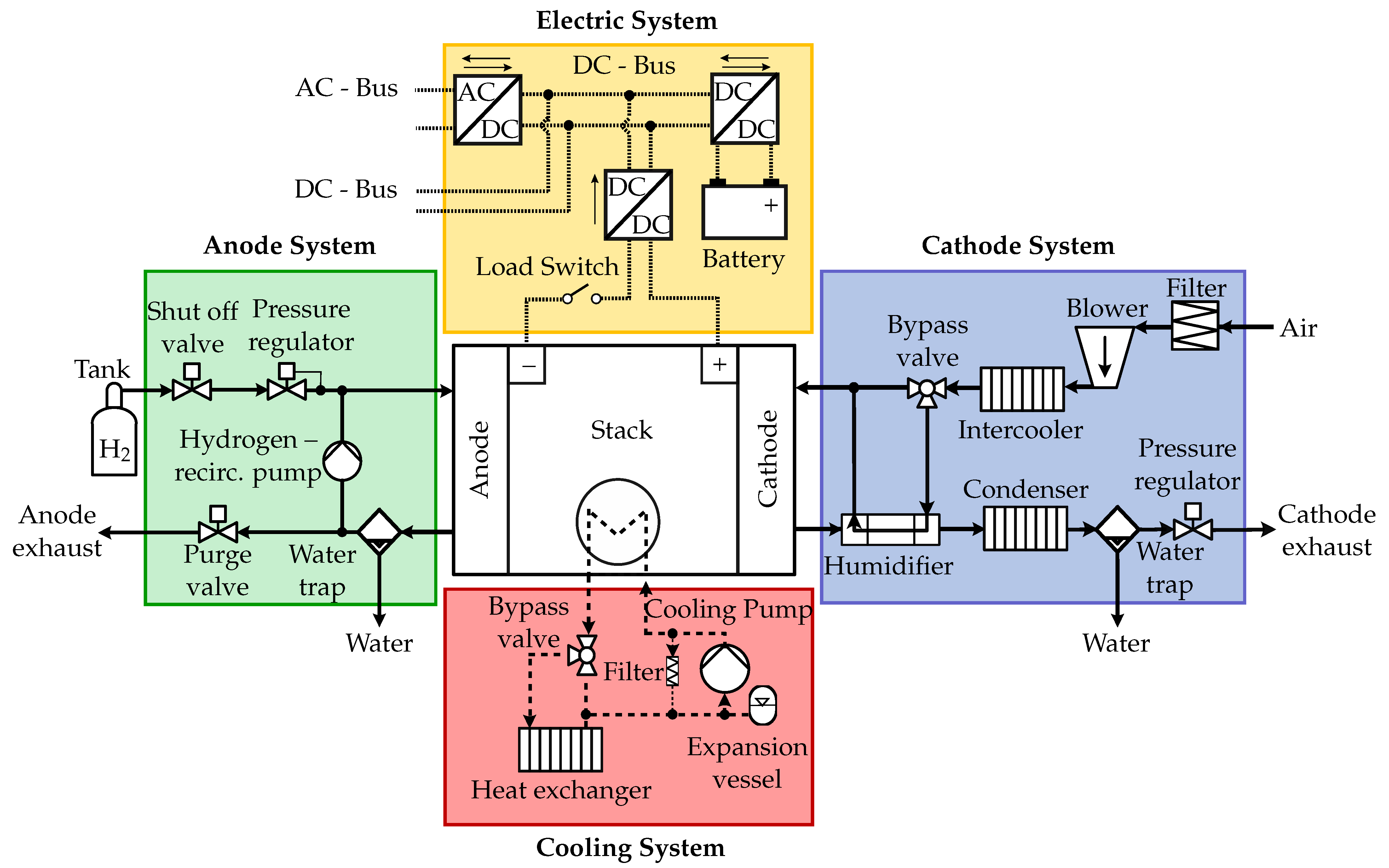
3.1. Surrounding System
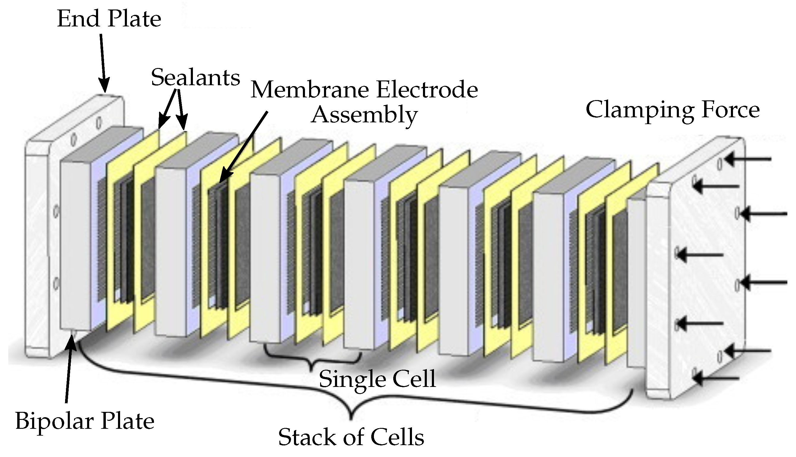
3.2. Stack
4. Implications for MRO Providers
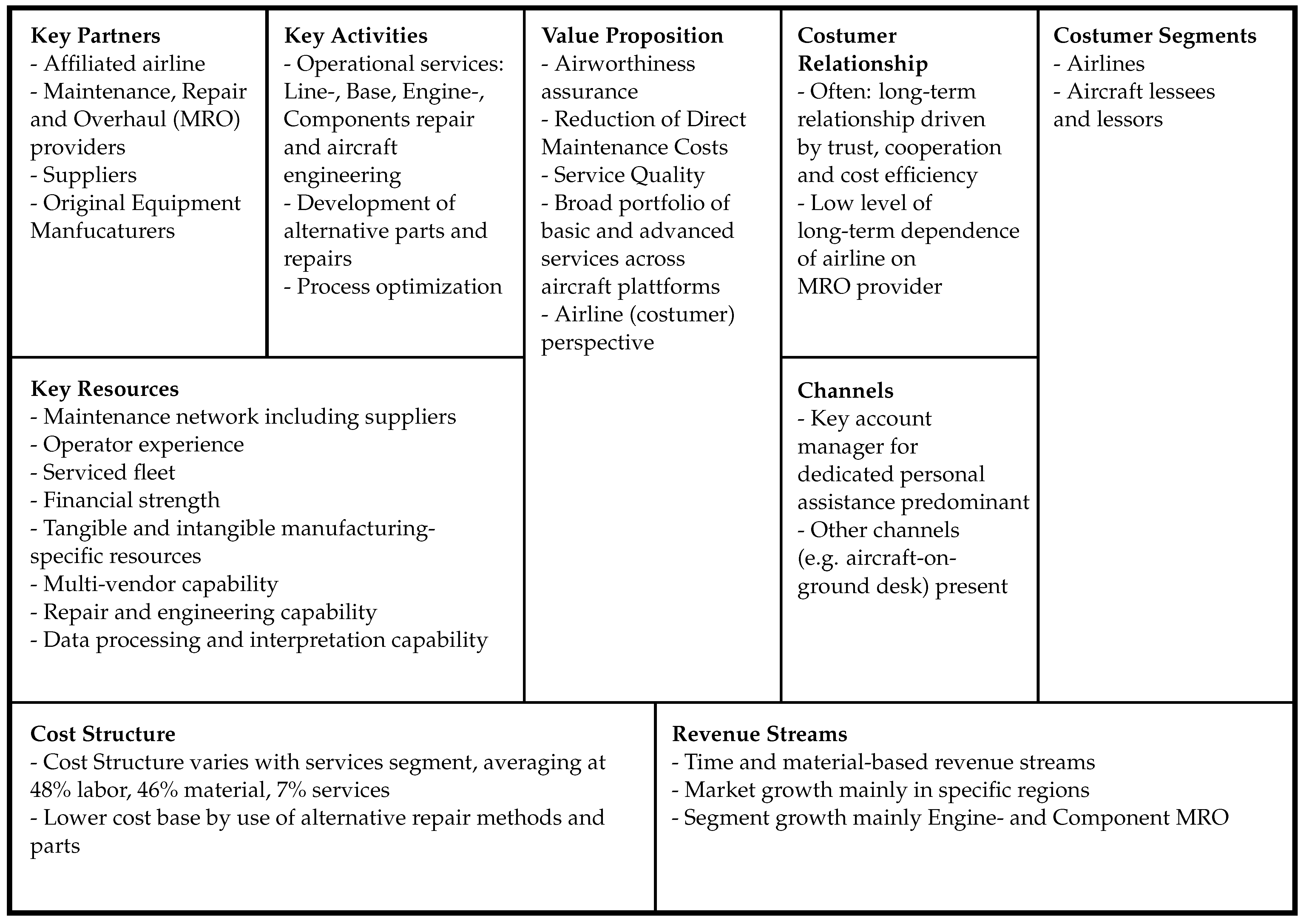
4.1. Business Model
A business model describes the rationale of how an organization creates, delivers, and captures value [106].
4.2. Key Resources
5. Conclusions
Author Contributions
Funding
Institutional Review Board Statement
Informed Consent Statement
Data Availability Statement
Conflicts of Interest
Appendix A

| Check | Interval | Task Description | MH [h] | Downtime [h] |
|---|---|---|---|---|
| Daily | every | Check ground fault monitor resistance and replace water or de-ionizing filter if required | 1.25 | 0.25 |
| Check stack vent fans | ||||
| Inspect burst disk vent cap | ||||
| Check leak indicators and sensors, and calibrate system if required | ||||
| Check for fluid leaks or puddles | ||||
| Inspect air intake, air exhaust and canopies | ||||
| Weekly | every | Perform leak-down test | 4.5 | 1 |
| Check cell voltage monitor | ||||
| Perform fuel delivery circuit leak test | ||||
| Inspect fire suppression sensors | ||||
| Clean stack vent fan filters | ||||
| Inspect stack air inlet filters and replace if required | ||||
| Inspect filter minder and replace air intake filter if indicated | ||||
| Check stack coolant level | ||||
| Inspect hoses and tubes | ||||
| A-Check | every | Perform fuel cell external and transfer leak tests | 20 | 10 |
| Perform glycol system integrity test | ||||
| Check power cable connections | ||||
| Perform high- and motive-pressure circuit leak test | ||||
| Inspect high, motive and fuel delivery circuit components | ||||
| Compare fuel pressure transducer readings | ||||
| Inspect radiator | ||||
| A-Check | every 2nd | Check the motive pressure regulator solenoid valve | 10 | 10 |
| Perform ground integrity tests | ||||
| Inspect and/or replace air intake filter | ||||
| every 4th | Inspect heat exchanger (vaporizer) | 80 | 10 | |
| Inspect primary and secondary relive valve and vent line | ||||
| Inspect pressure regulator and boost pumps | ||||
| Inspect vacuum pump system, N2 purge system and high pressure pump | ||||
| Inspect burst discs | ||||
| every 8th | Replace pressure regulator diaphragm, seal replacement | 20 | 10 | |
| Perform fire suppression system tests | ||||
| Inspect power train and stack vibration mounts | ||||
| C-Check | every | Exchange of humidifier | 9 | 3 |
| every 2nd | Exchange of compressor | 9 | 3 | |
| every 3rd | Exchange of primary and secondary relive valve and vent line | 30 | 5 | |
| Exchange of pressure regulator and boost pumps | ||||
| Exchange of heat exchanger (vaporizer) | ||||
| Exchange of vacuum pump system, N2 purge system and high pressure pump | ||||
| Exchange of burst disc | ||||
| every 4th | Exchange of fuel-cell stacks and compressor power converter | 72 | 24 |
References
- International Air Transport Association. Fact Sheet: Climate Change & CORSIA. Available online: https://www.iata.org/contentassets/713a82c7fbf84947ad536df18d08ed86/fact-sheet-climate-change.pdf (accessed on 11 November 2022).
- International Air Transport Association. Our Commitment to Fly Net Zero by 2050. Available online: https://www.iata.org/en/programs/environment/flynetzero/ (accessed on 11 November 2022).
- International Civil Aviation Organization. Consolitated Statement of Continuing ICAO Policies and Practices Related to Environmental Protection Climate Change: Resolution A40-18. Available online: https://www.icao.int/environmental-protection/Documents/Assembly/Resolution_A40-18_Climate_Change.pdf (accessed on 11 November 2022).
- European Commission. Reducing Emissions from Aviation. Available online: https://ec.europa.eu/clima/eu-action/transport-emissions/reducing-emissions-aviation_en (accessed on 11 November 2022).
- European Commission. Directorate-General for Mobility and Transport, Directorate-General for Research and Innovation. In Flightpath 2050: Europe’s Vision for Aviation: Maintaining Global Leadership and Serving Society’s Needs; Publications Office: Brussels, Belgium, 2011. [Google Scholar] [CrossRef]
- Rao, A.G.; Yin, F.; Werij, H. Energy Transition in Aviation: The Role of Cryogenic Fuels. Aerospace 2020, 7, 181. [Google Scholar] [CrossRef]
- Airbus. ZEROe: Towards the World’s First Zero-Emission Commercial Aircraft. Available online: https://www.airbus.com/en/innovation/zero-emission/hydrogen/zeroe (accessed on 9 November 2022).
- Bruce, S.; Temminghoff, M.; Hayward, J.; Palfreyman, D.; Munnings, C.; Burke, N.; Creasey, S. Opportunities for Hydrogen in Commercial Aviation—CSIRO. Available online: https://www.csiro.au/en/work-with-us/services/consultancy-strategic-advice-services/CSIRO-futures/Energy-and-Resources/hydrogen-commercial-aviation (accessed on 10 November 2022).
- Boeing Prepares Fuel Cell Demonstrator Airplane for Ground and Flight Testing. Available online: https://boeing.mediaroom.com/2007-03-27-Boeing-Prepares-Fuel-Cell-Demonstrator-Airplane-for-Ground-and-Flight-Testing (accessed on 9 November 2022).
- Boeing Successfully Flies Fuel Cell-Powered Airplane. Available online: https://www.boeing.com/aboutus/environment/environmental_report/_inc/flash-2-1-2.html (accessed on 9 November 2022).
- DLR and Airbus Testing Hydrogen PEM Fuel Cell Auxiliary Power System in A320. Available online: https://www.greencarcongress.com/2008/05/dlr-and-airbus.html (accessed on 9 November 2022).
- Antares DLR-H2—Out of op Er a tion. Available online: https://www.dlr.de/content/en/articles/aeronautics/research-fleet-infrastructure/dlr-research-aircraft/antares-dlr-h2-out-of-operation.html (accessed on 9 November 2022).
- ENvironmentally Friendly Inter City Aircraft powered by Fuel Cells (ENFICA-FC). Available online: http://www.enfica-fc.polito.it/ (accessed on 9 November 2022).
- HY4 Aircraft. Available online: https://www.aerospace-technology.com/projects/hy4-aircraft/ (accessed on 9 November 2022).
- Choi, Y.; Lee, J. Estimation of Liquid Hydrogen Fuels in Aviation. Aerospace 2022, 9, 564. [Google Scholar] [CrossRef]
- ZeroAvia Homepage. Available online: https://www.zeroavia.com/ (accessed on 11 November 2022).
- Deutsche Aircraft aims for hydrogen aviation. Fuel Cells Bull. 2021, 2021, 7. [CrossRef]
- Deutsches Zentrum für Luft- und Raumfahrt e.V. BMWK fördert Projekt Zurweiterentwicklung Derwasserstoff-Brennstoffzellen-Technologie. Available online: https://www.dlr.de/content/de/artikel/news/2022/02/20220405-projekt-weiterentwicklung-wasserstoff-brennstoffzellen-technologie.html (accessed on 11 November 2022).
- Chiesa, P.; Lozza, G.; Mazzocchi, L. Using Hydrogen as Gas Turbine Fuel. J. Eng. Gas Turbine Power 2005, 127, 73–80. [Google Scholar] [CrossRef]
- Haglind, F.; Singh, R. Design of Aero Gas Turbines Using Hydrogen. J. Eng. Gas Turbine Power 2006, 128, 754–764. [Google Scholar] [CrossRef]
- Baharozu, E.; Soykan, G.; Ozerdem, M.B. Future aircraft concept in terms of energy efficiency and environmental factors. Energy 2017, 140, 1368–1377. [Google Scholar] [CrossRef]
- Publications Office of the European Union. Hydrogen-Powered Aviation: A Fact-Based Study of Hydrogen Technology, Economics, and Climate Impact by 2050; Publications Office: Luxembourg, 2020. [Google Scholar] [CrossRef]
- Lindorfer, J.; Reiter, G.; Tichler, R.; Steinmüller, H. 14—Hydrogen fuel, fuel cells, and methane. In Managing Global Warming; Letcher, T.M., Ed.; Elsevier Science & Technology: San Diego, CA, USA, 2018; pp. 419–453. [Google Scholar] [CrossRef]
- Hoelzen, J.; Silberhorn, D.; Zill, T.; Bensmann, B.; Hanke-Rauschenbach, R. Hydrogen-powered aviation and its reliance on green hydrogen infrastructure—Review and research gaps. Int. J. Hydrogen Energy 2022, 47, 3108–3130. [Google Scholar] [CrossRef]
- Rindlisbacher, T. Auf Dem Weg Zum Klimafreundlichen Fliegen. Available online: https://www.ssm-studies.ch/fileadmin/pdf/SSM/Blogsammlung/Antriebstechnologien/200804_Auf_dem_Weg_zum_klimafreundlichen_Fliegen.pdf (accessed on 11 November 2022).
- Sforza, P.M. Chapter 8—Refined Weight and Balance Estimate. In Commercial Airplane Design Principles; Sforza, P.M., Ed.; Butterworth-Heinemann: Boston, MA, USA, 2014; pp. 301–347. [Google Scholar] [CrossRef]
- Schröder, M.; Becker, F.; Kallo, J.; Gentner, C. Optimal operating conditions of PEM fuel cells in commercial aircraft. Int. J. Hydrogen Energy 2021, 46, 33218–33240. [Google Scholar] [CrossRef]
- Agostini, A.; Belmonte, N.; Masala, A.; Hu, J.; Rizzi, P.; Fichtner, M.; Moretto, P.; Luetto, C.; Sgroi, M.; Baricco, M. Role of hydrogen tanks in the life cycle assessment of fuel cell-based auxiliary power units. Appl. Energy 2018, 215, 1–12. [Google Scholar] [CrossRef]
- Banan, R.; Bazylak, A.; Zu, J. Combined effects of environmental vibrations and hygrothermal fatigue on mechanical damage in PEM fuel cells. Int. J. Hydrogen Energy 2015, 40, 1911–1922. [Google Scholar] [CrossRef]
- Office of Energy Efficiency & Renewable Energy. Hydrogen Storage. Available online: https://www.energy.gov/eere/fuelcells/hydrogen-storage (accessed on 11 November 2022).
- Wehrspohn, J.; Rahn, A.; Papantoni, V.; Silberhorn, D.; Burschyk, T.; Schröder, M.; Linke, F.; Dahlmann, K.; Kühlen, M.; Wicke, K.; et al. A Detailed and Comparative Economic Analysis of Hybrid-Electric Aircraft Concepts Considering Environmental Assessment Factors. In Proceedings of the AIAA Aviation Forum, Chicago, IL, USA, 27 June–1 July 2022; American Institute of Aeronautics and Astronautics: Reston, VA, USA, 2022. [Google Scholar] [CrossRef]
- Fuel Cells and Hydrogen 2 Joint Undertaking (FCH 2 JU): Addendum to the Multi—Annual Work Plan 2014–2020. Available online: https://www.fch.europa.eu/sites/default/files/MAWP%20final%20version_endorsed%20GB%2015062018%20%28ID%203712421%29.pdf (accessed on 11 November 2022).
- Whyatt, G.A.; Chick, L.A. Electrical Generation for More-Electric Aircraft Using Solid Oxide Fuel Cells. Available online: https://www.energy.gov/sites/default/files/2014/03/f9/sofc_for_aircraft_pnnl_2012.pdf (accessed on 11 November 2022).
- Campanari, S.; Manzolini, G.; Beretti, A.; Wollrab, U. Performance Assessment of Turbocharged Pem Fuel Cell Systems for Civil Aircraft Onboard Power Production. J. Eng. Gas Turbine Power 2008, 130, 021701. [Google Scholar] [CrossRef] [Green Version]
- Dyantyi, N.; Parsons, A.; Bujlo, P.; Pasupathi, S. Behavioural study of PEMFC during start-up/shutdown cycling for aeronautic applications. Mater. Renew. Sustain. Energy 2019, 8, 4. [Google Scholar] [CrossRef] [Green Version]
- Keim, M.; Kallo, J.; Friedrich, K.A.; Werner, C.; Saballus, M.; Gores, F. Multifunctional fuel cell system in an aircraft environment: An investigation focusing on fuel tank inerting and water generation. Aerosp. Sci. Technol. 2013, 29, 330–338. [Google Scholar] [CrossRef] [Green Version]
- Renouard-Vallet, G.; Saballus, M.; Schumann, P.; Kallo, J.; Friedrich, K.A.; Müller-Steinhagen, H. Fuel cells for civil aircraft application: On-board production of power, water and inert gas. Chem. Eng. Res. Des. 2012, 90, 3–10. [Google Scholar] [CrossRef]
- Department of Energy, U.S.A. Automotive Fuel Cell Targets and Status. Available online: https://www.hydrogen.energy.gov/pdfs/20005-automotive-fuel-cell-targets-status.pdf (accessed on 11 November 2022).
- Haji Hosseinloo, A.; Ehteshami, M.M. Shock and vibration effects on performance reliability and mechanical integrity of proton exchange membrane fuel cells: A critical review and discussion. J. Power Sources 2017, 364, 367–373. [Google Scholar] [CrossRef]
- Wang, J.; Wang, H.; Fan, Y. Techno-Economic Challenges of Fuel Cell Commercialization. Engineering 2018, 4, 352–360. [Google Scholar] [CrossRef]
- Knowles, M.; Baglee, D.; Morris, A.; Ren, Q. The State of the Art in Fuel Cell Condition Monitoring and Maintenance. World Electr. Veh. J. 2010, 4, 487–494. [Google Scholar] [CrossRef] [Green Version]
- Alaswad, A.; Omran, A.; Sodre, J.R.; Wilberforce, T.; Pignatelli, G.; Dassisti, M.; Baroutaji, A.; Olabi, A.G. Technical and Commercial Challenges of Proton-Exchange Membrane (PEM) Fuel Cells. Energies 2021, 14, 144. [Google Scholar] [CrossRef]
- Department of Energy, U.S.A. Fuel Cell System Cost—2017. Available online: https://www.hydrogen.energy.gov/pdfs/17007_fuel_cell_system_cost_2017.pdf (accessed on 11 November 2022).
- Whiteley, M.; Dunnett, S.; Jackson, L. Failure Mode and Effect Analysis, and Fault Tree Analysis of Polymer Electrolyte Membrane Fuel Cells. Int. J. Hydrogen Energy 2016, 41, 1187–1202. [Google Scholar] [CrossRef] [Green Version]
- Li, X.; Li, J.; Xu, L.; Yang, F.; Hua, J.; Ouyang, M. Performance analysis of proton-exchange membrane fuel cell stacks used in Beijing urban-route buses trial project. Int. J. Hydrogen Energy 2010, 35, 3841–3847. [Google Scholar] [CrossRef]
- Liang, J.M.; Jian, Q.F. Decay Analysis of a 5kW PEMFC Stack in Sightseeing Bus. Appl. Mech. Mater. 2013, 401-403, 1826–1829. [Google Scholar] [CrossRef]
- Placca, L.; Kouta, R. Fault tree analysis for PEM fuel cell degradation process modelling. Int. J. Hydrogen Energy 2011, 36, 12393–12405. [Google Scholar] [CrossRef]
- Kazula, S.; de Graaf, S.; Enghardt, L. Review of Fuel Cell Technologies and Evaluation of their Potential and Challenges for Electrified Propulsion Systems in Commercial Aviation. In Proceedings of the Global Power and Propulsion Society 2022, Chania, Greece, 12–14 September 2022. [Google Scholar] [CrossRef]
- Cigolotti, V.; Genovese, M.; Fragiacomo, P. Comprehensive Review on Fuel Cell Technology for Stationary Applications as Sustainable and Efficient Poly-Generation Energy Systems. Energies 2021, 14, 4963. [Google Scholar] [CrossRef]
- Bernay, C.; Marchand, M.; Cassir, M. Prospects of different fuel cell technologies for vehicle applications. J. Power Sources 2002, 108, 139–152. [Google Scholar] [CrossRef]
- Tornabene, R.; Wang, X.Y.; Steffen, C.J., Jr.; Freeh, J.E. Development of Parametric Mass and Volume Models for an Aerospace SOFC/Gas Turbine Hybrid System. Available online: https://ntrs.nasa.gov/api/citations/20050203845/downloads/20050203845.pdf (accessed on 11 November 2022).
- Fernandes, M.D.; Andrade, S.D.P.; Bistritzki, V.N.; Fonseca, R.M.; Zacarias, L.G.; Gonçalves, H.; de Castro, A.F.; Domingues, R.Z.; Matencio, T. SOFC-APU systems for aircraft: A review. Int. J. Hydrogen Energy 2018, 43, 16311–16333. [Google Scholar] [CrossRef]
- Hjuler, H.A.; Azizi, K.; Seselj, N.; Martinez Alfaro, S.; Garcia, H.R.; Gromadskyi, D.; Hromadska, L.; Primdahl, S.; Jensen, J.O.; Li, Q.; et al. High-Temperature PEM Fuel Cells: Towards Decreasing the Pt Loadings. Meet. Abstr. 2021, MA2021-02, 1196. [Google Scholar] [CrossRef]
- Mokrani, Z.; Rekioua, D.; Mebarki, N.; Rekioua, T.; Bacha, S. Proposed energy management strategy in electric vehicle for recovering power excess produced by fuel cells. Int. J. Hydrogen Energy 2017, 42, 19556–19575. [Google Scholar] [CrossRef]
- Wang, C.; Li, Z.; Outbib, R.; Dou, M.; Zhao, D. A novel long short-term memory networks-based data-driven prognostic strategy for proton exchange membrane fuel cells. Int. J. Hydrogen Energy 2022, 47, 10395–10408. [Google Scholar] [CrossRef]
- He, K.; Zhang, C.; He, Q.; Wu, Q.; Jackson, L.; Mao, L. Effectiveness of PEMFC historical state and operating mode in PEMFC prognosis. Int. J. Hydrogen Energy 2020, 45, 32355–32366. [Google Scholar] [CrossRef]
- Chen, K.; Laghrouche, S.; Djerdir, A. Aging prognosis model of proton exchange membrane fuel cell in different operating conditions. Int. J. Hydrogen Energy 2020, 45, 11761–11772. [Google Scholar] [CrossRef]
- Gonnet, A.E.; Robles, S.; Moro, L. Performance study of a PEM fuel cell. Int. J. Hydrogen Energy 2012, 37, 14757–14760. [Google Scholar] [CrossRef]
- Hashimasa, Y.; Numata, T. Comparison of test results on load cycle durability of polymer electrolyte fuel cell cathode catalysts. Int. J. Hydrogen Energy 2015, 40, 11543–11549. [Google Scholar] [CrossRef]
- Deutsches Zentrum für Luft- und Raumfahrt, e.V. Project BALIS—DLR Developing and Testing Fuel Cells in the Megawatt Range for Air Transport. Available online: https://www.dlr.de/content/en/articles/news/2021/01/20210121_balis-project-funding.html (accessed on 11 November 2022).
- Fuel Cell Maintenance and the “Moving Parts” Fallacy. Available online: https://www.ballardmotivesolutions.com/insights/fuel-cell-maintenance-and-the-moving-parts-fallacy (accessed on 9 November 2022).
- Wirths, O. Business Model Innovation in the Aerospace Industry: Strategic Options for Maintenance, Repair and Overhaul Firms. Ph.D. Thesis, Universität zu Köln, Köln, Germany, 2019. [Google Scholar]
- Viera, D.R.; Loures, P.L. Maintenance, Repair and Overhaul (MRO) Fundamentals and Strategies: An Aeronautical Industry Overview. Int. J. Comput. Appl. 2016, 135, 21–29. [Google Scholar] [CrossRef]
- Laporte, A. Fact Sheet|Fuel Cells. Available online: https://www.eesi.org/papers/view/fact-sheet-fuel-cells (accessed on 11 November 2022).
- Han, J.; Charpentier, J.F.; Tang, T. State of the art of fuel cells for ship applications. In Proceedings of the IEEE International Symposium on Industrial Electronics, Hangzhou, China, 28–31 May 2012; pp. 1456–1461. [Google Scholar] [CrossRef]
- Hou, Y.; Hao, D.; Shen, J.; Li, P.; Zhang, T.; Wang, H. Effect of strengthened road vibration on performance degradation of PEM fuel cell stack. Int. J. Hydrogen Energy 2016, 41, 5123–5134. [Google Scholar] [CrossRef]
- Deutsche Gesetzliche Unfallversicherung. Wasserstoffsicherheit in Werkstätten: DGUV Regel 209-072. Available online: https://publikationen.dguv.de/regelwerk/dguv-informationen/265/wasserstoffsicherheit-in-werkstaetten (accessed on 11 November 2022).
- Deutsche Gesetzliche Unfallversicherung. Gasantriebsysteme in Fahrzeugen-Qualifizierung für Arbeiten an Fahrzeugen mit Gasantrieb: FBHM-099. Available online: https://publikationen.dguv.de/regelwerk/fachbereich-aktuell/holz-und-metall/3528/fbhm-099-gasantriebsysteme-in-fahrzeugen-qualifizierung-fuer-arbeiten-an-fahrzeugen-mit-gasantrieb (accessed on 11 November 2022).
- Thomson, R.; Weichenhain, U.; Sachdeva, N.; Kaufmann, M. Hydrogen: A Future Fuel for Aviation? Available online: https://www.rolandberger.com/en/Insights/Publications/Hydrogen-A-future-fuel-for-aviation.html (accessed on 11 November 2022).
- Eid, A.; El-Kishky, H.; Abdel-Salam, M.; El-Mohandes, T. Modeling and characterization of an aircraft electric power system with a fuel cell-equipped APU paralleled at main AC bus. In Proceedings of the IEEE International Power Modulator and High Voltage Conference 1, Atlanta, GA, USA, 23–27 May 2010; pp. 229–232. [Google Scholar] [CrossRef]
- Hoenicke, P.; Ghosh, D.; Muhandes, A.; Bhattacharya, S.; Bauer, C.; Kallo, J.; Willich, C. Power management control and delivery module for a hybrid electric aircraft using fuel cell and battery. Energy Convers. Manag. 2021, 244, 114445. [Google Scholar] [CrossRef]
- An, J.H.; Kwon, D.Y.; Jeon, K.S.; Tyan, M.; Lee, J.W. Advanced Sizing Methodology for a Multi-Mode eVTOL UAV Powered by a Hydrogen Fuel Cell and Battery. Aerospace 2022, 9, 71. [Google Scholar] [CrossRef]
- Pahon, E.; Jemei, S.; Steiner, N.Y.; Hissel, D. Effect of Load Cycling on the Performance of Fuel Cell Stacks. In Proceedings of the 2019 IEEE Vehicle Power and Propulsion Conference (VPPC), Hanoi, Vietnam, 14–17 October 2019; pp. 1–4. [Google Scholar] [CrossRef]
- Department of Energy, U.S.A. On-Road Transit Bus Fuel Cell Stack Durability. Available online: https://www.hydrogen.energy.gov/pdfs/20008-fuel-cell-bus-durability.pdf (accessed on 11 November 2022).
- Multi-Annual Work Program 2014–2020. Available online: https://www.fch.europa.eu/sites/default/files/FCH%202%20JU%20MAWP-%20final%20%28ID%204221004%29.pdf (accessed on 11 November 2022).
- Correa, G.; Borello, F.; Santarelli, M. Sensitivity analysis of temperature uncertainty in an aircraft PEM fuel cell. Int. J. Hydrogen Energy 2011, 36, 14745–14758. [Google Scholar] [CrossRef]
- Lapeña-Rey, N.; Mosquera, J.; Bataller, E.; Ortí, F. First Fuel-Cell Manned Aircraft. J. Aircr. 2010, 47, 1825–1835. [Google Scholar] [CrossRef]
- Marinaro, G.; Di Lorenzo, G.; Pagano, A. From a Battery-Based to a PEM Fuel Cell-Based Propulsion Architecture on a Lightweight Full Electric Aircraft: A Comparative Numerical Study. Aerospace 2022, 9, 408. [Google Scholar] [CrossRef]
- Suewatanakul, S.; Porcarelli, A.; Olsson, A.; Grimler, H.; Chiche, A.; Mariani, R.; Lindbergh, G. Conceptual Design of a Hybrid Hydrogen Fuel Cell/Battery Blended-Wing-Body Unmanned Aerial Vehicle—An Overview. Aerospace 2022, 9, 275. [Google Scholar] [CrossRef]
- Kim, T.; Kwon, S. Design and development of a fuel cell-powered small unmanned aircraft. Int. J. Hydrogen Energy 2012, 37, 615–622. [Google Scholar] [CrossRef]
- Bradley, T.H.; Moffitt, B.A.; Mavris, D.N.; Parekh, D.E. Development and experimental characterization of a fuel cell powered aircraft. J. Power Sources 2007, 171, 793–801. [Google Scholar] [CrossRef]
- Wurster, R.; Schmidtchen, U. Wasserstoff-Sicherheits-Kompendium. Available online: https://www.dwv-info.de/wp-content/uploads/2015/06/Wasserstoff_kompendium.pdf (accessed on 11 November 2022).
- Tian, Y.; Zou, Q.; Lin, Z. Hydrogen Leakage Diagnosis for Proton Exchange Membrane Fuel Cell Systems: Methods and Suggestions on Its Application in Fuel Cell Vehicles. IEEE Access 2020, 8, 224895–224910. [Google Scholar] [CrossRef]
- Pacific Northwest National Laboratory. Hydrogen Tools: Hydrogen Compared with Other Fuels. Available online: https://h2tools.org/hydrogen-compared-other-fuels (accessed on 11 November 2022).
- Lanz, W. Module 7: Fuel Cell Bus Maintenance. Available online: https://www.energy.gov/sites/default/files/2014/03/f12/fcm07r0.pdf (accessed on 11 November 2022).
- Saxe, M.; Folkesson, A.; Alvfors, P. Energy system analysis of the fuel cell buses operated in the project: Clean Urban Transport for Europe. Energy 2008, 33, 689–711. [Google Scholar] [CrossRef]
- Sathik, M.H.M.; Prasanth, S.; Sasongko, F.; Pou, J. Lifetime estimation of off-the-shelf aerospace power converters. IEEE Aerosp. Electron. Syst. Mag. 2018, 33, 26–38. [Google Scholar] [CrossRef]
- FUMATECH BWT GmbH. Membrane Humidifiers: Fumasep®; High Performance Membrane Humidifiers for Fuel Cells. Available online: https://www.fumatech.com/NR/rdonlyres/0B9A1C7F-5BA6-4409-A003-5C4E79CD61AB/0/FUMATECH_BWT_GmbHMembrane_Humidifiers.pdf (accessed on 11 November 2022).
- Powercell Sweden AB. Datasheet PowerCellution. Available online: https://www.datocms-assets.com/36080/1636022137-power-generation-system-100-v221.pdf (accessed on 11 November 2022).
- Sun, J.; Wang, F.; Ning, S. Aircraft air conditioning system health state estimation and prediction for predictive maintenance. Chin. J. Aeronaut. 2020, 33, 947–955. [Google Scholar] [CrossRef]
- Freeman, F.; van Kessel, P.; Verhagen, W. Age and Condition-Based Preventive Replacement Timing for Periodic Aircraft Maintenance Checks. In Proceedings of the PHM Society European Conference, Jeju, Republic of Korea, 8–10 September 2021; Volume 6, p. 12. [Google Scholar] [CrossRef]
- Miotti, M.; Hofer, J.; Bauer, C. Integrated environmental and economic assessment of current and future fuel cell vehicles. Int. J. Life Cycle Assess. 2017, 22, 94–110. [Google Scholar] [CrossRef] [Green Version]
- Aubry, J.; Steiner, N.Y.; Morando, S.; Zerhouni, N.; Hissel, D. Fault tolerant control of a Proton Exchange Membrane Fuel Cell based on a Modified Failure Mode and Effect Analysis. In Proceedings of the IEEE Vehicle Power and Propulsion Conference (VPPC), Gijon, Spain, 18 November–16 December 2020; pp. 1–5. [Google Scholar] [CrossRef]
- Lin, P.; Zhou, P.; Wu, C.W. A high efficient assembly technique for large PEMFC stacks. J. Power Sources 2009, 194, 381–390. [Google Scholar] [CrossRef]
- Rubio, M.A.; Urquia, A.; Dormido, S. Diagnosis of performance degradation phenomena in PEM fuel cells. Int. J. Hydrogen Energy 2010, 35, 2586–2590. [Google Scholar] [CrossRef]
- Rangel, C.M.; Silva, R.A.; Travassos, M.A.; Paiva, T.I.; Fernandes, V.R. Fuel Starvation: Irreversible Degradation Mechanisms in PEM Fuel Cells. In Proceedings of the 18th World Hydrogen Energy Conference 2010—WHEC 2010, Essen, Germany, 16–21 May 2010; Stolten, D., Grube, T., Eds.; Forschungszentrum IEF-3: Jülich, Germany; Schriften des Forschungszentrums Jülich Reihe Energie & Umwelt: Jülich, Germany, 2010; pp. 31–35. [Google Scholar]
- Balogun, E.; Barnett, A.O.; Holdcroft, S. Cathode starvation as an accelerated conditioning procedure for perfluorosulfonic acid ionomer fuel cells. J. Power Sources Adv. 2020, 3, 100012. [Google Scholar] [CrossRef]
- Onanena, R.; Oukhellou, L.; Candusso, D.; Harel, F.; Hissel, D.; Aknin, P. Fuel cells static and dynamic characterizations as tools for the estimation of their ageing time. Int. J. Hydrogen Energy 2011, 36, 1730–1739. [Google Scholar] [CrossRef] [Green Version]
- Depernet, D.; Narjiss, A.; Gustin, F.; Hissel, D.; Péra, M.C. Integration of electrochemical impedance spectroscopy functionality in proton exchange membrane fuel cell power converter. Int. J. Hydrogen Energy 2016, 41, 5378–5388. [Google Scholar] [CrossRef]
- Wu, J.; Yuan, X.Z.; Wang, H.; Blanco, M.; Martin, J.J.; Zhang, J. Diagnostic tools in PEM fuel cell research: Part I Electrochemical techniques. Int. J. Hydrogen Energy 2008, 33, 1735–1746. [Google Scholar] [CrossRef]
- Wu, J.; Yuan, X.Z.; Wang, H.; Blanco, M.; Martin, J.J.; Zhang, J. Diagnostic tools in PEM fuel cell research: Part II Physical/chemical methods. Int. J. Hydrogen Energy 2008, 33, 1747–1757. [Google Scholar] [CrossRef]
- Lin, R.H.; Xi, X.N.; Wang, P.N.; Wu, B.D.; Tian, S.M. Review on hydrogen fuel cell condition monitoring and prediction methods. Int. J. Hydrogen Energy 2019, 44, 5488–5498. [Google Scholar] [CrossRef]
- Geissdoerfer, M.; Vladimirova, D.; Evans, S. Sustainable business model innovation: A review. J. Clean. Prod. 2018, 198, 401–416. [Google Scholar] [CrossRef]
- DaSilva, C.M.; Trkman, P. Business Model: What It Is and What It Is Not. Long Range Plan. 2014, 47, 379–389. [Google Scholar] [CrossRef]
- Zott, C.; Amit, R.; Massa, L. The Business Model: Recent Developments and Future Research. J. Manag. 2011, 37, 1019–1042. [Google Scholar] [CrossRef] [Green Version]
- Osterwalder, A.; Pigneur, Y. Business Model Generation: A Handbook for Visionaries, Game Changers, and Challengers; Wiley&Sons: New York, NY, USA, 2010. [Google Scholar]
- Osterwalder, A. The Business Model Ontology: A Proposition in a Design Science Approach. Ph.D. Thesis, L’Université de Lausanne, Lausanne, Switzerland, 2004. [Google Scholar]
- Al-kaabi, H.; Potter, A.; Naim, M. An outsourcing decision model for airlines’ MRO activities. J. Qual. Maint. Eng. 2007, 13, 217–227. [Google Scholar] [CrossRef]
- Randall, C. Airbus & ElringKlinger Launch Fuel Cell Aircraft Partnership. Available online: electrive.com (accessed on 15 October 2020).
- MTU Aero Engines. Flying Fuel Cell. Available online: https://www.mtu.de/technologies/clean-air-engine/flying-fuel-cell/ (accessed on 11 November 2022).
- Stropnik, R.; Lotrič, A.; Bernad Montenegro, A.; Sekavčnik, M.; Mori, M. Critical materials in PEMFC systems and a LCA analysis for the potential reduction of environmental impacts with EoL strategies. Energy Sci. Eng. 2019, 7, 2519–2539. [Google Scholar] [CrossRef]
- Amit, R.; Schoemaker, P.J.H. Strategic assets and organizational rent. Strat. Mgmt. J. 1993, 14, 33–46. [Google Scholar] [CrossRef]


| Year | Project Name | Base Aircraft | Typ of Hydrogen Usage | Institution | Source |
|---|---|---|---|---|---|
| 1957 | Bee | Martin B-57B | Direct combustion | NASA | [8] |
| 1988 | Tu-155 | Tu-154 | Direct combustion | Tupolev | [8] |
| 2008 | - | Diamond DA20 | polymer electrolyte membrane fuel cell (PEMFC) | Boeing | [9,10] |
| 2008 | ELBASYS | A320 | PEMFC as auxiliary power unit (APU) | DLR | [11] |
| 2009 | Antares | Antares 20E | PEMFC | DLR | [12] |
| 2010 | ENFICA-FC | Rapid 200 | PEMFC | POLITO | [13] |
| 2016 | HY4 | Pipistrel Taurus G4 | PEMFC | DLR | [14,15] |
| 2025 | - | Dornier 228 | Fuel cell | ZeroAvia | [16] |
| 2025 | 328H2-FC | Dornier 328 | PEMFC | DLR | [17,18] |
| 2035 | ZEROe | - | Direct combustion & fuel cell as APU | Airbus | [7] |
| Automotive | Aviation | |
|---|---|---|
| General requirements | ||
| Power Demand | < | >100’s |
| Power Demand Pattern | very dynamic | continuous with peaks |
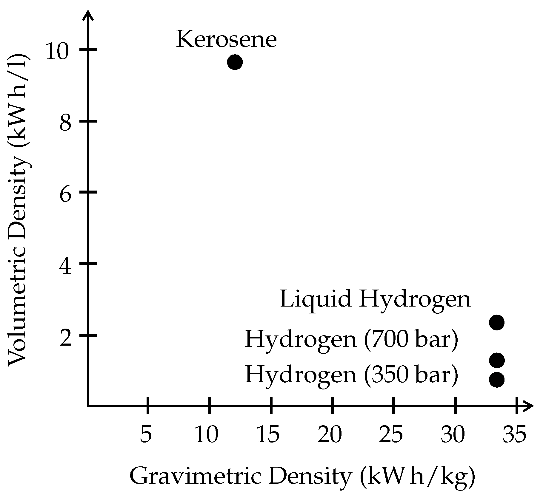
| Type of Storage | gaseous at 350 or 700 bar | liquid at 20 |
| Environmental | ||
| Temperature Range | ≈235– | ≈210– |
| Temperature Fluctuation | low | high |
| Humidity Fluctuation | low | high |
| Atmospheric Pressure | ≈1 bar | ≈0.25– bar |
| Vibrations & Shocks | existent | existent |
| Inclination | occasional | at every flight |
| Maintenance specific | ||
| Workshops | Special equipment required | Special equipment required |
| Employees | Specifically qualified | Specifically qualified |
| Goal | Road-worthiness among others | Focus on airworthiness |
| Flooding | Drying |
|---|---|
| Decrease relative humidity of inlet gases | Increase relative humidity of inlet gases |
| Increase flow of inlet gases | Decrease flow of inlet gases |
| Increase stack temperature | Decrease stack temperature |
| Decrease current | Increase current |
| Poisoning | Starvation |
| Increase air flow | Increase air flow |
| Air bleeding | Increase hydrogen flow |
| Increase pressure |
Disclaimer/Publisher’s Note: The statements, opinions and data contained in all publications are solely those of the individual author(s) and contributor(s) and not of MDPI and/or the editor(s). MDPI and/or the editor(s) disclaim responsibility for any injury to people or property resulting from any ideas, methods, instructions or products referred to in the content. |
© 2022 by the authors. Licensee MDPI, Basel, Switzerland. This article is an open access article distributed under the terms and conditions of the Creative Commons Attribution (CC BY) license (https://creativecommons.org/licenses/by/4.0/).
Share and Cite
Hoff, T.; Becker, F.; Dadashi, A.; Wicke, K.; Wende, G. Implementation of Fuel Cells in Aviation from a Maintenance, Repair and Overhaul Perspective. Aerospace 2023, 10, 23. https://doi.org/10.3390/aerospace10010023
Hoff T, Becker F, Dadashi A, Wicke K, Wende G. Implementation of Fuel Cells in Aviation from a Maintenance, Repair and Overhaul Perspective. Aerospace. 2023; 10(1):23. https://doi.org/10.3390/aerospace10010023
Chicago/Turabian StyleHoff, Tim, Florian Becker, Alireza Dadashi, Kai Wicke, and Gerko Wende. 2023. "Implementation of Fuel Cells in Aviation from a Maintenance, Repair and Overhaul Perspective" Aerospace 10, no. 1: 23. https://doi.org/10.3390/aerospace10010023