
Perception Enhancement and Improving Driving Context Recognition of an Autonomous Vehicle Using UAVs


Abstract
:1. Introduction
2. Related Works
- Radar has been an important sensor in various intelligent transportation applications [11,12]. It is known as a kind of all-weather sensor with high accuracy and long-range sensing capability [13]. It is effective in mid-to-long-range distance measurement with significant accuracy, even in poor weather [14]. It has, however, a small FOV (field of view) with poor performance in near-distance measurement and static object detection. Likewise, its reliability is affected when encountering interference from various sources, including other vehicles.
- Cameras, in both single and stereo vision, have lots of potentials. They are the least expensive sensor that can be used [10]. They can be used to (i) monitor the driver’s body posture, head position, and eye activity to detect abnormal conditions, signs of fatigue, or the vehicle behaving erratically (driving out of a straight line); and (ii) execute night-vision assistance applications to help drivers see farther down the road and detect objects such as animals, people, or trees in the path that can cause a potential risky situation or accident [15]. They require substantial computational power [16] and may have important costs when used for long-range precise detection [17]. Their performance, however, depends on the weather and brightness [14].
- LIDAR (light detection and ranging) continually fires off beams of laser light, and then measures how long it takes for the light to return to the sensor [15]. Its use in various domains has been studied since the 1980s [18], but it is only in the early 2000s that it has found its application in intelligent transportation [19,20]. It is a good tool for 3D mapping and localization with its large FOV [14]. It is dependent on good weather conditions and is less reliable outside its defined range.
- Vehicular perception in poor weather and lighting conditions;
- Vehicular perception in complex urban environments;
- Autonomous driving without heavy reliance on a priori perception data;
- Development of safety measures in case of faulty sensors/perception;
- Use of connected vehicle technology to improve accuracy, certainty, and reliability of perception.
- UAV swapping: Having many drones to use and cycling between them. When the active one is low on battery, it returns to the station to recharge and another one takes its place. This solution requires having an important swarm of drones.
- Battery hot-swapping: A single drone is used and when its battery is getting low, it returns to the station where an automatic infrastructure quickly changes its battery with a fully charged one. However, this means that the network would be lacking a node for the duration of the battery swap, and this can have some critical repercussions.
- Wireless power transfer: In 2018, Ouyang et al. submitted a model that would technically allow to power a UAV with a high-power laser. Unfortunately, this solution has not yet been tested in real conditions, and would require an almost-permanent LOS (line of sight).
3. Approach and Methodology
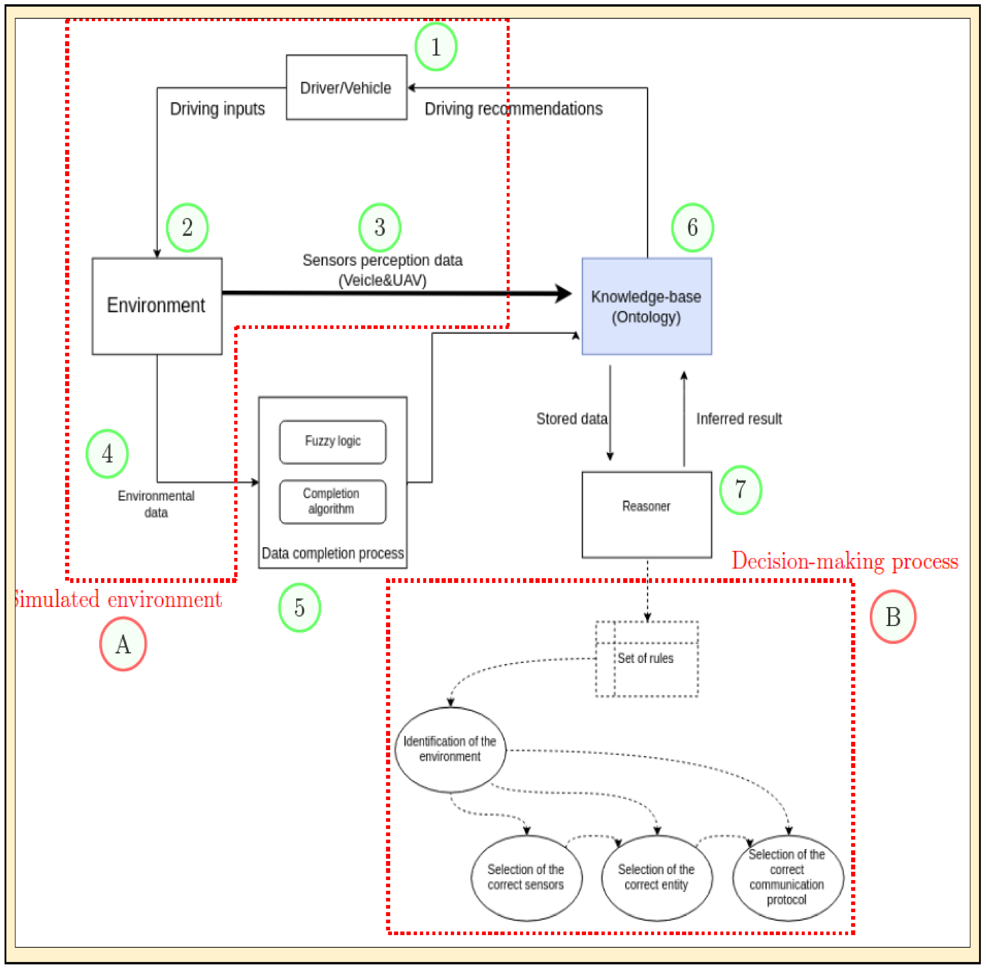
- 1.
- Our ego vehicle is on the road. The vehicle has its own sensors that perceive its environment (e.g., camera, radar, lidar, etc.). The weather, road visibility, and other hazards (e.g., rainy, slippery road, poor visibility, dark road, etc.) evolve with time.
- 2.
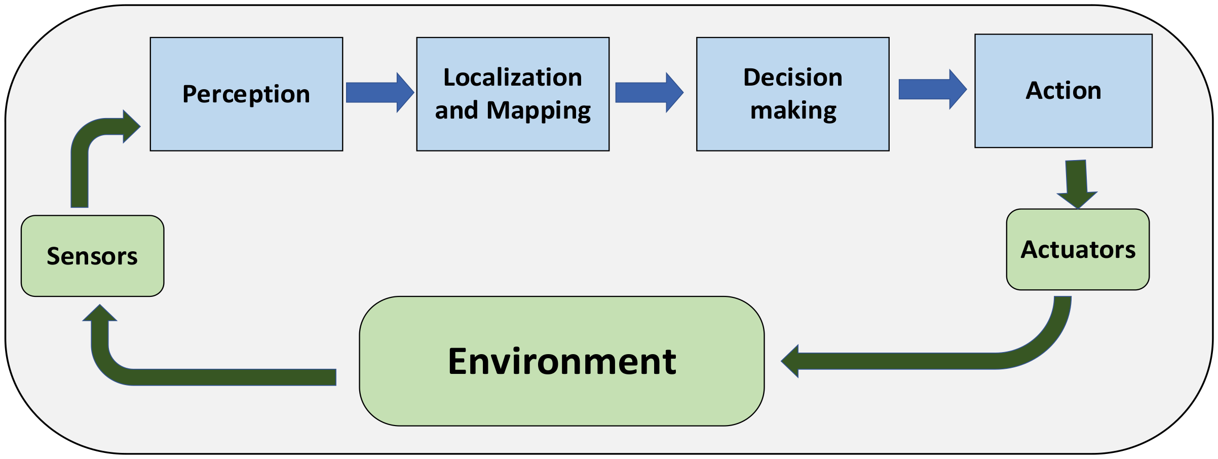
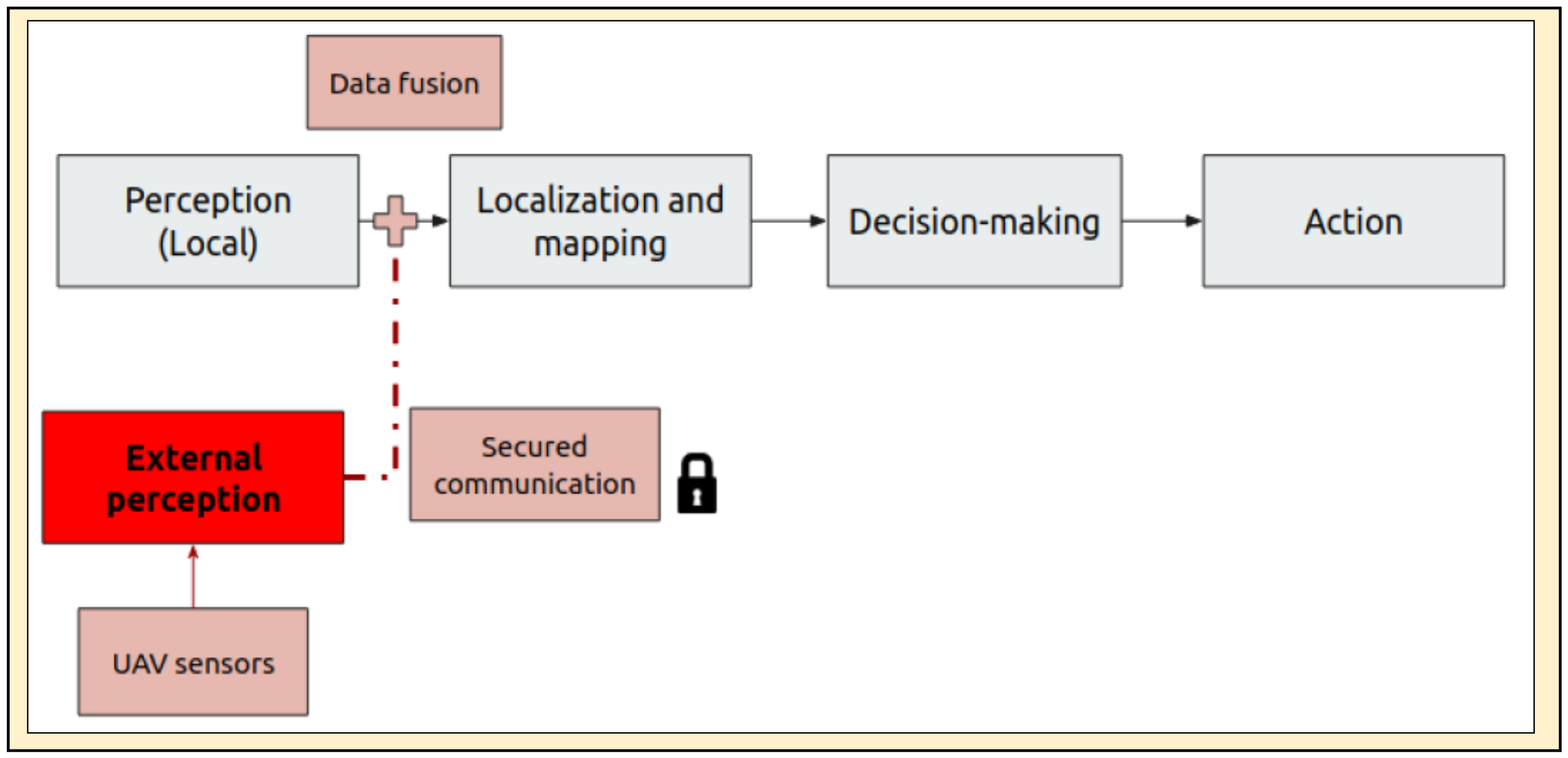
- Various sensors from the vehicle obtain data from the environment. These data reflect the actual driving situation and different entities present on the road. In Figure 2, this refers to the local perception.
- 3.
- The data taken from the environment (both local and external perceptions) are then stored in a knowledge base where they are classified and assigned corresponding properties. In ontology, the individuals of various objects instantiate the generic ontology to form an instantiated ontology.
- 4.
- Some missing data are sent to the data-completion process.
- 5.
- The data-completion process is undertaken to fill up some missing data. Fuzzy logic rules are also invoked to associate some actual values to fuzzy values (i.e., high, medium, low, etc.).
- 6.
- Data fusion is undertaken. The reasoner also cross-references the knowledge base for some objects and how they are involved to some predefined set of rules. This process identifies the logical rules that are applicable to the given situation.
- 7.
- The reasoner is the brain of the system’s decision-making process. After inferring the situation, the system also identifies the sensors and communication protocols that are appropriate for the current situation. The drones carrying the needed sensors and communication protocols are searched and their activation is requested. They are then deployed as an added layer to enhance environment perception.
- A.
- These collective processes form the simulated environment. This is the visual part that of the system. This is what is visible to the test user during the driving simulation.
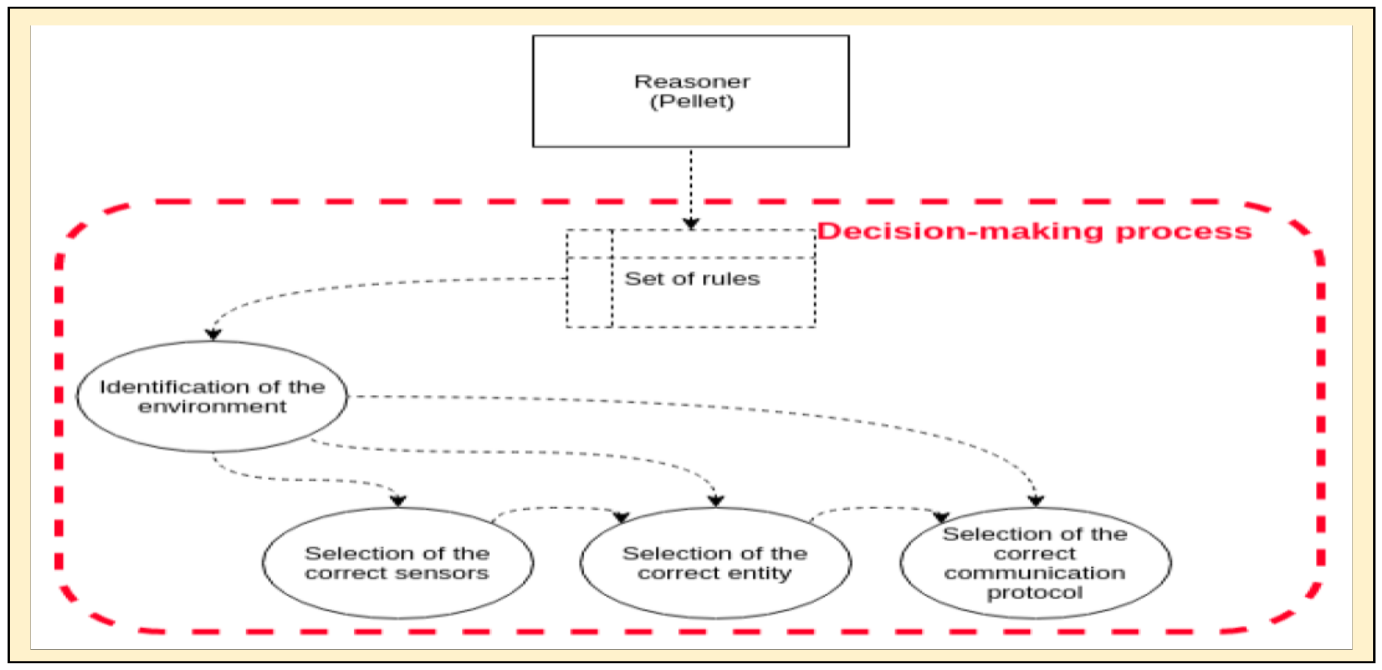
- B.
- These collective processes form the decision-making process of the system. As shown, to decide accordingly, the reasoner consults various sets of rules related to the identification of the environment, the selection of correct sensors, the selection of correct entity or UAVs that possess the correct sensors, and the selection of the correct communication protocol.
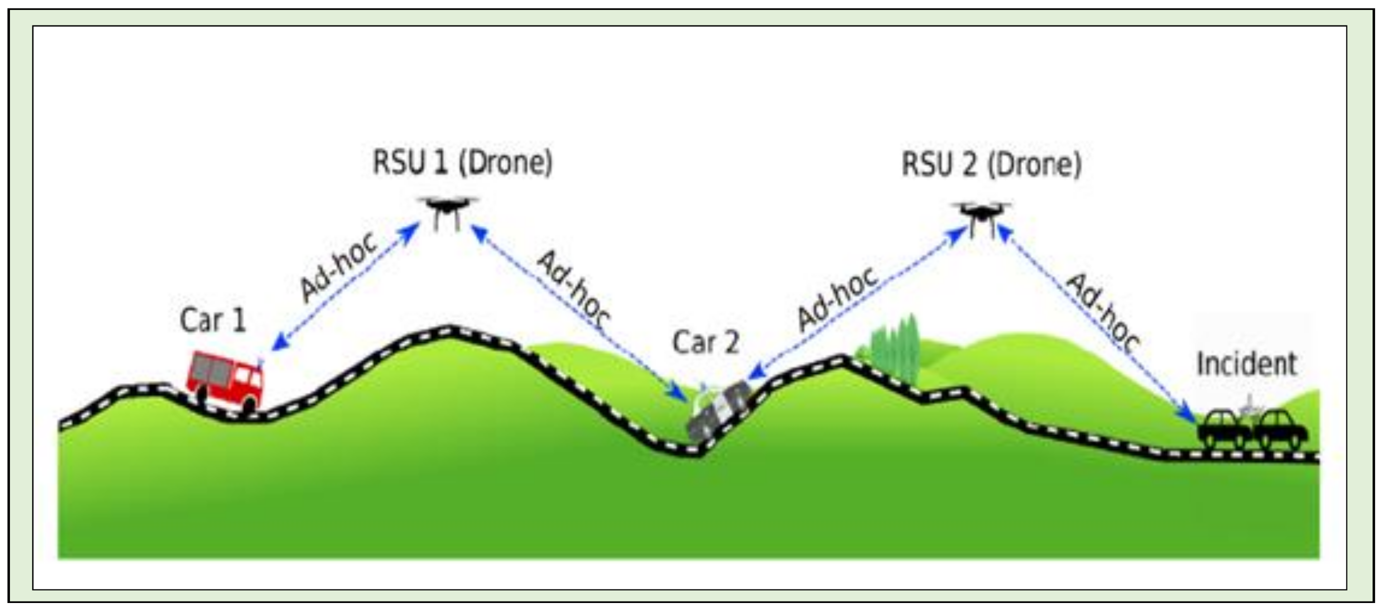
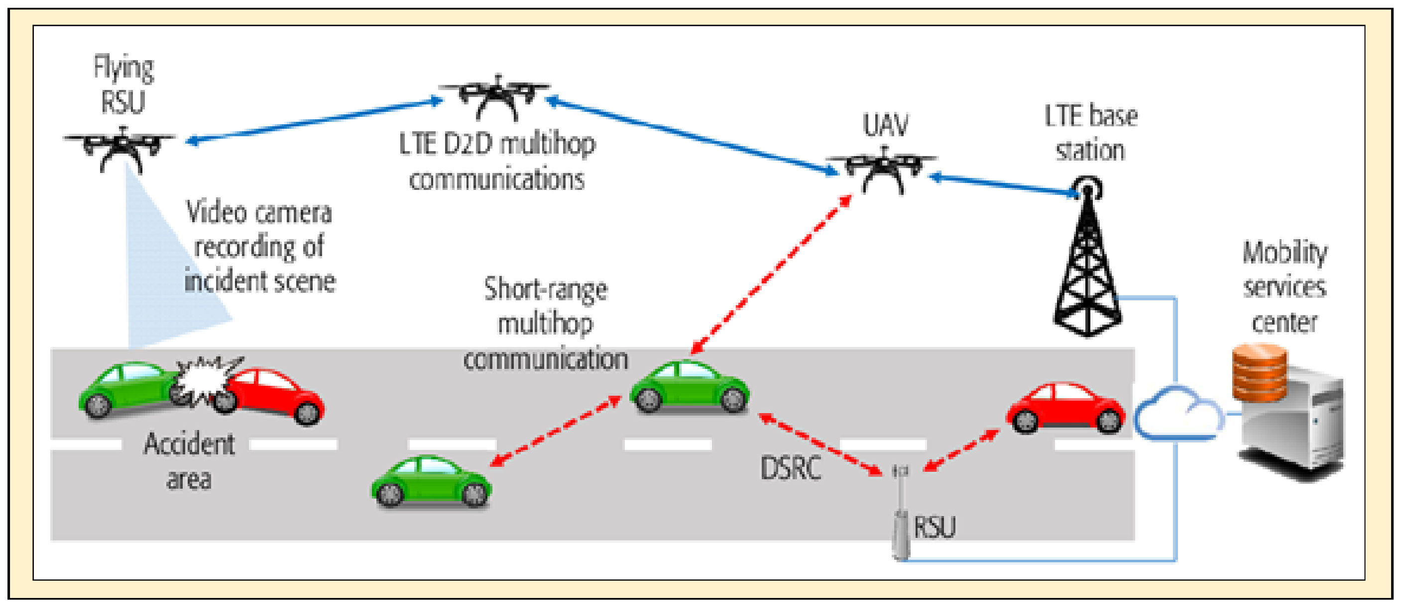
- Extension of the perception range: Given their size and positioning, UAVs can cover areas where it would normally be dangerous for the vehicle to venture in.
- Transmission integrity: By using two different physical communication protocols for redundancy, the system can make data transmission safe and robust.
- Proper context identification: Knowledge bases offer a formal way of describing an environment. When correctly populated, they can be used for an accurate recognition of the driving context.
- Rigorous management of the enhancement process: Logical rules make it possible for the reasoner to manage different actors on a scene. When fed with correct rules, the system can quickly determine which sensors and communication protocols should be activated to realize enhanced context perception.
4. Knowledge Representation and Driving Context Detection
- Scalability: Once the classes, properties, and rules are defined, the instantiation is managed by a Java API, and it is easy to populate the ontology with new elements.
- Exportability: The knowledge base and its actors are independent from the application and can be used for another operation set in a vehicular environment.
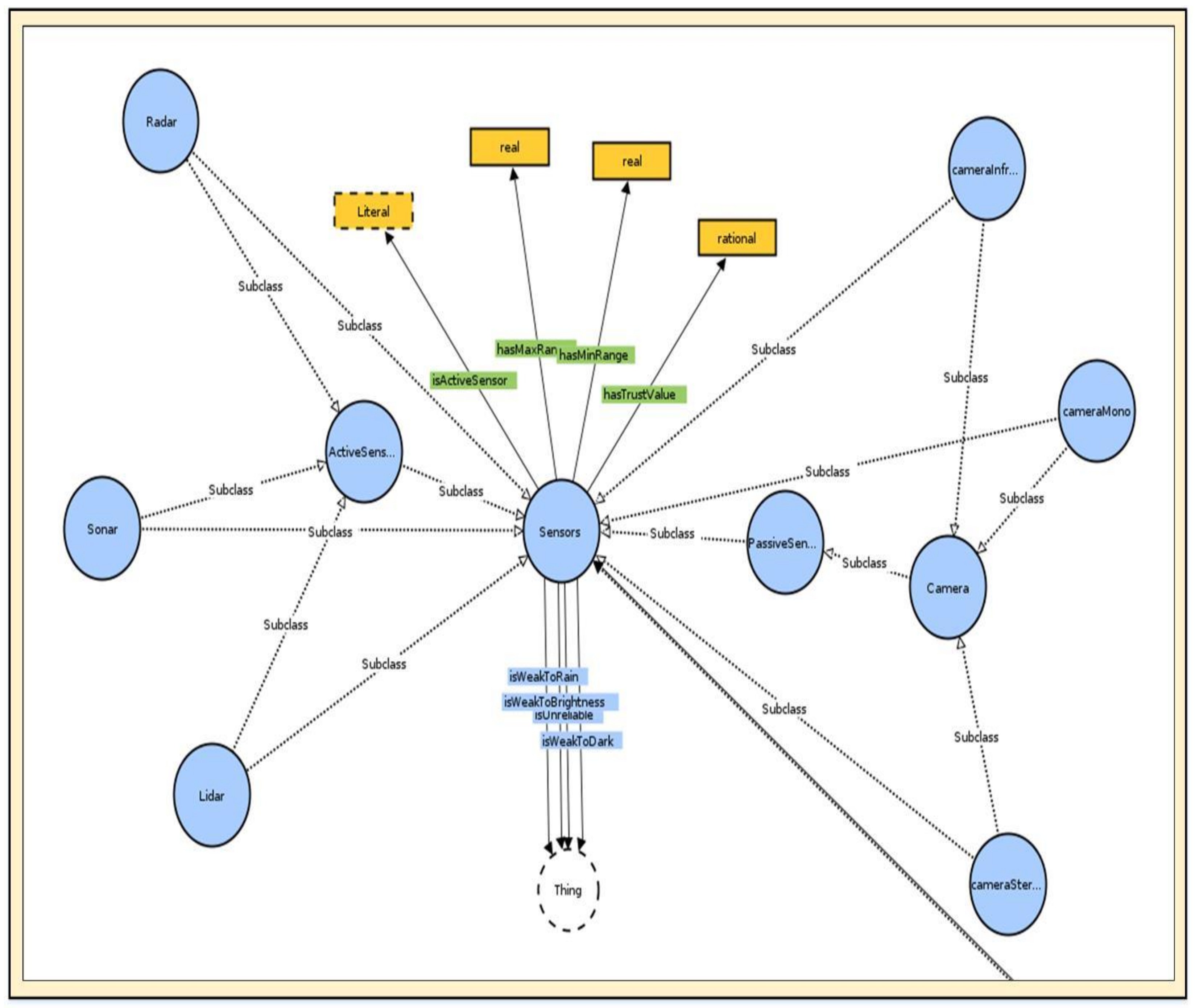
- Classes: Describe the concepts in the domain, whether they are abstract ideas or concrete entities. Classes can be hierarchized by levels, for example, having a Vehicle as a top class containing Car, Bus, and Bike as subclasses.
- Properties: The specific attributes related to a class. They can be intrinsic or extrinsic to an object, representing the interconnections between different concepts.
- Individuals: Real instances of classes, representing the elements of the ontology.
4.1. Data Fusion
4.2. Reasoning
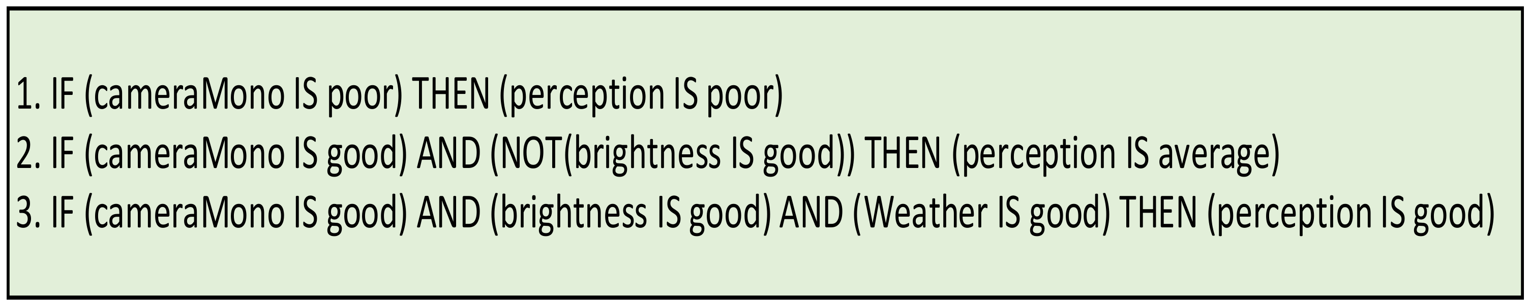
4.3. Fuzzy Logic
- Meaning representation: The first step is to translate the given propositions into a set of rigorous and usable constraints. The example given by Zadeh [51] is the following: A fuzzy approach tries to copy a human’s ability to infer based on previous experiences and social norms; thus, when we state that “usually Swedes are blond”, the term “usually” may be given an accuracy value of between 50% and 80%.
- Knowledge-based system: By definition, a knowledge base is a way to store complex structured and unstructured information, making it an “advanced” database. The storing function is then completed by an inference engine, a tool that allows the logical processing and reasoning on the stored elements. This process is enabled using an IF-THEN type of rules, which can particularly be useful when dealing with fuzzy logic.
- Defuzzification: The last part of the process is the inverse transformation that is opposite to the first one. It associates the results of the previous rules to a crisp logic equivalent value. The receiving algorithm requires a real value in order to function and relies on the defuzzification output in order to do so.
4.4. Knowledge Base Implementation
4.4.1. Sensors
- Active Sensors: Sensors that rely on their own source of emission in order to gather data. Lidars use a laser ray in order to map their surroundings. Radars generate a high-frequency electromagnetic impulse and use the Doppler effect [53] in order to calculate the distance. Ultrasound sensors rely on the same principle, but with ultrasonic waves.
- Passive Sensors: Sensors that gather data without the need for generating any form of emission. They mostly refer to cameras. There are three different types of cameras: (i) monoscopic cameras, the classical and most common ones, used for classification and image processing; (ii) stereoscopic cameras, which rely on the same principle except with more cameras, allowing for depth perception; and (iii) thermal cameras, cameras using infrared radiation, which allow for their use in bad weather and poorly illuminated environments but make the detection and classification of elements harder.
- Environmental Sensors: Sensors used for the detection of environmental variables, including rain, fog, and brightness.
- isWeakToRain property means that the sensor performs poorly in the case of rain;
- isWeakToFog property means that the sensor performs poorly in the case of fog;
- isWeakToBrightness property means that the sensor performs poorly in the case of overbrightness;
- isWeakToDark property means that the sensor performs poorly in the case of lack of illumination;
- isUnreliable property means that the sensor performs poorly due to some reasons;
- hasMinRange property represents the minimal functioning range of a sensor;
- hasMaxRange property represents the maximal functioning range of a sensor;
- isActiveSensor property defines if a sensor should be activated or not depending on the environmental situation.
4.4.2. Vehicle
- hasDriver is a functional property between a vehicle and a driver. It allows for the identification of the ego vehicle, which will contain the main driver individual.
- hasSensor is a property that associates a vehicle with all the sensors embedded on it.
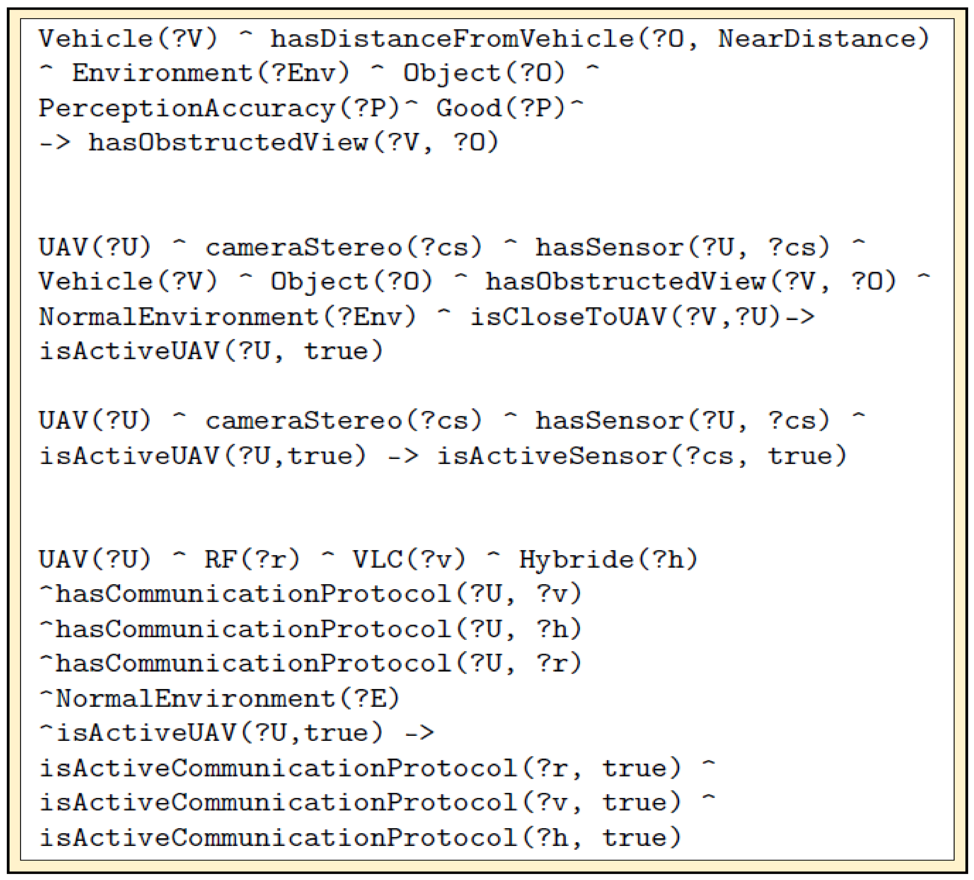
- hasDistanceFromVehicle is a property that allows for the fuzzy classification of the distance between a vehicle and a physical obstacle on the road. It can have a value of “Far”, “Medium”, or “Close”. It can be associated with the Boolean data property that has obstructed view.
- isCloseToUAV applies when the ego vehicle is within the communication reach of a UAV. If the conditions are met, it can be associated with the Boolean data property that is active UAV for the data-gathering request.
4.4.3. Communication Protocol
4.4.4. Logical Rules
4.4.5. Environmental Detection
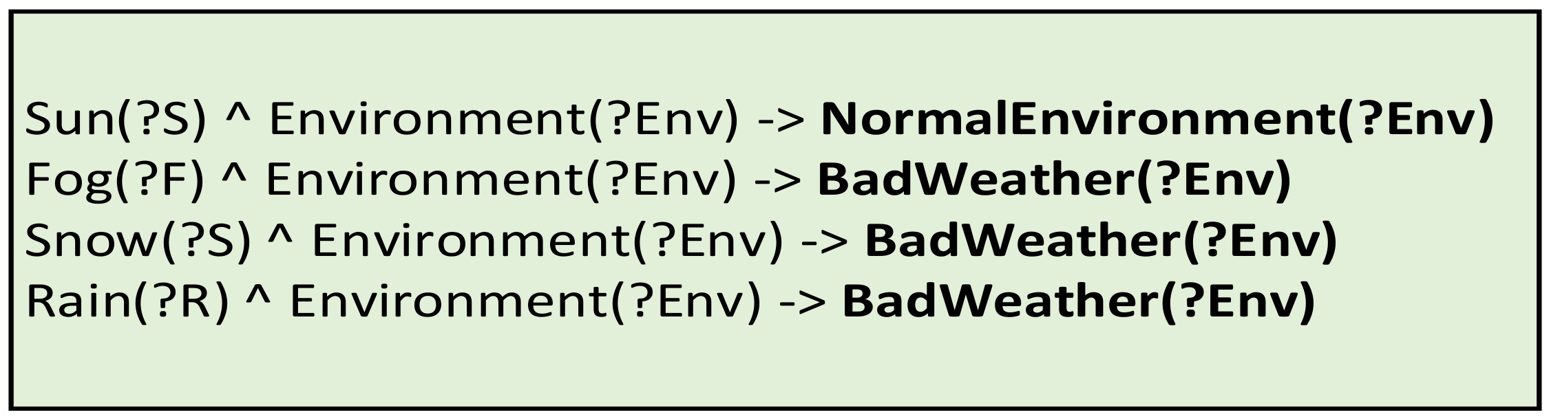
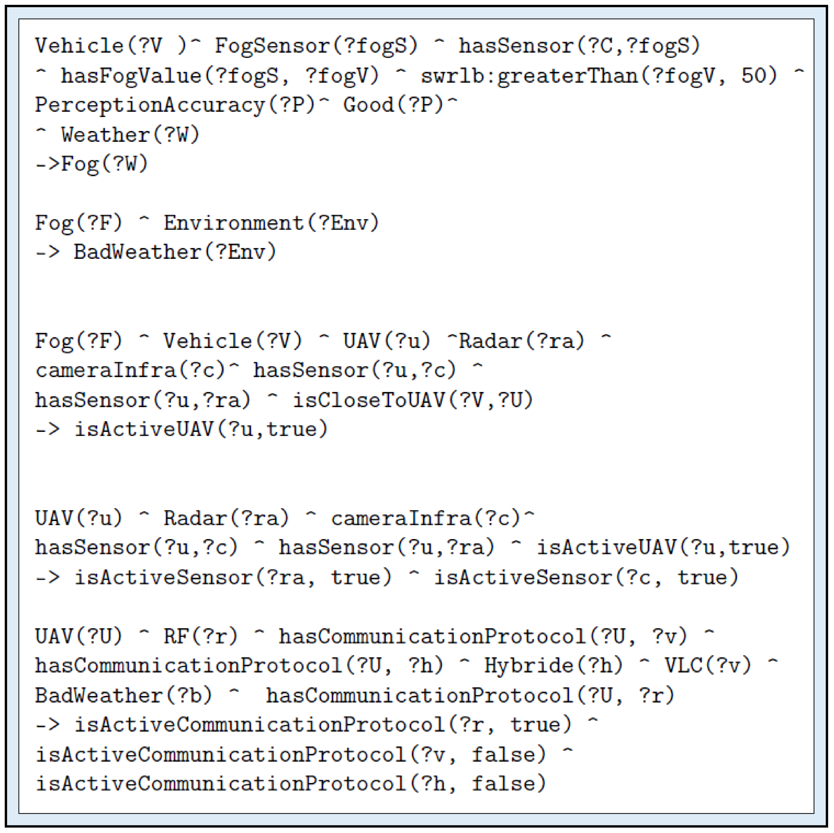
- The environmental sensors gather the value of an environment variable and compare it to a threshold IF (envSensor exists for environment X) AND (envSensor returns envValue) AND (envValue bigger than threshold value) THEN (environment is of type X).
- In the case that different contexts can be linked to a single environment (for example, a rainy or foggy context both correspond to a bad weather situation), then this can also be simplified by using logical rules IF (environment is Rain) THEN (environment is BadWeather); IF (environment is Fog) THEN (environment is BadWeather).
- Some other situations can be covered, for example, limited visibility IF (object on the road) AND (vehicle on the road) AND (object is very close to the vehicle) THEN (the view is obstructed) or a fire hazard event IF (vehicle on the road) AND (building nearby) AND (building is on fire) THEN (there is a hazard of type FireHazard) AND (environment is of UnusualEnvironment type).
4.4.6. Entity, Sensors, and Communication Protocols Management
- When a UAV is identified, there is a need to check if it contains the correct sensors: IF (there is a vehicle) AND (there is a UAV) AND (there is an environment of type X) AND (there are sensors appropriate for that specific environment) AND (the UAV is carrying the sensors) AND (the UAV is close enough to the vehicle) THEN (the UAV is activated). Activating a UAV in the knowledge base means requesting perception data from it.
- Once activated, there is also a need to activate the needed sensors: IF (there is a UAV) AND (there are sensors working on that specific environment) AND (the UAV is carrying the sensors) AND (the UAV is active) THEN (activate the sensors on the UAV).
- The same methodology is applied to the communication protocol: IF (there is an environment of type X) AND (there are communication protocols appropriate for environment X) AND (there is a UAV) AND (the UAV can communicate using the defined protocols) THEN (activate the communication protocols).
4.5. Decision-Making Process
4.5.1. Detection of Environment with Respect to Weather and Other Hindrances
4.5.2. Entity and Sensor Activation
4.5.3. Summary of the Process
- Environment detection with respect to weather and other hazards: The system infers what kind of environment the vehicle is advancing in;
- Sensor activation: The system decides what sensors are most appropriate in the current environment;
- Entity activation: The system looks up nearby entities (UAVs) carrying the appropriate sensors;
- Communication protocol activation: The system selects the appropriate communication protocol based on the context of the environment.
- The knowledge base also contains a list of different entities (UAV) available on site and their embedded sensors, allowing for the system to select which ones should be requested.
- The same knowledge base also includes different communication protocols available on each entity, as well as their respective weaknesses. The logical rules were implemented by taking into consideration all these elements and allowing the reasoner to output different inferred elements: the current environment, requesting assistance on a specific entity, activation on specific sensors, activation of specific communication protocols, and if possible, driving recommendations.
5. Tests and Validation
5.1. The Simulator
- The data generator component manages the virtual data that will be generated and gathered by the system. There are three different types of data:
- o
- Driving data, related to the ego vehicle and controlled by the subject and influenced by the driving environment. All these data are directly influenced by the subject driver. Example: speed, direction of the steering angle, etc.
- o
- Environmental data are data that are captured by the Environment sensors. The simulator allows for the manipulation of different variables, for example, brightness or rain level, and those can be used for the correct identification of the environment.
- o
- Perception data are those gathered by other perception sensors, such as the distance or position of sensors. They are generated by the sensors embedded on the vehicles and UAV, and are used for the identification of other entities on the road.
- The knowledge base interface component manages the interface of the simulated environment and the knowledge base. The generated data are encapsulated in JSON format before being sent to the knowledge base via a TCP socket, and the same channel is used to receive the inference results and driving recommendation.
- The HMI (human–machine interface) component allows for the interaction between the user and the simulator. The actions that the driver takes are shown in the simulator, such as the car moving when the driver uses the accelerator; and the assistance widget displays the results of the inference engine, for example, a warning of the presence of an obstacle ahead.
5.2. Knowledge Base
5.3. Notification Assistance
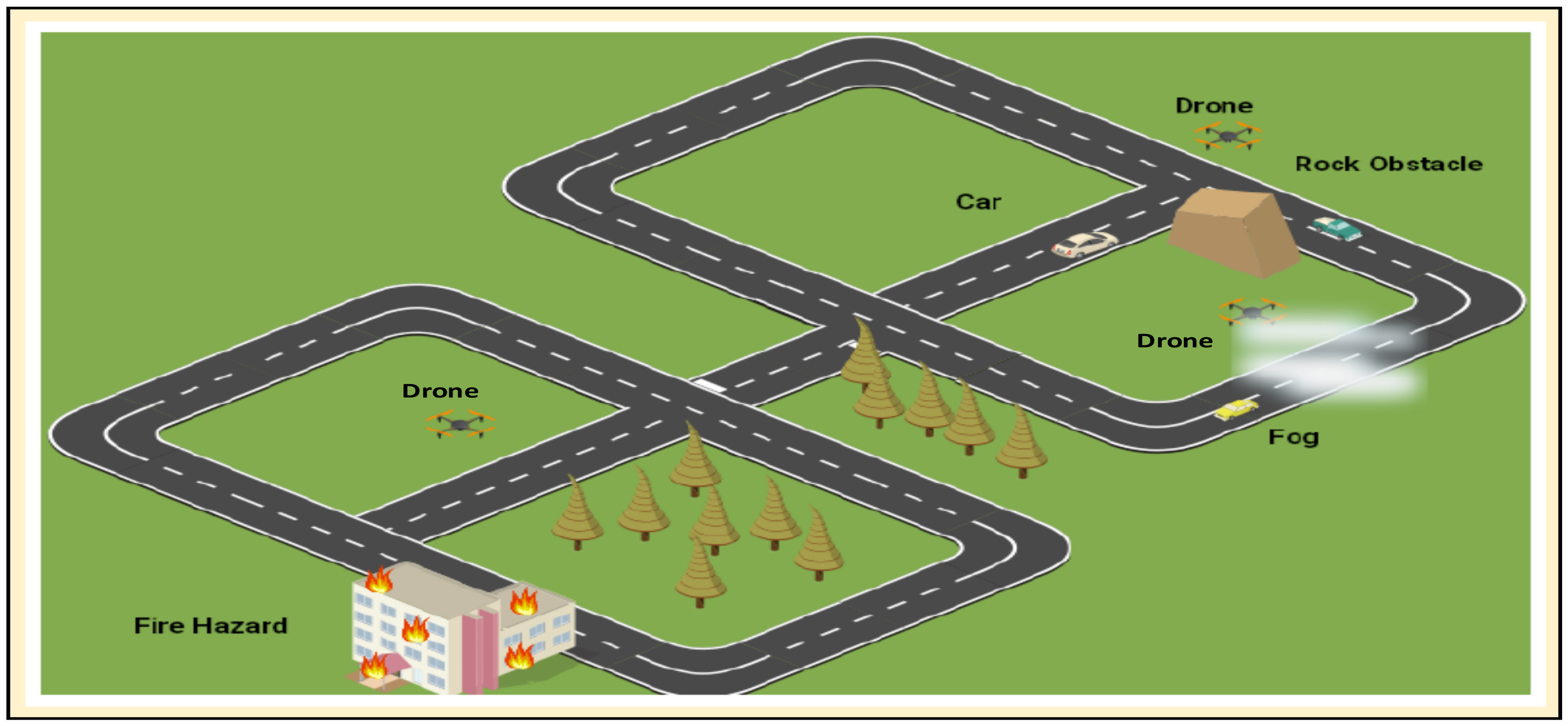
5.4. Use Case Scenarios
- The first scenario involves an ego vehicle, going into an intersection with an obstructed view;
- The second scenario involves a rainy environment;
- The third scenario is a foggy environment where visibility is poor. The drone is available to provide added environment perception data;
- The fourth scenario involves driving in a poorly lit environment where the whole area is dark;
- The last scenario is a complex one with an obstructed view, foggy area, and fire hazard present, which the test subject needs to pass.
6. Results and Discussion
- Drivers are fully assisted when UAVs with both appropriate sensors and communication protocols are present. The assistance is rendered in the form of advanced driving notification (e.g., obstacle or danger that lies ahead).
- Drivers are only partially assisted when either the appropriate sensors or communication protocols are missing. Drivers are not assisted and on their own whenever both appropriate sensors and communication protocols are absent in the UAVs; hence, the UAVs cannot be used as extra tools to enhance driving context perception.
- When drivers are fully assisted, the time for the pilot to complete the test circuit in the experiment is faster. Their average and maximum vehicular speeds improve significantly.
- Drivers that are not or only partially assisted finished the test circuit longer. Their speeds are slower and incidents are higher.
- The subjects drive faster when they already know some events coming ahead of time due to full notification assistance.
- There is minimal incident among the drivers when they have full notification assistance.
7. Conclusions and Future Work
- A new application of UAVs, that is, to equip them with necessary sensors and communication protocols so that they can be used to supply external perception to an autonomous vehicle;
- Knowledge representation using ontology and a functional knowledge base, and a set of logical rules for context detection and perception enhancement;
- A hybrid VLC/RF communication protocol for safer transmission;
- A driving simulator with a realistic physics engine for testing scenarios.
Author Contributions
Funding
Institutional Review Board Statement
Informed Consent Statement
Data Availability Statement
Conflicts of Interest
References
- Wikipedia. List of Countries by Vehicles per Capita. Available online: https://en.wikipedia.org/ (accessed on 1 June 2022).
- Fayyad, J.; Jaradat, M.A.; Gruyer, D.; Najjaran, H. Deep Learning Sensor Fusion for Autonomous Vehicle Perception and Localization: A Review. Sensors 2020, 20, 4220. [Google Scholar] [CrossRef] [PubMed]
- Zheng, R.; Liu, C.; Guo, Q. A decision-making method for autonomous vehicles based on simulation and reinforcement learning. In Proceedings of the International Conference on Machine Learning and Cybernetics, Tianjin, China, 14–17 July 2013. [Google Scholar]
- Khezaz, A.; Hina, M.D.; Guan, H.; Ramdane-Cherif, A. Knowledge-Based Approach for the Perception Enhancement of a Vehicle. J. Sens. Actuator Netw. 2021, 10, 66. [Google Scholar] [CrossRef]
- Das, S.; Brimley, B.K.; Lindheimer, T.E.; Zupancich, M. Association of reduced visibility with crash outcomes. IATSS Res. 2018, 42, 143–151. [Google Scholar] [CrossRef]
- WHO (World Health Organization). 10 Facts on Global Road Safety. Available online: http://www.who.int/features/factfiles/roadsafety/en/ (accessed on 20 January 2022).
- WHO (World Health Organization). Save LIVES: A Road Safety Technical Package. 2017. Available online: https://www.who.int/publications/i/item/save-lives-a-road-safety-technical-package (accessed on 1 June 2022).
- Van Brummelen, J.; O’Brien, M.; Gruyer, D.; Najjaran, H. Autonomous vehicle perception: The technology of today and tomorrow. Transp. Res. Part C Emerg. Technol. 2018, 89, 384–406. [Google Scholar] [CrossRef]
- Campbell, M.; Egerstedt, M.; How, J.P.; Murray, R.M. Autonomous driving in urban environments: Approaches, lessons and challenge. Philos. Trans. R. Soc. A Math. Phys. Eng. Sci. 2010, 368, 4649–4672. [Google Scholar] [CrossRef]
- Vanholme, B.; Gruyer, D.; Lusetti, B.; Glaser, S.; Mammar, S. Highly Automated Driving on Highways Based on Legal Safety. IEEE Trans. Intell. Transp. Syst. 2012, 14, 333–347. [Google Scholar] [CrossRef]
- Zyda, M. Creating a Science of Games: Introduction. Commun. ACM Spec. Issue Creat. A Sci. Games 2007, 50, 26–29. [Google Scholar]
- Mayhan, R.J.; Bishel, R.A. A two-frequency radar for vehicle automatic lateral control. IEEE Trans. Veh. Technol. 1982, 31, 32–39. [Google Scholar] [CrossRef]
- Du, Y.; Man, K.L.; Lim, E.G. Image Radar-based Traffic Surveillance System: An all-weather sensor as intelligent transportation infrastructure component. In Proceedings of the 2020 International SoC Design Conference (ISOCC), Yeosu, Korea, 21–24 October 2020. [Google Scholar]
- Rasshofer, R.H.; Gresser, K. Automotive Radar and Lidar Systems for Next Generation Driver Assistance Functions. Adv. Radio Sci. 2005, 3, 205–209. [Google Scholar] [CrossRef]
- Guerrero-Ibáñez, J.; Zeadally, S.; Contreras-Castillo, J. Sensor Technologies for Intelligent Transportation Systems. Sensors 2018, 18, 1212. [Google Scholar] [CrossRef]
- Sivaraman, S.; Trivedi, M.M. Looking at Vehicles on the Road: A Survey of Vision-Based Vehicle Detection, Tracking, and Behavior Analysis. IEEE Trans. Intell. Transp. Syst. 2013, 14, 1773–1795. [Google Scholar] [CrossRef] [Green Version]
- Sahin, F. Long-Range, High-Resolution Camera Optical Design for Assisted and Autonomous Driving. Photonics 2019, 6, 73. [Google Scholar] [CrossRef]
- Smith, M. Light Detection and Ranging (LIDAR); Volume 2, A Bibliography with Abstracts, Progress Report, 1975; National Technical Information Service: Springfield, VA, USA, 1978. [Google Scholar]
- Li, B.; Zhang, T.; Xia, T. Vehicle Detection from 3D Lidar Using Fully Convolutional Network. arXiv 2016, arXiv:1608.07916. [Google Scholar]
- Mahlisch, M.; Schweiger, R.; Ritter, W.; Dietmayer, K. Sensor fusion Using Spatio-Temporal Aligned Video and Lidar for Improved Vehicle Detection. In Proceedings of the IEEE Intelligent Vehicles Symposium, Meguro-Ku, Japan, 13–15 June 2006. [Google Scholar]
- Ghazzai, H.; Menouar, H.; Kadri, A. On the Placement of UAV Docking Stations for Future Intelligent Transportation Systems. In Proceedings of the IEEE 85th Vehicular Technology Conference, Sydney, NSW, Australia, 4–7 June 2017. [Google Scholar]
- Starship Technologies. Starship. Available online: https://www.starship.xyz (accessed on 15 January 2022).
- Google. Google X Wing. Available online: https://wing.com/ (accessed on 15 January 2022).
- Amazon. Amazon Prime Air. Available online: www.amazon.com/primeair (accessed on 12 March 2022).
- Sakiyama, M. The Balance between Privacy and Safety in Police UAV Use: The Power of Treat and Its Effect on People’s Receptivity. Ph.D. Thesis, University of Nevada, Reno, NV, USA, 2017. [Google Scholar]
- Xu, Y.; Yu, G.; Wang, Y.; Wu, X.; Ma, Y. Car Detection from Low-Altitude UAV Imagery with the Faster R-CNN. J. Adv. Transp. 2017, 2017, 1–10. [Google Scholar] [CrossRef]
- Hadiwardoyo, S.A.; Hernández-Orallo, E.; Calafate, C.T.; Cano, J.C.; Manzoni, P. Experimental characterization of UAV-to-car communications. Comput. Netw. 2018, 136, 105–118. [Google Scholar] [CrossRef]
- Menouar, H.; Guvenc, I.; Akkaya, K.; Uluagac, A.S.; Kadri, A.; Tuncer, A. UAV-Enabled Intelligent Transportation Systems for the Smart City: Applications and Challenges. IEEE Commun. Mag. 2017, 55, 22–28. [Google Scholar] [CrossRef]
- Shi, W.E.A. Drone Assisted Vehicular Networks: Architecture, Challenges and Opportunities. IEEE Netw. 2018, 32, 130–137. [Google Scholar] [CrossRef]
- Galkin, B.; Kibilda, J.; DaSilva, L.A. UAVs as Mobile Infrastructure: Addressing Battery Lifetime. IEEE Commun. Mag. 2019, 57, 132–137. [Google Scholar] [CrossRef]
- Grimm, S.; Hitzler, P.; Abecker, A. Knowledge Representation and Ontologies. In Semantic Web Services: Concepts, Technology and Applications; Studer, R., Grimm, S., Abecker, A., Eds.; Springer: Berlin, Germany, 2007; pp. 51–106. [Google Scholar]
- Guarino, N. Formal ontology, conceptual analysis and knowledge representation. Int. J. Hum.-Comput. Stud. 1995, 43, 625–640. [Google Scholar] [CrossRef]
- O’Keefe, R.M.; Balci, O.; Smith, E.P. Validation of Expert System Performance; Virginia Polytechnic Institute & State University: Blacksburg, VA, USA, 1987; Volume 2. [Google Scholar]
- Jaffar, J.; Maher, M.J. Constraint logic programming: A survey. J. Log. Program. 1994, 19–20, 503–581. [Google Scholar] [CrossRef]
- Paulheim, H. Knowledge graph refinement: A survey of approaches and evaluation methods. Semant. Web 2016, 8, 489–508. [Google Scholar] [CrossRef]
- Noy, N.F.; McGuinness, D.L. Ontology Development 101: A Guide to Creating Your First Ontology. Available online: http://protege.stanford.edu/publications/ontology_development/ontology101-noy-mcguinness.html (accessed on 5 July 2017).
- Horridge, M.; Bechhofer, S. The OWL API: A Java API for OWL ontologies. Semant. Web 2011, 2, 11–21. [Google Scholar] [CrossRef]
- Regele, R. Using Ontology-Based Traffic Models for More Efficient Decision Making of Autonomous Vehicles. In Proceedings of the 4th International Conference on Autonomic and Autonomous Systems (ICAS’08), Gosier, France, 16–21 March 2008. [Google Scholar]
- Maalel, A.; Mabrouk, H.H.; Mejri, L.; Ghezela, H.H.B. Development of an ontology to assist the modeling of accident scenario application on railroad transport. J. Comput. 2011, 3, 1–7. [Google Scholar]
- Hulsen, M.; Zollner, J.M.; Weiss, C. Traffic Intersection Situation Description Ontology for Advanced Driver Assistance. In Proceedings of the IEEE Intelligent Vehicles Symposium, 2011 IEEE Intelligent Vehicles Symposium, Baden, Germany, 5–9 June 2011. [Google Scholar]
- Lahat, D.; Adali, T.; Jutten, C. Multimodal data fusion: An overview of methods, challenges, and prospects. Proc. IEEE 2015, 103, 1449–1477. [Google Scholar] [CrossRef]
- Llinas, J.; Hall, D. An introduction to multisensor data fusion. Proc. IEEE 1997, 85, 6–23. [Google Scholar]
- Hina, M.D.; Thierry, C.; Soukane, A.; Ramdane-Cherif, A. Cognition of Driving Context for Driving Assistance. Int. J. Comput. Inf. Eng. 2018, 12, 56–66. [Google Scholar]
- Bobzien, S. (Ed.) The Stanford Encyclopedia of Philosophy Metaphysics Research Lab; Stanford University: Stanford, CA, USA, 2020. [Google Scholar]
- W3C. SWRL: A Semantic Web Rule Language Combining OWL and RuleML. Available online: https://www.w3.org/Submission/SWRL/ (accessed on 15 January 2022).
- O’Connor, M.; ShankarMark, R.V.; Musen, M.A.; Das, A.; Nyulas, C. The SWRLAPI: A Development Environment for Working with SWRL Rules. In Proceedings of the Fifth OWLED Workshop on OWL: Experiences and Directions, Karlsruhe, Germany, 26–27 October 2008. [Google Scholar]
- Liu, C.-H.; Chang, K.-L.; Chen, J.; Hung, S.-C. Ontology-Based Context Representation and Reasoning Using OWL and SWRL. In Proceedings of the 8th Annual Communication Networks and Services Research Conference, Montreal, QC, Canada, 11–14 May 2010. [Google Scholar]
- Mir, A.; Hassan, A. Fuzzy Inference Rule-based Neural Traffic Light Controller. In Proceedings of the IEEE International Conference on Mechatronics and Automation, Changchun, China, 5–8 August 2018. [Google Scholar]
- Fernandez, S.; Ito, T. Driver Classification for Intelligent Transportation Systems Using Fuzzy Logic. In Proceedings of the ITSC 2016, IEEE International Conference on Intelligent Transportation Systems, Rio de Janeiro, Brazil, 1–4 November 2016. [Google Scholar]
- Azim, T.; Jaffar, M.A.; Mirza, A.M. Fully automated real time fatigue detection of drivers through fuzzy expert systems. Appl. Soft Comput. 2014, 18, 25–38. [Google Scholar] [CrossRef]
- Zadeh, L.A. Is there a need for fuzzy logic? Inf. Sci. 2008, 178, 2751–2779. [Google Scholar] [CrossRef]
- Khezaz, A.; Hina, M.D.; Guan, H.; Ramdane-Cherif, A. Hybrid Machine Learning Model for Traffic Forecasting. Lect. Notes Inst. Comput. Sci. Soc. Inform. Telecommun. Eng. 2021, 372, 188–199. [Google Scholar]
- Chen, V.C.; Li, F.; Ho, S.-S.; Wechsler, H. Micro-Doppler effect in radar: Phenomenon, model, and simulation study. IEEE Trans. Aerosp. Electron. Syst. 2006, 42, 2–21. [Google Scholar] [CrossRef]
- Protégé. Protégé: Open-Source Ontology Editor. Available online: http://protege.stanford.edu (accessed on 15 June 2021).
- Thalen, J.P. ADAS for the Car of the Future; University of Twente: Enschede, The Netherlands, 2006. [Google Scholar]
- Li, L.; Wen, D.; Zheng, N.-N.; Shen, L.-C. Cognitive Cars: A New Frontier for ADAS Research. IEEE Trans. Intell. Transp. Syst. 2012, 13, 395–407. [Google Scholar] [CrossRef]
- Hina, M.D.; Guan, H.; Soukane, A.; Ramdane-Cherif, A. CASA: An Alternative Smartphone-Based ADAS. Int. J. Inf. Technol. Decis. Mak. 2021, 21, 273–313. [Google Scholar] [CrossRef]
- Shinzato, P.Y.; Wolf, D.F.; Stiller, C. Road terrain detection: Avoiding common obstacle detection assumptions using sensor fusion. In Proceedings of the 2014 IEEE Intelligent Vehicles Symposium Proceedings, Dearborn, MI, USA, 8–11 June 2014; pp. 687–692. [Google Scholar]
- Ithape, A.A. Artificial Intelligence and Machine Learning in ADAS. In Proceedings of the Vector India Conference, Pune, India, 18–19 July 2017. [Google Scholar]
- Hina, M.D.; Thierry, C.; Soukane, A.; Ramdane-Cherif, A. Ontological and Machine Learning Approaches for Managing Driving Context in Intelligent Transportation. In Proceedings of the KEOD 2017, 9th International Conference on Knowledge Engineering and Ontology Development, Madeira, Portugal, 1–3 November 2017. [Google Scholar]
- Jahangiri, A.; Rakha, H.A. Applying Machine Learning Techniques to Transportation Mode Recognition Using Mobile Phone Sensor Data. IEEE Trans. Intell. Transp. Syst. 2015, 16, 2406–2417. [Google Scholar] [CrossRef]


| Category | Sensor Type | Application and Use |
|---|---|---|
| Intrusive | Pneumatic road tube | Used for keeping track of the number of vehicles, vehicle classification and vehicle count. |
| Inductive loop detector (ILD) | Used for detection of vehicle movement, presence, count and occupancy. The signals generated are recorded in a device at the roadside. | |
| Magnetic sensors | Used for detection of presence of vehicle, identifying stopped and moving vehicles. | |
| Piezoelectric | Classification of vehicles, counting vehicles, and measuring vehicle weight and speed. | |
| Nonintrusive | Video cameras | Detection of vehicles across several lanes; can classify vehicles by their length and report vehicle presence, flow rate, occupancy, and speed for each class. |
| Radar sensors | Vehicular volume and speed measurement, detection of direction of motion of vehicle; used by applications for managing traffic lights. | |
| Infrared | Application for speed measurement, vehicle length, volume, and lane occupancy. | |
| Ultrasonic | Tracking the number of vehicles, vehicle presence, and occupancy. | |
| Acoustic array sensors | Used in the development of applications for measuring vehicle passage, presence, and speed. | |
| Road surface condition sensors | Used to collect information on weather conditions such as the surface temperature, dew point, water film height, the road conditions, and grip. | |
| RFID (Radio-frequency identification) | Used to track vehicles mainly for toll management. |
Publisher’s Note: MDPI stays neutral with regard to jurisdictional claims in published maps and institutional affiliations. |
© 2022 by the authors. Licensee MDPI, Basel, Switzerland. This article is an open access article distributed under the terms and conditions of the Creative Commons Attribution (CC BY) license (https://creativecommons.org/licenses/by/4.0/).
Share and Cite
Khezaz, A.; Hina, M.D.; Ramdane-Cherif, A. Perception Enhancement and Improving Driving Context Recognition of an Autonomous Vehicle Using UAVs. J. Sens. Actuator Netw. 2022, 11, 56. https://doi.org/10.3390/jsan11040056
Khezaz A, Hina MD, Ramdane-Cherif A. Perception Enhancement and Improving Driving Context Recognition of an Autonomous Vehicle Using UAVs. Journal of Sensor and Actuator Networks. 2022; 11(4):56. https://doi.org/10.3390/jsan11040056
Chicago/Turabian StyleKhezaz, Abderraouf, Manolo Dulva Hina, and Amar Ramdane-Cherif. 2022. "Perception Enhancement and Improving Driving Context Recognition of an Autonomous Vehicle Using UAVs" Journal of Sensor and Actuator Networks 11, no. 4: 56. https://doi.org/10.3390/jsan11040056