A Review of the Literature on the Lower-Mobility Parallel Manipulators of 3-UPU or 3-URU Type


Department of Engineering, University of Ferrara, 44122 Ferrara, Italy
Robotics 2020, 9(1), 5; https://doi.org/10.3390/robotics9010005
Submission received: 10 December 2019
/
Revised: 28 December 2019
/
Accepted: 10 January 2020
/
Published: 13 January 2020
(This article belongs to the Special Issue Kinematics and Robot Design II, KaRD2019)
Abstract
:Various 3-UPU architectures feature two rigid bodies connected to one another through three kinematic chains (limbs) of universal–prismatic–universal (UPU) type. They were first proposed in the last decade of the 20th century and have animated discussions among researchers for more-or-less two decades. Such discussions brought to light many features of lower-mobility parallel manipulators (PMs) that were unknown until then. The discussions also showed that such architectures may be sized into translational PMs, parallel wrists, or even reconfigurable (metamorphic) PMs. Even though commercial robots with these architectures have not yet been built, the interest in them remains. Consequently, a review of the literature on these architectures, highlighting their contribution to the progress of lower-mobility PM design, is still of interest for the scientific community. This paper aims at presenting a critical review of the results that have been obtained up until now.
1. Introduction
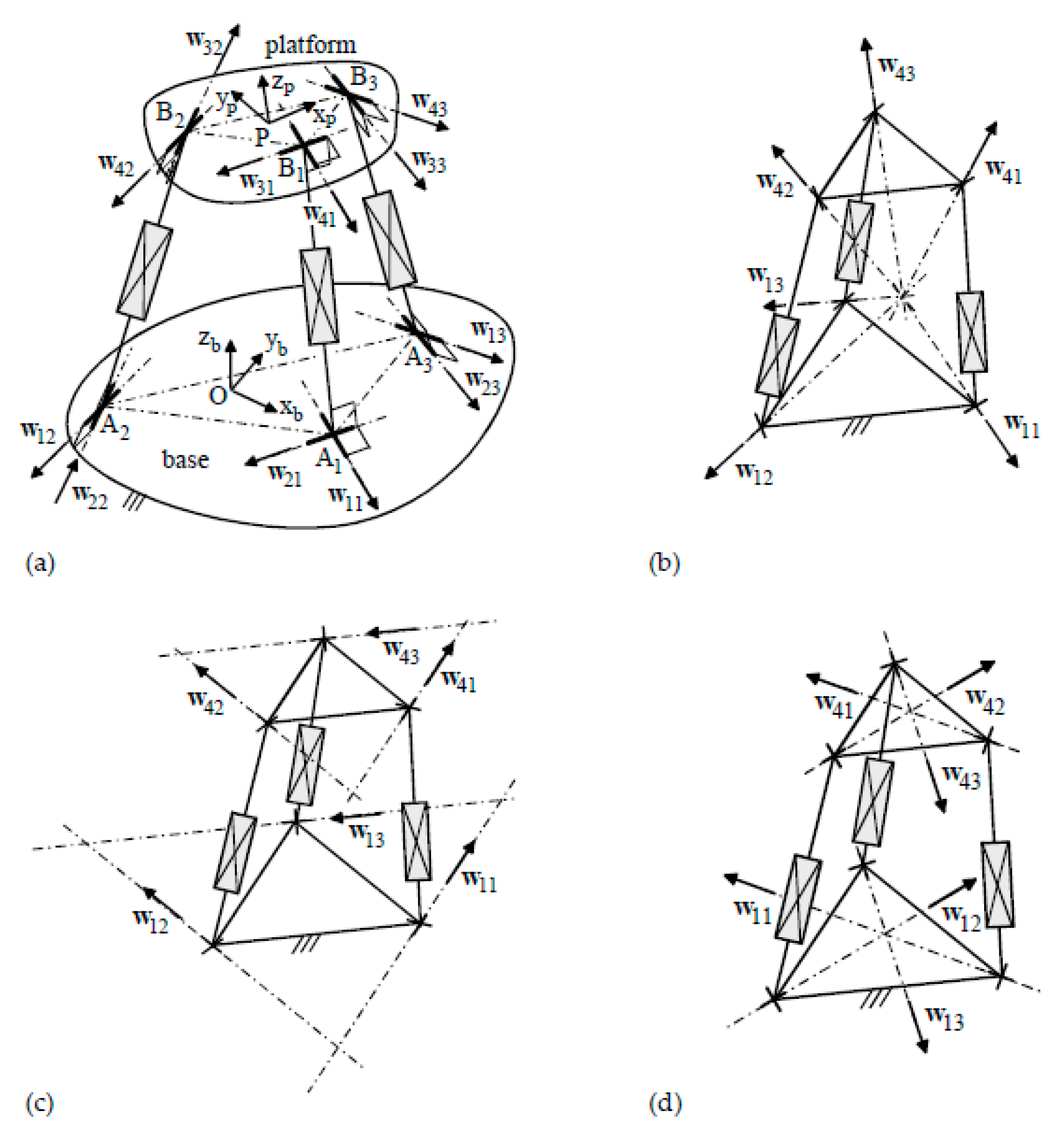
The most common parallel manipulators with three degrees of freedom (DOF) are constituted by two rigid bodies, the end effector (platform) and the frame (base), joined by three kinematic chains (limbs) with the same topology and connectivity1 equal to five. Among these parallel manipulators (PMs), 3-UPU architectures2 (Figure 1) are those with three limbs of UPU type. Such architectures are special cases of the 3-UTU ones, where T denotes a generic single-DOF kinematic pair that makes the axes of the two intermediate R-pairs of the limb translate with respect to one another. A T pair, over a P pair, could be, for instance, an R-pair with axis parallel to the two that have to translate with respect to one another (see Figure 2). Even though most of the literature refers to 3-UPU, the presented results hold for any 3-UTU.
In 1996, Tsai [2] proposed a translational 3-UPU. The Tsai 3-UPU (Figure 1c) had the three R-pair axes fixed in the base (in the platform) in a coplanar arrangement. In [2], Tsai solved, in explicit form, the direct (DPA) and inverse (IPA) position analyses of this translational PM (TPM), which gave two DPA solutions and one IPA solution. Such results made him conclude that the translational 3-UPU was simple to manufacture and to control.
Following Tsai’s proposal, Park built a prototype, named SNU 3-UPU [3,4,5] (Figure 1d), which had the three R-pair axes fixed in the base (in the platform) in a coplanar arrangement and with a common intersection point. In 2001 [3], he presented the prototype and highlighted that the SNU 3-UPU exhibited an unforeseen extra mobility at the home position, which made the platform orientation change. Such strange behavior started animated discussions [3,4,5,6,7,8,9] that, in 2002, identified the constraint singularities [3,6] as the main cause of the strange behavior and as a negative feature that occurs in most of the lower-mobility PMs.
In the meantime, Parenti-Castelli et al. [10,11,12,13,14,15,16] studied more general families of TPMs that included both the Tsai 3-UPU and the SNU 3-UPU. In 1998, Di Gregorio and Parenti-Castelli [10] showed that a PM of 3-RRPRR type becomes a TPM if it is manufactured and assembled out of particular singular configurations (later called constraint singularities [6]), so that, in each RRPRR limb,
- (i)
- the axes of the two intermediate R-pairs are parallel to one another, and
- (ii)
- the axes of the two ending R-pairs are parallel to each other.
Then, from 1999 to 2000, together with Bubani, Di Gregorio and Parenti-Castelli studied in depth the whole family of translational 3-UPUs with the three R-pair axes fixed in the base (in the platform) in a coplanar arrangement. In [11], Di Gregorio and Parenti-Castelli presented the general expressions of the singularity loci of any translational 3-UPU and demonstrated that, in the above-mentioned case of coplanar axes, the rotation (constraint) singularity locus is constituted by a right circular cylinder (Figure 3), which could degenerate [11,12] (Figure 4) for particular platform (base) geometries, and a plane. In the SNU 3-UPU (Figure 1d), the cylinder equation, reported in [11], becomes the equation of a line perpendicular to the base plane and passing through the home position, which explains the strange behavior found by Park. These results were exploited by Parenti-Castelli et al. to build a prototype [13,14] of the Tsai 3-UPU that worked correctly. Later, the same results together with an in-depth analysis of the joint-clearance effects allowed for Bhutani and Dwarakanath [17,18] to build a “high-precision” Tsai 3-UPU that could be used as a measuring machine.
In 2000, Karouia and Hervè [19] identified the geometric conditions that make a 3-UPU architecture become a parallel wrist3 (PW). In particular, by using group theory, they demonstrated that, out of singular configurations, a 3-UPU architecture is a PW (Figure 1b), if
- (a)
- the platform and the base are manufactured so that the three R-pair axes embedded in them have a common intersection point;
- (b)
- each UPU limb (Figure 5) is manufactured and assembled so that the axes of the two intermediate R-pairs are parallel to one another; and
- (c)
- the 3-UPU is assembled so that the axes of the six R-pairs adjacent to the base or to the platform share a common intersection point (such point becomes the spherical motion center).
Karouia and Hervè [19] also advised that such conditions do not exclude the existence of singular configurations where the platform locally acquires an additional translational DOF. Later, Di Gregorio [20,21], by analyzing statics and kinematics of 3-UPU wrists, provided both the geometric (Figure 6) and the analytic conditions that identify the translation (constraint) singularities of these wrists. In [22], Ashith-Shyam and Ghosal presented a 3-UPU wrist prototype for sun tracking; and, in [23,24], Huda and Takeda presented the prototype of a 3-URU wrist for a machine tool and the adopted design methodology.
The consideration that translational 3-UPUs have rotation singularities and 3-UPU wrists have translation singularities pushed Zlatanov et al. [6] to introduce the concept of “constraint singularity” and to highlight that these singularities may occur in any lower-mobility PMs. A constraint singularity is a configuration where a lower-mobility PM may change its operating mode. They may occur when the limbs’ connectivity is higher than the DOF number of the PM. Also, Zlatanov et al. [25] illustrated this concept through the DYMO 3-URU prototype (Figure 7), which exploited its constraint singularities to change its operating mode: It was able to become a TPM, a PW, or a 3-DOF planar PM. DYMO showed for the first time that a 3-UTU can be a reconfigurable machine.
In particular, a 3-UTU can switch from TPM to PW and vice versa if it satisfies conditions (a) and (b) from Karouia and Hervè [19] as stated above; whereas, it can switch from TPM or PW to 3-DOF planar PM and vice versa, if in addition to satisfying conditions (a) and (b), the three R-pair axes fixed in the base (in the platform) are coplanar. The central issue for actually getting a reconfigurable 3-UTU is how to manage the passage through a singular configuration? In [26], Carbonari et al. bypassed the problem by proposing a reconfigurable 3-URU (Figure 8) that could switch from TPM to PW and vice versa at a given non-singular configuration through an ad-hoc-conceived device, which modifies the geometry of the U-joints adjacent to the base. In the same line, Sarabandi et al. [27] presented a particular 3-UPU geometry that can switch from TPM to PW and vice versa by simply turning the platform assembly upside down. This 3-UPU could do the same switch by passing through a singular configuration without disassembling the platform, but the authors did not propose any strategy to go through the singularity.
Eventually, structural singularities of 3-UPU architectures were used to ideate a Shoenflies motion generator [28] of 4-UPU type [29,30,31,32], and a rolling mechanism [33].
This review paper aims at summarizing the relevant analytic and geometric aspects of the above-mentioned results in a unique framework that should be useful for designers and researchers. The paper is organized as follows. Section 2 gives some background concepts and presents the adopted notations together with some general comments. Section 3 and Section 4 analyze translational and wrist architectures, respectively. Then, Section 5 analyzes reconfigurable and structurally singular architectures, and Section 6 draws the conclusions.
2. Background, Notations, and General Comments
The instantaneous input–output relationship of a PM is a linear and homogeneous system that relates the platform twist and the actuated-joint rates. In this relationship, the two coefficient matrices (Jacobians) that multiply the platform twist, and the actuated-joint rates depend only on the PM configuration. Singularities are PM configurations that makes either or both these Jacobians rank-deficient. The PM configuration is not controllable at a singularity. In particular, singularities of the Jacobian that multiplies the platform twist (named parallel singularities) occur inside the reachable workspace, and make the platform gain one or more instantaneous DOFs locally (i.e., they are a particular type of uncertainty configurations [1]). From a statics’ point of view [21], at a parallel singularity, the platform is not able to carry external loads, even small ones, without overloading at least one link (i.e., without breaking down at least one link). Consequently, parallel singularities must be identified during design and avoided during operation by locating the useful workspace in free-from-singularity regions of the operational space.
That is why the possibility of building a particular type of 3-UPU is related to the identification of those geometries that provide wide free-from-singularity regions where the platform can perform only one type of motion (spatial translation (TPMs) or spherical motion (PWs) or planar motion). The following part of this paper illustrates the main results reported in the literature by analyzing the input–output instantaneous relationships of these architectures.
Figure 1a shows a general 3-UPU architecture together with the adopted notations. With reference to Figure 1a,
- -
- Oxbybzb and Pxpypzp are two Cartesian references fixed to the base and the platform, respectively;
- -
- Ai (Bi) for i = 1, 2, 3 are the centers of the U joints adjacent to the base (platform);
- -
- in each UPU limb, the four R-pairs are numbered with an index, j, that increases by moving from the base toward the platform;
- -
- wji, for j = 1, …, 4, is the j-th R-pair axis’ unit vector of the i-th UPU limb, i = 1, 2, 3;
- -
- w2i and w3i are perpendicular to the axis of the i-th limb (i.e., the line through Ai and Bi), for i = 1, 2, 3.
Moreover, the following parameters/vectors are defined:
- -
- θji, for j = 1, …,4, is the angular joint variable, counterclockwise with respect to wji, of the j-th R-pair of the i-th UPU limb, i = 1, 2, 3;
- -
- di = |Bi − Ai| is the linear joint variable of the P-pair (hereafter named “limb length”) of the i-th UPU limb, i = 1, 2, 3;
- -
- p = (P − O); bi = (Bi − O) = p + b0i with b0i = (Bi − P), for i = 1, 2, 3;
- -
- ai = (Ai − O), for i = 1, 2, 3; ci = (b0i − ai) for i = 1, 2, 3; gi = (bi − ai)/di for i = 1, 2, 3;
- -
- ri = w1i × w2i for i = 1, 2, 3; hi = w3i × w4i for i = 1, 2, 3; ni = [(bi − ai)⋅ri] hi for i = 1, 2, 3.
With these notations, the following instantaneous relationships can be written:
where ω is the angular velocity of the platform, and denotes the time derivative of x. Equations (1a), (1b), and (1c) are formally the same that appeared in [34] for the 3-nSPU manipulator and, with the same algebraic manipulations reported in [34], they yield the following instantaneous input–output relationship:
where 1 and 0 are the 3 × 3 identity and null matrices, respectively; is the vector collecting the P-pairs’ joint rates, which are the instantaneous inputs, and
with
GT = (g1, g2, g3), KT = (k1, k2, k3), ST = (s1, s2, s3), JT = (j1, j2, j3)
ki = (bi − p) × gi, si = hi × ri − [gi⋅(hi × ri)] gi, ji = (bi − p) × si − [(bi − ai)⋅ri] hi, i = 1, 2, 3.
System (2) holds for any 3-UPU no matter if it is a TPM or a PW. It becomes specific when the above-mentioned geometric conditions that make the 3-UPU a TPM or a PW are inserted into it. The last three equations of system (2) do not involve the input-joint rates and are general no matter which input variables (i.e., the chosen actuated joints) are used; when their coefficient matrix (i.e., the 3 × 6 matrix [S J]) is rank-deficient, a constraint singularity occurs.
The first three equations of system (2) relate the input-joint rates to the platform twist; in these equations, when the coefficient matrix that multiplies the platform twist (i.e., the 3 × 6 matrix [G K]) is rank deficient, the platform can perform elementary motions without changing its operating mode, even though the actuated joints are locked. These three equations vary together with the associated singularity conditions if the input variables are changed. Nevertheless, if the actuated joints just control the limb lengths, the changes involve only the left-hand sides of these equations, leaving the 3 × 6 matrix [G K] unchanged together with the associated singularities. For instance, with reference to Figure 2, if the actuated P-pair of the i-th limb is replaced by an actuated R-pair with an axis parallel to w2i and w3i, the following relationships hold
whose 1st time derivatives are
Thus, the simple substitution of the right-hand side of Equation (6) for , i = 1, 2, 3 into the left-hand side of system (2) transforms the instantaneous input–output relationship of a 3-UPU into the one of a 3-URU.
3. Translational 3-UTU
The geometric conditions, (i) and (ii), for getting a TPM, with the adopted notations, become (i) w2i = ±w3i and (ii) w1i = ±w4i for i = 1, 2, 3, which yield hi = ±ri, si = 0 and ji = ±[(bi − ai)⋅hi] hi. Consequently, the instantaneous input–output relationship (2) becomes
3.1. Rotation (Constraint) Singularities
By canceling the coefficients ±[(bi − ai)⋅hi]4 the last three equations of system (7) become [12]
hi⋅ω = 0 i = 1, 2, 3.
Equation (8) admits a non-null solution for ω (i.e., a rotation (constraint) singularity occurs) if and only if
h1⋅(h2 × h3) = 0.
From a geometric point of view, Equation (9) is satisfied when the three vectors hi, for i = 1, 2, 3, are coplanar (i.e., when all the intersections among the planes parallel to the U-joints’ cross links are parallel lines). Consequently, if the unit vectors w1i (w4i), for i = 1, 2, 3, are all parallel, this geometric condition is always satisfied5 and a structural rotation (constraint) singularity occurs [29,30,31].
From an analytic point of view [11], Equation (9) is an algebraic equation, whose unknowns are the coordinates of a platform point6 measured in Oxbybzb, which represents a surface (rotation (constraint) singularity locus) in Oxbybzb (the operational space) whose points locate the singular configurations where the platform can rotate. The deduction of this algebraic equation is as follows7:
which yields
and
Since the denominator of expression (12) is constituted by the product of vector magnitudes, it does not provide zeros of Equation (9); hence, in Equation (9), it can be eliminated to give the following algebraic equation of the singularity locus:
whose expansion yields
(w12 ⋅ p) (w13 ⋅ p) [(w12 × w13) ⋅ p] − (w12 ⋅ p){[w12 × (c3 × w13)] ⋅ p} − (w13 ⋅ p) {[(c2 × w12) × w13] ⋅ p} +
+ {[(c2 × w12) × (c3 × w13)] ⋅ p} + (w11 ⋅ p) {[(w13 ⋅ p)w13 − (w12 ⋅ p)w12 − (c3 × w13) + c2 × w12] × w11} ⋅ p +
− (w11 ⋅ p) (w12 ⋅ p) (w13 ⋅ p) [(w12 × w13) ⋅ w11] + (w11 ⋅ p) (w12 ⋅ p) [w12 × (c3 × w13)] ⋅ w11 +
+ (w11 ⋅ p) (w13 ⋅ p) [(c2 × w12) × w13] ⋅ w11 – (w11 ⋅ p) [(c2 × w12) × (c3 × w13)] ⋅ w11 − {[(w13 ⋅ p)w13 +
− (w12 ⋅ p)w12 − (c3 × w13) + c2 × w12] × (c1 × w11)} ⋅ p + (w12 ⋅ p) (w13 ⋅ p) [(w12 × w13) ⋅ (c1 × w11)] +
− (w12 ⋅ p) {[w12 × (c3 × w13)] ⋅ (c1 × w11)} − (w13 ⋅ p) {[(c2 × w12) × w13] ⋅ (c1 × w11)} +
+ [(c2 × w12) × (c3 × w13)] ⋅ (c1 × w11) = 0.
Equation (13) is cubic in the coordinates of point P (see Figure 1a). Since the coefficients that appear in Equation (13) depend on the shape of the platform and base, the rotation (constraint) singularity locus depends only on the platform and base geometries.
In the SNU 3-UPU (Figure 1d), the base (platform) triangle A1A2A3 (B1B2B3) is an equilateral triangle, and the unit vectors w1i (w4i), i = 1, 2, 3, lie on three R-pair axes that have the center of this triangle as a common intersection. By choosing this center as origin O (P), and the triangle plane as the xbyb (xpyp) coordinate plane for Oxbybzb (Pxpypzp), it is easy to realize that, in Equation (13a), the vectors ci × w1i, for i = 1, 2, 3, are all null vectors since ci is parallel to w1i. Consequently, when P lies on the line through O perpendicular to the base triangle A1A2A3 (i.e., the SNU 3-UPU is at its home position), the dot products (w1i ⋅ p), for i = 1, 2, 3, are equal to zero and the left-hand side of Equation (13a), which becomes p ⋅(p × p), is identically equal to zero, that is, the platform can rotate.
In the Tsai 3-UPU (Figure 1c), the base (platform) triangle A1A2A3 (B1B2B3) is an equilateral triangle, but the i-th unit vector w1i (w4i), i = 1, 2, 3, is parallel to the base-triangle (platform-triangle) side opposite to the vertex Ai (Bi), which the corresponding R-pair axis passes through. For this geometry, Equation (13) yields, as a singularity locus, a cubic surface (see [14]), that is the product of the base-triangle plane by a right circular cylinder whose generatrix is a line perpendicular to the base-triangle plane. The analytic expression of this cylinder is reported in [14].
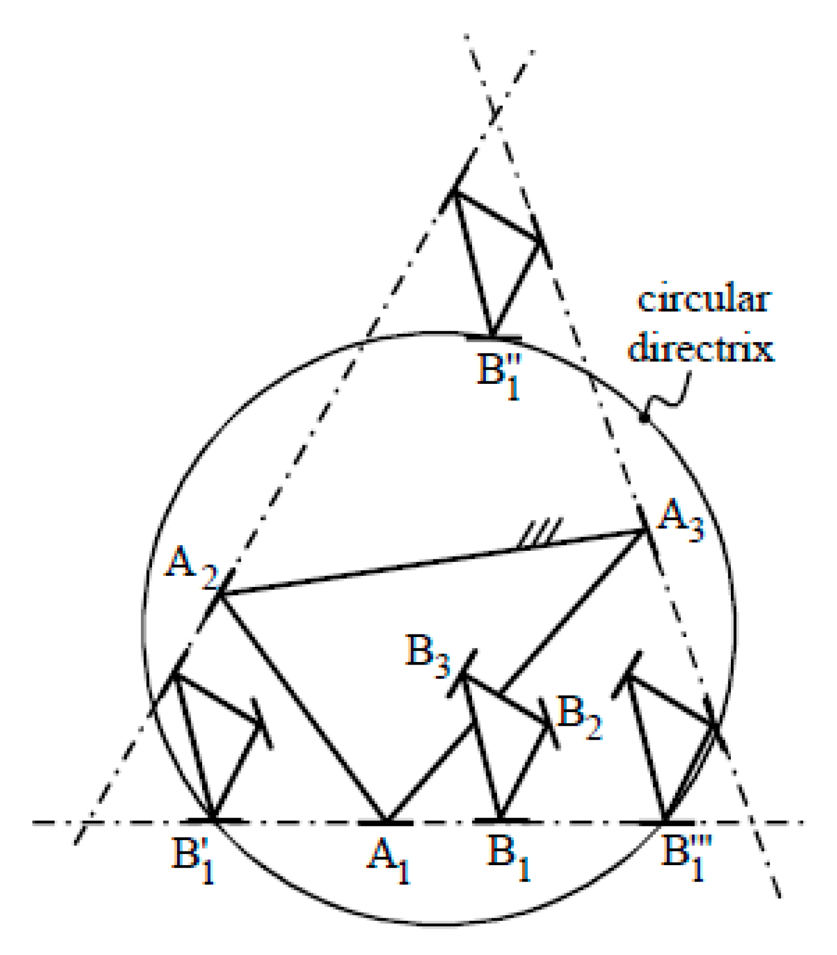
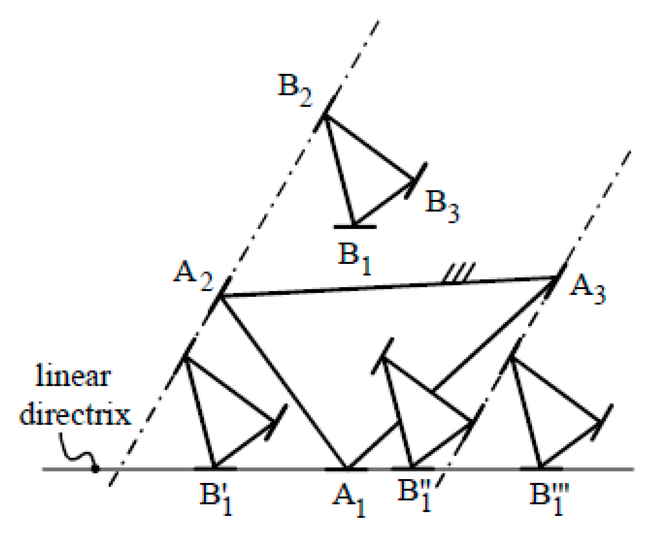
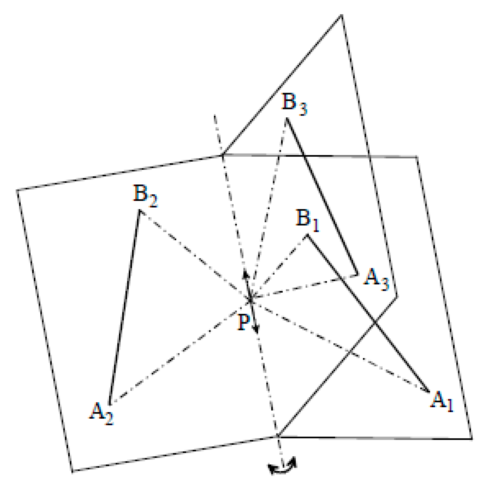
The set of all the 3-UPUs with the axes of the three R-pairs, adjacent to the base (platform), that lie on the plane of the base (platform) triangle contains both SNU and Tsai 3-UPUs. This set was studied in [12]. The introduction of the geometric conditions that identify this set into Equation (13) shows that [12] the rotation (constraint) singularity locus of all these 3-UPUs is always the product of the base-triangle plane by a right circular cylinder whose generatrix is a line perpendicular to the base-triangle plane. By choosing A1 (B1) as origin O (P), and the base-triangle (platform-triangle) plane as xbyb (xpyp) coordinate plane for Oxbybzb (Pxpypzp), the analytic expression of this cylinder is reported in [12] together with the simple geometric construction shown in Figure 3, which allows to draw immediately the singularity cylinder. The construction of Figure 3 relies on the fact that three points are sufficient to identify a circle, and that three singularities, B1’, B1’’ and B1’’’ in Figure 3, are easy to find. The same construction highlights (Figure 4) that, when any two R-pair axes (together with the corresponding unit vectors w1i) are parallel, the singularity cylinder degenerates into a singularity plane (see [12] for details).
3.2. Translation Singularities
Out of rotation singularities, the platform angular velocity, ω, is a null vector. Thus, the first three equations of system (7) become [12]:
When the actuators are locked, Equations (14) admit a non-null solution for (i.e., a translation singularity occurs) if and only if
g1⋅(g2 × g3) = 0.
From a geometric point of view, Equation (15) is satisfied when the three unit vectors gi, for i = 1, 2, 3, are parallel to a plane (i.e., when all the limb axes are parallel to a unique plane). If the base and platform triangles are equal, this condition is always satisfied and a structural translation singularity occurs [2,12].
From an analytic point of view [11], Equation (15) is an algebraic equation, whose unknowns are the coordinates of a platform point measured in Oxbybzb, which represents a surface (translation singularity locus) in Oxbybzb whose points locate the singular configurations where the platform translation is not controllable by the actuators. The deduction of this algebraic equation is as follows:
Since the denominator of expression (16) is constituted by the product of the limb lengths, it does not provides zeros of Equation (15); hence, in Equation (15), it can be eliminated to give the following algebraic equation of the singularity locus
whose expansion is
p⋅{[(b03 − a3) × (b01 − a1)] + [(b01 − a1) × (b02 − a2)] + [(b02 − a2) × (b03 − a3)]} + (b01 − a1) ⋅ [(b02 − a2) × (b03 − a3)] = 0.
Equation (17b) is linear in the coordinates of P. Therefore, the translation singularity locus is always a plane [11], which is perpendicular to the vector in curly brackets that dot multiplies p in Equation (17b). By choosing A1 (B1) as origin O (P), and the base-triangle (platform-triangle) plane as the xbyb (xpyp) coordinate plane for Oxbybzb (Pxpypzp), it is easy to realize that, if the base and platform triangles are equal, the vectors (b0i − ai), for i = 1, 2, 3, are all null vectors. Consequently, the left-hand side of Equation (17b) is identically null (i.e., a structural singularity occurs). Also, in the case of the 3-UPUs with the axes of the three R-pairs, adjacent to the base (platform), that lie on the plane of the base (platform) triangle, it is easy to realize that the singularity plane is the base-triangle plane [12]. Indeed, in this case, the vectors (b0i − ai), for i = 1, 2, 3, are all parallel to the base plane, which implies that, in Equation (17b), the mixed product (b01 − a1) ⋅ [(b02 − a2) × (b03 − a3)] is equal to zero and the vector in curly brackets is perpendicular to the base-triangle plane.
4. 3-UTU Wrist
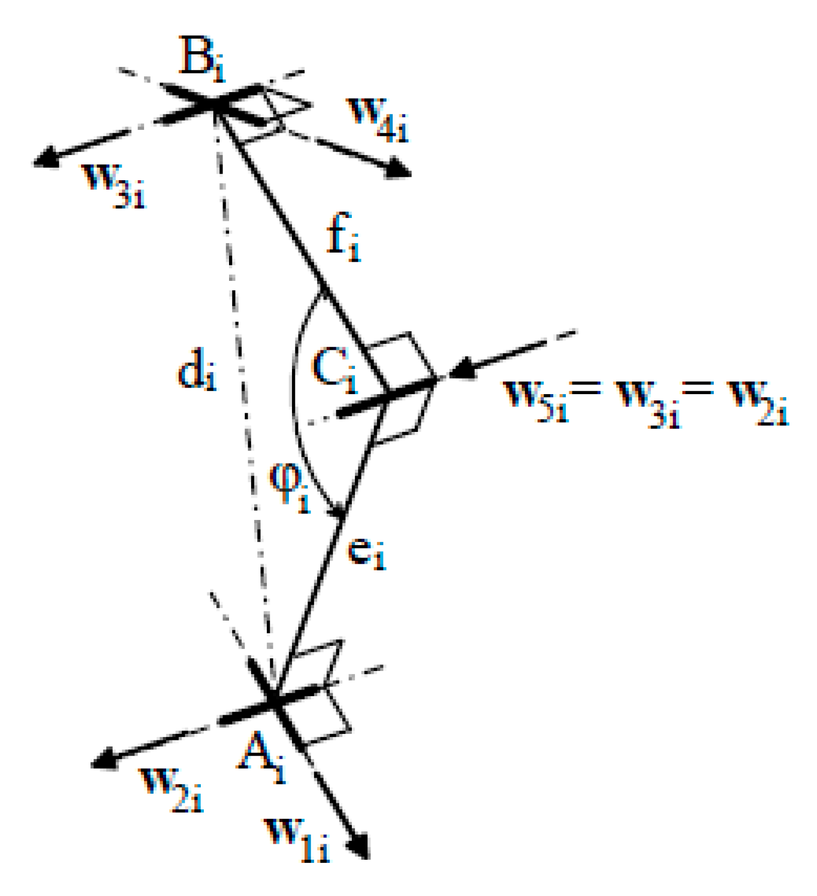
The geometric condition (a) for getting a PW, allows for the choice of the point O (P), see Figure 1a,b, coincident with the common intersection point of the three axes of the R-pairs adjacent to the base (platform). Such a choice makes ai (bi) parallel to w1i (w4i), for i = 1, 2, 3. In addition, condition (b) yields w2i = ±w3i; whereas, condition (c) implies that O coincides with P (i.e., p = 0). Consequently, ki = bi × gi, si = hi × ri since gi is perpendicular to hi × ri, and ji = 0, for i = 1, 2, 3 (see Equation (4)). These formulas allow for the conclusion that ki and si are both parallel to w2i and w3i (see Figure 5), which are unit vectors perpendicular to the plane of the triangle AiBiP.
Therefore, the instantaneous input–output relationship (2) for the 3-UPU wrist becomes
4.1. Translation (Constraint) Singularities
The last three equations of system (18) become
Equations (19) admit a non-null solution for (i.e., a translation (constraint) singularity occurs) if and only if
which, since si is parallel to w2i for i = 1, 2, 3, can be simplified as follows [20,21]:
s1 ⋅ (s2 × s3) = 0,
w21 ⋅ (w22 × w23) = 0.
Equation (20b) is satisfied when the three vectors w2i, for i = 1, 2, 3, are all parallel to a unique plane, that is, when the planes of the three triangles AiBiP, for i = 1, 2, 3, have a line as a common intersection (Figure 6) [20]. Also, it is worth noting that each unit vector w2i is indeterminate when the triangle AiBiP is flattened (i.e., the points Ai, Bi, and P are aligned); in this case (see Figure 5), a simple inspection of the flattened limb reveals that the i-th limb can freely rotate around its axis.
4.2. Rotation Singularities
Out of the translation singularities, is a null vector. Thus, the first three equations of system (18) become [20]:
When the actuators are locked, Equation (21) admit a non-null solution for ω (i.e., a rotation singularity occurs) if and only if
which, since ki is parallel to w2i for i = 1, 2, 3, can be simplified as follows [20,21]:
k1⋅(k2 × k3) = 0,
w21 ⋅ (w22 × w23) = 0.
Equation (22b) coincides with Equation (20b). Thus, the locus of the rotation singularities coincides with that of the translation (constraint) singularities in a 3-UPU wrist.
5. Reconfigurable and Structurally Singular 3-6UTUs
The presence of constraint singularities in 3-UTUs allows for the building of reconfigurable PMs, that is, machines that can change their operating mode. In [25], Zlatanov et al. presented DYMO (Figure 7a), a 3-URU that is able to become a TPM (Figure 7b), a PW (Figure 7c), or a 3-DOF planar PM (Figure 7d). DYMO (Figure 7a) satisfies geometric conditions (a) and (b), and has the three R-pair axes fixed in the base (in the platform) in a coplanar arrangement. So, the constraint singularity that occurs when the intersection of the three R-pair axes fixed in the platform coincides with the intersection of the three R-pair axes fixed in the base is present in all the three operating modes and can be exploited to change the operating mode.
Unfortunately, the platform pose is out of control at a constraint singularity, and this simple method for reconfiguring the machine cannot be implemented. Carbonari et al. [26] bypassed the problem by proposing a reconfigurable 3-URU that could switch from TPM to PW and vice versa at a given non-singular configuration. Their 3-URU (Figure 8) satisfies conditions (a) and (b), and adopts an ad-hoc-conceived device, which modifies the geometry of the U-joints adjacent to the base. In the same line, Sarabandi et al. [27] presented a particular 3-UPU geometry that satisfies conditions (a) and (b) and can switch from TPM to PW and vice versa by simply turning the platform assembly upside down.
The rotation (constraint) structural singularity (see Section 3.1) that occurs in translational 3-UPUs when (Figure 1) the unit vectors w1i (w4i), for i = 1, 2, 3, are all parallel makes the platform able to rotate around axes parallel to these unit vectors. Such additional finite DOF allows for the introduction of one more UPU limb to control the platform rotation. The resulting 4-UPU is a Shoenflies motion generator [28]. It was presented in [29] and studied in [30,31,32].
Eventually, in a translational 3-UPU, if, over the above-mentioned structural singularity, the structural translation singularity (see Section 3.2) that occurs when the platform and base triangles are equal is introduced, the resulting 3-UPU acquires two additional finite DOFs: one rotation and one translation. Such a geometry has been used in [33] to conceive a 5-DOF rolling mechanism able to move on the floor.
6. Conclusions
A critical review of the extensive literature on 3-UTU architectures has been presented. The presented review allows for the following conclusions: The study of these architectures contributed to the mechanism theory by revealing the presence of “constraint singularities” in most of the lower-mobility PMs. All the design tools have been developed for both translational 3-UPUs and 3-UPU wrists. Even though commercial robots with these architectures are not present on the market, prototypes that work correctly have been built, and the structural singularities of these architectures have been exploited. The majority of the published works on the translational 3-UTUs refer to the set of 3-UTUs with coplanar axes of the three R-pairs adjacent to the base (platform).
Possible future research on these architectures should investigate translational 3-UTUs with base and platform geometries in which the R-pair axes are not coplanar and strategies to pass through a constraint singularity.
Funding
This work has been developed at the Laboratory of Mechatronics and Virtual Prototyping (LaMaViP) of Ferrara Technopole, supported by FAR2019 UNIFE funds.
Conflicts of Interest
The author declares no conflict of interest.
References
- Hunt, K.H. Kinematic Geometry of Mechanisms; Clarendon Press: Oxford, UK, 1990. [Google Scholar]
- Tsai, L.W. Kinematics of a Three-dof Platform with Three Extensible Limbs. In Recent Advances in Robot Kinematics; Lenarcic, J., Parenti-Castelli, V., Eds.; Kluwer Academic Publishers: Dordrecht, The Netherlands, 1996; pp. 401–410. ISBN 978-94-010-7269-4. [Google Scholar]
- Bonev, I.; Zlatanov, D. The Mystery of the Singular SNU Translational Parallel Robot. ParalleMIC-The Parallel Mechanisms Information Center, (http://www.parallemic.org) 12 June 2001. Available online: https://www.parallemic.org/Reviews/Review004.html (accessed on 18 October 2019).
- Han, C.; Kim, J.; Kim, J.; Park, F.C. Kinematic sensitivity analysis of the 3-UPU parallel mechanism. Mech. Mach. Theory 2002, 37, 787–798. [Google Scholar] [CrossRef]
- Walter, D.R.; Husty, M.L.; Pfurner, M. A complete kinematic analysis of the SNU 3-UPU parallel robot. In Interactions of Classical and Numerical Algebraic Geometry; Bates, D.J., Besana, G.M., Di Rocco, S., Wampler, C.W., Eds.; Contemporary Mathematics; AMS: Providence, RI, USA, 2009; Volume 496, pp. 331–346. ISBN 978-0-8218-4746-6. [Google Scholar]
- Zlatanov, D.; Bonev, I.A.; Gosselin, C.M. Constraint singularities of parallel mechanisms. In Proceedings of the IEEE International Conference on Robotics and Automation, Washington, DC, USA, 11–15 May 2002; pp. 496–502. [Google Scholar] [CrossRef]
- Joshi, S.A.; Tsai, L.W. Jacobian analysis of limited-DOF parallel manipulators. ASME J. Mech. Des. 2002, 124, 254–258. [Google Scholar] [CrossRef]
- Wolf, A.; Shoham, M.; Park, F.C. Investigation of singularities and self-motions of the 3-UPU robot. In Advances in Robot Kinematics; Lenaric, J., Thomas, F., Eds.; Kluwer: Norwell, MA, USA, 2002; pp. 165–174. ISBN 978-90-481-6054-9. [Google Scholar]
- Liu, G.; Lou, Y.; Li, Z. Singularities of Parallel Manipulators: A Geometric Treatment. IEEE Trans. Rob. Autom. 2003, 19, 579–594. [Google Scholar] [CrossRef]
- Di Gregorio, R.; Parenti-Castelli, V. A Translational 3-DOF Parallel Manipulator. In Advances in Robot Kinematics: Analysis and Control; Lenarcic, J., Husty, M.L., Eds.; Kluwer: Norwell, MA, USA, 1998; pp. 49–58. ISBN 978-90-481-5066-3. [Google Scholar]
- Di Gregorio, R.; Parenti-Castelli, V. Influence of the geometric parameters of the 3–UPU parallel mechanism on the singularity loci. In Proceedings of the International Workshop on Parallel Kinematic Machines (PKM’99), Milan, Italy, 30 November 1999; pp. 79–86, ISBN 88-900426-0-5. [Google Scholar]
- Di Gregorio, R.; Parenti-Castelli, V. Mobility analysis of the 3–UPU parallel mechanism assembled for a pure translational motion. ASME J. Mech. Des. 2002, 124, 259–264. [Google Scholar] [CrossRef]
- Parenti-Castelli, V.; Bubani, F. Singularity loci and dimensional design of a translational 3-dof fully-parallel manipulator. In Advances in Multibody Systems and Mechatronics; Kecskemeéthy, A., Schneider, M., Woernle, C., Eds.; Technische Universität Graz. Institut für Mechanik und Getriebelehre: Duisburg, Germany, 1999; pp. 319–331. ISBN 9783950110807. [Google Scholar]
- Parenti-Castelli, V.; Di Gregorio, R.; Bubani, F. Workspace and Optimal Design of a Pure Translational Parallel Manipulator. Meccanica 2000, 35, 203–214. [Google Scholar] [CrossRef]
- Di Gregorio, R.; Parenti-Castelli, V. Benefits of twisting the legs in the 3-UPU Tsai mechanism. In Proceedings of the Year 2000 Parallel Kinematic Machines International Conference, Ann Arbor, MI, USA, 13–15 September 2000; pp. 201–211. [Google Scholar]
- Di Gregorio, R.; Parenti-Castelli, V. A New Approach for the evaluation of kinematic and static performances of a family of 3-UPU translational manipulators. In Romansy 16: Robot Design, Dynamics, and Control; Zielińska, T., Zieliński, C., Eds.; Springer: Vienna, Austria, 2006; pp. 47–54. ISBN 978-3-211-36064-4. [Google Scholar]
- Bhutani, G.; Dwarakanath, T.A. Practical feasibility of a high-precision 3-UPU parallel mechanism. Robotica 2014, 32, 341–355. [Google Scholar] [CrossRef]
- Bhutani, G.; Dwarakanath, T.A. Novel design solution to high precision 3 axes translational parallel mechanism. Mech. Mach. Theory 2014, 75, 118–130. [Google Scholar] [CrossRef]
- Karouia, M.; Hervé, J.M. A three-dof tripod for generating spherical rotation. In Advances in Robot Kinematics; Lenarcic, J., Stanisic, M.M., Eds.; Springer: Dordrecht, The Netherlands, 2000; pp. 396–402. ISBN 978-94-010-5803-2. [Google Scholar]
- Di Gregorio, R. Kinematics of the 3-UPU wrist. Mech. Mach. Theory 2003, 38, 253–263. [Google Scholar] [CrossRef]
- Di Gregorio, R. Statics and singularity loci of the 3-UPU wrist. IEEE Trans. Robot. 2004, 20, 630–635. [Google Scholar] [CrossRef]
- Ashith Shyam, R.B.; Ghosal, A. Path planning of a 3-UPU wrist manipulator for sun tracking in central receiver tower systems. Mech. Mach. Theory 2018, 119, 130–141. [Google Scholar] [CrossRef]
- Huda, S.; Takeda, Y. Kinematic analysis and synthesis of a 3-URU pure rotational parallel mechanism with respect to singularity and workspace. J. Adv. Mech. Des. Syst. Manuf. 2007, 1, 81–92. [Google Scholar] [CrossRef] [Green Version]
- Huda, S.; Takeda, Y. Kinematic Design of 3-URU Pure Rotational Parallel Mechanism with Consideration of Uncompensatable Error. J. Adv. Mech. Des. Syst. Manuf. 2008, 2, 874–886. [Google Scholar] [CrossRef] [Green Version]
- Zlatanov, D.; Bonev, I.A.; Gosselin, C.M. Constraint Singularities as C-Space Singularities. In Advances in Robot Kinematics: Theory and Applications; Lenarčič, J., Thomas, F., Eds.; Springer: Dordrecht, The Netherlands, 2002; pp. 183–192. ISBN 978-90-481-6054-9. [Google Scholar]
- Carbonari, L.; Corinaldi, D.; Palpacelli, M.; Palmieri, G.; Callegari, M. A Novel Reconfigurable 3-URU Parallel Platform. In Advances in Service and Industrial Robotics; Ferraresi, C., Quaglia, G., Eds.; Springer: Dordrecht, The Netherlands, 2018; pp. 63–73. ISBN 978-3-319-61275-1. [Google Scholar]
- Sarabandi, S.; Grosch, P.; Porta, J.M.; Thomas, F. A Reconfigurable Asymmetric 3-UPU Parallel Robot. In Proceedings of the 2018 International Conference on Reconfigurable Mechanisms and Robots (ReMAR2018), Deft, The Netherlands, 20–22 June 2018; pp. 2–9. [Google Scholar]
- Hervé, J.M. The lie group of rigid body displacements, a fundamental tool for mechanism design. Mech. Mach. Theory 1999, 34, 719–730. [Google Scholar] [CrossRef]
- Zhao, T.S.; Dai, J.S.; Huang, Z. Geometric Analysis of Overconstrained Parallel Manipulators with Three and Four Degrees of Freedom. JSME Int. J. Ser. C 2002, 45, 730–740. [Google Scholar] [CrossRef] [Green Version]
- Zhao, T.S.; Li, Y.W.; Chen, J.; Wang, J.C. Novel Four-DOF Parallel Manipulator Mechanism and Its Kinematics. In Proceedings of the 2006 IEEE Conference on Robotics, Automation and Mechatronics (RAM 2006), Bangkok, Thailand, 1–3 June 2006. [Google Scholar] [CrossRef]
- Solazzi, M.; Gabardi, M.; Frisoli, A.; Bergamasco, M. Kinematics Analysis and Singularity Loci of a 4-UPU Parallel Manipulator. In Advances in Robot Kinematics; Lenarcic, J., Khatib, O., Eds.; Springer: Cham, Switzerland, 2014; pp. 467–474. ISBN 978-3-319-06698-1. [Google Scholar]
- Coste, M.; Demdah, K.M. Extra Modes of Operation and Self-Motions in Manipulators Designed for Schoenflies Motion. ASME J. Mech. Rob. 2015, 7, 041020. [Google Scholar] [CrossRef]
- Miao, Z.; Yao, Y.; Kong, X. A rolling 3-UPU parallel mechanism. Front. Mech. Eng. 2013, 8, 340–349. [Google Scholar] [CrossRef]
- Grosch, P.; Di Gregorio, R.; Thomas, F. Generation of under-actuated manipulators with non-holonomic joints from ordinary manipulators. ASME J. Mech. Rob. 2010, 2, 011005. [Google Scholar] [CrossRef] [Green Version]
- Roberson, R.E.; Schwertassek, R. Dynamics of Multibody Systems; Springer: New York, NY, USA, 1988; p. 77. ISBN 978-3-642-86466-7. [Google Scholar]
- Palpacelli, M.; Carbonari, L.; Palmieri, G.; Callegari, M. Design of a Lockable Spherical Joint for a Reconfigurable 3-URU Parallel Platform. Robotics 2018, 7, 42. [Google Scholar] [CrossRef] [Green Version]
| 1 | According to [1], here, we use the term “limb connectivity” to denote the DOF number the platform would have if it were connected to the base only through that limb. |
| 2 | Hereafter, U, S, R, and P stand for universal joint, spherical pair, revolute pair, and prismatic pair, respectively. Also, the underscore denotes an actuated kinematic pair. |
| 3 | Parallel wrists (PWs) are PMs in which the relative motion between platform and base can only be a spherical motion with a fixed center. |
| 4 | Since this coefficient has no effect on the value of ω when it is different from zero, the value of ω as this coefficient goes to zero is unchanged. Therefore, the zeroing of this coefficient does not affect the angular velocity of the platform and does not identify a rotation (constraint) singularity. |
| 5 | Indeed, in this case, all the intersections among the cross-links’ planes are lines parallel to the unit vectors w1i (w4i). |
| 6 | In TPMs, the coordinates of a platform point are sufficient to identify the platform pose in the operational space since the platform translates with respect to the base. |
| 7 | Note that, in a TPM, the above-defined vectors ci (= b0i − ai), i = 1, 2, 3, are constant vectors since the platform translates. |
Figure 1.
3-UPU architectures: (a) general geometry and notations, (b) 3-UPU wrist, (c) Tsai 3-UPU, (d) SNU 3-UPU.
Figure 1.
3-UPU architectures: (a) general geometry and notations, (b) 3-UPU wrist, (c) Tsai 3-UPU, (d) SNU 3-UPU.

Figure 2.
The i-th limb of a 3-URU.

Figure 3.
Singularity cylinder: graphic determination of the circular directrix.

Figure 4.
Case with two parallel R-pair axes: The circular directrix of the singularity cylinder degenerates into a linear directrix (i.e., the cylinder degenerates into a plane).
Figure 4.
Case with two parallel R-pair axes: The circular directrix of the singularity cylinder degenerates into a linear directrix (i.e., the cylinder degenerates into a plane).

Figure 5.
The i-th limb of a 3-UPU wrist.

Figure 6.
Singular configuration of a 3-UPU wrist.

Figure 7.
DYMO 3-URU: (a) 3D model, (b) translational parallel manipulator (TPM) operating mode, (c) parallel wrist (PW) operating mode, (d) 3-DOF planar PM operating mode. Figures downloaded from http://www.parallemic.org/Reviews/Review008.html and reproduced with the permission of the authors.
Figure 7.
DYMO 3-URU: (a) 3D model, (b) translational parallel manipulator (TPM) operating mode, (c) parallel wrist (PW) operating mode, (d) 3-DOF planar PM operating mode. Figures downloaded from http://www.parallemic.org/Reviews/Review008.html and reproduced with the permission of the authors.

Figure 8.
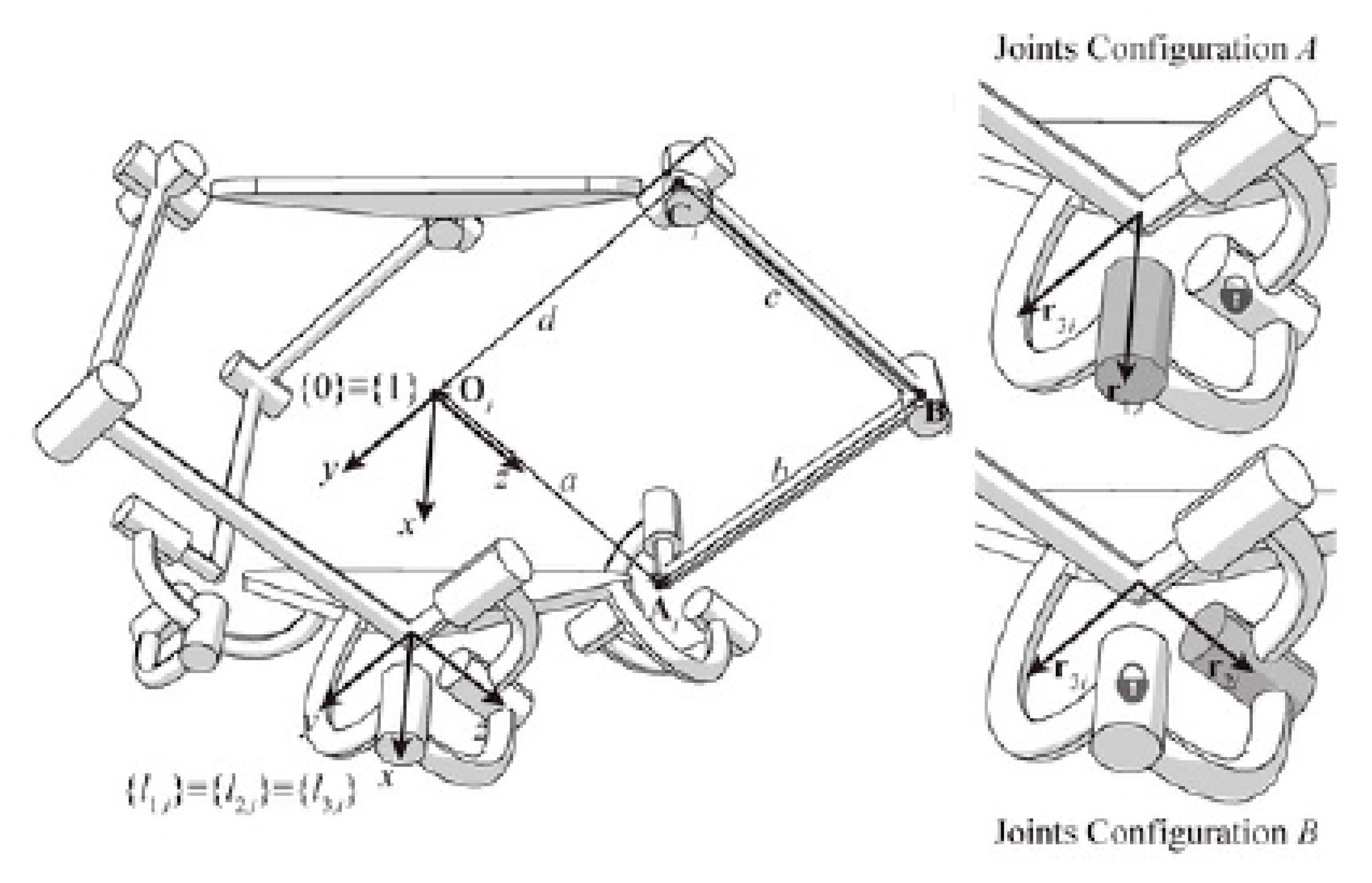
Carbonari et al. reconfigurable 3-URU [26]: Joint configurations A and B refer to the TPM and PW modes, respectively, the padlock denotes the locked R-pair, the darker R-pair is the actuated pair. Figure downloaded from [36] https://www.mdpi.com/2218-6581/7/3/42 and reproduced with the permission of the authors.
Figure 8.
Carbonari et al. reconfigurable 3-URU [26]: Joint configurations A and B refer to the TPM and PW modes, respectively, the padlock denotes the locked R-pair, the darker R-pair is the actuated pair. Figure downloaded from [36] https://www.mdpi.com/2218-6581/7/3/42 and reproduced with the permission of the authors.

© 2020 by the author. Licensee MDPI, Basel, Switzerland. This article is an open access article distributed under the terms and conditions of the Creative Commons Attribution (CC BY) license (http://creativecommons.org/licenses/by/4.0/).
Share and Cite
MDPI and ACS Style
Di Gregorio, R. A Review of the Literature on the Lower-Mobility Parallel Manipulators of 3-UPU or 3-URU Type. Robotics 2020, 9, 5. https://doi.org/10.3390/robotics9010005
AMA Style
Di Gregorio R. A Review of the Literature on the Lower-Mobility Parallel Manipulators of 3-UPU or 3-URU Type. Robotics. 2020; 9(1):5. https://doi.org/10.3390/robotics9010005
Chicago/Turabian StyleDi Gregorio, Raffaele. 2020. "A Review of the Literature on the Lower-Mobility Parallel Manipulators of 3-UPU or 3-URU Type" Robotics 9, no. 1: 5. https://doi.org/10.3390/robotics9010005
Note that from the first issue of 2016, this journal uses article numbers instead of page numbers. See further details here.