1. Introduction
WHO (World Health Organization), or rather the WHOQOL (World Health Organization Quality of Life) group, has developed a test instrument to evaluate the quality of life, as a complement to a standard health assessment. The instrument had questions within the following domains: physical, psychological, level of independence, social relationships, environment, and spirituality/religion/personal beliefs. Within the domain “level of independence” WHO has the following facets: mobility, activities of daily living, dependence on medicinal substances and medical aids, dependence on non-medical substances (alcohol, tobacco, drugs), communication capacity, and work capability [
1]. The independency and possibility to manage activities of daily living are taken into account as one of the important abilities.
Undernutrition is a serious problem amongst the elderly. For example, elderly people in Scandinavia have a high risk of malnutrition and eating difficulty is a risk factor for it according to Nyberg et al. [
2]. Japan and Sweden share the same problem with the demographical development, and both countries are robot and technical-friendly. This gives a common goal to manage to take care of the elderly.
Up to now, several robotic systems for eating have been introduced. Handy 1 is an assisting robotic system, which is composed of a robotic arm that works with different trays, depending on the task. For eating, it has a tray with different compartments, where different kinds of food can be placed and the user chooses what compartment to take from. It was also designed to assist other activities than eating, such as drinking, and make-up application, which requires different kinds of detachable slide-on tray sections and end effectors [
3]. Developments of robotic assistive eating devices with chopstick-type gripper have been done in Japan [
4]. The mechanism in [
4] is based on an industrial robot-like arm. The meal assistance robot “My Spoon” is composed of a manipulator arm with 5-DOFs and an end-effector that is controlled by a joystick. As the end effector has a spoon and a fork that together work as a pincer, it picks up food between the spoon and fork and lifts it up to the mouth and, when the user touches the spoon, the fork folds back to release the bite. The food is put into a box with four compartments [
5,
6]. The “Neater Eater” started as a 2-DOF arm robot with a spoon as the end-effector, which is moved by the user with a damping mechanism that absorbs tremor [
7]. Now that the Neater Eater robotic V6 has been developed [
8]. It takes the food by turning the plate and scrape towards the brim and can be controlled by a touch screen. The “Meal Buddy” has a 3-DOF robotic arm and a spoon as the end-effector, and it has three bowls for the food that are mounted on a board using magnets. It is possible to choose different ways of control devices [
9]. “Obi” is one of the newest eating devices on the market. Obi’s base shape has similarities to a drop and the arm is situated on the right side of the plate that has four compartments/bowls to put the food in. It is white and has 6-DOF. It is controlled by the user with two buttons, one for choosing which one of the four compartments with food to take from, and the other button for starting the grasping of food and lifting to the mouth. The LARM [
10] clutched arm is driven by a single actuator from which the motion is transmitted to its joints with the help of gears and electromagnetic clutches. The arm has a parallelogram-based mechanism for the limb part, which drives the upper arm and forearm from the shoulder. Even though the kinematic design has been considerably simplified, the system can be only used for eating and the end-effector cannot adapt to the stiffness of the grasped food. An assistive robot for self-feeding that is capable of handling Korean food, including sticky rice, has been introduced in [
11]. It is composed of a dual-arm manipulator with a total of 6-DOF (without the gripper). The first robotic arm (spoon-arm) uses a spoon to transfer the food from a container on a table to the user’s mouth. The second robotic arm picks food up from a container and then puts it on the spoon of a spoon-arm. The level of cognitive load to the user increases and two different tools are required while eating due to the use of the dual-arm manipulation.
In most cases mentioned above, meal assistant robots/systems are basically composed of a robot arm to move the gripping tool of foods, such as spoon and chopsticks. From the point of view of real use of meal assistant robot for the promotion of independent life of elderly, it is very important to consider safety, how it looks, sounds, and so on, as well as the complexity of the mechanical design, the total cost of the system and power consumption.
Based on the background and discussions mentioned above, we have undertaken development/research in order to promote an independent life of elderly people by a multi grip tool to facilitate eating. To raise the standard of living of the elderly from the viewpoint of eating habits, Japan–Swedish industry-academia collaboration program began in 2017 [
12]. In this project, we used the eating aid Bestic. The initiative to Bestic came from Sten Hemmingsson, who had the need for the product himself and who wanted to be able to continue eating independently. The product development is described in the report “Bestic An eating-aid for persons with little or no ability to move their arms” [
13]. The product has continued developing with the influence of users [
14]. Our research team aimed to expand its function by attaching a gripper instead of a spoon to Bestic developed at Camanio Care AB in Sweden.
We aimed to enhance the functionalities of Bestic in order to enable frail elderly to have an independent meal experience and reduce caregiver’s burden. For this purpose, in this research, we aimed to further develop the current commercial version of Bestic for targeting current Bestics’ users as well as frail and dependent elderly. Therefore, we focused on developing different kinds de-attachable multigrip tools that can passively adapt to the stiffness of the grasped object as well as integrating the vision system for enhancing the usability of the proposed system (e.g., vision-based control). In particular, in this research, we aimed to adapt the eating device Bestic to Japanese eating customs, and we developed a chopstick-type gripper that allows users to properly eat Japanese food as well as to perform other daily life activities.
Regarding multigrip tools, chopsticks are widely used because of its usefulness in picking up many kinds of foods and its very simple composition. Although using chopsticks looks like needing dexterous operation by human’s fingers, since it can be used to do various manipulation of foods, such as picking up, cutting, sticking, and so on; it can actually be used easily once the purpose of use has been adequately narrowed. In this paper, we rather focus on the picking up operation of chopsticks and propose a reasonable design of a gripper mechanism that employs an under actuation principle to make the gripper adaptable against various size and stiffness of foods by solely using position control and without introducing force sensors. “Solely use” means that the gripper only has “open” or “close” states, and a control system only gives maximum or minimum positions to the actuator corresponding to each state. In order to calculate the configuration of the mechanism against the given property of the target food and the actuator input, and to figure out a suitable design of the gripper and grasp planning which derives the motor input angle and the contact position with the target object, in order to realize a simple control system, Kineto-elasto-static analysis was performed in this paper. Also, an effect of the stiffness error on the gripping force is investigated. An experiment using the prototype to measure the contact force was conducted to validate the modeling of the mechanism and the feature of the mechanism obtained by the kineto-elasto-static analysis. Finally, the gripper prototype was implemented in a 6-DOF robotic arm and the grasp planning experiment was carried out to demonstrate the feasibility of the proposed grasp planning.
3. Chopstick-Type Gripper Mechanism
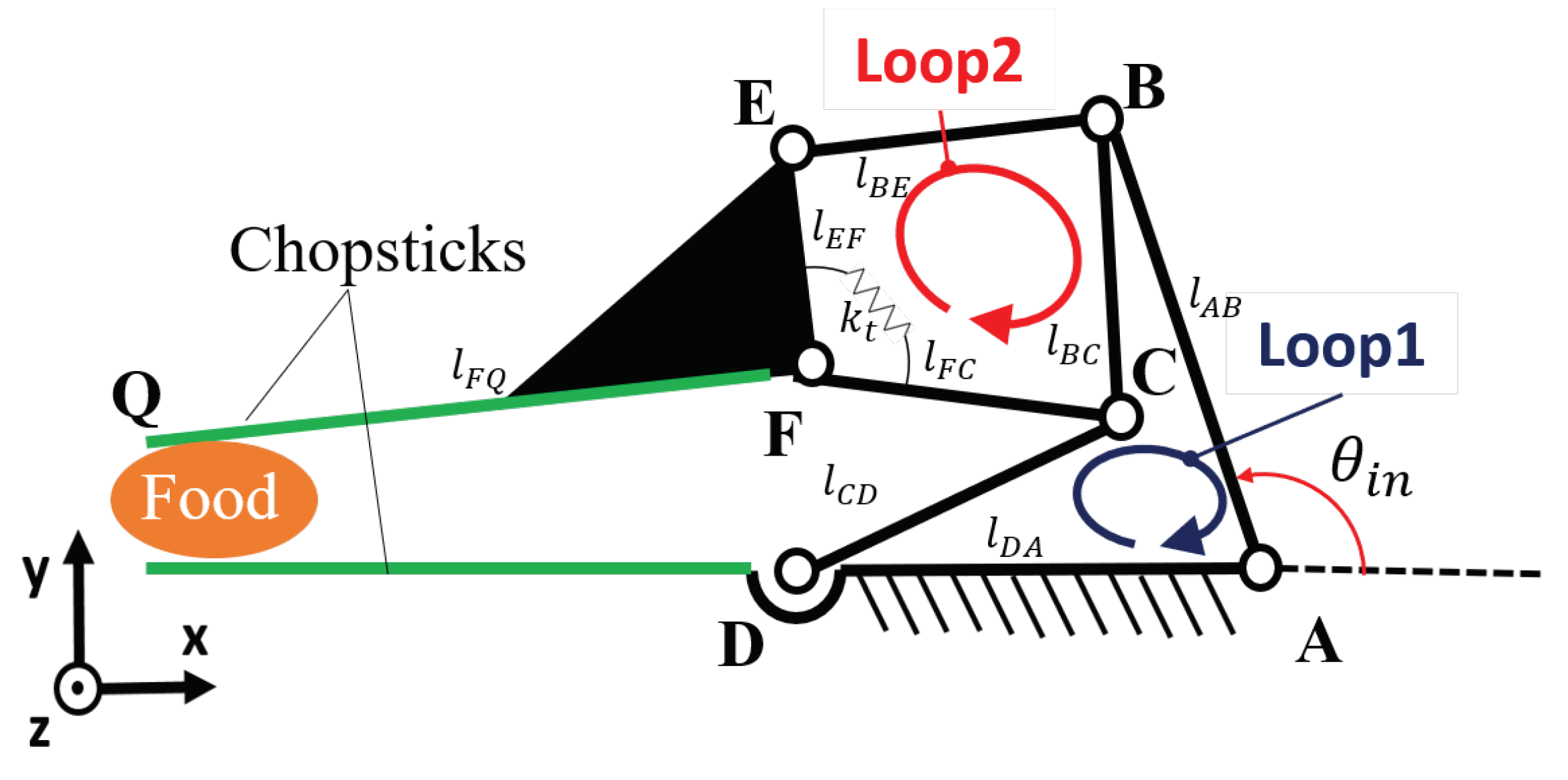
Figure 2 shows the proposed mechanism. It is a planar 2-DOF mechanism composed of two four-bar closed loops, ABCD (Loop 1) and BEFC (Loop 2). The degree of freedom of this mechanism is calculated while using Gruebler’s equation described as Equation (
1).
where,
N is the number of links, and
J is the number of joints, and
is the degree of the freedom of the joint. In this case, all of joints are revolute pairs, thus
.
A pair of chopsticks is comprised of the base link AD with an extension and the coupler link FQ. All joints A to F are revolute-type, and only one of them, A, is actuated. Thus, te entire mechanism is under-actuated [
16,
17,
18,
19], but, since a torsion spring is attached at joint F, connecting the links FC and FE, its configuration is statically determined once the actuator’s input angle and external force on the end-effector (gripping force between chopsticks) are specified. When the chopsticks are not in contact with the food and no external force is applied, joint F is considered to remain at a neutral angle determined by the torsion spring, and the mechanism’s configuration is thus only determined by the input angle of the actuator. In contrast, when the chopsticks contact with the food, the shape of Loop 2 changes according to the deformation of the torsion spring due to a deterministic motion of Loop 1. Thus, Loop 1 generates the path of the tip of the chopsticks part, and Loop 2 regulates the gripping force with an object to be grasped. Therefore, the gripping force is adjustable by the position control of the driving motor, and each of the loops can be separately designed. Additionally, the proposed mechanism has a feature to grasp an object at the tip part and adjust its force with deformation of the torsion spring, while the other underactuated mechanisms, such as [
16,
17,
18,
19], were designed to wrap around an object to grasp it.
5. Grasp Planning Considering the Characteristic of the Mechanism
This section addresses grasp planning utilizing the feature of the mechanism, that is the mechanism can change the contact force with changing the contact position. The proposed grasp planning derives the input motor angle and the contact position to grasp up food in order to realize a simple control system.
5.1. Grasp Planning Algorithm
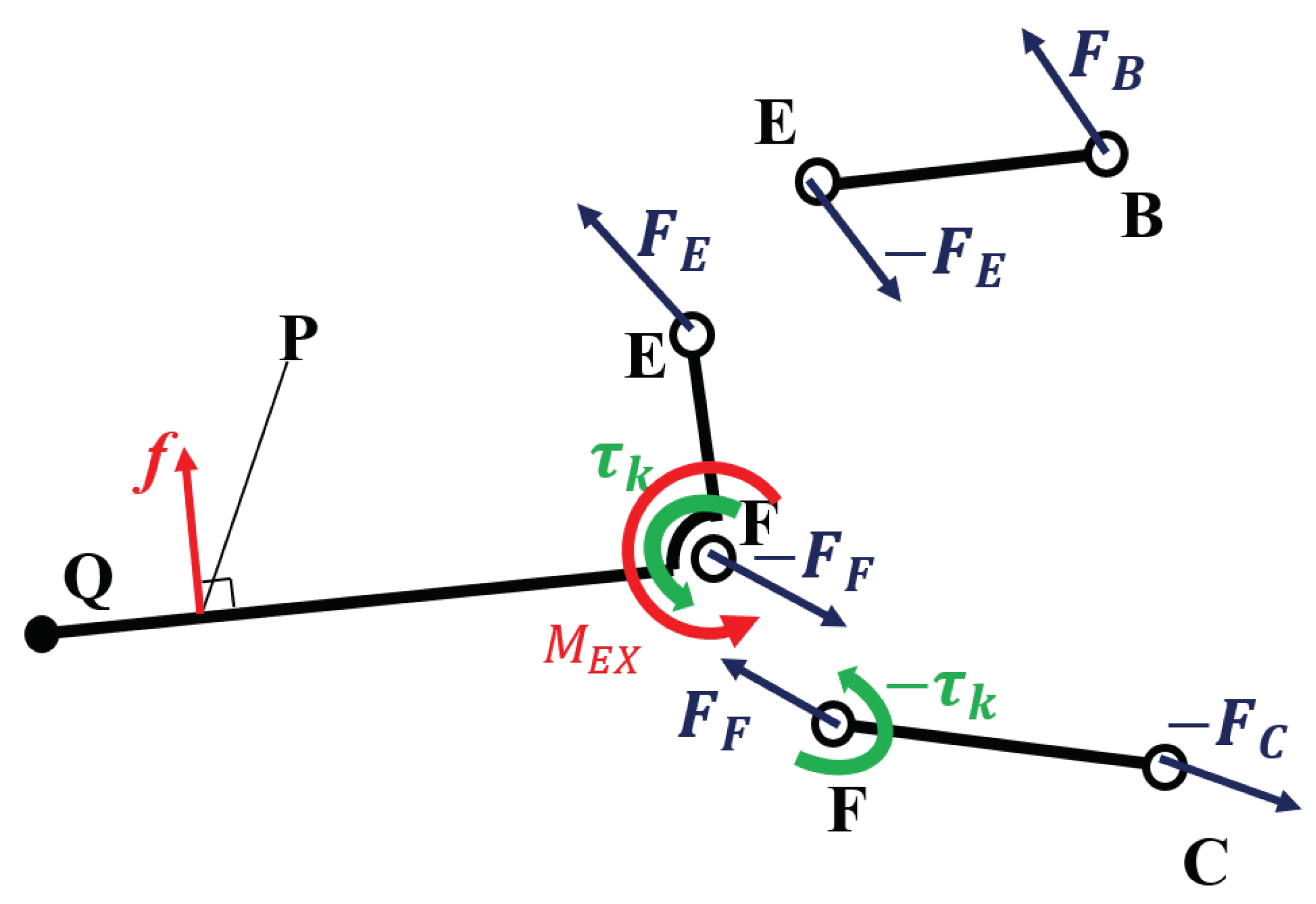
The grasping of the chopstick-type gripper is modeled in order to know how much force is needed to pick up a food. The proposed mechanism is a planar mechanism, and the gripping of the target food is established by the equilibrium of forces between the gravitational force of the food and the friction forces from the gripper, as shown in
Figure 9. Subsequently, the equilibrium of the forces is described as Equations (
9) and (10) under the assumption that the two friction forces
are equal. In this case,
m,
g,
are set as the mass of the food, the gravitational acceleration, and the coefficient of static friction, respectively.
Thus, to pick up the food, the gripping force is described as Equation (
11) with the safety factor
for the maximum friction force.
In the following, the gripping force to pick up food will be obtained by the position control of the driving motor of the gripper mechanism and the end-effector of the manipulator in order to implement a simple control system, and the grasp planning is proposed based on it. In other words, the grasp planning aims to obtain the required force in order to pick up the food without feedback control.
The grasp planning algorithm is proposed from the results obtained from the analysis. In the paper, the grasp planning is regarded as the planning to decide the contact position and the input motor angle for the gripper to grasp the food.
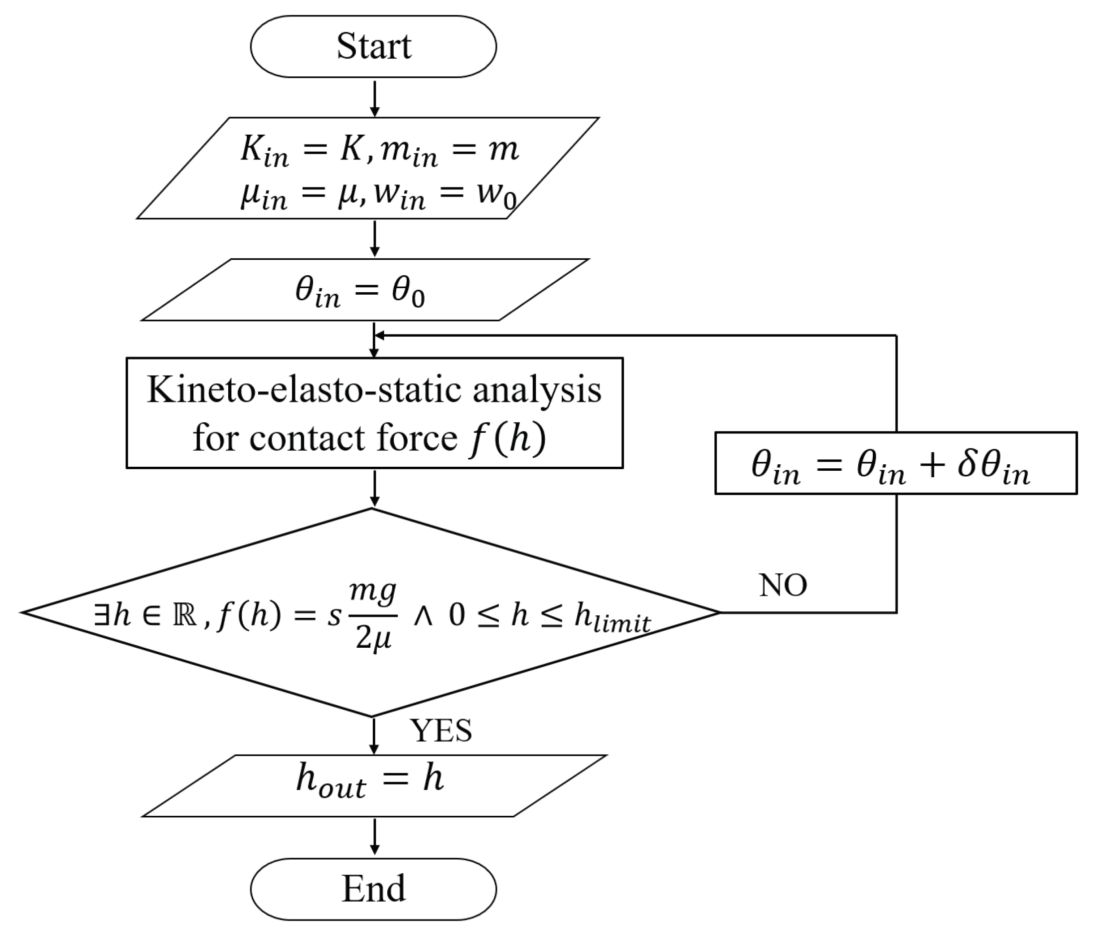
Figure 10 shows the algorithm of the proposed grasp planning. For the grasp planning, it is considered that the magnitude of the contact force
monotonically increases with respect to the contact position
h when the stiffness of the food is known, as
Figure 8 shows. Additionally, the range of contact point is set as
. The procedure of grasp planning is summarized, as follows.
For the given
,
K,
m and
, the gripping force to pick up food,
, is calculated by Equation (
11).
The motor input angle is given, and the function is derived using the analysis.
It is determined if the solution h exists, which satisfies in the assumed contact range (). When the solution h exists in the range, the h is obtained by solving the equation . When the solution h does not exist, the motor input angle is updated and the calculation goes back to step.2.
5.2. Case Study of the Grasp Planning
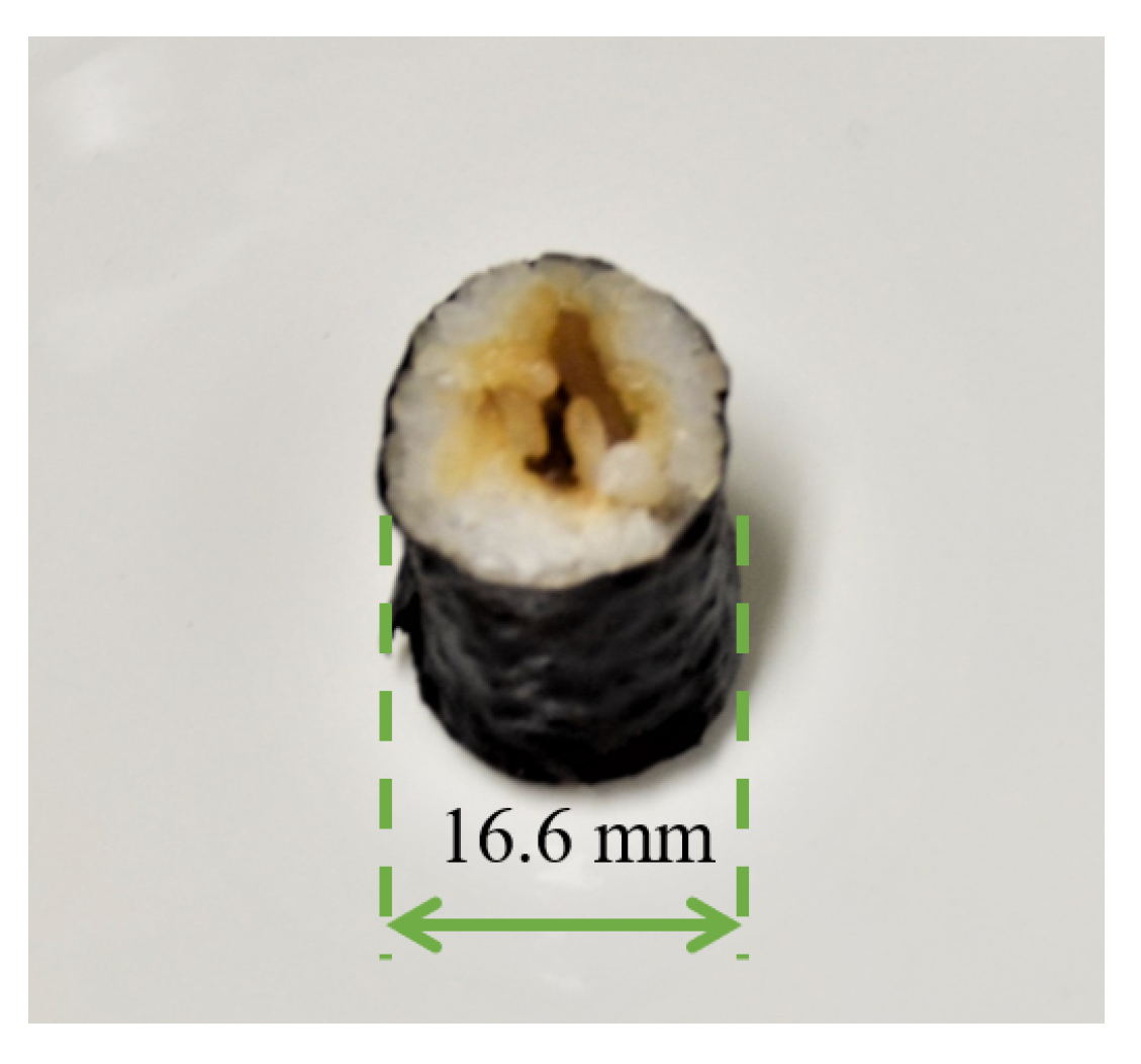
Case studies to decide the input motor angle and the contact position by the proposed grasp planning are described. For the examples, the safety factor is set as , the update value of the input motor angle is set as , and the range of the contact is set as .
(case.1) As
From Equation (
11), the required force for grasping is
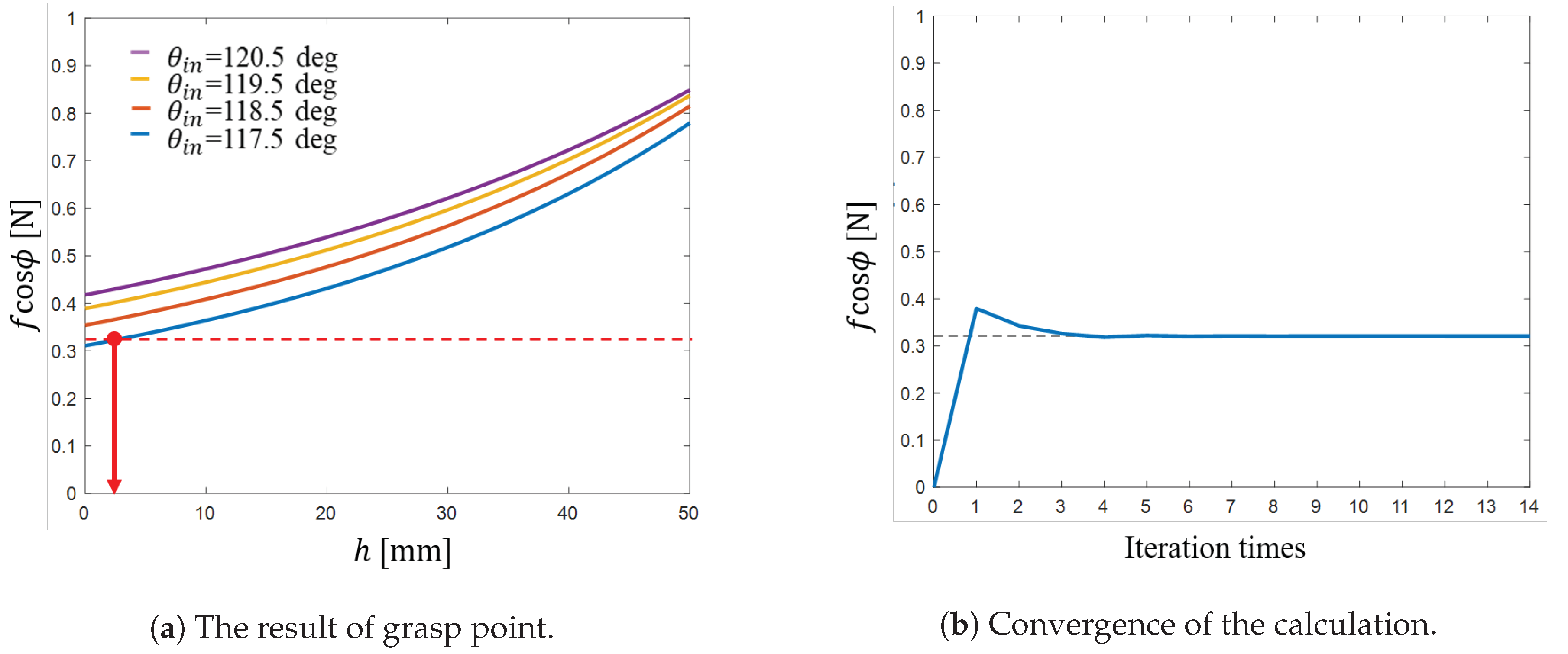
. From
Figure 11a, when the input motor angle is
,
h which satisfies
exists, and the solution is
.
Figure 11b shows that the calculation is converged.
(case.2) As
From Equation (
11), the required force for grasping is
. From
Figure 12a, when the input motor angle is
,
h, which satisfies
does not exist, then the input motor angle is updated. From
Figure 12a, when the input motor angle is
, the
h which satisfies
exists, and the solution is
.
Figure 12b shows that the calculation is converged.
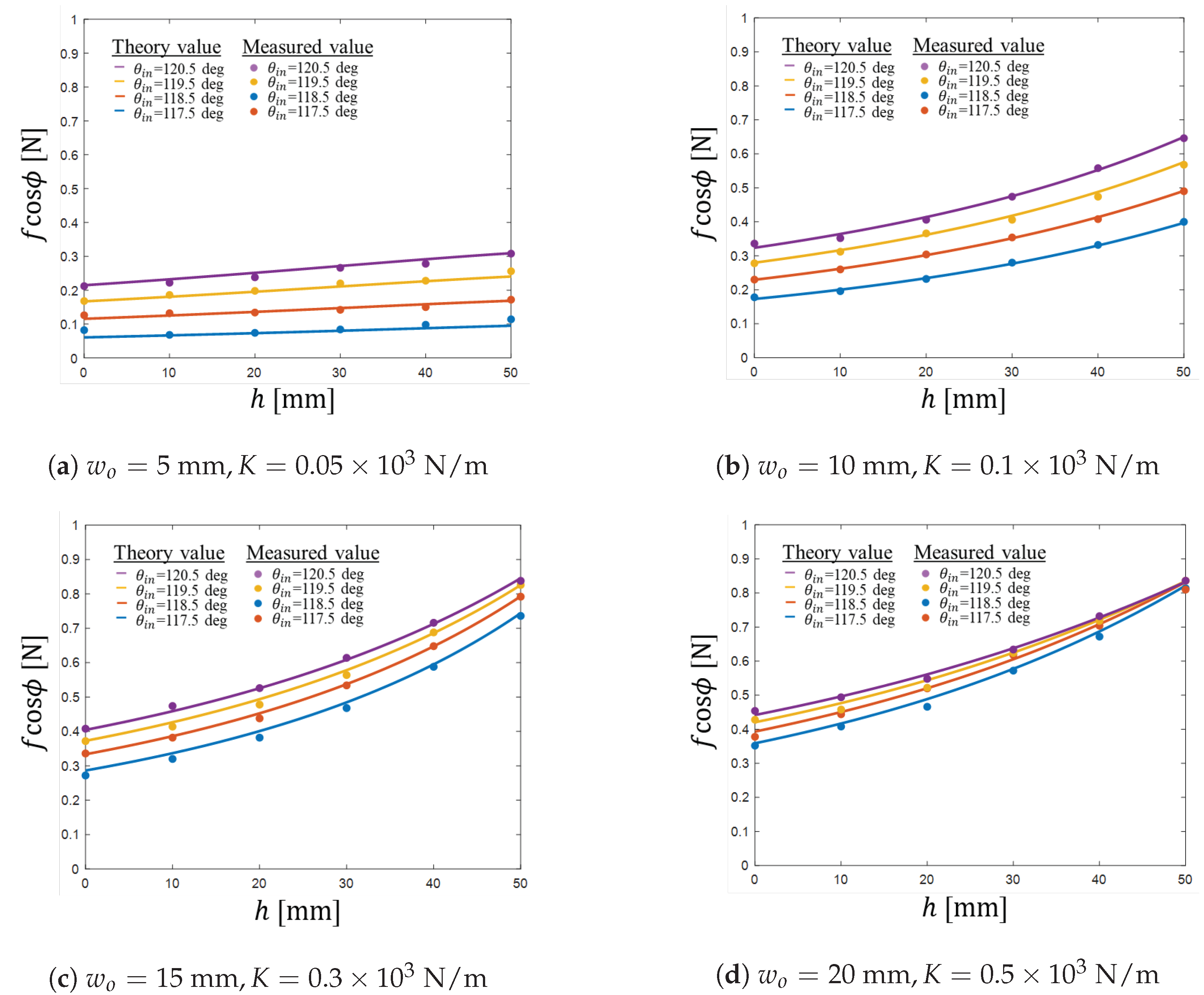
In this paper, it is assumed that the parameters of the food such as dimensions, mass and stiffness are obtained from the database based on the measurement by the vision system. Then, the error of these parameter values is inevitable. Here, let us investigate the effect of the error of stiffness value, which seems the most difficult to get precise value among the parameters, on the gripping performance through examples. The error of the stiffness K is considered under an assumption that its value includes maximum error by of its nominal value. Two cases of nominal stiffness values: and for , and are considered. Taking into consideration the maximum error in stiffness, we obtained that the contact forces vary between (−0.94%) and () (nominal value: ) for , and between (−3.96 %) and () (nominal value: ) for , respectively. From these results, it is known that the sensitivity of the stiffness error on the contact force error is low while the stiffness for soft food is more sensitive to the contact force than for hard food. Therefore, it can be said that the proposed mechanism can achieve a stable gripping under the existence of the estimated stiffness value error. In the case where a quite sensitive force control is required to handle a very delicate food, in order to avoid hurting the food, a feedback control system, such as an impedance control system, may be applied. Even in such a case, a low-cost control system may be constructed by adding an angular displacement sensor at joint F to measure the spring force, which is based on the advantage of the proposed mechanism.
7. Conclusions
In this paper, a chopstick-type gripper mechanism based on the concept of under-actuation and solely use of position control, which is capable of adapting its shape and contact force according to size and stiffness of target foods, was proposed. Modeling of the mechanism, including the contact with target food having stiffness, has been done in order to design a practical gripper. Based on this model, an analysis scheme based on iterative calculations of kineto-elasto-static analysis has been formulated and shown to be improved through comparison with the other analysis scheme of our previous work from the point of view of the computational efficiency. Based on the result of analysis, it is revealed that the proposed mechanism is able to adjust its contact force according to the size and stiffness of target foods, and that the gripper mechanism is able to change its gripping force according to the contact position with the target object, which is utilized for the grasp planning that determines the contact position suitable for its grasping. Through examples, it has been revealed that the contact force of the proposed mechanism is less sensitive against the stiffness error. While using the gripper prototype, the contact force was measured by a force gauge with an attachment having a spring with changing the contact point with a linear guide. From the result of the experiment, the modeling of mechanism in the kineto-elasto-static analysis and the mechanism’s feature that the mechanism can change its contact force according to the size and stiffness and the contact position with the object was validated. Additionally, using the 6-DOF robot arm, the grasping test of a real food was conducted utilizing the proposed grasp planning. The gripper was able to lift up the food using the input parameters obtained by the grasp planning, and the feasibility of the grasp planning was confirmed. For future works, experiments to grasp other kinds of food will be carried out in order to decide the scope of the application of the gripper. Additionally, a control system utilizing some feedback signal without implementing complex and expensive instruments based on the impedance control will be introduced to achieve more stable and appropriate gripping a wide variety of foods. Furthermore, in addition to the gripper mechanism and its control system, future work includes the design of the gripper with different shape of the end-effector for more practical development.

 ,
, 


