Article

NOHAS: A Novel Orthotic Hand Actuated by Servo Motors and Mobile App for Stroke Rehabilitation

by
Ebenezer Raj Selvaraj Mercyshalinie
1,2,
Akash Ghadge
1,
Nneka Ifejika
3 and
Yonas Tadesse
1,2,*
1
The Humanoid Biorobotics and Smart Systems Lab (HBS Lab), Department of Mechanical Engineering, University of Texas at Dallas, 800 W Campbell Rd, Richardson, TX 75080, USA
2
Bioengineering Department, University of Texas at Dallas, 800 W Campbell Rd, Richardson, TX 75080, USA
3
Department of Physical Medicine and Rehabilitation, Department of Neurology, UT Southwestern Medical Center, 5323 Harry Hines Blvd, Dallas, TX 75390, USA
*
Author to whom correspondence should be addressed.
Robotics 2023, 12(6), 169; https://doi.org/10.3390/robotics12060169
Submission received: 10 September 2023 / Revised: 23 November 2023 / Accepted: 5 December 2023 / Published: 8 December 2023
(This article belongs to the Special Issue AI for Robotic Exoskeletons and Prostheses)

Abstract

:
The rehabilitation process after the onset of a stroke primarily deals with assisting in regaining mobility, communication skills, swallowing function, and activities of daily living (ADLs). This entirely depends on the specific regions of the brain that have been affected by the stroke. Patients can learn how to utilize adaptive equipment, regain movement, and reduce muscle spasticity through certain repetitive exercises and therapeutic interventions. These exercises can be performed by wearing soft robotic gloves on the impaired extremity. For post-stroke rehabilitation, we have designed and characterized an interactive hand orthosis with tendon-driven finger actuation mechanisms actuated by servo motors, which consists of a fabric glove and force-sensitive resistors (FSRs) at the tip. The robotic device moves the user’s hand when operated by mobile phone to replicate normal gripping behavior. In this paper, the characterization of finger movements in response to step input commands from a mobile app was carried out for each finger at the proximal interphalangeal (PIP), distal interphalangeal (DIP), and metacarpophalangeal (MCP) joints. In general, servo motor-based hand orthoses are energy-efficient; however, they generate noise during actuation. Here, we quantified the noise generated by servo motor actuation for each finger as well as when a group of fingers is simultaneously activated. To test ADL ability, we evaluated the device’s effectiveness in holding different objects from the Action Research Arm Test (ARAT) kit. Our device, novel hand orthosis actuated by servo motors (NOHAS), was tested on ten healthy human subjects and showed an average of 90% success rate in grasping tasks. Our orthotic hand shows promise for aiding post-stroke subjects recover because of its simplicity of use, lightweight construction, and carefully designed components.

1. Introduction

Stroke ranks as the second leading cause of death globally, accounting for approximately 5.5 million deaths annually. The significant impact of stroke extends beyond its high mortality rate, as up to 50% of survivors face chronic disabilities. Consequently, stroke emerges as a disease of considerable public health significance, carrying substantial economic and social consequences. The public health burden associated with stroke is anticipated to escalate in the coming decades due to demographic shifts, especially in developing nations [1].
Activities of daily living (ADLs) are essential daily self-care tasks performed by individuals, including feeding, grooming, dressing, toileting, and mobility. Hand orthoses are assistive devices that aid in improving hand function, grasp strength, and dexterity, which allows individuals with hand impairments and spasticity to perform ADLs independently.
The development and testing of hand orthotic devices have been reported in many academic journals and conference proceedings, where innovative approaches have been explored, such as the use of shape memory alloys (SMAs), twisted and coiled polymer (TCP) actuators, and 3D printing technologies. The orthotic devices designed are personalized, portable, and aid in specific activities such as grasping and hand extension. The effects of hand therapy and rehabilitation involving orthoses on the independence of individuals in performing ADLs have been examined, underscoring the crucial role of hand function. They emphasize the importance of developing effective and personalized hand orthoses that aid in improving hand function and independence in performing ADLs for individuals with hand impairments [2,3,4,5].
Servo motors are used in hand orthoses for providing precise and smooth movements to the fingers and wrist. In an article by Dindorf and Wos in [6], an elbow orthosis with a bimuscular pneumatic servo drive which uses bioelectric signals for control is proposed. One key challenge in the integration of a bimuscular pneumatic servo drive using bioelectric signals within a virtual reality-based system lies in achieving seamless coordination and precision to ensure accurate and responsive control of the orthotic hand. Another issue of pneumatic systems for ADLs is portability. Cartagena et al. in [7] developed a multifunctional orthosis for hand rehabilitation based on virtual reality, which incorporates servo motors for finger flexion and extension. Megalingam et al. [8] designed a wearable hand orthotic device for rehabilitation with multimode control and real-time feedback which also uses servo motors to provide precise movements to the fingers. Veale and Xie in [9] reviewed current and emerging actuator technologies for developing compliant and wearable orthoses, including servo motors. Gretsch et al. in [10] developed a novel 3D-printed robotic prosthetic for amputees which incorporates servo motors to provide precise finger movements. The use of servo motors in hand orthoses ensures precise and smooth movements, which are crucial for effective rehabilitation and assistance to individuals with hand disabilities [11]. Hence, we focus on servo motors in this paper.
In terms of interfaces, the combination of a brain–computer interface (BCI) and a robotic hand orthosis has shown potential for improving motor function in stroke patients [12]. BCIs use electroencephalography (EEG) or near-infrared spectroscopy (NIRS) to detect motor intention signals from the user’s brain and translate them into control signals for the servo motors that control hand orthoses. Studies evaluating the performance of BCI-driven hand orthoses showed promising results in stroke patients’ neurorehabilitation. Therefore, BCIs coupled with servo motors in hand orthoses could be an effective rehabilitation tool for stroke patients [13,14,15,16,17,18,19]. Challenges may arise in the harmonious synchronization of bioelectric signals and the precise actions of servo motors, necessitating careful optimization to ensure seamless functionality and enhance the overall efficacy of the orthotic hand system. Advanced brain–computer interfaces (BCIs) are undoubtedly impressive. However, we believe that utilizing a mobile app controlled via Bluetooth to operate hand orthoses simplifies the actuation process, makes it more accessible, and transforms it into a versatile tool for both rehabilitation and as an assistive device.
The myoelectric concept is a technology used to control a prosthesis or orthosis using the electrical signals generated by muscles during contraction. Several studies have explored the use of myoelectric hand orthoses in different applications, including stroke rehabilitation, Duchenne muscular dystrophy, and spinal cord injury. A myoelectric orthosis typically consists of sensors that detect the electrical signals generated by the muscles, which are then translated into movement commands for the servo motor that actuates the orthosis. The servo motor, in turn, produces the desired movements of the orthosis, allowing the user to perform a range of functions with their affected limb. The studies reviewed here describe the design, development, and use of custom myoelectric elbow–wrist–hand orthoses for upper extremity paresis and loss of function in chronic stroke, as well as the use of electromyography to characterize muscle activation in Duchenne muscular dystrophy. The development of 3D-printed myoelectric hand orthoses for patients with spinal cord injury and the importance of user-centered design methodology are also discussed. Overall, the myoelectric concept has shown promise in improving upper limb function and quality of life for individuals with various neurological and muscular conditions [20,21,22,23,24].
The acoustic noise generated by servo motors can be a significant problem in various applications, such as cost-effective systems. We emphasized noise measurement because the major problem of servo motor-based actuation is their noise and size. We quantified the noise level in such designs to make sure this variable is quantified. To reduce the noise level, different techniques have been proposed in the literature. One approach is to use dual servo loops and digital filter implementation, which can provide ultraprecision positioning. Torsional oscillations can also contribute to the noise level, and the suppression of these oscillations is necessary in high-performance speed servo drives. In the case of controlling traveling-wave ultrasonic motors, pulse width modulation techniques can be used. Overall, reducing noise levels in servo motor systems can improve their performance and reliability in various applications. Velocity control of servo motor systems using an integral retarded algorithm can control the servo motor’s velocity smoothly and accurately. In general, reducing noise in servo motor systems involves identifying and addressing the sources of vibration, optimizing control algorithms, and ensuring proper system design and maintenance. Techniques such as vibration analysis, frequency analysis, and signal processing can also be used to identify and quantify the sources of noise [25,26,27,28,29,30,31].
The use of soft robotics in rehabilitation for stroke and related disorders has been explored in recent studies [32,33]. Soft robotics allow for the development of lightweight and adaptable devices that can conform to the user’s body, providing a more natural and comfortable fit. A challenge in implementing soft robotics in orthotic hands is achieving the necessary balance between flexibility and precision to effectively mimic natural human movements while providing adequate support and functionality. Using cotton gloves and evaluating users’ preferences could be a much better option than using soft elastomeric materials. In a bioinspired soft robotics study, researchers discuss the selection of materials and actuation methods for creating soft robotic devices. In another study, “A helping hand”, the integration of optical strain sensors and electromyography (EMG) control in a soft orthosis for hand rehabilitation is explored. These studies demonstrate the potential of soft robotics in developing effective rehabilitation devices for stroke and related disorders [34,35]. Our device, NOHAS, incorporates the soft robotic concept using fabric gloves.
Stroke rehabilitation can be conducted using various approaches such as virtual task-specific training guided by a wearable robotic orthosis (UL-EXO7), actual task-specific training guided by a physical therapist, and spring-assisted orthosis training. Home-based technologies have also been studied for stroke rehabilitation. In all these approaches, the aim is to improve the motor function of stroke patients through repetitive training and assistance provided by various technologies or therapists [36,37,38]. These technologies and approaches can help stroke patients to regain their strength, coordination, and mobility, and ultimately improve their quality of life. This is the goal of the design of NOHAS, but the construction of the devices mentioned above could be difficult and involve expensive components.
Spinal cord injuries, traumas, aging, and strokes are significant contributors to arm impairment and chronic disabilities, necessitating the development of robotic devices for rehabilitation and daily assistance. Surface electromyography (sEMG) control has gained prominence as an intention control method in these devices [39]. A review on control methods by Hameed et al. highlighted key sEMG control criteria such as muscle selection, channel count, and sensor types. Notably, sEMG-based control often faces challenges such as weak signals and abnormal muscle activation in stroke patients, necessitating supplementary control paradigms for effectiveness. In another prosthetic hand study [40], a hand known as FLUIDHAND III was shown to have enhanced functionality, cosmesis, and adaptive grasping, utilizing flexible fluidic actuators and myoelectrodes for pattern selection. A limitation in comparison to servo motor actuation is that the utilization of flexible fluidic actuators and myoelectrodes for pattern selection may pose challenges in achieving the same level of precision and force control needed for certain tasks. Additionally, 3D-printed transitional prosthetic hands offer cost-effective solutions to enhancing the range of motion, strength, and anthropometric variables for children with upper limb deficiencies [41]. Despite factors such as durability and environmental considerations, these prosthetic devices show potential for patients in developing countries who are looking for enhanced functionality and accommodative sizing for their forearm circumference [39,40,41,42].
Advancements in medical technology are addressing the challenging issue of hand mobility recovery in stroke therapy, as stroke severely affects hand and locomotor movement. Wearable devices, including EMG-controlled 3D-printed hand exoskeletons, are emerging as valuable tools. Hand exoskeletons help with gripping and can potentially aid in broader hand rehabilitation. Additionally, active hand exoskeleton technologies for rehabilitation, augmentation, and haptic applications are being reviewed, emphasizing specific requirements and challenges posed by the complex anatomy and biomechanics of the hand. The utilization of additive manufacturing, particularly in soft 3D-printed robotic hands, presents lightweight and cost-effective alternatives for robotics and prosthetics. These developments also extend to socially assistive robots (SARs), which can be used in public places. A systematic review of robot-aided upper extremity rehabilitation systems highlights the need for personalization, improved human–robot interaction, and lifelike environments to enhance the adoption of robot-based rehabilitation in clinical practice. EMG-controlled robots need to be used with a great amount of care. Also, EMG signals need significant signal processing and circuits for controlling hand orthoses. Raw EMG signals can be used but their accuracy is limited. An inherent challenge in EEG- and EMG-controlled orthotic hands, compared to mobile app-controlled servo motors, is fine tuning and precise controlling that impacts the intricacy of certain movements. Overall, these technological advancements hold promise for improving the quality of life and mobility of individuals with neurological and upper limb impairments [43,44,45,46,47,48].
In terms of software interfaces, in 2019, Lin et al. showed a rehabilitation device called Quality of Movement Feedback-Oriented Measurement System (QM-fOrMS), which was designed for individuals with chronic upper limb motor deficits to monitor the motor functions of stroke patients during hospital rehabilitation sessions. QM-fOrMS, developed in Buffalo, NY, USA incorporated cost-effective portable sensors, including an eTextile pressure-sensitive Smart Mat and Smart Can, along with a mobile device. It offered a personalized and adaptive upper limb rehabilitation program that includes unilateral and bilateral functional activities [49]. Another study known as SpECTRUM, shown in [50], was based on a smart object ecosystem inspired by the Action Research Arm Test and consisted of objects like a hand grasping monitor and an arm dynamic monitor equipped with various sensors to monitor finger pressure, position, orientation, movements, and tremors during manipulation tasks. These objects connect to an Android mobile application for data transmission and performance assessment, allowing therapists to evaluate upper arm motor abilities and adapt rehabilitation programs. Health care professional evaluations indicate the utility of the objects and visualization interfaces, while a preliminary study of stroke patients confirms their willingness to use the ecosystem during rehabilitation sessions due to its user-friendliness [49,50]. These two devices are like the functioning of NOHAS but involve user interfaces for making the rehabilitation process easy. Hence, we considered the user interface of the device in our design of hand orthosis.
With regards to innovation, a range of innovative approaches and designs for hand exoskeleton systems tailored for applications in rehabilitation and virtual reality interfaces have been presented in [51,52,53,54,55]. A team of researchers in [51] introduces a dual-cable hand exoskeleton system optimized for virtual reality scenarios, focusing on the measurement of finger joint angles and the implementation of force feedback. Additionally, an index finger rehabilitation system known as HandeXos-Beta (HX-β) is presented, which offers a finger–thumb exoskeleton solution for hand rehabilitation, with independent actuation of thumb movements and the incorporation of series elastic actuators (SEA) to enable precise torque control [52]. The control of this orthotic device is seamless and accurate. The research contributions mentioned above collectively advance the field of hand exoskeleton technology, benefiting applications in rehabilitation and virtual reality interfaces. Our device’s novelty is also in the unique features of NOHAS that will be discussed in this paper in detail in various sections.
This paper is organized as follows. As outlined, key advancements in hand orthosis and prosthetics have been explained in the introduction. The next section will introduce the design of a novel hand orthosis actuated by servo motors (NOHAS). Next, two studies on device characterization or testing are presented. The first one is non-human testing which involves evaluation of NOHAS as an effective orthotic device. Next comes human subject testing, which involved humans in experiments with approval from the Institutional Review Board (IRB). A conclusion and summary are provided at the end. An overview video of NOHAS is provided and can be found in the supplementary video (Supplementary Materials) at the following link: https://youtu.be/RtTiUP9PP94 (accessed on 6 December 2023).
The key limitations of the current solutions and technologies can be summarized with the following key points:
  • Limited precision and control: One key challenge in the integration of hand orthoses based on pneumatic servo drives using bioelectric signals lies in achieving seamless coordination and precision to ensure accurate and responsive control of the orthotic hand. Bioelectric-based control like EEG- and EMG-based control often faces challenges, such as weak signals and abnormal muscle activation in stroke patients, necessitating supplementary control paradigms for effectiveness. An inherent challenge in EEG- and EMG-controlled orthotic hands, compared to mobile app-controlled servo motors, is fine tuning and precise control, which impact the intricacy of certain movements;
  • Acoustic noise, size, and cost: Many hand orthosis systems utilizing servo motors generate significant acoustic noise, which is a drawback in various scenarios, especially those requiring cost-effective and quiet operations. The noise level should be determined as it may impact user comfort and acceptance. This necessitates studying and overcoming the challenges in undesired acoustic noise in medical devices. Some hand orthoses are very expensive and unaffordable;
  • Limited adaptivity and individual needs: Some hand orthosis devices may lack adaptability to the specific needs and preference of individuals. The one-size-fits-all approach may not help to meet diverse requirements. Soft robotics can be a solution for fitting various groups. A challenge in implementing soft robotics in orthotic hands is achieving the necessary balance between flexibility, adaptability, and precision to effectively mimic natural human movements while providing adequate support and functionality.

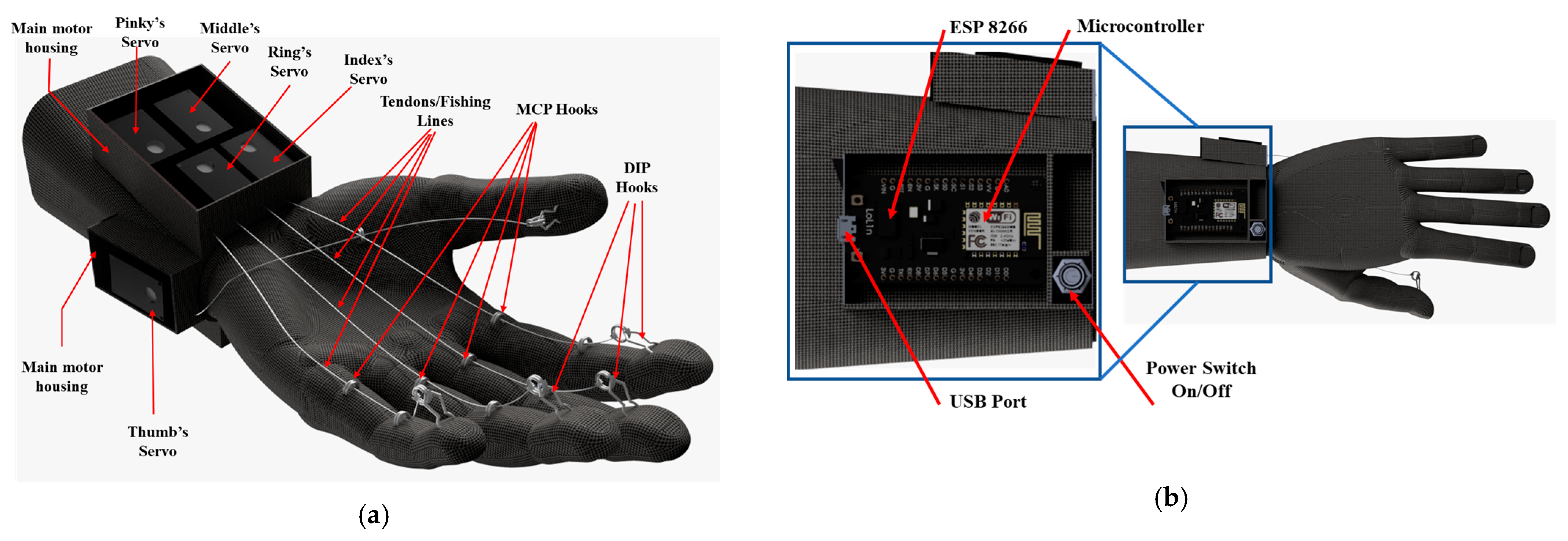
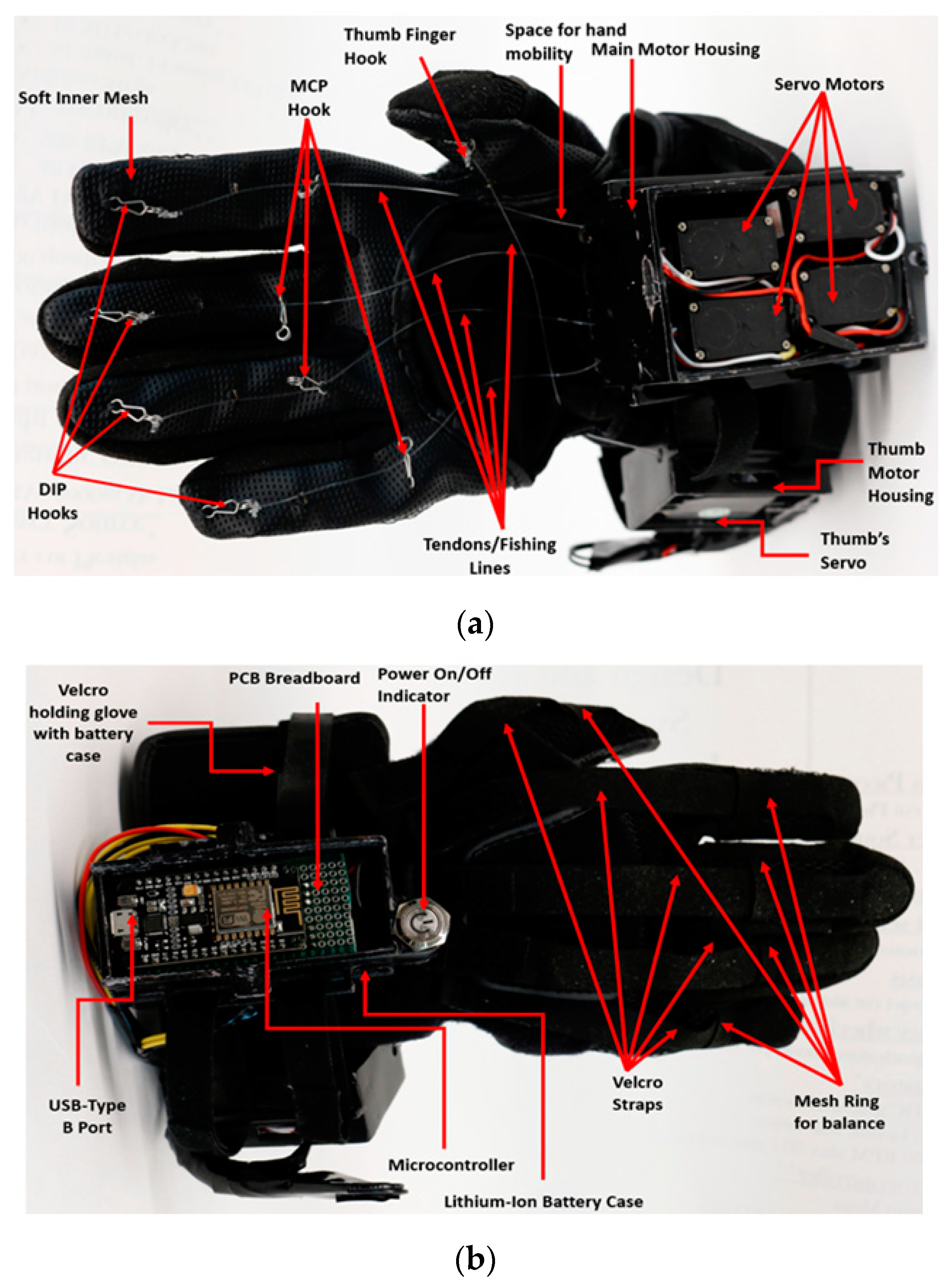
2. Design and Components

The main requirements of the design of our hand orthosis are the following: (1) lightweight—less than 500 g including battery, (2) low profile—fits average adult hand size (breadth 190–200 mm) with adjustable features, (3) inexpensive—material cost USD ~400, (4) actuated by simple wireless interface—for in-house operation, (5) untethered connection—powered on board by a battery, and (6) essential for ADLs as well as rehabilitation. Recently, these design specifications and other aspects were discussed in a review article [56] and we suggest it to readers for more detail. In the design of this hand orthosis, we brainstormed different ideas, and a group of students from a senior design team and graduate students worked on this collaboratively, supervised by the principal investigator from the concept stage to final development. Our final model is shown in Figure 1, and we evaluated the functionality mainly using a standard ARAT kit. The design of the hand orthosis consists of a few components: casing, fabric glove, velcro straps, tendons, servo motors, rechargeable battery, microcontroller, and a cell phone driver app. Servo motors are commonly used as actuators due to their unparalleled precision and control. Their ability to provide accurate and repeatable movements makes them ideal for applications requiring fine-tuned motion, such as in robotics, automation, and orthotic devices. Servo motors offer precise angular positioning and speed control, ensuring a reliable and controlled execution of tasks. Their closed-loop feedback systems enable real-time adjustments, enhancing overall performance. Additionally, servo motors are versatile, capable of handling various loads and operating conditions, making them an excellent choice in applications where precision and reliability are paramount. They have higher energy efficiency than other smart materials and can be operated for longer periods using rechargeable batteries. The CAD model of NOHAS is shown in Figure 1a and the back is shown in Figure 1b. The model was developed using SolidWorks (2022) software while the rendering was created using Autodesk Fusion 360 (V.2.0.15995). Each finger is operated by a fishing line which is connected to the tip of the finger with the help of a distal interphalangeal (DIP) joint hook, while the other end is attached to a corresponding servo motor. The fishing lines are guided with the help of metacarpophalangeal (MCP) joint hooks; each finger has two such hooks.

2.1. Materials Used in Construction

Casings: There are three major casings in our hand orthosis, namely (1) main motor housing, which has four servo motors that sit on the bottom of the user’s wrist; (2) thumb motor housing, which has one motor frame on the right side of the user’s wrist, and (3) final motor housing, which has one microcontroller and one battery power supply;
Microcontroller: An ESP8266 Wi-Fi microcontroller was selected based on its ability to transmit wireless communication, size, cost, and input/output capabilities. This model was obtained from Espressif Systems, Shanghai, China. The primary benefits of the ESP8266 are its web-friendly embedded technology and wireless capability. Other advantages include affordability, compact size, good speed, and processing power;
Rechargeable battery: A 3000 mAh lithium-ion rechargeable battery (Model Number 103665) is employed in the hand orthosis as a power supply. The battery is 10 × 36 × 66 mm in size and the weight is 47 g. It can actuate the servo motors for several hours (4 h of continuous use). We can also use an ESP8266 type B port by connecting it directly to a PC;
Servo motors: Servo motors (TowerPro SG92R and Sparkfun ROB-10189) with small 3D-printed PLA pulleys actuate the glove by pulling tendons that are connected to the fingertips and passing through guide wires. When the servo motors are actuated, they pull the tendons inside and cause the fingers to bend. The servo motors have position-sensing units that control the desired angles based on input. The ESP8266 Wi-Fi microcontroller is powered by a 9V battery, which also powers other components, including the servo motor;
Tendon: A 25 lb. monofilament fishing line that serves as the artificial tendon is connected to the glove and to the motor housing. The fishing line can spool around a pulley-style connection, which is attached to each motor. The fishing lines pass through holes in the housing along the palm area and are connected to the fingers at attachment points;
Velcro straps: For extra adjustability and customization to different users, the casings are joined by velcro straps; the wiring for the motors follows these straps. The region which is beneath the strap is rubberized to avoid the occurrence of slipping. This region also acts as a point of anchoring for the tendons and prevents the hyperextension of the DIP joint. These components can be securely attached to the fingers while reducing the amount of discomfort, hardness, and slipping due to foam padding and non-slip fabric straps. Mesh rings are used to maintain the finger’s equilibrium (Figure 2b);
Blynk app: Blynk is a smartphone or tablet device application that is used to operate the servo motors. It is an Internet of Things (IoT) app that allows users to control the device over the cloud. Blynk is a user-friendly app which can be customized and modified any time according to the user’s needs. The user will be able to set up specific control tasks or sequences to connect with the servo motors over the Wi-Fi chip using Blynk’s user-friendly interface;
Return elastic rubber bands: Elastics bands at the back of the glove serve as spring-returning mechanisms that direct the fingers to their original positions after actuation;
Glove: The fabric glove is made of cotton and wool. The glove increases the stability of ligaments and tendons in the wrist, which substantially increases the overall stability of the hand. Generally, the material of the glove is safe and does not cause allergies for most people, but it can be replaced as needed as some individuals may be allergic to wool;
Safety aspect in our design: NOHAS is safe and comfortable. In the design phase, we added all the movable parts within a casing so that the user will only be wearing a fabric glove on their hand. Later, throughout our human subject testing, no issues or complaints were raised regarding the wearability of the glove. In our IRB, we provided a clear explanation of the glove’s safety measures, highlighting that the use of compact and efficient servo motors ensures that there are no potential issues during finger flexion and extension. In the rare event that a user experiences even a minor discomfort, the device can be promptly deactivated, and the glove can be easily taken off the hand.

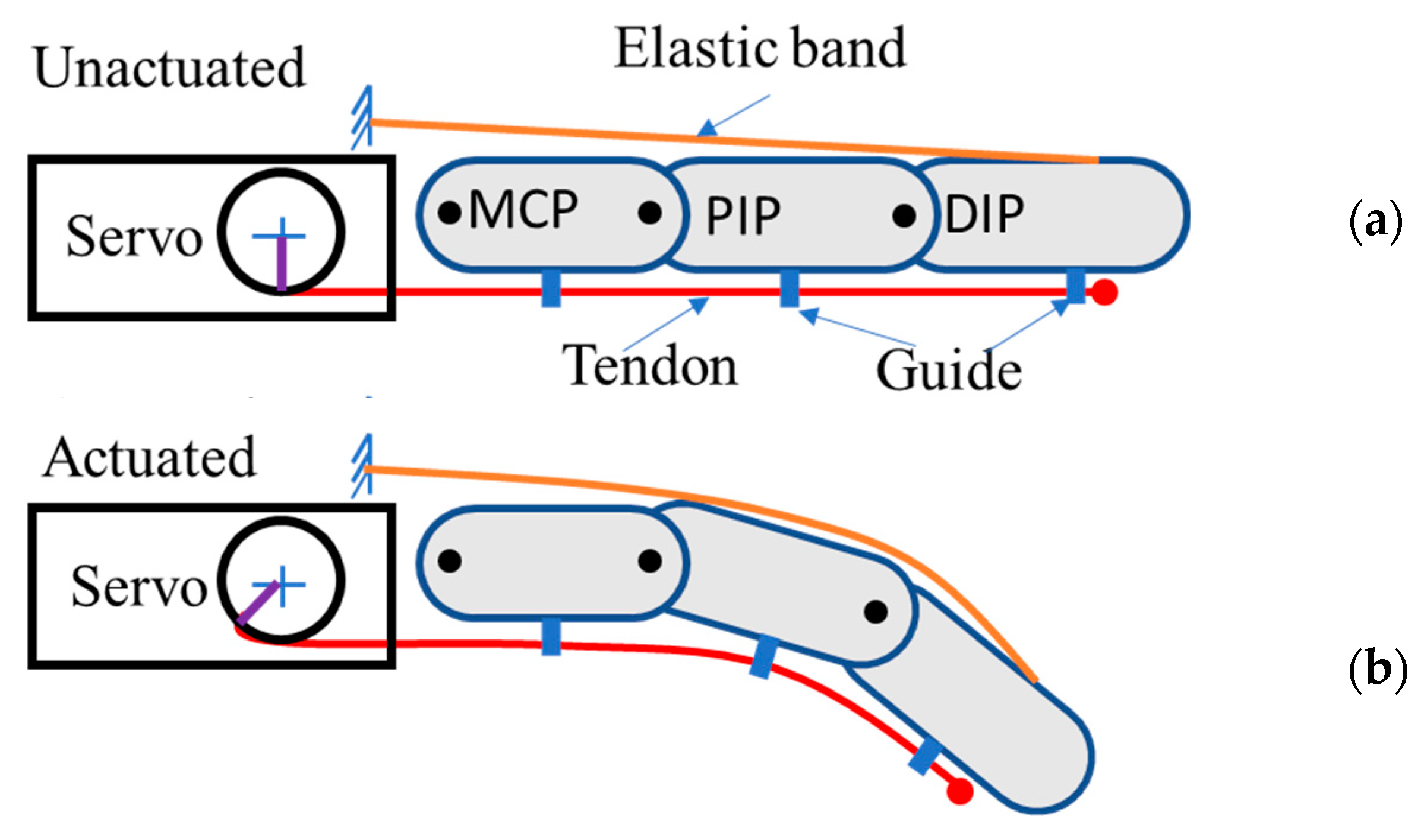
2.2. Prototype and Working Mechanism of the Hand Orthosis

The design comprises two independent parts in a right-handed configuration: the glove and electronics/motor housings. NOHAS is designed like other gloves used in hand rehabilitation. On the palmar side, active actuation occurs, and on the opposite side, a passive elastic band returns the finger back to its position. The thumb and each finger joint have two attachment points on the glove’s fabric. The housings for the motors and controller consist of three distinct shells that are designed and 3D printed with PLA+ material to be worn on the wrist like a “watch”. The primary motor housing, which contains four motors, is situated on the underside of the wrist. The thumb motor housing, which is on the right side of the wrist, contains just one motor. The prototype hand, when fully assembled, can be seen from the front and back sides as shown in Figure 2a,b, respectively.
The hypothesis of using servo motors for this application is that this technology provides a good combination of the desired attributes of a hand orthosis. Factors such as precise position, control, energy efficiency, compact size, and suitability for ADLs are among the key elements influencing our motor selection.
The working principle is shown in a schematic diagram in Figure 3a,b. When the servo motor is actuated to certain angles, the tendon connected to the guide structures will bend the fingers. The elastic band at the back of the glove returns the finger; at the same time, the servo motor should be actuated in the reverse direction to release the tendon.

2.3. Servo Motor Selection

Key properties were considered to select the proper servo motor for the design of the NOHAS hand orthosis. The servo motors must be able to rotate continuously at 360 degrees to be able to provide the necessary bending angle and torque to activate the fingers via the pulley system. An estimation based on data on men and women in their seventies says that their average gripping force is approximately 300 N [57]. If that is divided equally throughout all the fingers, then it will be 60 N per finger. NOHAS was designed using a TowerPro SG92R microservo and Sparkfun ROB-10189. SG92R has control arms and gears made of carbon fiber, which produces a torque of 2.5 kg-cm while weighing only 9 g. The SG92R can rotate about 180 degrees (90 degrees in each direction). Standard servo motors only operate inside a certain servo motor angle, typically 180 degrees. The ROB-10189 model has a stall torque of 2.2 kg-cm with 360-degree rotation. The servo motors are equipped with gears to reduce the motor speed and a potentiometer for position feedback. The motor may begin to vibrate and make noise if it is turned all the way to 0 or 180 because it is attempting to drive to an impassable position. It is preferable to either use it within the safety range or a usable range, such as 20–160 degrees. It is important to maximize the range because this results in a high stall current condition. This also has the potential to strip gears and it might lead to some unwanted damage to the motor. Because of the compact size, enhanced performance, and low-cost requirement of the glove, the RC servo motors discussed above were selected for the design. A dynamic equation using the Euler–Lagrange model for robotic or human fingers, including resistance and finger spasticity, can be expressed as [58]:
τ = M θ θ ¨ + V θ ,   θ ˙ + G θ + J θ T F  
where τ is the torque required to move the fingers, M θ is the mass and inertia matrix, which is an n × n matrix (n = 3 for the thumb and n = 4 for the other fingers), V θ ,   θ ˙ is the Coriolis and centrifugal terms, which is n × 1 vector, G θ is the gravity term, which is n × 1 vector. J θ is a Jacobian matrix that relates fingertip linear and angular displacement with joint velocity. F is applied force.
Equation (1) provides accurate modeling. However, it requires several variables and makes the selection of motors complicated. For simplicity, if we ignore gravity, Coriolis terms, and the resistance of fingers, the joint torque of the servo motors can be determined from a simple equation of force and offset distance from the following. A similar assumption was made in our previous analysis [59]:
  τ = F   r sin θ                                      
where τ is the torque required to move the fingers, F is the force needed to move the servo motor, r is the radius of the pulley/servo horn, θ is the bending angle of the finger/servo horn. Here, F = 60 N, r = 5 mm, and θ = 90, which yields τ = 2 kg-cm. Therefore, the minimum amount of torque required to actuate a finger with some safety factor will be approximately 2.6 kg-cm. Based on this calculation, all the servo motors for the hand orthosis are selected. Besides torque, size, weight, and cost are important properties of servo motors that determine the property of our orthotic hand.

3. Initial Characterization of NOHAS (Study 1)

In this section, we describe the methodology and experimental procedure for testing the orthotic hand by mounting it on a dummy hand. The experimental setup is shown in Figure 4a. The ESP 8266 chip’s Wi-Fi mode is automatically turned on when the button is turned on in NOHAS, showing a blue light in the ESP casing. There are some cases when the blue light does not turn on which means that the battery needs to be replaced. The battery must be checked and fully operational before testing the device. In the case where the battery does not work, we need to manually plug in the port from the ESP chip to the laptop’s port. Next, the mobile phone hotspot is turned on. In the list of available devices in our mobile phone, the ESP chip’s name is displayed, and we connect to it. After this, Arduino IDE is opened on the laptop and is connected to NOHAS’s ESP8266 chip port via a USB type-B cable. The next step is to verify the code in Arduino IDE. After the successful verification of the code in Arduino IDE, the code is uploaded to the ESP 8266 chip via the USB type-B cable. Generally, it takes less than a minute to successfully upload. The serial monitor displays that the connection is successfully established. The photograph of the real experimental setup is shown in Figure 4b, illustrating the device, laptop, cell phone, and a standard ARAT kit for grasping tasks [32]. The schematic diagram of the circuit was created using Cirkit Designer, and the codes were developed using integrated Arduino IDE. The circuit connections are shown in Figure 4c. Green wires represent positive connections, which are connected to the LED, resistor, all five servo motors, and ESP8266. Red wires establish a common ground for the circuit, ensuring proper voltage operation. Blue wires transmit the enable signal, allowing PWM signals to control the servo motors. LEDs indicate device status, and a resistor protects the LED. By actuating the servo motors according to a program in the mobile app, video recordings of the hand orthosis were taken and analyzed.

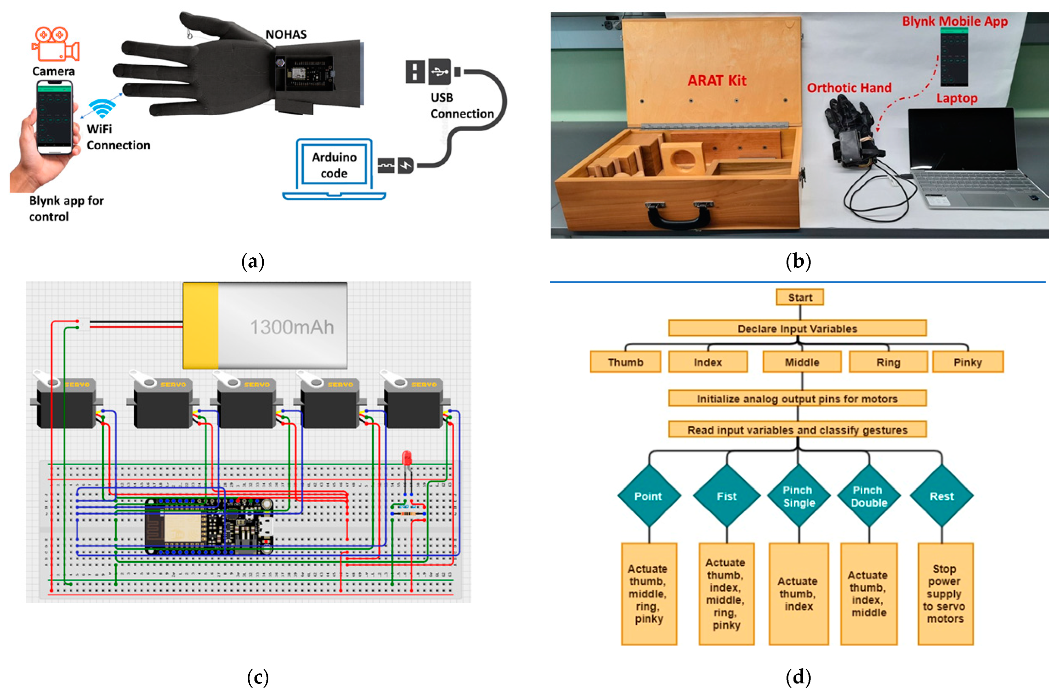
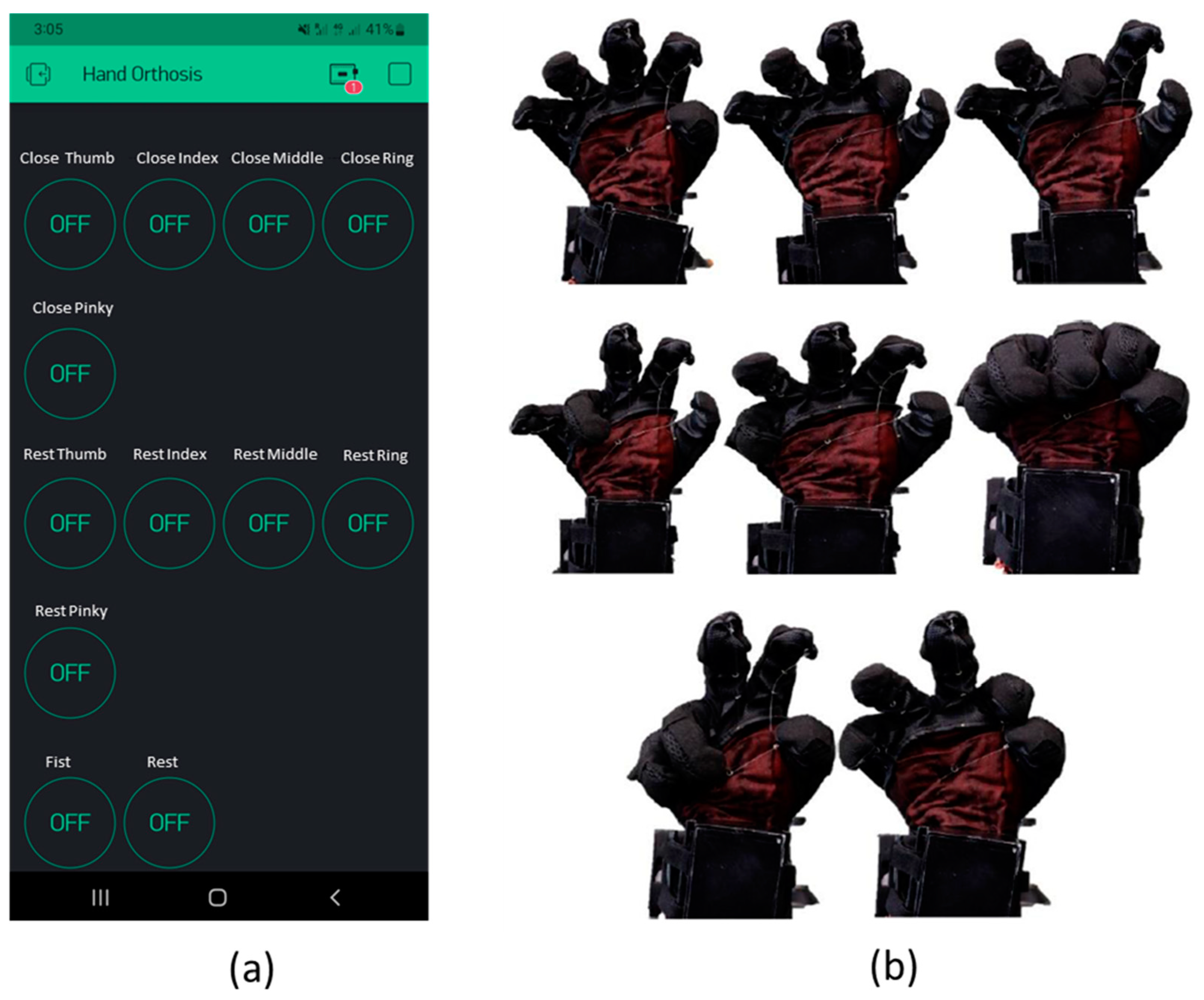
3.1. Basic Gesture Test

A basic gesture test was conducted using the Blynk mobile app by clicking the corresponding button in the program, as shown in Figure 5a. A dummy hand, which was made of silicone, was used to mimic a human hand and test the hand orthosis. For example, to actuate only the thumb, the button in the app is pressed once, then the servo motor will rotate approximately 30 degrees and move the finger. When the button is pressed again, it will move the thumb further by another 30 degrees. Typically, each finger is activated in three steps to complete full flexion. Finally, it will be set back to its position using the rest button. In ref. [60], researchers discussed two code states for a similar opening and closing orthotic hand. In our case, the code starts with declaring all the input variables. The input variables for the thumb, index, middle, ring, and pinky fingers are all presented separately, as shown in Figure 4d. Analog output pin initialization is carried out independently for each of the five servo motors. The next stage involves interpreting the input variables and categorizing the gestures.
As seen in Figure 5b, NOHAS was designed to execute various ADLs. The main reason for conducting this test was the evaluation of how efficiently the servo motors and pulleys worked. The test was conducted by mounting the hand orthosis on the dummy hand for different gestures. This test also provided us with experience with dealing with tangling of the tendon or fishing line. Also, since we quickly trigger two or three fingers at once and relax them, this test was crucial in determining how well NOHAS handled multitasking. Similar to any other exoskeleton with stiff components across the hand, researchers in [61] created and tested a device that restricts the use of compensatory grasps that do not involve the thumb. Battery drain must be considered as a key factor in this stage as multitasking quickly depletes the battery. As a result, we had to recharge the battery often. To characterize the device, some simple hand gestures, including pointing, pinching, the peace sign, closing the fist, etc., were performed to validate NOHAS. But after performing each of these gestures, we had to bring NOHAS back to the initial rest position where no special gestures or actions are performed. This prevents the fishing lines from being tangled inside the servo motors. The tendons might get stuck and might damage the hook. This may damage the soft clothing on top of NOHAS. Thus, the relaxation step is essential.

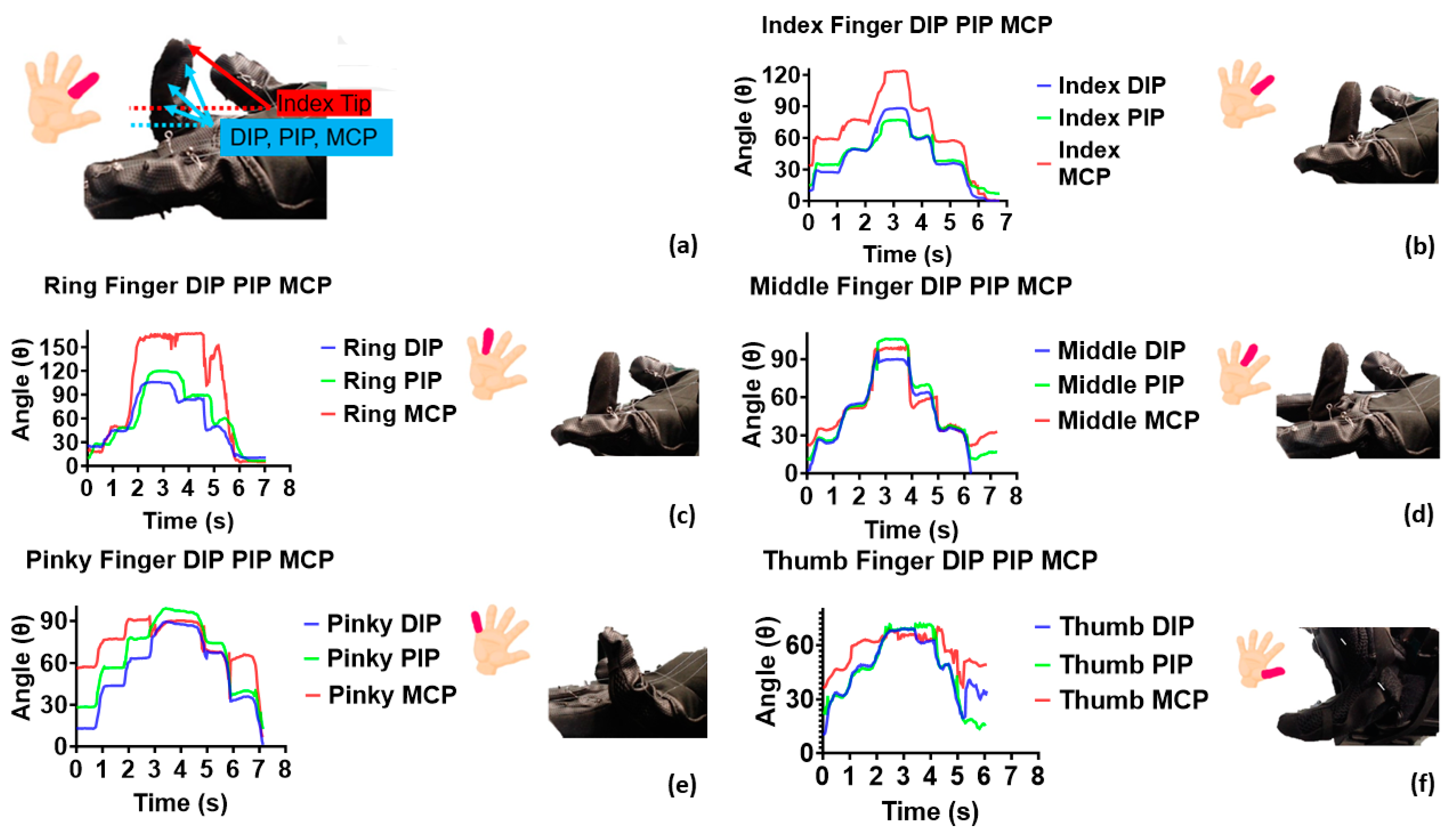
3.2. Agular Position Characterization and Maximum Angle Test

Using video tracker software, the bending angles for each DIP, MCP, and PIP joint were estimated using the following approach. Several commonly used apparatuses which are generally used to investigate the angular locations of orthotic devices include anatomically accurate hands, a high-speed Phantom Miro camera, a computer which can collect theNI-cDAQ data, a power supply, and a K-type thermocouple. These were used in Saharan et al.’s work [62]. Other researchers used a similar approach on stroke patients who were affected with mild to moderate motor function impairment [63]. A high-speed camera was not needed to capture the actuation of NOHAS as a regular camera was sufficient. After this process, the data were retrieved and analyzed.
In this work, we characterized NOHAS by following a few processing steps. The index finger was initially chosen. Actuation in response to servo motor motion was recorded by a camera and then loaded into the tracker software. The video was then paused and cropped inside the tracker software in such a way that the tracking started as soon as we could see the finger actuation happening in the uploaded video. The result is shown in Figure 6. Coordinate axes were added to the video. This was used in the tracker software to accurately position the starting point and angle inside the video. A calibration stick was added to the video to inform the software about the finger’s actual height. A point mass was positioned at the DIP joint, which is close to the tip of the index finger, to measure the DIP values. A similar process was conducted to automatically observe the other joints. The tracking was observed to be very smooth. Additionally, we can observe that the software appropriately plots the angle data vs. time.
The reference picture shown in Figure 6a explains the placement of the coordinate axes inside the tracker software. The procedure is the same for the index finger’s PIP joint as shown in Figure 6b, showing all the three joints of a finger. The same steps are then carried out for the remaining four fingers, as shown in (c) to (f). So, we obtained five angle vs. time data in total. The maximum extension and flexion range of the fingers must be taken into consideration to prevent overstretching or overfolding, which causes discomfort to the fingers. DIP, PIP, and MCP plots are essential for monitoring the behavior of any orthotic hand. We can see that there are three steps in the DIP, PIP, and MCP lines for each graph. Considering the blue line in Figure 6b, when the “index close” icon in the mobile app is pressed, the index finger angle value increases from 40 to 60 degrees from 0 s to 0.2 s. There is no actuation from 0.2 s to 1 s. From 1 s to 1.2 s, we can see the next actuation. Then, from 1.2 s to 2 s, there is no actuation or change in angle. The same concept holds for the relaxation phase. The relaxation steps are performed until the device returns to 0. The same procedure was followed for all the other four fingers.
Regarding characterization using video tracking, studies [64,65,66,67,68] employed wearable devices and exoskeletons with sensors like potentiometers or encoders to measure angular movements of DIP, PIP, and MCP joints. In contrast, our approach utilized Tracker software, employing video recordings to measure bending and visually document hand movements. Tracker has been used in many studies [69,70,71,72,73], where it effectively captured angular deflections of analog instrument pointers. Their collective findings underscore Tracker’s versatility, proving its value in cost-effective, straightforward experiments beyond mechanics, extending into various disciplines. The HBS lab group has successfully utilized Tracker software for characterizing dynamic motion, demonstrating its effectiveness in capturing angular motion [74,75,76].

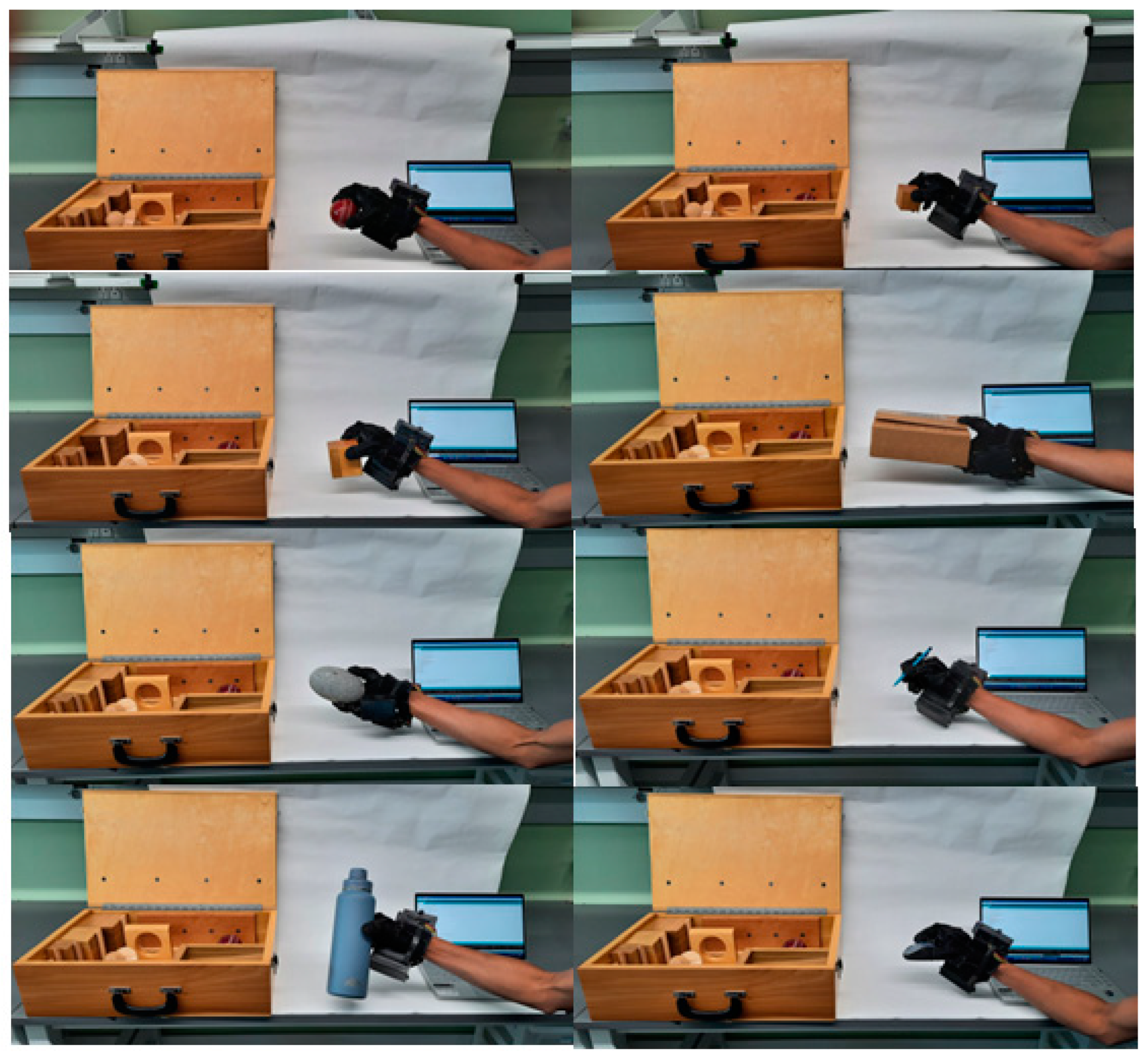
3.3. Standard Object Grasping Test

The grasping test was primarily conducted to measure the time duration NOHAS can hold the objects with a firm grip. This was performed by mounting it on one subject and grasping objects from the ARAT kit. Healthy humans rely on pinch and power grasping techniques, which primarily depend on the utilization of the thumb. On the other hand, stroke survivors without proper thumb function generally make use of the other four fingers primarily. They also sometimes forcefully place the thumb away against the backs of the fingers. This action helps them to squeeze an object between the fingers and the palm. The texture and weight of the objects were taken into consideration during selection. Figure 7 illustrates how various grips were used to grasp various objects while actuating NOHAS. As indicated in Table 1, daily use objects of varying weights, sizes, and forms were assessed. Many gripping positions, namely tripod, extension, transverse volar, spherical volar, diagonal volar, lateral pinch, five finger pinch, and pulp squeeze [77] were tried and their outcomes are shown in Figure 7. The various objects used in Figure 7, the weights of individual objects, texture, size, and effective holding for NOHAS are provided in Table 1. These grasping techniques gave us a clear understanding of human muscles and their capacity to grasp various items.

3.4. Variations in Finger Actuation Timing Test

The fingers of NOHAS were actuated and tested in a time interval of five, three, and one second, which are referred to as slow, medium, and fast, respectively. This test is like the test results shown in Figure 6, but here, the duration of actuation time is varied. First, the thumb was actuated and relaxed over a period of five seconds, resulting in slight movement from the initial position. After 5 s, the finger moved up a little bit more for the second actuation. In the third actuation, the finger was shown completely bent. This was a slow process. It was performed at the beginning to prevent the fishing lines from tangling and to watch if the device heats up. But, throughout the repeated actuation, there was no heating observed.
In a similar manner, all five fingers were gradually triggered over a period of five seconds. The thumb was triggered and actuated after three seconds in the next step. The second actuation happened a little bit quicker than the first. Like the prior phase, no obvious heating was noticed. The same procedure was followed for all the other four fingers. Finally, the thumb’s actuation was completed after a 1 s delay. This actuation interval is the quickest since the delay is observed to be just 1 s. The primary motor housing clearly heated up because the actuation was nearly constant. Occasionally, the entanglement of tendons was also observed. In such cases, the “resting button” in the app should be pressed, and the orthosis should be rested to release the tangling. Due to high actuation frequency, the Bluetooth connection occasionally experienced some connectivity issues. However, these problems were resolved once the actuation was carried out once every second without any lag.

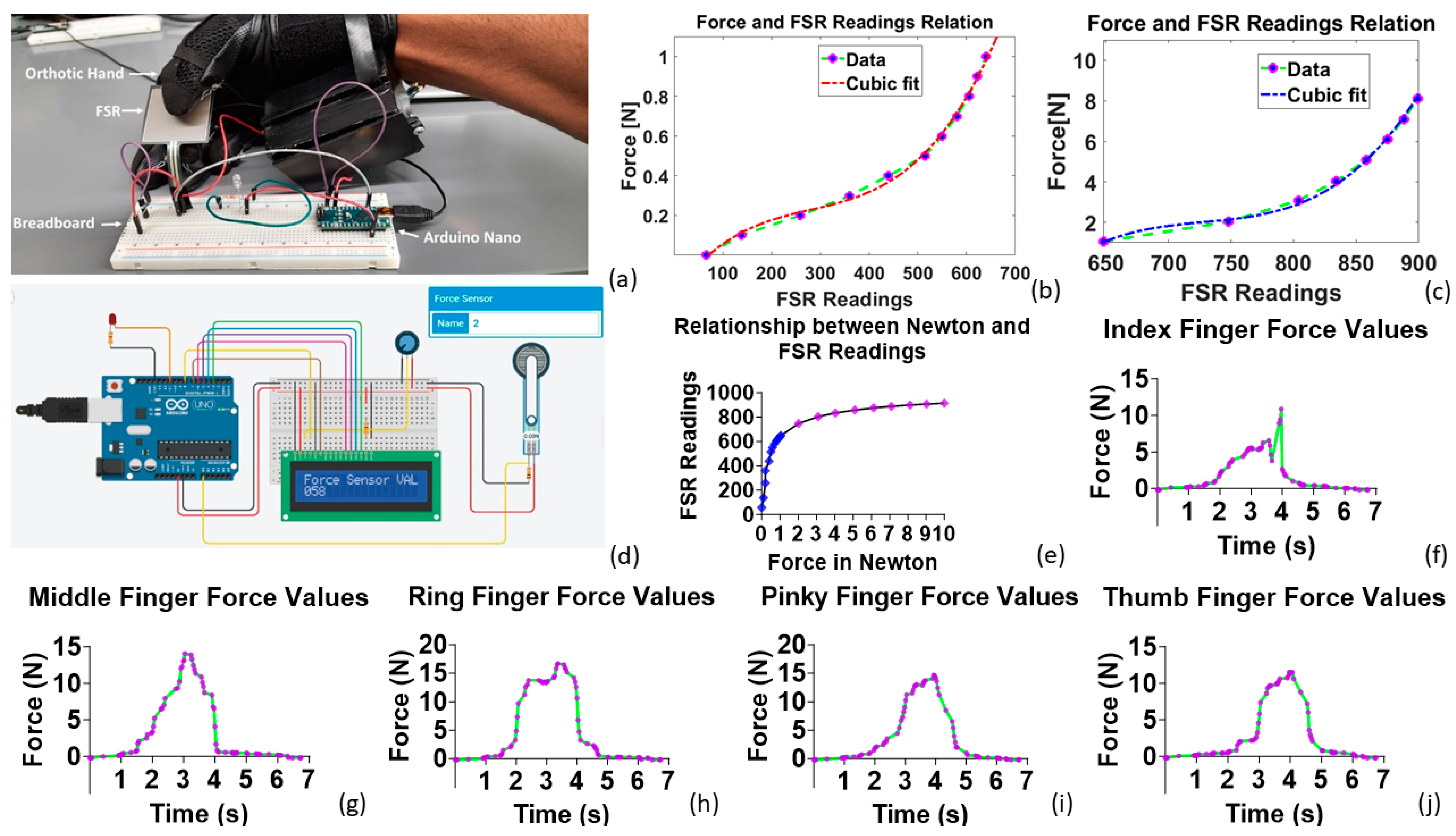
3.5. Force-Sensitive Resistors on NOHAS

Force-sensing resistors (FSRs) were used for testing the force output or, in other terms, the squeezing ability of NOHAS. In essence, FSRs change their resistance in response to external pressure, force, or stress placed on their surfaces. When we apply a notable amount of external force, the conductive film in an FSR is distorted against the substrate. FSRs generally have a vent or a space for forcing the air out. The resistance value was observed to decrease when the conductive ink region contacted the region of the conductive film. We tested different FSRs that could be used in our orthotic hand.
During our experiments, we tested FSRs and found that they have several advantages such as their small size, low cost, and high shock resistance. However, FSRs do have some limitations, such as low precision, and their sensitivity varies depending on the size. While force-sensing capacitors have better sensitivity and long-term stability, their driving circuits are bulky and more complex. We observed that a 1.5-inch FSR had very high sensitivity, with even a small amount of force causing a noticeable change in the FSR readings. On the other hand, A101 FSR and DF9–16 FSR had lower sensitivity, requiring more force to produce noticeable changes. However, for embedding the FSRs onto NOHAS, we determined that the A101 FSR was the best option due to its small size and ease of use. Figure 8a shows the experimental setup of NOHAS when analyzing the properties of the 1.5-inch FSR. The FSR reading corresponds to the voltage output and the mapping is as follows: 0 V corresponds to 0 FSR reading or 0 N force, and 5 V corresponds to 1024 FSR reading or 100 N force [78]. This relationship is dependent on the choice of pulldown resistor and supply voltage. The FSR reading is associated with 10-bit ADC used for reading.
Simulations were conducted to analyze the properties of the FSR, including its resistance and load bearing capacity. Figure 8d shows a simulation method which was carried out using a potentiometer for a three-terminal resistor with a sliding or revolving contact region to change the input force magnitude. We used potentiometers in our circuits to act as variable voltage dividers and to measure voltage accurately. In the simulation, changes in the signal level (FSR reading) were recorded from the LED display. During the simulation, a 10 kΩ resistor was connected to the FSR, which was then connected to the ground. The other end of the FSR was connected to the power supply. The simulation results showed changes in signal levels with variations in the applied force, which provided valuable insights into the properties and behavior of the FSR.
The result for the simulation is shown in Figure 8e. Initially, the FSR reading was 0. But when the force value was increased with an increment of 0.1 up to 1 N, we observed an increase in FSR value from 58 to 650, which is a rapid change in slope. After this, the values gradually increased to about 900 as the force magnitudes increased to 10 N with an increment of 1 N. We consider the two regions in Figure 8e for FSR reading to force in Newton conversion. The two regions are obtained by curve fitting using MATLAB as are shown in Figure 8b,c and the following relation provides the relationship between the FRS digital reading (x) and the Force output, F(x) in Newton.
F x = f 1 x = p 1 x 3 + p 2 x 2 + p 3 x + p 4   , x   60     650   f 2 x = q 1 x 3 + q 2 x 2 + q 3 x + q 4   , x   650     900
where the contestants are given by:
p 1 = 1.1578 × 10 8             p 2 = 9.7359 ×   10 6     p 3 = 0.0033137     p 4 = 0.18968 q 1 = 1.0343 ×   10 6         q 2 = 0.0022575                   q 3 = 1.6483                     q 4 = 400.58
Figure 8f,j shows the force vs. time plots when all five servo motors (namely index, middle, ring, pinky, and thumb) are actuated individually. We can see a gradual increase in the force magnitude when NOHAS is actuated until 3.5 s. With a short gap after 3.5 s, we can see that NOHAS is in the relaxation phase, and we observe a steady decline in the force output. Notable changes in force happen only when an external force acts upon the FSR. The profiles are slightly different from each other, indicating variations in applying force while wearing the device and this is also dependent on the user.
The actuation of NOHAS was performed in a few steps. In the first step, the actuation was carried out by pressing the button in the app. During this time, the FSR values were about 200 (0.18 N force) in the display. In the next step of actuation, there was a higher amount of force acting and the values increased up to around 500 (0.48 N force) and in the next step, even more force was acted upon, and the readings went up to about 800 (2.82 N force). The maximum values in the output were observed at around 940 (13.16 N force). We did not want to actuate the servo motors even more because it may have led to the tangling of tendons on the servo motors and the device might have got damaged. Next, the relaxation phase was performed in steps and we can see that the FSR values displayed in Arduino decreased slowly until they dropped to 0. The same procedure was followed for all the five servo motors, and we found that in all cases, the FSR readings accurately reflected the squeezing ability of NOHAS. The FSR readings were converted to Force readings for easy understanding of squeezing ability. In Figure 8f,j, we may notice a few red connection lines with no green points. This is caused by the delay in the actuation of the servo motors. The main reason for this is the delay caused by ESP 8266 with respect to the hotspot and mobile phone.

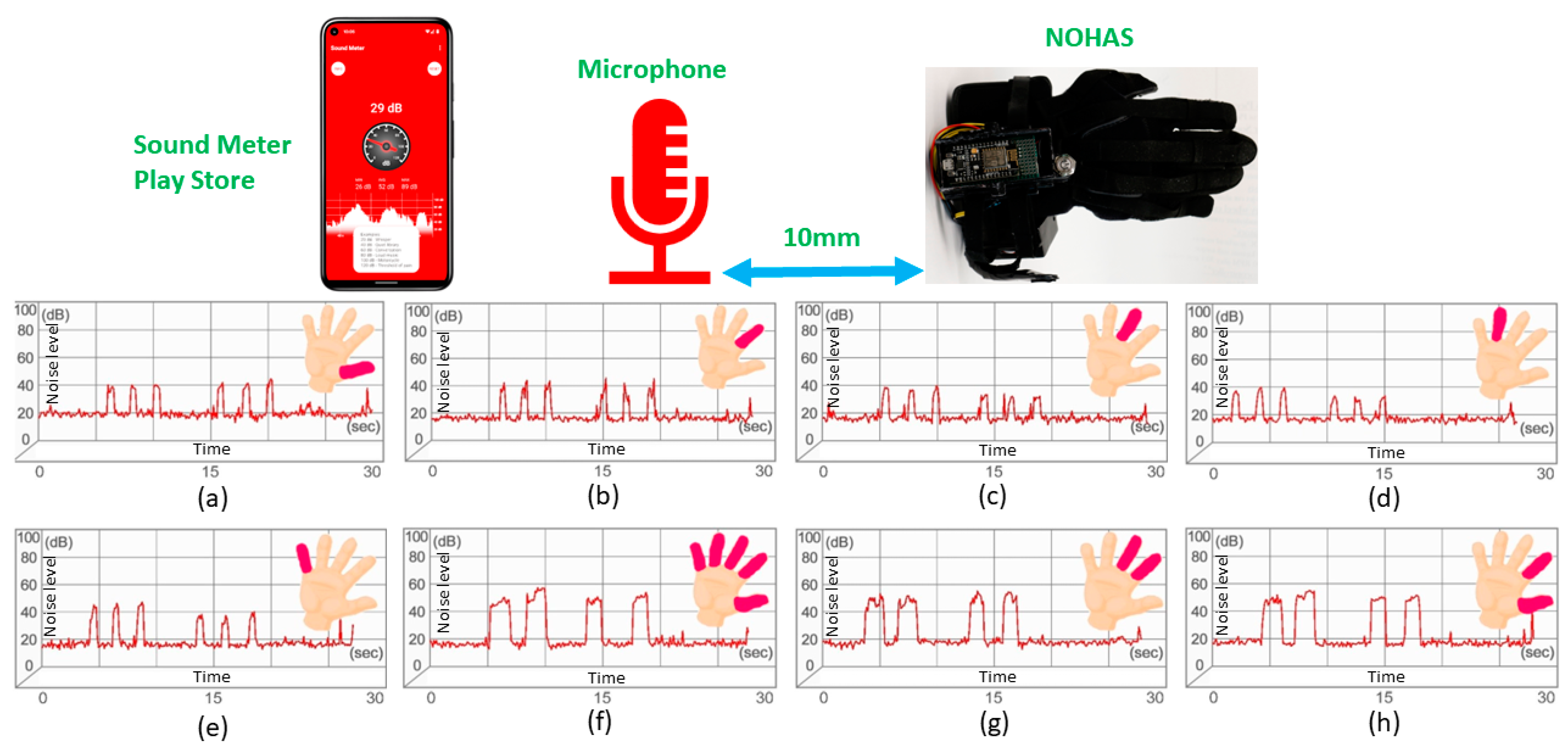
3.6. Servo Noise Measurement Experiment

Servo motors are great for actuation due to their speed and energy efficiency [79,80,81]. However, their drawback is the audible noise that comes out of the motor during actuation. For noise measurement in our robotic hand, we followed a similar procedure to quantify actuator noise to the procedure published using the Qualtrics web platform by researchers in [82]. To record the noise, they connected each servo motor to a power supply. It was controlled using a 490 Hz pulse width modulation signal by Arduino IDE. To reduce resonance when recording, the equipment was turned on and the servo motors were kept on a tiny cloth. Each servo motor performed a 180-degree sweep when unloaded. It was coded in such a way that a similar back and forth movement of 2 s in each direction was made in continuous rotation. This made sure the sounds were comparable, even though the lengths of the clips varied from 0.5 s to 5 s due to speed differences. They used a Zoom H2N microphone for recording in a studio. After all noises were captured, each clip’s volume was normalized, and it was cropped to distinguish the noise during the 0–180–0-degree change. In our case, we used a mobile phone to record servo motor noise.
Servo motors follow the same principles as standard AC and DC motors, except for the positioning device to which they are coupled. This makes closed-loop system control possible. Understanding and rectifying some of the most common problems that could occur is essential for successfully managing a servo motor system; in our case, where the servo motors are used for active finger actuation. Noise during actuation will heat up the servo motor. A motor that is heating up while running can cause problems that might eventually lead the motor or other machine parts to fail.

3.7. Understanding Servo Motor Audio Noise and Overheating

We suspected that the sharp noise could cause some level of discomfort to the people who are wearing it. If they wear this device for a long time and hear this noise continuously, they might feel they need to remove the glove. So, we want to quantify the level of noise. The audio noise of RC servo motors is caused by the vibration of components such as gears. This audio noise should be quantified as it may cause inconvenience to users. The magnitude of this noise could vary depending on other factors such as the surface quality of the gears. The servo motor noise problem could be either intermittent or constant, with the motor stopping and making a chattering noise. While the output shaft of the motor is stationary, it occasionally oscillates to some extent. The chattering noise observed is generally due to positioning blunders, with a drive module setup issue or loss of settings-related causes. Although servo motor bearings were usually sealed, moisture could still enter and cause the lubricant to dry out. The servo motor required a service that included a bearing swap when typical troubleshooting, such as checking settings and parameters. This issue needed to be resolved since it worsened over time and eventually led to the failing of the motors. For each of the five fingers individually, noise intensity was measured. The five servo motors’ noise levels were tested using the free Sound Meter app from the Google Play store. The setup for this experiment comprised placing the microphone near the servo motors and actuating the fingers, as shown in Figure 9. The same experiment was conducted multiple times to verify the accuracy of the noise levels. But the noise levels of all the five servo motors are different from each other, which could be due to the loading conditions while pulling the tendons. Figure 9 shows the individual and combined noise levels for each servo motor.
The noise level produced by the servo motors when they are operated fully, partly, or simultaneously was analyzed. The thumb finger servo motor’s noise level is represented by Figure 9a. Here, the initial three peaks reflect the three successive steps of actuation, and the last three peaks represent the three successive steps of relaxation. The noise level of the servo motors of each finger is characterized one by one. The index finger, middle finger, ring finger, and pinky finger servos are designated as (a) to (e), respectively. (f) denotes the magnitude level and the width of the audio noise of all five servo motors operating simultaneously from all five fingers. This symbolizes the closing of the entire fist. The first two peaks denote the actuation phase. The relaxation phase from the fist close to its initial rest position is represented by the next two peaks of (f). (g) stands for the peace sign, in which the middle and index fingers are stretched, and the thumb is folded. This stage often involves the activation of two fingers. The pinch gesture is shown in Figure 9h, where just two fingers, namely the thumb and index finger, are actuated, leaving the other fingers in the resting position. The first two peaks show the actuation phase, while the last two peaks show NOHAS returning to the resting phase. The average noise level is around 40 dB. A noise level of up to 60 dB was observed when all the five servo motors were actuated at once in the first gesture. People might feel comfort or discomfort from the audible noise of NOHAS which cannot be solely determined based on peak noise levels alone. Factors such as frequency, duration, and temporal patterns of noise also significantly influence individuals’ perception of the sound. Furthermore, even at low levels where direct damage to the hearing organ does not occur, noise can still induce stress to individuals.
According to the Centers for Disease Control and Prevention (CDC) [38], a soft whisper level of sound measures at approximately 30 dB. Normal conversation and air conditioner sounds measure at approximately 60 dB. These respective sounds were found safe and typically not causing any damage to the hearing organ. But the noise arising from a washing machine/dishwasher (70 dB) and city traffic (80–85 dB) were found to be annoying. Motorcycles (95 dB) and gas-powered machines (80–85 dB) were found to cause damage to hearing organs if there was continuous exposure to these environments. Therefore, we assessed the performance of the servo motors used in the hand orthosis from this standard and considered the comfort of the users [83,84].
Regarding the reliability of smartphone apps for noise measurement, some studies have been carried out. The findings in [85,86] indicate that the iOS platform’s SLA Lite emerged as the best app, while the second-best app, namely Sound Meter, was associated with the Android platform, which we used to quantify the noise from NOHAS. On the Android platform, Sound Meter was identified as the most accurate app, exhibiting a slight undermeasurement of noise by 1.93 dB(A)—within the generally acceptable error threshold of ±2 dB(A). However, analysis across all reference levels revealed an average differential from the actual noise level ranging between 3 and 4 dB(A). It can be asserted that with a considerable number of sample measurements, Android apps like Sound Meter and Decibel Pro are likely to converge on a noise measurement level that is approximately within ±2 dB(A) of the true noise levels. The dB(A) measurements were compared to true noise levels obtained through a calibrated sound level meter. The investigation in [87] revealed that app-based measurements effectively captured average noise levels, exhibiting a variance of ±2 dB when compared to measurements obtained using the gold standard sound level meter. dB(A) represents the weighted average of the sound pressure in dB, which is tailored to match the human ear’s frequency response.

4. Human Subject Testing (Study 2)

To enhance the gripping of objects and to prevent slipping while grasping fragile items, NOHAS’s fingers were sealed with rubberized tips, as shown in Figure 10a,b. This enabled the human subjects to grasp items effectively.

4.1. Objective of Human Subject Testing

Human subject testing was conducted to collect feedback about the device’s functionality and effectiveness in grasping objects because human subjects will not be able to voluntarily control their grasping. Hence, before wearing the glove, we instructed the human subjects not to control or move their wrist voluntarily. They can only control their wrist using the app in the mobile phone. The human subjects were allowed to use the mobile phone by themselves with their other hand.

4.2. Eligibility

Healthy participants who did not have pre-existing health conditions, exhibit symptoms of fever or cold, have physical limitations, fractures, or allergies to wool or cotton were suitable for human subject testing. We set these as guidelines in our IRB application. Our study was approved by UT Dallas IRB.

4.3. Participant Inclusion and Exclusion Criteria

We selected participants from members of the HBS lab at UT Dallas. The HBS lab is dedicated to the study of fundamental and applied science of humanoid robots, biorobotics, smart materials, and structures. This group was well-suited for testing NOHAS as they can use their own research experiences to provide valuable insights into the design of the orthotic hand. We believed that testing the device with this group would yield accurate feedback. For instance, if the device is perceived as heavy or flexible, they can articulate these observations properly. A student researching soft robots might even propose innovative ideas, such as replacing noise-generating servos with other types of actuators. This was chosen to receive comprehensive and constructive comments from this group.

4.4. Recruitment Method

The principal investigator for this study sent out emails to the HBS lab mailing list after the approval of the director of HBS lab. Involvement was based on the response of the person to the mail request, after reviewing the consent form and the study plan. A written consent form signed by the participant was required before the start of the experiment. We did not record the age or name of the participants. The human subject test was conducted for a total of ten subjects aged between 20 and 45, consisting of eight males and two females following the approved IRB protocol (IRB-23-31).

4.5. Collection of Data

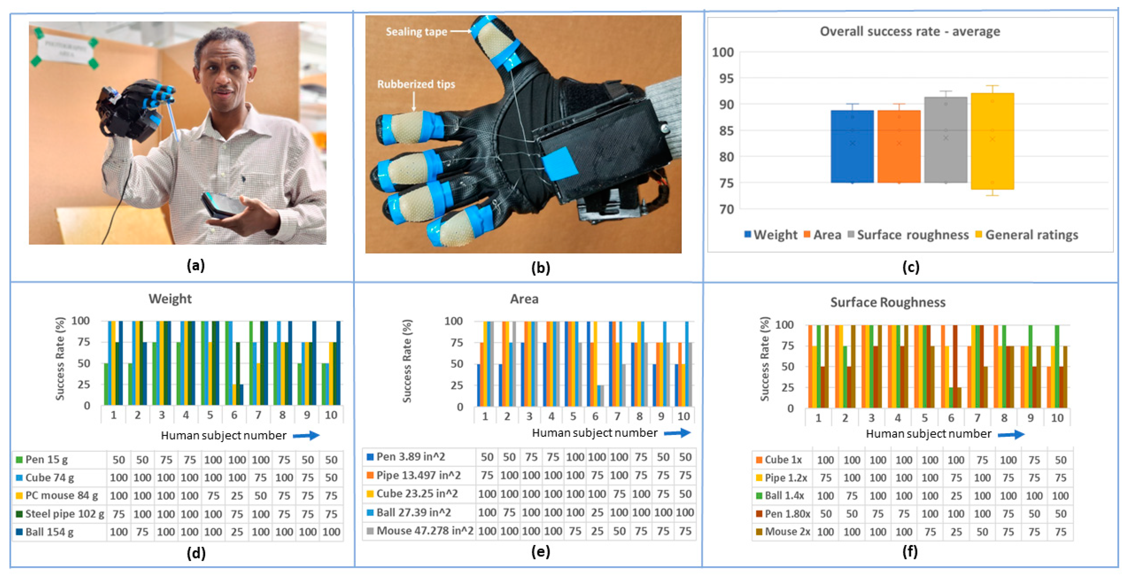
  • Participants were asked to come to the HBS lab during their free time and the experimental procedure was explained to them during the first 10 min. The ARAT kit was opened, and the experimenter explained the mobile app layout to the participants. They were allowed to use the mobile app independently and operate the glove. We selected the ARAT kit as it is a frequently used tool in stroke rehabilitation and standard assessment for hand function;
  • Next, participants were instructed to wear NOHAS and pick up standard objects from the ARAT kit, which included a ball, boxes of various sizes, plastic hard cups, metal tubes, etc. The entire activity was captured on video, focusing solely on the participants’ hand movements and grasping actions, with their faces excluded from the recording. Throughout the process, participants used a mobile application to control the glove;
  • Afterwards, participants were asked to remove the glove and safely place it in the provided location. Participants were not asked any demographic questions. Instead, they were requested to provide a rating as per the consent form, assessing the orthotic hand’s performance on a scale of 4 to 1, where 4 denoted excellent, 3 very good, 2 good, and 1 poor. The entire process took around 15 min;
  • Finally, participants were thanked for their time, and they left the lab. The video of this data collection is shown in the overview of NOHAS available on the HBS lab website at the following link: https://youtu.be/RtTiUP9PP94 (accessed on 6 December 2023).
The human subject test results and analyses were categorized based on three parameters, including object weight, area, and surface roughness, as shown in Figure 10c. We obtained feedback from the human subjects that these parameters directly affected the grasping task of different objects using NOHAS. People were able to give different ideas about NOHAS and its efficiency in grasping objects such as a pen, ball, box, PC mouse, and steel pipe. These objects were used in the test because they resembled most of the objects which we use in our day-to-day life. We were able to find out that the human subjects were able to grasp the ball very easily because when the glove closes, the ball was firmly placed next to the main servo motor housing case. Even though the ball had a smooth and shiny surface, the glove was able to provide an excellent grip. The motor case provided additional support for the ball. From this, we can understand that smooth objects can easily be grasped by NOHAS. While lifting boxes, the servo motor casing was able to provide excellent support because of the well-defined edges and smooth surface. For the pen, the rating was low because lifting it from the table in a flat position was difficult. This was because of the small diameter of the pen. If the pen was picked up from a pen stand in a vertical orientation, it would have been much easier to grasp, and the rating would have been much higher. We were also able to grasp the pen from a pen stand. Some subjects felt difficulty in lifting and moving the personal computer (PC) mouse because of its shape and slippery surface. The steel pipe received good ratings because of its perfect size, shiny surface, and easily graspable structure.
Figure 10d describes the grasping success rate for different objects when weight is considered. The objects are arranged in ascending order from lowest weight to heaviest. It was found that the average weight percentage ratings for the pen, cube, PC mouse, steel pipe, and ball were 72.5, 90, 77.5, 87.5, and 75, respectively, as per Figure 10d. From this, we can infer that considering the weight of objects, NOHAS was able to grasp the cube easier. The average area ratings for the pen, pipe, cube, ball, and mouse are 72.5, 87.5, 90, 90, and 77.5, respectively, as per Figure 10e. The human subjects felt it was easier to grasp the cube and ball. The average surface roughness ratings for the cube, pipe, ball, pen, and mouse are 90, 87.5, 90, 72.5, and 77.5, respectively, as per Figure 10f. Figure 10c shows a box and whisker plot for the human subject test. The yellow bar is the overall general feedback rating given by the human subjects. The median, lower quartile (Q1), upper quartile (Q3), lower extreme, and upper extreme values for the weight category are 75, 75, 87.5, 75, and 90 respectively. Similarly, for area category, these values are 75, 75, 87.5, 75, and 90. Regarding surface roughness, the values are 75, 75, 92.5, 75, and 92.5, respectively. Considering general feedback, the median, lower quartile (Q1), upper quartile (Q3), lower extreme, and upper extreme values are 80, 75, 90.5, 72.5, and 93.5 respectively. Our future work will focus on grasping tests with stroke subjects, considering patient outcomes and psychology.
Several recent studies [88,89,90,91] highlight the critical need to tailor rehabilitation treatments to patients’ psychophysiological states, emphasizing personalized approaches in robotic-assisted therapies. The integration of advanced technologies, like hand exoskeletons and psychophysiological-aware control strategies, demonstrates a commitment to addressing the unique conditions of individual patients. These robotic systems aim to optimize therapy outcomes by sensing and adapting to psychophysiological states, ensuring accurate and efficient motor interventions while enhancing patient comfort and minimizing fatigue. The emphasis on active-assisted training, virtual reality games, and the integration of linguistic interaction further highlights a holistic approach to rehabilitation, acknowledging the multifaceted nature of patient well-being. These advancements collectively signify a paradigm shift towards tailoring the behavior of robotic systems to the individual complexities of patients, ultimately maximizing the effectiveness and impact of motor rehabilitation therapies. This personalized approach is particularly pertinent to devices like NOHAS, where understanding and adapting to the intricate conditions of everyone becomes paramount. NOHAS was developed using parametric CAD software, which can be easily modified to fit in varied sizes. There are some commercially available exoskeletons like Gloreha [58,92], which have good functionalities, especially for inpatient rehabilitation training. Despite its advantages, its bulkiness due to the accessories and noise from its pneumatic actuators may pose challenges in certain settings.

5. Conclusions

We have presented an app-controlled novel hand orthosis actuated by servo motors (NOHAS) which is cost effective, energy-efficient, easily worn, and has potential for use in activities of daily living and as an assistive device for persons with impaired hand function. Orthotic hands with servo motors play a pivotal role in stroke rehabilitation by facilitating motor recovery through a mechanism known as task-oriented repetitive training. These devices, often controlled by smartphone commands, enable post-stroke subjects to engage in purposeful and repetitive hand movements. The precision and adjustability of servo motor-driven orthotic hands allow for tailored rehabilitation exercises, targeting specific muscle groups and joint ranges affected by stroke-induced impairments. Repetitive movements aid in neuroplasticity, promoting the rewiring of neural pathways in the brain to enhance motor control and coordination. The smartphone-controlled interface provides a user-friendly and adaptable platform, allowing rehabilitation professionals to customize exercises based on individual patient needs and progress. This technology thus offers an innovative and effective means to augment traditional rehabilitation approaches, promoting functional recovery and enhancing the quality of life for post-stroke subjects, specifically for ischemic stroke. The characterization of the angle (i.e., the flexion of the PIP, DIP, and MCP joint with respect to time), cyclic actuation, and grasping capabilities were performed to quantify the properties of NOHAS. The amount of force NOHAS can apply or fasten is also a very important characteristic feature, which gives us a very good idea of NOHAS’s ability to hold and carry heavy objects. The quantification of auditory noise indicated that the inexpensive servo motors do not generate audio noise significant enough to cause problems. This information provides us with a better understanding of noise levels while wearing NOHAS and helps assess the seamless functioning of the servo motors. We conducted a human subject test for NOHAS after IRB approval and it was found out that ten subjects successfully grasped few objects and were not able to do the same for other objects from a standard ARAT kit. The ideas we obtained after the human subject test will be used for the improvement of the device in terms of design and manufacturing. The device presented is a proof of concept and it needs further testing in practical scenarios in healthy subjects and post-stroke subjects. We will be able to improve the functioning of NOHAS by redesigning it further, considering design, manufacturing, and control aspects. One aspect is replacing our current servo motors with small and smoother ones which create less noise and are more efficient. This will be our future work. This may add cost, but optimization is needed to address all the issues.

Supplementary Materials

A video that shows the design, structure, properties, and function of our device is provided. It is also available on our YouTube Channel (HBS lab) https://youtu.be/RtTiUP9PP94 (accessed on 6 December 2023).

Author Contributions

Conceptualization, Y.T.; Methodology, E.R.S.M. and N.I.; Software, E.R.S.M. and A.G.; Formal analysis, E.R.S.M. and Y.T.; Investigation, E.R.S.M. and N.I.; Resources, Y.T.; Writing—original draft, E.R.S.M.; Writing—review & editing, A.G., N.I. and Y.T.; Project administration, Y.T.; Funding acquisition, Y.T. All authors have read and agreed to the published version of the manuscript.

Funding

The research was partially supported by Internal fund from Research Enhancement.

Data Availability Statement

Data are contained within the article.

Acknowledgments

We would like to thank our senior design team at UT Dallas for their initial contributions to this project. We would like to extend our special thanks to Taylor Hollers, Joe Torres, Roy Lara, Anothony Dyoub, Dominic Labarge, and Jin Sik Woo. Special thanks to Jin Sik Woo for the Blynk App. We also would like to thank Robert Hart and Todd Polk.

Conflicts of Interest

The authors declare no conflict of interest.

References

  1. Donkor, E.S. Stroke in the century: A snapshot of the burden, epidemiology, and quality of life. Stroke Res. Treat. 2018, 2018, 3238165. [Google Scholar]
  2. Toth, L.; Schiffer, A.; Nyitrai, M.; Pentek, A.; Told, R.; Maroti, P. Developing an anti-spastic orthosis for daily home-use of stroke patients using smart memory alloys and 3D printing technologies. Mater. Des. 2020, 195, 109029. [Google Scholar] [CrossRef]
  3. Yurkewich, A.; Hebert, D.; Wang, R.H.; Mihailidis, A. Hand extension robot orthosis (HERO) glove: Development and testing with stroke survivors with severe hand impairment. IEEE Trans. Neural Syst. Rehabil. Eng. 2019, 27, 916–926. [Google Scholar] [CrossRef] [PubMed]
  4. Park, C.B.; Park, H.-S. PorTable 3D-printed hand orthosis with spatial stiffness distribution personalized for assisting grasping in daily living. Front. Bioeng. Biotechnol. 2023, 11, 895745. [Google Scholar] [CrossRef] [PubMed]
  5. Kaskutas, V.; Powell, R. The impact of flexor tendon rehabilitation restrictions on individuals’ independence with daily activities: Implications for hand therapists. J. Hand Ther. 2013, 26, 22–29. [Google Scholar] [CrossRef] [PubMed]
  6. Dindorf, R.; Wos, P. Using the bioelectric signals to control of wearable orthosis of the elbow joint with bi-muscular pneumatic servo-drive. Robotica 2020, 38, 804–818. [Google Scholar] [CrossRef]
  7. Cartagena, P.D.; Naranjo, J.E.; Saltos, L.F.; Garcia, C.A.; Garcia, M.V. Multifunctional exoskeletal orthosis for hand rehabilitation based on virtual reality. In Information and Communication Technologies of Ecuador (TIC. EC); Springer: Berlin/Heidelberg, Germany, 2018; pp. 209–221. [Google Scholar]
  8. Megalingam, R.K.; Manoharan, S.K.; Mohandas, S.M.; Reddy, C.P.K.; Vijay, E.; Naveen, P.N.V.K.; Chandrika, D. Wearable Hand Orthotic Device for Rehabilitation: Hand Therapy with Multi-Mode Control and Real-Time Feedback. Appl. Sci. 2023, 13, 3976. [Google Scholar] [CrossRef]
  9. Veale, A.J.; Xie, S.Q. Towards compliant and wearable robotic orthoses: A review of current and emerging actuator technologies. Med. Eng. Phys. 2016, 38, 317–325. [Google Scholar] [CrossRef]
  10. Gretsch, K.F.; Lather, H.D.; Peddada, K.V.; Deeken, C.R.; Wall, L.B.; Goldfarb, C.A. Development of novel 3D-printed robotic prosthetic for transradial amputees. Prosthet. Orthot. Int. 2016, 40, 400–403. [Google Scholar] [CrossRef]
  11. Dereshgi, H.A.; Hüseyin, D.; Demir, D.; Türe, N.F. Orthoses: A Systematic Review. J. Smart Syst. Res. 2021, 2, 135–149. [Google Scholar]
  12. Cheng, N.; Phua, K.S.; Lai, H.S.; Tam, P.K.; Tang, K.Y.; Cheng, K.K.; Yeow, R.C.-H.; Ang, K.K.; Guan, C.; Lim, J.H. Brain-computer interface-based soft robotic glove rehabilitation for stroke. IEEE Trans. Biomed. Eng. 2020, 67, 3339–3351. [Google Scholar] [CrossRef]
  13. Cantillo-Negrete, J.; Carino-Escobar, R.I.; Carrillo-Mora, P.; Rodriguez-Barragan, M.A.; Hernandez-Arenas, C.; Quinzaños-Fresnedo, J.; Hernandez-Sanchez, I.R.; Galicia-Alvarado, M.A.; Miguel-Puga, A.; Arias-Carrion, O. Brain-computer interface coupled to a robotic hand orthosis for stroke patients’ neurorehabilitation: A crossover feasibility study. Front. Hum. Neurosci. 2021, 15, 656975. [Google Scholar] [CrossRef]
  14. Chowdhury, A.; Raza, H.; Meena, Y.K.; Dutta, A.; Prasad, G. An EEG-EMG correlation-based brain-computer interface for hand orthosis supported neuro-rehabilitation. J. Neurosci. Methods 2019, 312, 1–11. [Google Scholar] [CrossRef]
  15. Cantillo-Negrete, J.; Carino-Escobar, R.I.; Carrillo-Mora, P.; Elias-Vinas, D.; Gutierrez-Martinez, J. Motor imagery-based brain-computer interface coupled to a robotic hand orthosis aimed for neurorehabilitation of stroke patients. J. Healthc. Eng. 2018, 2018, 1624637. [Google Scholar] [CrossRef] [PubMed]
  16. Pichiorri, F.; Morone, G.; Petti, M.; Toppi, J.; Pisotta, I.; Molinari, M.; Paolucci, S.; Inghilleri, M.; Astolfi, L.; Cincotti, F.; et al. Brain–computer interface boosts motor imagery practice during stroke recovery. Ann. Neurol. 2015, 77, 851–865. [Google Scholar] [CrossRef] [PubMed]
  17. King, C.E.; Dave, K.R.; Wang, P.T.; Mizuta, M.; Reinkensmeyer, D.J.; Do, A.H.; Moromugi, S.; Nenadic, Z. Performance assessment of a brain–computer interface driven hand orthosis. Ann. Biomed. Eng. 2014, 42, 2095–2105. [Google Scholar] [CrossRef] [PubMed]
  18. Delijorge, J.; Mendoza-Montoya, O.; Gordillo, J.L.; Caraza, R.; Martinez, H.R.; Antelis, J.M. Evaluation of a p300-based brain-machine interface for a robotic hand-orthosis control. Front. Neurosci. 2020, 14, 589659. [Google Scholar] [CrossRef] [PubMed]
  19. Lee, J.; Mukae, N.; Arata, J.; Iihara, K.; Hashizume, M. Comparison of feature vector compositions to enhance the performance of NIRS-BCI-triggered robotic hand orthosis for post-stroke motor recovery. Appl. Sci. 2019, 9, 3845. [Google Scholar] [CrossRef]
  20. Dunaway, S.; Dezsi, D.B.; Perkins, J.; Tran, D.; Naft, J. Case report on the use of a custom myoelectric elbow–wrist–hand orthosis for the remediation of upper extremity paresis and loss of function in chronic stroke. Mil. Med. 2017, 182, e1963–e1968. [Google Scholar] [CrossRef] [PubMed]
  21. Nizamis, K.; Rijken, N.H.; Van Middelaar, R.; Neto, J.; Koopman, B.F.; Sartori, M. Characterization of forearm muscle activation in duchenne muscular dystrophy via high-density electromyography: A case study on the implications for myoelectric control. Front. Neurol. 2020, 11, 231. [Google Scholar] [CrossRef]
  22. Yoo, H.-J.; Lee, S.; Kim, J.; Park, C.; Lee, B. Development of 3D-printed myoelectric hand orthosis for patients with spinal cord injury. J. Neuroeng. Rehabil. 2019, 16, 162. [Google Scholar] [CrossRef]
  23. Peters, H.T.; Page, S.J.; Persch, A. Giving them a hand: Wearing a myoelectric elbow-wrist-hand orthosis reduces upper extremity impairment in chronic stroke. Arch. Phys. Med. Rehabil. 2017, 98, 1821–1827. [Google Scholar] [CrossRef] [PubMed]
  24. Martins, H.V.; Setti, J.; Guimarães, C. Handy Orthotics: Considerations on User-Centered Methodology During Development Stages of Myoelectric Hand Orthosis for Daily Assistance. In XXVII Brazilian Congress on Biomedical Engineering, Proceedings of CBEB 2020, Vitória, Brazil, 26–30 October 2020; Springer: Berlin/Heidelberg, Germany, 2022; pp. 1277–1283. [Google Scholar]
  25. Pahk, H.J.; Lee, D.S.; Park, J.H. Ultra precision positioning system for servo motor–piezo actuator using the dual servo loop and digital filter implementation. Int. J. Mach. Tools Manuf. 2001, 41, 51–63. [Google Scholar] [CrossRef]
  26. Sevinc, A. A full adaptive observer for DC servo motors. Turk. J. Electr. Eng. Comput. Sci. 2003, 11, 117–130. [Google Scholar]
  27. Vukosavic, S.N.; Stojic, M.R. Suppression of torsional oscillations in a high-performance speed servo drive. IEEE Trans. Ind. Electron. 1998, 45, 108–117. [Google Scholar] [CrossRef]
  28. Chung, K.C.W. Servo speed control of traveling-wave ultrasonic motors using pulse width modulation. Electr. Power Compon. Syst. 2001, 29, 707–722. [Google Scholar]
  29. Feng, G.-H.; Pan, Y.-L. Establishing a cost-effective sensing system and signal processing method to diagnose preload levels of ball screws. Mech. Syst. Signal Process. 2012, 28, 78–88. [Google Scholar] [CrossRef]
  30. Ramírez, A.; Garrido, R.; Mondié, S. Velocity control of servo systems using an integral retarded algorithm. ISA Trans. 2015, 58, 357–366. [Google Scholar] [CrossRef] [PubMed]
  31. Jung, D.; Levy, E.J.; Zhou, D.; Fink, R.; Moshe, J.; Earl, A.; Tsiotras, P. Design and development of a low-cost test-bed for undergraduate education in UAVs. In Proceedings of the 44th IEEE Conference on Decision and Control, Seville, Spain, 15 December 2005; IEEE: Piscataway, NJ, USA, 2005; pp. 2739–2744. [Google Scholar]
  32. Dutta, D.; Aruchamy, S.; Mandal, S.; Sen, S. Poststroke grasp ability assessment using an intelligent data glove based on action research arm test: Development, algorithms, and experiments. IEEE Trans. Biomed. Eng. 2021, 69, 945–954. [Google Scholar] [CrossRef]
  33. Kim, D.H.; Lee, Y.; Park, H.-S. Cooperative Hand Therapy via a Soft, Wearable, and Unilateral Telerobotic System. IEEE Trans. Biomed. Eng. 2022, 70, 366–377. [Google Scholar] [CrossRef]
  34. Coyle, S.; Majidi, C.; LeDuc, P.; Hsia, K.J. Bio-inspired soft robotics: Material selection, actuation, and design. Extrem. Mech. Lett. 2018, 22, 51–59. [Google Scholar] [CrossRef]
  35. Zhao, H.; Jalving, J.; Huang, R.; Knepper, R.; Ruina, A.; Shepherd, R. A helping hand: Soft orthosis with integrated optical strain sensors and EMG control. IEEE Robot. Autom. Mag. 2016, 23, 55–64. [Google Scholar] [CrossRef]
  36. Byl, N.N.; Abrams, G.M.; Pitsch, E.; Fedulow, I.; Kim, H.; Simkins, M.; Nagarajan, S.; Rosen, J. Chronic stroke survivors achieve comparable outcomes following virtual task specific repetitive training guided by a wearable robotic orthosis (UL-EXO7) and actual task specific repetitive training guided by a physical therapist. J. Hand Ther. 2013, 26, 343–352. [Google Scholar] [CrossRef] [PubMed]
  37. Woo, Y.; Jeon, H.; Hwang, S.; Choi, B.; Lee, J. Kinematics variations after spring-assisted orthosis training in persons with stroke. Prosthet. Orthot. Int. 2013, 37, 311–316. [Google Scholar] [CrossRef] [PubMed]
  38. Chen, Y.; Abel, K.T.; Janecek, J.T.; Chen, Y.; Zheng, K.; Cramer, S.C. Home-based technologies for stroke rehabilitation: A systematic review. Int. J. Med. Inform. 2019, 123, 11–22. [Google Scholar] [CrossRef] [PubMed]
  39. Hameed, H.K.; Hassan, W.Z.W.; Shafie, S.; Ahmad, S.A.; Jaafar, H. A review on surface electromyography-controlled hand robotic devices used for rehabilitation and assistance in activities of daily living. JPO J. Prosthet. Orthot. 2020, 32, 3–13. [Google Scholar] [CrossRef]
  40. Gaiser, I.N.; Pylatiuk, C.; Schulz, S.; Kargov, A.; Oberle, R.; Werner, T. The FLUIDHAND III: A multifunctional prosthetic hand. JPO J. Prosthet. Orthot. 2009, 21, 91–96. [Google Scholar] [CrossRef]
  41. Zuniga, J.M.; Peck, J.; Srivastava, R.; Katsavelis, D.; Carson, A. An open source 3D-printed transitional hand prosthesis for children. JPO J. Prosthet. Orthot. 2016, 28, 103–108. [Google Scholar] [CrossRef]
  42. Ramaji, R.Y.; Daryabor, A.; Bani, M.A. The effect of ulnar deviation orthosis in patients with zigzag deformity due to rheumatoid hand. JPO J. Prosthet. Orthot. 2021, 33, 203–207. [Google Scholar] [CrossRef]
  43. Plessis, T.D.; Djouani, K.; Oosthuizen, C. A review of active hand exoskeletons for rehabilitation and assistance. Robotics 2021, 10, 40. [Google Scholar] [CrossRef]
  44. Qassim, H.M.; Hasan, W.W. A review on upper limb rehabilitation robots. Appl. Sci. 2020, 10, 6976. [Google Scholar] [CrossRef]
  45. Deng, E.; Tadesse, Y. A soft 3D-printed robotic hand actuated by coiled SMA. Actuators 2020, 10, 6. [Google Scholar] [CrossRef]
  46. Neto, A.R.; Fajardo, J.; da Silva, W.H.A.; Gomes, M.K.; de Castro, M.C.F.; Fujiwara, E.; Rohmer, E. Design of tendon-actuated robotic glove integrated with optical fiber force myography sensor. Automation 2021, 2, 187–201. [Google Scholar] [CrossRef]
  47. Singh, A.P.; Palani, D.; Ahmed, O.; Matharu, P.S.; Linn, T.; Nguyen, T.; Tadesse, Y. HBS-1.2: Lightweight Socially Assistive Robot with 6-Ply Twisted Coiled Polymer Muscle-Actuated Hand. Actuators 2023, 12, 312. [Google Scholar] [CrossRef]
  48. Oña, E.D.; Garcia-Haro, J.M.; Jardón, A.; Balaguer, C. Robotics in health care: Perspectives of robot-aided interventions in clinical practice for rehabilitation of upper limbs. Appl. Sci. 2019, 9, 2586. [Google Scholar] [CrossRef]
  49. Lin, F.; Ajay, J.; Langan, J.; Cavuoto, L.; Nwogu, I.; Subryan, H.; Xu, W. QM-FOrMS: A portable and cost-effective upper extremity rehabilitation system. Smart Health 2019, 14, 100080. [Google Scholar] [CrossRef]
  50. Bobin, M.; Bimbard, F.; Boukallel, M.; Anastassova, M.; Ammi, M. SpECTRUM: Smart ECosystem for sTRoke patient’s Upper limbs Monitoring. Smart Health 2019, 13, 100066. [Google Scholar] [CrossRef]
  51. Park, Y.; Jo, I.; Lee, J.; Bae, J. A dual-cable hand exoskeleton system for virtual reality. Mechatronics 2018, 49, 177–186. [Google Scholar] [CrossRef]
  52. Marconi, D.; Baldoni, A.; McKinney, Z.; Cempini, M.; Crea, S.; Vitiello, N. A novel hand exoskeleton with series elastic actuation for modulated torque transfer. Mechatronics 2019, 61, 69–82. [Google Scholar] [CrossRef]
  53. Conti, R.; Meli, E.; Ridolfi, A. A novel kinematic architecture for portable hand exoskeletons. Mechatronics 2016, 35, 192–207. [Google Scholar] [CrossRef]
  54. Jo, I.; Bae, J. Design and control of a wearable and force-controllable hand exoskeleton system. Mechatronics 2017, 41, 90–101. [Google Scholar] [CrossRef]
  55. Xiao, F.; Gu, L.; Ma, W.; Zhu, Y.; Zhang, Z.; Wang, Y. Real time motion intention recognition method with limited number of surface electromyography sensors for A 7-DOF hand/wrist rehabilitation exoskeleton. Mechatronics 2021, 79, 102642. [Google Scholar] [CrossRef]
  56. Achilli, G.M.; Amici, C.; Dragusanu, M.; Gobbo, M.; Logozzo, S.; Malvezzi, M.; Tiboni, M.; Valigi, M.C. Soft, Rigid, and Hybrid Robotic Exoskeletons for Hand Rehabilitation: Roadmap with Impairment-Oriented Rationale for Devices Design and Selection. Appl. Sci. 2023, 13, 11287. [Google Scholar] [CrossRef]
  57. Nilsen, T.; Hermann, M.; Eriksen, C.S.; Dagfinrud, H.; Mowinckel, P.; Kjeken, I. Grip force and pinch grip in an adult population: Reference values and factors associated with grip force. Scand. J. Occup. Ther. 2012, 19, 288–296. [Google Scholar] [CrossRef] [PubMed]
  58. Kabir, R.; Sunny, M.S.H.; Ahmed, H.U.; Rahman, M.H. Hand rehabilitation devices: A comprehensive systematic review. Micromachines 2022, 13, 1033. [Google Scholar] [CrossRef] [PubMed]
  59. Saharan, L.; Wu, L.; Tadesse, Y. Modeling and simulation of robotic finger powered by nylon artificial muscles. J. Mech. Robot. 2020, 12, 14501. [Google Scholar] [CrossRef]
  60. Ochoa, J.M.; Kamper, D.G.; Listenberger, M.; Lee, S.W. Use of an electromyographically driven hand orthosis for training after stroke. In Proceedings of the 2011 IEEE International Conference on Rehabilitation Robotics, Zurich, Switzerland, 29 June–1 July 2011; IEEE: Piscataway, NJ, USA, 2011; pp. 1–5. [Google Scholar]
  61. Chen, A.; Winterbottom, L.; Park, S.; Xu, J.; Nilsen, D.M.; Stein, J.; Ciocarlie, M. Thumb Stabilization and Assistance in a Robotic Hand Orthosis for Post-Stroke Hemiparesis. IEEE Robot. Autom. Lett. 2022, 7, 8276–8282. [Google Scholar] [CrossRef]
  62. Saharan, L.; de Andrade, M.J.; Saleem, W.; Baughman, R.H.; Tadesse, Y. iGrab: Hand orthosis powered by twisted and coiled polymer muscles. Smart Mater. Struct. 2017, 26, 105048. [Google Scholar] [CrossRef]
  63. Schabowsky, C.N.; Godfrey, S.B.; Holley, R.J.; Lum, P.S. Development and pilot testing of HEXORR: Hand EXOskeleton rehabilitation robot. J. Neuroeng. Rehabil. 2010, 7, 1–16. [Google Scholar] [CrossRef]
  64. Wang, Y.; Zheng, S.; Pang, J.; Li, S.; Li, J. Design and experiment of a hand movement device driven by shape memory alloy wires. J. Robot. 2021, 2021, 6611581. [Google Scholar] [CrossRef]
  65. Chen, Y.; Tan, X.; Yan, D.; Zhang, Z.; Gong, Y. A composite fabric-based soft rehabilitation glove with soft joint for dementia in Parkinson’s disease. IEEE J. Transl. Eng. Health Med. 2020, 8, 1–10. [Google Scholar] [CrossRef] [PubMed]
  66. Casas, R.; Sandison, M.; Chen, T.; Lum, P.S. Clinical test of a wearable, high DOF, spring powered hand exoskeleton (HandSOME II). IEEE Trans. Neural Syst. Rehabil. Eng. 2021, 29, 1877–1885. [Google Scholar] [CrossRef] [PubMed]
  67. Peperoni, E.; Capitani, S.L.; Fiumalbi, T.; Capotorti, E.; Baldoni, A.; Dell’Agnello, F.; Creatini, I.; Taglione, E.; Vitiello, N.; Trigili, E.; et al. Self-Aligning Finger Exoskeleton for the Mobilization of the Metacarpophalangeal Joint. IEEE Trans. Neural Syst. Rehabil. Eng. 2023, 31, 884–894. [Google Scholar] [CrossRef] [PubMed]
  68. Yang, J.; Xie, H.; Shi, J. A novel motion-coupling design for a jointless tendon-driven finger exoskeleton for rehabilitation. Mech. Mach. Theory 2016, 99, 83–102. [Google Scholar] [CrossRef]
  69. Aguilar-Marín, P.; Chavez-Bacilio, M.; Jáuregui-Rosas, S. Using analog instruments in Tracker video-based experiments to understand the phenomena of electricity and magnetism in physics education. Eur. J. Phys. 2018, 39, 35204. [Google Scholar] [CrossRef]
  70. Nurmayanti, D.; Jumadi, J.; Wilujeng, I.; Kuswanto, H. Developing of Learning Instruments based on Software Tracker in Measuring Cognitive Learning Outcomes. J. Phys. Conf. Ser. 2019, 1233, 12047. [Google Scholar] [CrossRef]
  71. Bastos, R.O. Practical measurements in radioactivity with the electroscope and the Tracker software. Phys. Educ. 2020, 55, 55007. [Google Scholar] [CrossRef]
  72. Wilujeng, I.; Kuswanto, H. Developing learning instruments using tracker in measuring students’ science process skills. J. Phys. Conf. Ser. 2019, 1233, 12053. [Google Scholar]
  73. Chiriacescu, B.; Chiriacescu, F.S.; Miron, C.; Berlic, C.; Barna, V. Arduino and tracker video–didactic tools for study of the kater pendulum physical experiment. Rom. Rep. Phys. 2020, 72, 1–14. [Google Scholar]
  74. Matharu, P.S.; Wang, Z.; Costello, J.H.; Colin, S.P.; Baughman, R.H.; Tadesse, Y.T. SoJel–A 3D printed jellyfish-like robot using soft materials for underwater applications. Ocean. Eng. 2023, 279, 114427. [Google Scholar] [CrossRef]
  75. Hamidi, A.; Almubarak, Y.; Rupawat, Y.M.; Warren, J.; Tadesse, Y. Poly-Saora robotic jellyfish: Swimming underwater by twisted and coiled polymer actuators. Smart Mater. Struct. 2020, 29, 45039. [Google Scholar] [CrossRef]
  76. Joshi, A.; Kulkarni, A.; Tadesse, Y. FludoJelly: Experimental study on jellyfish-like soft robot enabled by soft pneumatic composite (SPC). Robotics 2019, 8, 56. [Google Scholar] [CrossRef]
  77. Yun, Y.; Dancausse, S.; Esmatloo, P.; Serrato, A.; Merring, C.A.; Deshpande, A.D. An EMG-driven assistive hand exoskeleton for spinal cord injury patients: Maestro. In Proceedings of the IEEE International Conference on Robotics and Automation (ICRA), Singapore, 29 May–3 June 2017. [Google Scholar]
  78. Using and FSR. Available online: https://learn.adafruit.com/force-sensitive-resistor-fsr/using-an-fsr (accessed on 29 July 2012).
  79. Tadesse, Y. Actuation technologies suitable for humanoid robots. In Proceedings of the ASME 2012 International Mechanical Engineering Congress and Exposition, Houston, TX, USA, 9–15 November 2012; American Society of Mechanical Engineers: New York, NY, USA, 2012; pp. 1–10. [Google Scholar]
  80. Tadesse, Y. Electroactive polymer and shape memory alloy actuators in biomimetics and humanoids. In Proceedings of the SPIE Smart Structures and Materials + Nondestructive Evaluation and Health Monitoring, San Diego, CA, USA, 10–14 March 2013; International Society for Optics and Photonics: Bellingham, WA, USA, 2013; p. 868709. [Google Scholar]
  81. Wu, L.; Chauhan, I.; Tadesse, Y. A Novel Soft Actuator for the Musculoskeletal System. Adv. Mater. Technol. 2018, 3, 1700359. [Google Scholar] [CrossRef]
  82. Moore, D.; Tennent, H.; Martelaro, N.; Ju, W. Making noise intentional: A study of servo sound perception. In Proceedings of the 2017 ACM/IEEE International Conference on Human-Robot Interaction, Vienna, Austria, 6–9 March 2017; pp. 12–21. [Google Scholar]
  83. Heo, P.; Kim, J. Power-assistive finger exoskeleton with a palmar opening at the fingerpad. IEEE Trans. Biomed. Eng. 2014, 61, 2688–2697. [Google Scholar] [CrossRef] [PubMed]
  84. Miller, L.C.; Ruiz-Torres, R.; Stienen, A.H.; Dewald, J.P. A wrist and finger force sensor module for use during movements of the upper limb in chronic hemiparetic stroke. IEEE Trans. Biomed. Eng. 2009, 56, 2312–2317. [Google Scholar] [CrossRef] [PubMed]
  85. Murphy, E.; King, E.A. Testing the accuracy of smartphones and sound level meter applications for measuring environmental noise. Appl. Acoust. 2016, 106, 16–22. [Google Scholar] [CrossRef]
  86. Murphy, E.; Eoin, K.; Rauhusen, S. Exploring the accuracy of smartphone applications for measuring environmental noise. In Proceedings of the 44th International Congress on Noise Control Engineering, San Francisco, CA, USA, 9–12 August 2015. [Google Scholar]
  87. Lee, P.J.; Hampton, T. Smartphone applications for measuring noise in the intensive care unit: A feasibility study. J. Crit. Care 2024, 79, 154435. [Google Scholar] [CrossRef]
  88. Lapresa, M.; Lauretti, C.; Scotto di Luzio, F.; Bressi, F.; Santacaterina, F.; Bravi, M.; Guglielmelli, E.; Zollo, L.; Cordella, F. Development and Validation of a System for the Assessment and Recovery of Grip Force Control. Bioengineering 2023, 10, 63. [Google Scholar] [CrossRef]
  89. Lauretti, C.; Cordella, F.; Tamantini, C.; Gentile, C.; di Luzio, F.S.; Zollo, L. A surgeon-robot shared control for ergonomic pedicle screw fixation. IEEE Robot. Autom. Lett. 2020, 5, 2554–2561. [Google Scholar] [CrossRef]
  90. Tamantini, C.; Cordella, F.; Lauretti, C.; di Luzio, F.S.; Campagnola, B.; Cricenti, L.; Bravi, M.; Bressi, F.; Draicchio, F.; Sterzi, S.; et al. Tailoring upper-limb robot-aided orthopedic rehabilitation on patients’ psychophysiological state. IEEE Trans. Neural Syst. Rehabil. Eng. 2023, 31, 3297–3306. [Google Scholar] [CrossRef]
  91. Tamantini, C.; di Luzio, F.S.; Hromei, C.D.; Cristofori, L.; Croce, D.; Cammisa, M.; Cristofaro, A.; Marabello, M.V.; Basili, R.; Zollo, L. Integrating Physical and Cognitive Interaction Capabilities in a Robot-Aided Rehabilitation Platform. IEEE Syst. J. 2023. [Google Scholar] [CrossRef]
  92. Gloreha Company, a Hand Rehabilitation Company Based in Italy. Available online: https://www.gloreha.us/ (accessed on 24 November 2023).
Figure 1. CAD model of NOHAS. (a) Palm side without fabric—actuators and tendons. (b) Back side with electronics.
Robotics 12 00169 g001
Figure 2. NOHAS, a powered hand orthosis actuated by servo motors. (a) Front side and (b) back side.
Robotics 12 00169 g002
Figure 3. Working mechanism of NOHAS. (a) How the finger looks when unactuated and (b) when actuated.
Robotics 12 00169 g003
Figure 4. Actuation method. (a) Schematic diagram of the setup, (b) photograph, (c) circuit diagram, and (d) algorithm followed.
Robotics 12 00169 g004
Figure 5. Testing NOHAS by mounting it on a dummy hand. (a) shows the layout of the Blynk mobile app. (b) shows some basic gestures performed by NOHAS. From top left: thumb close, index close, middle close, ring close, pinky close, fist close, peace gesture, and pinch gesture.
Robotics 12 00169 g005
Figure 6. Characteristics of the DIP, PIP, and MCP angles obtained by the actuation of NOHAS’s fingers. (a) represents the reference image. (bf) represent the DIP, PIP, and MCP joint angles for the index, ring, middle, pinky, and thumb fingers, respectively. This was performed by mounting NOHAS on the right hand of a human subject.
Robotics 12 00169 g006
Figure 7. Standard object grasping test on a subject: horizontal and vertical grasping of objects from the ARAT kit with other commonly used items.
Robotics 12 00169 g007
Figure 8. Experimental setup for obtaining FSR readings is shown in (a). Figures (b,c) show the curve fitting process for the relationship between FSR and force readings. The simulation of FSR with Arduino and other circuits to establish relationship between force input and FSR output is shown in (d). The relationship between force values in newton and FSR digital readings is shown in (e). Force characterization using FSR readings from index, middle, ring, pinky, and thumb fingers are shown in (f), (g), (h), (i) and (j) respectively.
Robotics 12 00169 g008
Figure 9. Experimental setup for measuring noise level. (ae) represent the noise levels of the thumb, index, middle, ring, and pinky, respectively. Figures (fh) represent the noise levels when the fist, peace, and pinch gestures are performed.
Robotics 12 00169 g009
Figure 10. Human subject test results: (a) operation instruction, (b) grip enhancement in the glove, (c) box and whisker plot of test results based on categories of objects showing average overall success rates. (d) Success rate based on weight of objects, (e) success rate based on area of objects, and (f) based on relative surface roughness (1x is a smooth surface and 2x is relatively rougher). General feedback rating in (c) (yellow) does not consider any specific technical parameters but it includes overall feedback rating from our human subjects.
Robotics 12 00169 g010
Table 1. Different objects, their characteristics, and effective grasping time of NOHAS.
Object Weight (grams)Texture Size Dimensions
(Length × Width × Height) mm
Weight: TypeEffective Time of Holding
Pen 15 Smooth Small 140 × 10 × 10Light Until battery drains out
Box-Small 74 Smooth Small 57 × 57 × 57Light Until battery drains out
PC Mouse 84 Rough Medium 100 × 60 × 40Light Until battery drains out
Cardboard box 107 Rough Big 300 × 200 × 100Medium 5 min
Ball-Stitched 154 Smooth Medium 88.9 (diameter)Medium 30 min
Box-Big 229 Smooth Big 500 × 250 × 150Medium 10 min
Water Bottle Empty 483 Smooth Big 260 × 70Heavy 1 min
Water Bottle Filled 1566 Smooth Big 260 × 70Heavy 25 s
Decoration stone1862 Rough Big 200 × 100 × 50Heavy 15 s
Disclaimer/Publisher’s Note: The statements, opinions and data contained in all publications are solely those of the individual author(s) and contributor(s) and not of MDPI and/or the editor(s). MDPI and/or the editor(s) disclaim responsibility for any injury to people or property resulting from any ideas, methods, instructions or products referred to in the content.

