Article

AgroCableBot: Reconfigurable Cable-Driven Parallel Robot for Greenhouse or Urban Farming Automation

by
Andrés García-Vanegas
1,2,*,†,
María J. García-Bonilla
1,†,
Manuel G. Forero
1,†,
Fernando J. Castillo-García
2,† and
Antonio Gonzalez-Rodriguez
2,†
1
School of Engineering, University of Ibagué, Ibagué 730001, Colombia
2
School of Industrial and Aerospace Engineering, University of Castilla-La Mancha, Real Fabrica de Armas s/n, 45071 Toledo, Spain
*
Author to whom correspondence should be addressed.
These authors contributed equally to this work.
Robotics 2023, 12(6), 165; https://doi.org/10.3390/robotics12060165
Submission received: 23 October 2023 / Revised: 28 November 2023 / Accepted: 29 November 2023 / Published: 1 December 2023
(This article belongs to the Special Issue Robotics and AI for Precision Agriculture)

Abstract

:
In this paper, a Cable-Driven Parallel Robot developed to automate repetitive and essential tasks in crop production in greenhouse and urban garden environments is introduced. The robot has a suspended configuration with five degrees-of-freedom, composed of a fixed platform (frame) and a moving platform known as the end-effector. To generate its movements and operations, eight cables are used, which move through eight pulley systems and are controlled by four winches. In addition, the robot is equipped with a seedbed that houses potted plants. Unlike conventional suspended cable robots, this robot incorporates four moving pulley systems in the frame, which significantly increases its workspace. The development of this type of robot requires precise control of the end-effector pose, which includes both the position and orientation of the robot extremity. To achieve this control, analysis is performed in two fundamental aspects: kinematic analysis and dynamic analysis. In addition, an analysis of the effective workspace of the robot is carried out, taking into account the distribution of tensions in the cables. The aim of this analysis is to verify the increase of the working area, which is useful to cover a larger crop area. The robot has been validated through simulations, where possible trajectories that the robot could follow depending on the tasks to be performed in the crop are presented. This work supports the feasibility of using this type of robotic systems to automate specific agricultural processes, such as sowing, irrigation, and crop inspection. This contribution aims to improve crop quality, reduce the consumption of critical resources such as water and fertilizers, and establish them as technological tools in the field of modern agriculture.

1. Introduction

In recent years, cable-driven parallel robots (CDPRs) have attracted significant interest in the robotics community, noted for their payload capability, lightweight design, high speed, and applications in large workspaces [1]. However, these robots present significant disadvantages in accuracy [2], difficulty of dynamic control implementation, [3,4] and their limited workspace [5,6]. These constraints are linked to the need to keep the cables at maximum tension, meaning that the cable tension must be within an allowable force range, a fundamental condition for optimizing the robot’s workspace. Although CDPRs offer greater ease of stability compared to solid link-based designs, thanks to the implementation of cables, they are constrained by the impossibility for the end-effector to fully occupy the region of interest [1]. The challenge is to optimize cable stiffness to improve the workspace of these robots by overcoming the limitations of cable tension. This limited workspace occupancy with regards to the frame size depends on the maximum and minimum tension allowed by the cables. In many practical cases, the workspace can be only between 40–70% of the frame size, which results a strong limitation for industrial application [7]. Extensive research has proposed ingenious solutions to develop methods to extend the workspace of these robots. Some authors are trying to increase the workspace by adding passive carriages [8] or using single cable loops [7]. These approaches notoriously increase the feasible workspace but use additional mechanical elements such as large linear guides, which are not always applicable. Other authors increase the number of cables required (e.g., [9,10]). This solution results in a scheme with too many constraints, which requires additional actuators to control all the cables. Others propose using variable radius pulleys [11,12]. This increases the effective radius of the pulleys when high torque is required to reach some regions of the workspace. An effective solution is to reconfigure the distal anchor points of the robot. This solution results in a fully-constrained configuration, which can be more easily controlled compared to over-constrained schemes [13,14,15].
However, maintaining the operation of these robots at maximum tensions is essential, as it ensures structural stability and prevents undesirable oscillations and vibrations. This feature, vital to their accuracy and performance, results in precise execution of crucial tasks, such as seeding, harvesting and maintenance, fundamental aspects in agriculture.
This paper proposes an innovative design that improves the stiffness and workspace of a spacial CDPR for agricultural applications, focusing on the coordinated reconfiguration of the distal anchor points and an additional movement of the frame pulleys.
Adopting this configuration introduces a linear displacement of the pulley system, enabling precise execution of specific trajectories by increasing the tension on the cables [16]. This approach, supported by rigorous scientific foundations, offers a promising prospect for agricultural automation in large spaces, precision and robot payload capacity, facilitating different processes such as seeding, irrigation and harvesting.
In addition, this proposal includes a vision system with two objectives: (a) to be used to capture the end-effector pose and to act as a position control supervisor [17] and (b) to acquire images of the plant for in future works to detect the state of farming.
The article is organized as follows: Section 2 describes the proposed reconfigurable scheme and describes the workspace gain. Section 3 presents the kinematic and dynamic model of the system. Section 4 details the simulated and preliminary experimental results to validate the feasibility of the proposal for automated greenhouse operations. Finally, Section 5 summarizes the main conclusions of the work and the future work to be developed to continue with this line of research.

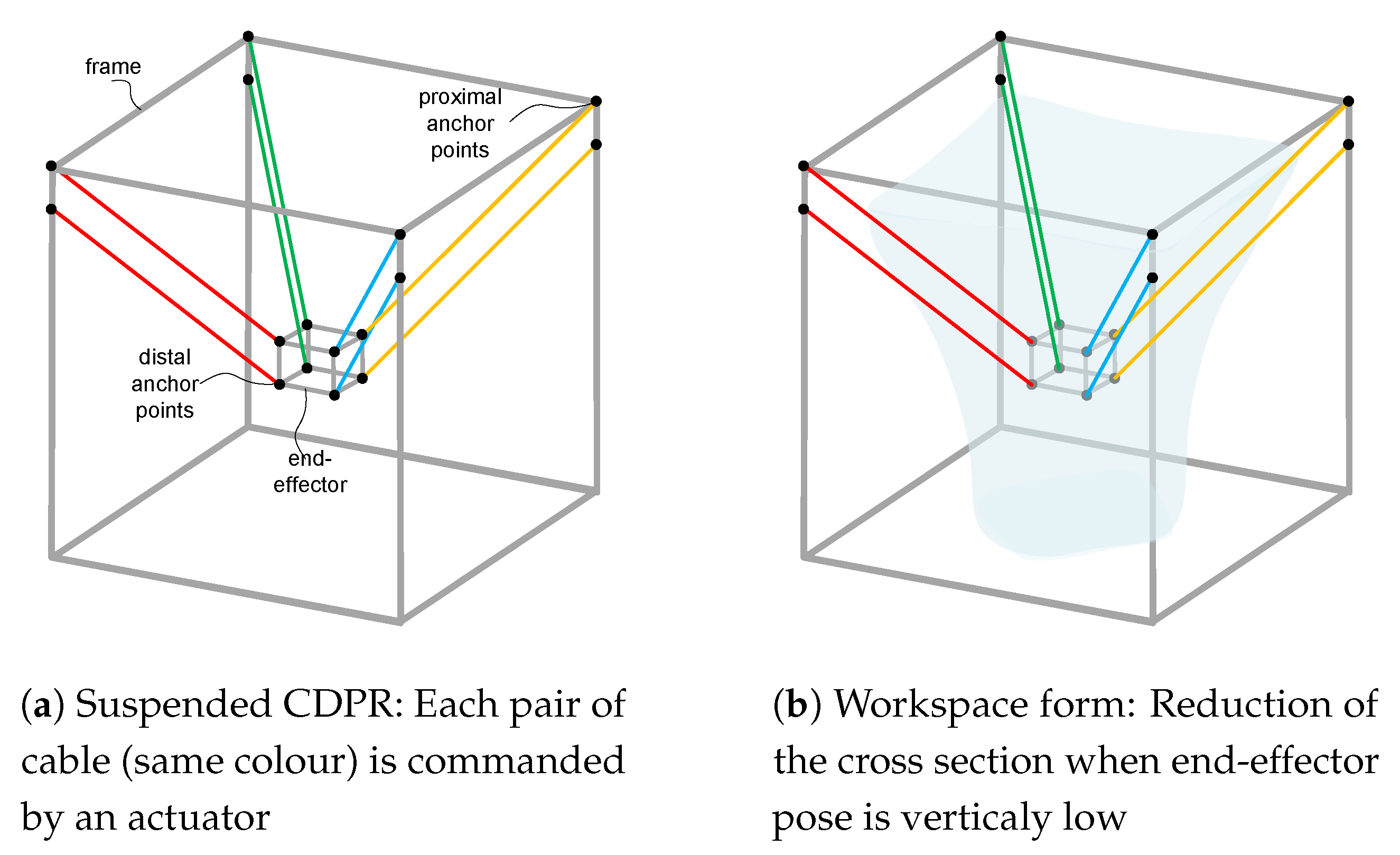
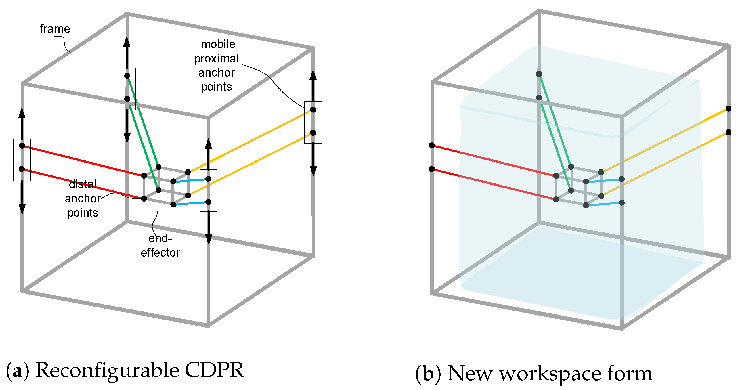
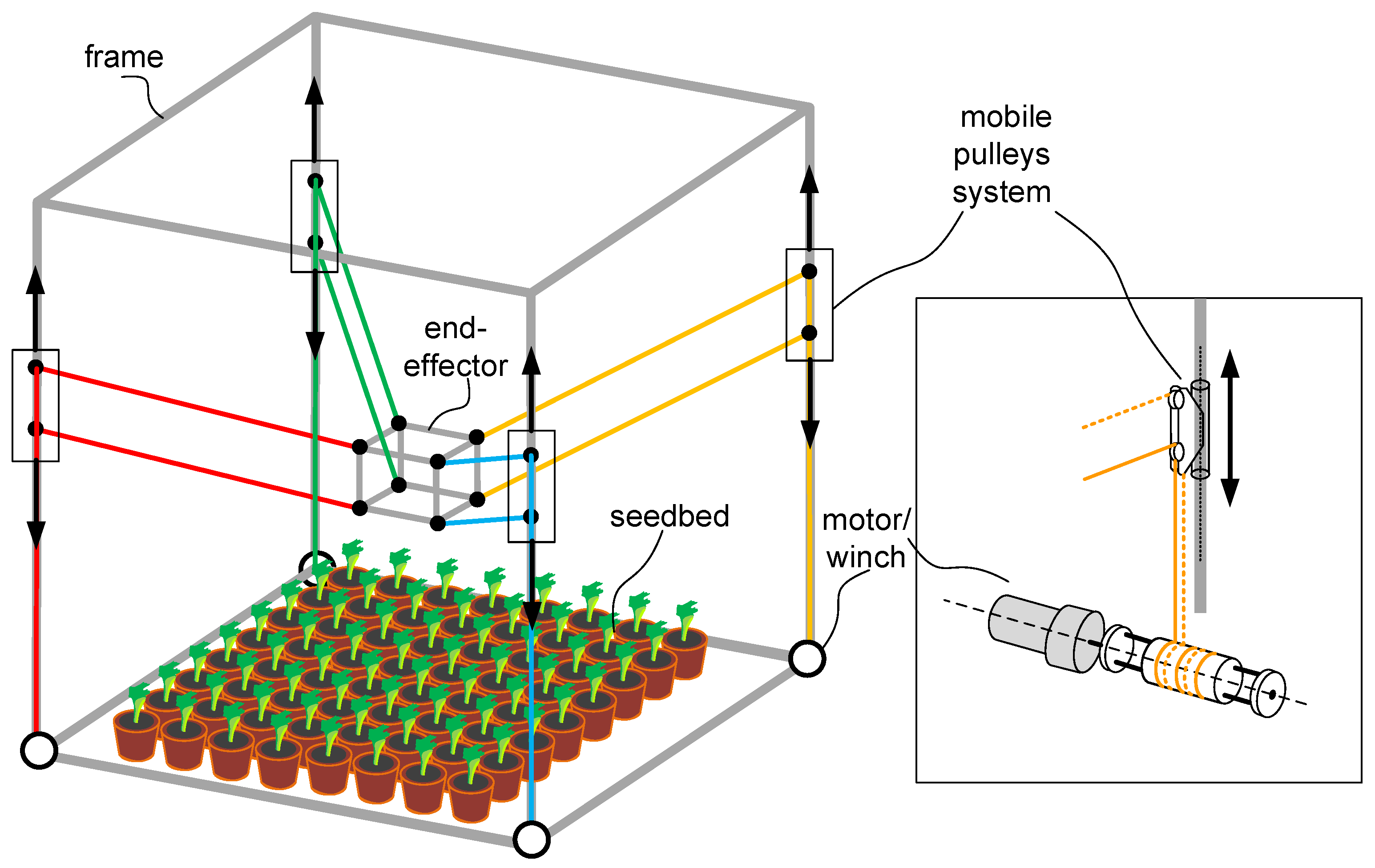
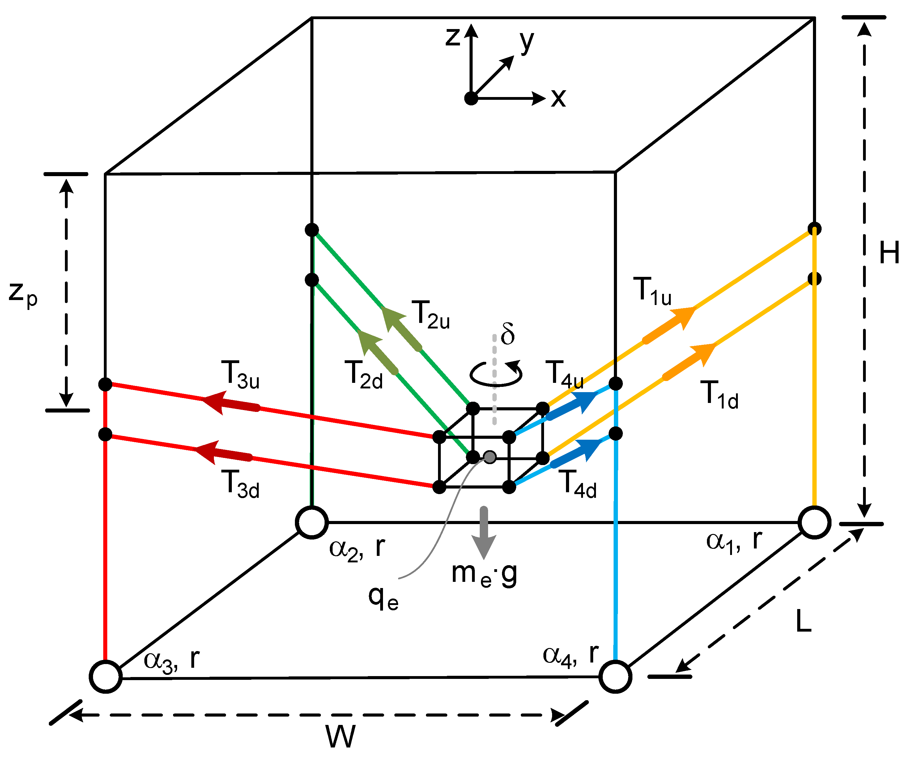
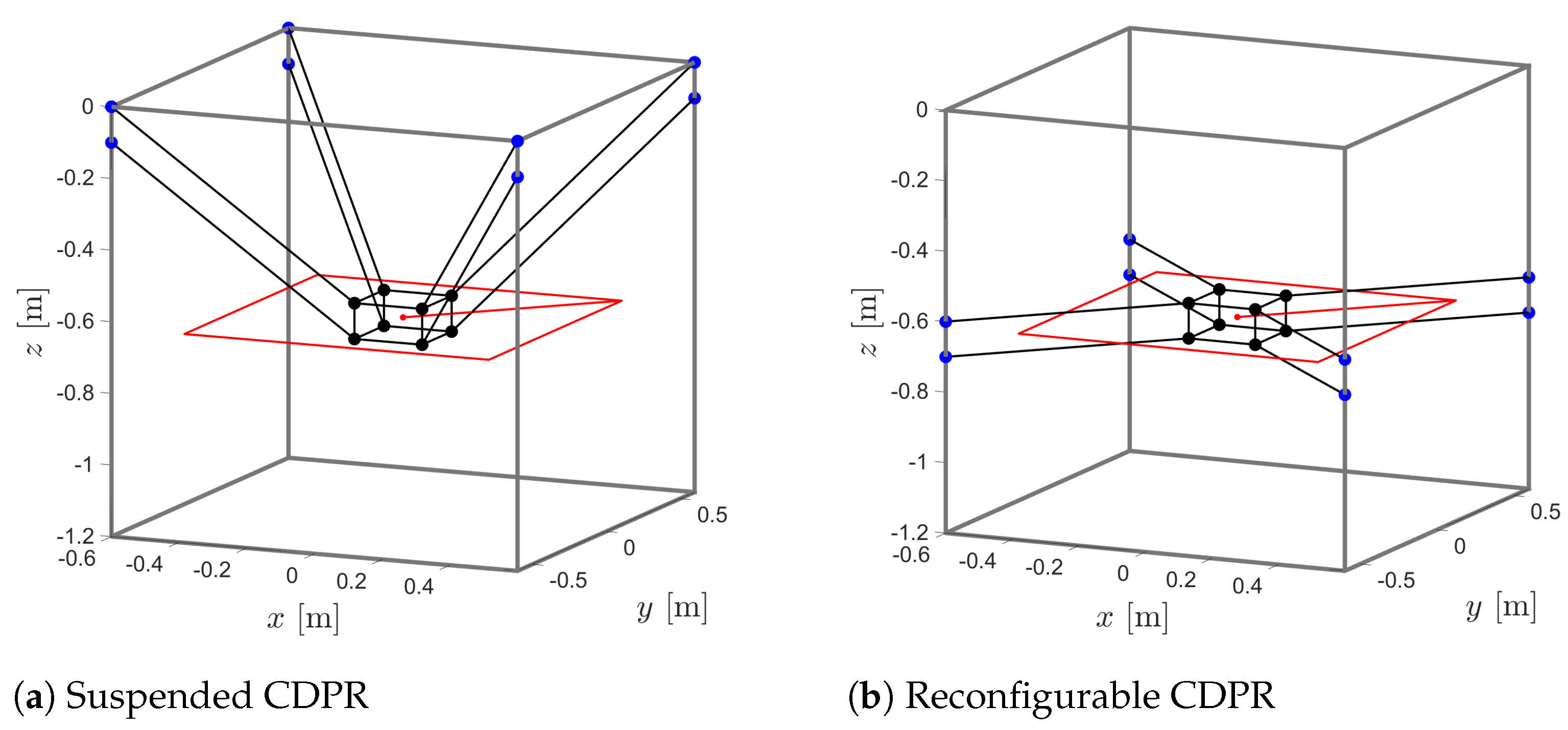
2. System Description

Cable-Driven Parallel Robots can be designed for both planar [18] and spatial configurations [19]. Depending on the number of cables and degrees-of-freedom of the mobile platform, these robots can have different configurations. The degrees-of-freedom in these robots determine the motion patterns of the end-effector, i.e., the positions and orientations of the end-effector within the workspace. This classifies CDPRs as restricted [20], under-constrained [21], or fully-constrained [22]. Furthermore, when all components are vertical or opposing gravity force in the cables, the configuration is called suspended [23].
The suspended configuration is achieved by keeping the cables under tension, distributed throughout the system to provide three-dimensional mobility to the end-effector. This suspended configuration offers greater flexibility and mobility by enabling movement in three-dimensional space. However, as mentioned earlier, the inability to ensure cable rigidity limits the workspace of the robot, as depicted in Figure 1, where a cable robot is suspended and its workspace are illustrated (see [24,25] for more details).
In this scheme, each pair of cables (coloured in red, green, blue and orange, respectively) are commanded by a motor. In this sense, the end-effector pose can be commanded by four motors, one for each pair of cables. As both cables of one motor remain parallel, the rotation of the end-effector is constrained in the horizontal plane and only its rotation over the vertical axis is allowed. In this way, four motors can command the four degrees-of-freedom of the end-effector. The scheme in Figure 1a was previously proposed in [24] and presents several advantages, such as the square form of the structural matrix of the robot (see more details in [24,26]).
Nevertheless, this novel configuration presented in [22] has a limited workspace and the reachable points of the end-effector are notoriously reduced when the end-effector is in the lower region of the frame (see Figure 2).
On the other hand, the automated tasks in crop production in a greenhouse requires a system with at least three translational degrees-of-freedom in a three-dimensional space. If the scheme in Figure 1 is used for agricultural automation, the required frame size should be much bigger than the terrain to be automated. Accordingly, the proposal of this paper modifies the scheme of Figure 1, adding a new degree-of-freedom that is able to synchronously move all the proximal anchor points (e.g., [27]). This allows the scheme to be applied to automated farming. Figure 3 represents this scheme together with its workspace.
This new degree-of-freedom allows for dynamically adjusting the position of the proximal anchor points of the robot, as shown in Figure 3a, allowing the movement of the end-effector in the area of highest tension of the cables. By keeping the robot at the maximum tensions or through this modification, we ensure greater stiffness, stability and a larger area of workspace (see Figure 3b), improving the robot’s accuracy and efficiency in interacting with the plants.
This strategy of keeping the robot at maximum tensions ensures not only greater control over its behavior and positioning, but also expands its effective workspace. The combination of an adaptable suspended configuration and the optimization of tensions by modifying the proximal anchor points will result in a highly efficient and accurate robot for agricultural applications in greenhouses. This design, supported by established principles of parallel robotics, is specifically adapted to improve interaction with the plants as they grow and with other greenhouse components, promoting automation and efficiency in the agricultural environment, see Figure 4.
The following sections detail the kinematic and dynamic models of the system for the simulated results.

3. Mathematical Model

The notation used for the mathematical formulation is shown in Figure 5 and Figure 6. The dimensions of the frame are denoted by L × W × H , while the dimensions of the end-effector are l × w × h . The tension in each pair of cables i is decomposed into T i = T i u + T i d , where T i u (upper cable) and T i d (lower cable) for i = 1 , , 4 , and the length of each cable is L i . The coordinates of the end-effector are expressed as q e = [ x e , y e , z e , δ ] T . The mass and rotational moment of inertia are m e and I e , respectively.
The joint coordinates are expressed as q α = [ α 1 , α 2 , α 3 , α 4 ] T , where α represents the joint coordinate of motor i. The angles that determine the cable direction i are referred to as ϕ i and θ i , as shown in Figure 6. Since the anchor points on the frame are denoted as F i = [ x f i , y f i , z f i ] T , and the anchor point on the end-effector as E i = [ x e i , y e i , z e i ] T , where z f i depends on z p representing the height of the pulley system’s anchor point on the frame, it adds an additional degree-of-freedom for robot reconfiguration.

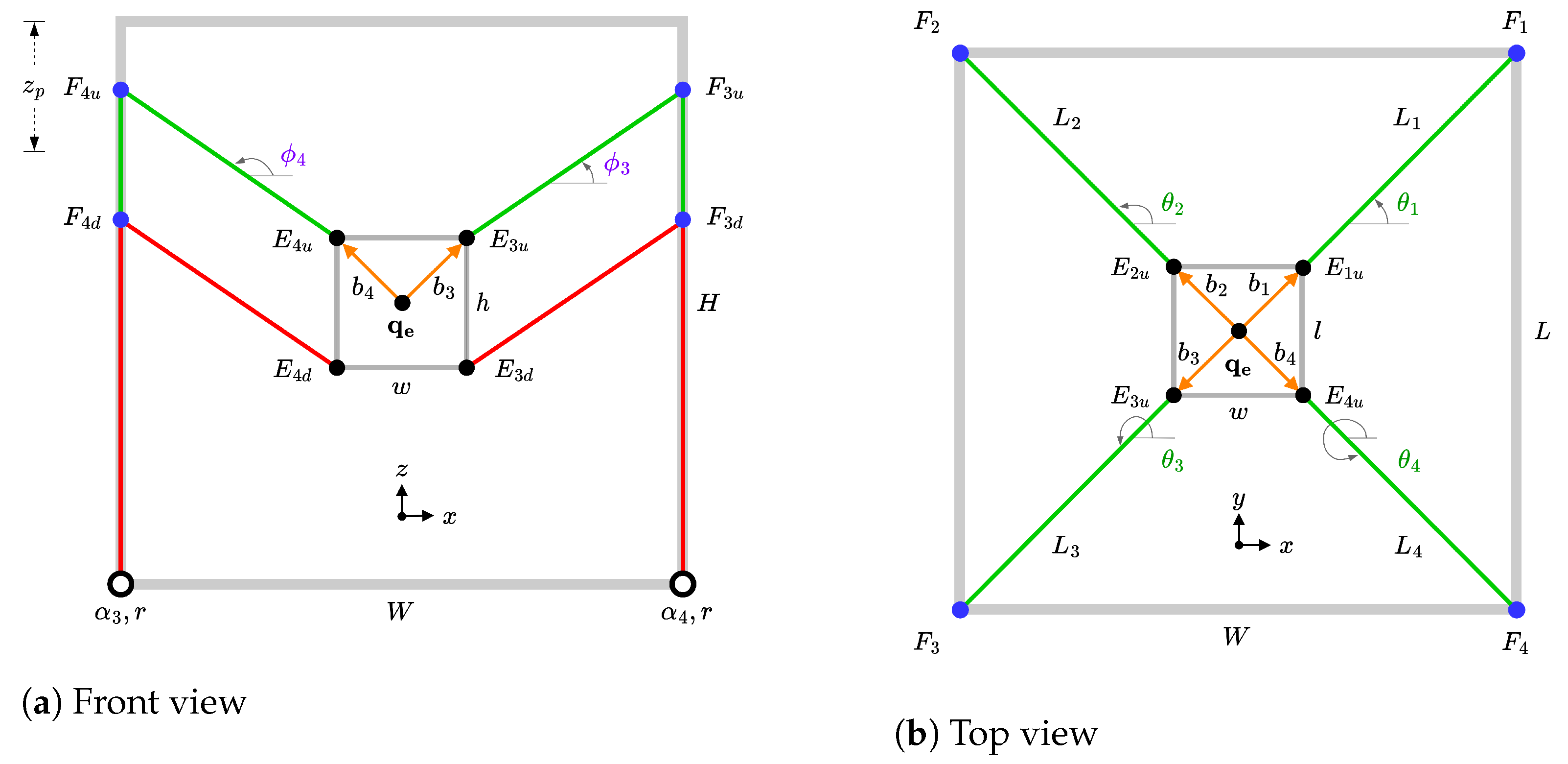
3.1. Kinematics and Statics
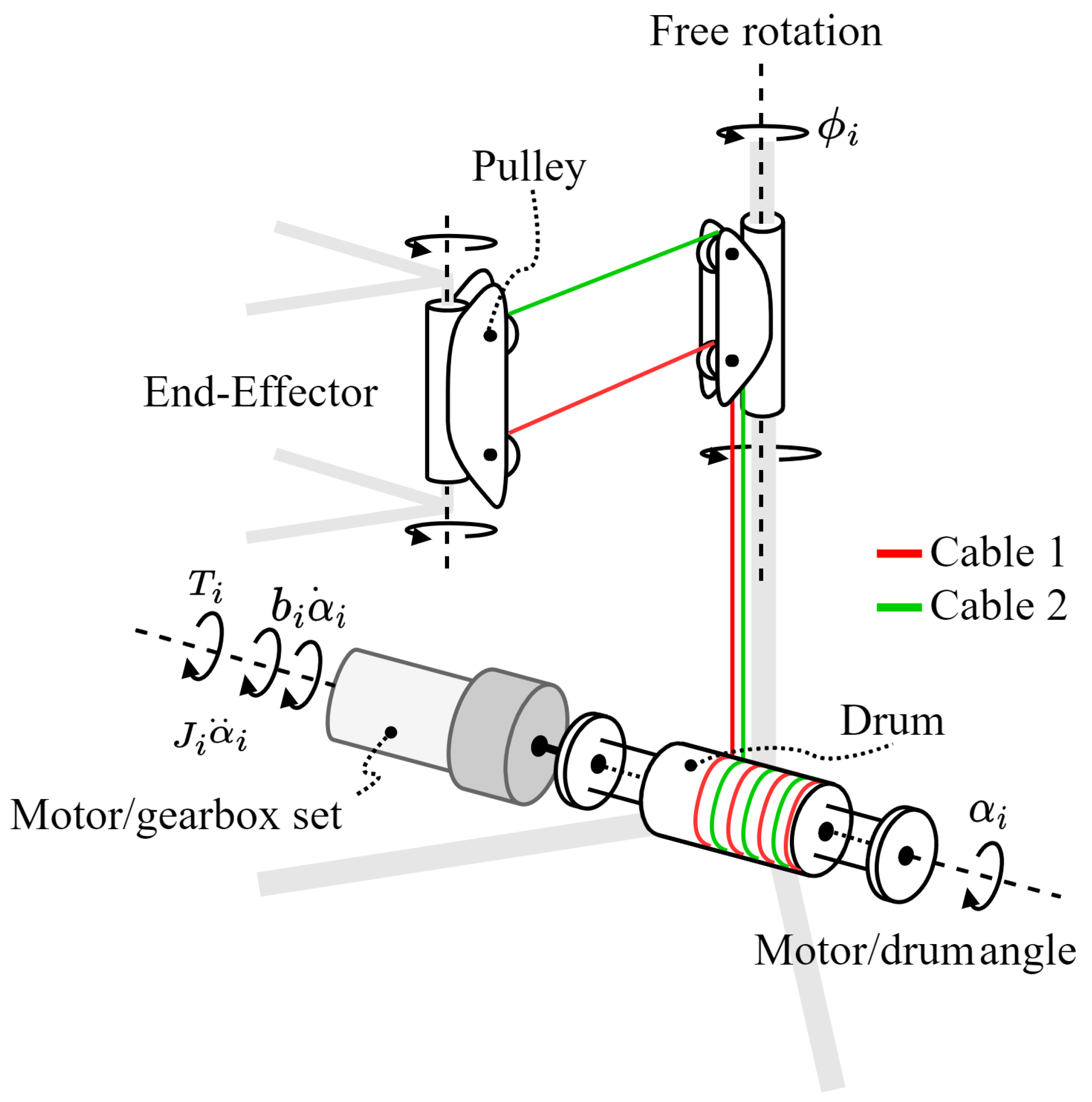
Inverse kinematics enables the determination of joint coordinates, denoted as q α , for a given end-effector position and orientation, q e , as well as a specified height for the proximal anchor point, z p . This inverse kinematics is necessary when implementing position control in the robot’s joint space. The expression for inverse kinematics, denoted as φ I K , can be formulated as follows:
q α = φ I K ( q e , z p )
Considering the initial cable lengths, denoted as L i 0 ( i = 1 , , 4 ), those associated with an arbitrary initial position of the end-effector without rotation, q e 0 = [ x e 0 , y e 0 , z e 0 , 0 ] T , and their respective distal anchor points, q e i 0 = [ x e i 0 , y e i 0 , z e i 0 , 0 ] T , the initial length of cable i can be expressed as follows:
L i 0 = F i E i 0 2
On the other hand, for an arbitrary end-effector position, the length of the cables is as follows:
L i = F i E i 2
Therefore, the necessary joint coordinates for a given end-effector position are
α i = 1 r L i L i 0
The complete expression of the inverse kinematics, φ I K , can be formulated as follows:
φ I K = ± 1 r Δ L
where ± is determined if the positive rotation of the motors implies an increase (+) or decrease (−) in the length of the cables and Δ L = [ L 1 L 1 0 , L 2 L 2 0 , L 3 L 3 0 , L 4 L 4 0 ] T , the expression (5) is a simple equation that determines the inverse kinematics of the robot.
On the other hand, the statics of the robot is determined by the force/torque balance of the end-effector (see e.g., [1]):
A T ( q e , z p ) T + W e = 0
where:
A T = u 1 u 4 R z ( δ ) b 1 × u 1 R z ( δ ) b 4 × u 4
where A T is the structure matrix, which is the transpose of the Jacobian matrix, T is the stress vector T = [ T 1 , T 2 , T 3 , T 4 ] T and W e are the external forces applied to the end-effector W e = [ 0 , 0 , m e · g , 0 ] T . The definition of the structure matrix uses the unit vectors containing the direction of the cables:
u i = L i L i 2
and the rotation matrix in the z-axis:
R z ( δ ) = cos ( δ ) sin ( δ ) 0 sin ( δ ) cos ( δ ) 0 0 0 1

3.2. Dynamics Model

The dynamic model of the robot can be determined by formulating the dynamics equation of the end-effector and the actuators. The proposal here is based on the reconfiguration of the proximal anchor points, which yields to high tension values in all cables. In addition, the mass of the end-effector is much bigger than the mass of the cables and the dynamic model can be therefore developed under the assumption of mass-less and rigid cables.
In regard to the actuators (comprising DC motor + gearbox + drum), the rotor inertia of motor i is denoted as J i , and the friction coefficient as ν i (see Figure 7).
The dynamics of the actuators can be expressed as
J α ¨ + ν α ˙ + r T = τ
and the end-effector by
M q ¨ e = A T ( q e , z p ) T + W e
where
M = m e 0 0 0 0 m e 0 0 0 0 m e 0 0 0 0 I e
By combining both equations, the resulting dynamic model of CDPR is
J α ¨ + ν α ˙ + r ( A T ) 1 M q ¨ e w e = τ
where, τ represents torque, J stands for the motor’s moment of inertia, ν denotes the motor’s viscous friction coefficient, r represents the spool radius, and T i corresponds to the tensions in each pair of cables.
The dynamic model (13) is expressed in joint coordinates α and can be directly applied for simulating the proposed CDPR and validating the control scheme for the end-effector position.

4. Simulation Results

In this section, simulated results obtained for a small prototype of the presented robot, whose specifications are summarized in Table 1, are presented. For the electro-mechanical part Maxon RE40 DC motors are used to directly drive the winches, with 26:1 gearboxes. The parameters of the actuators shown in Table 1 have been experimentally obtained by identifying their transfer function using their speed step responses [28]. Additionally, Dyneema fiber cable with a diameter of 0.66 mm and drums with an effective diameter of 40.10 mm are employed.
It should be pointed out that although some cable characteristics are presented in Table 1, the dynamic model of the cables is not developed as they are considered massless and inextensible (see [29]). The following subsections first present an analysis of the workspace according to the distribution of the robot cable forces. Subsequently, the dynamic model with kinematic control is simulated to demonstrate the viability of the proposal. The simulations are performed in Matlab® and Simulink®, using the kinematic and dynamic models obtained, and the parameters summarized in Table 1.

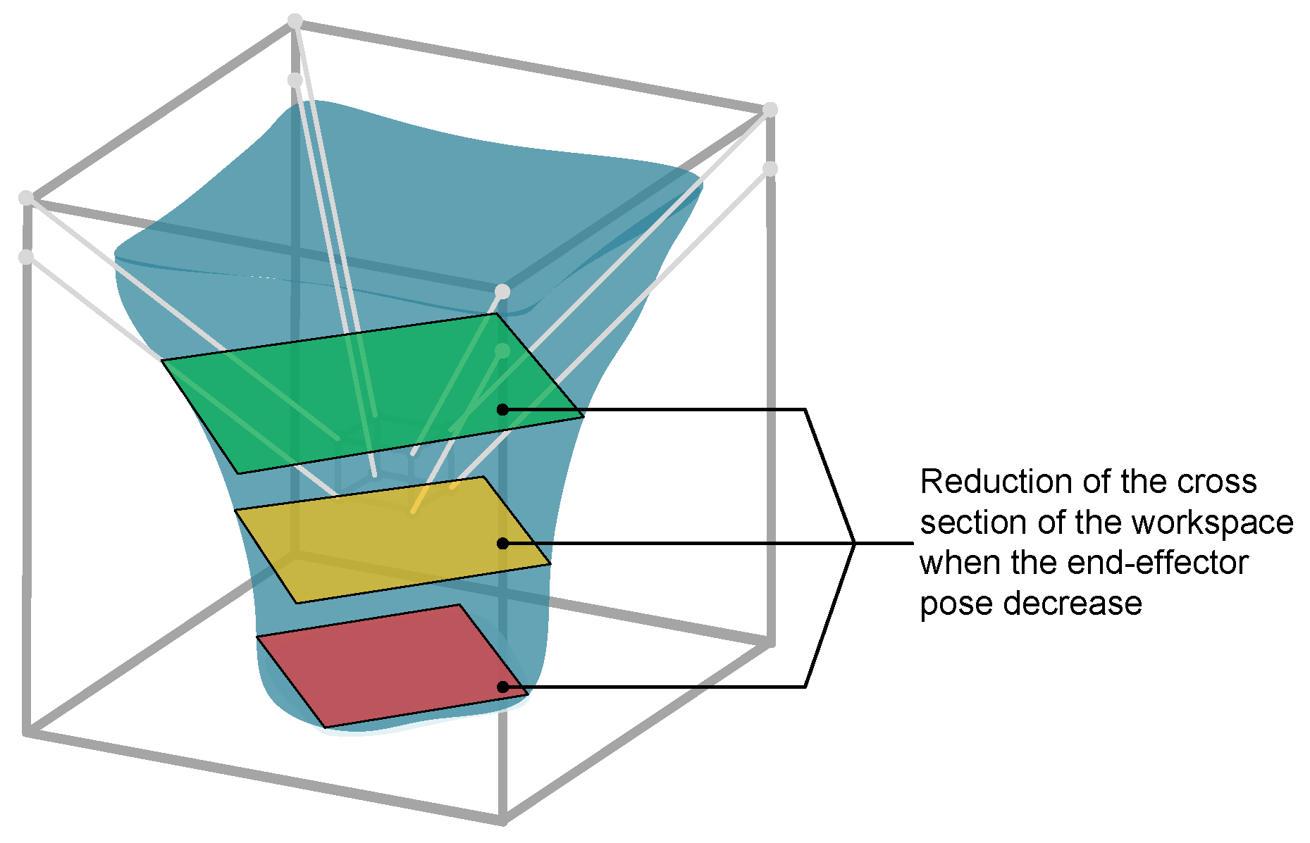
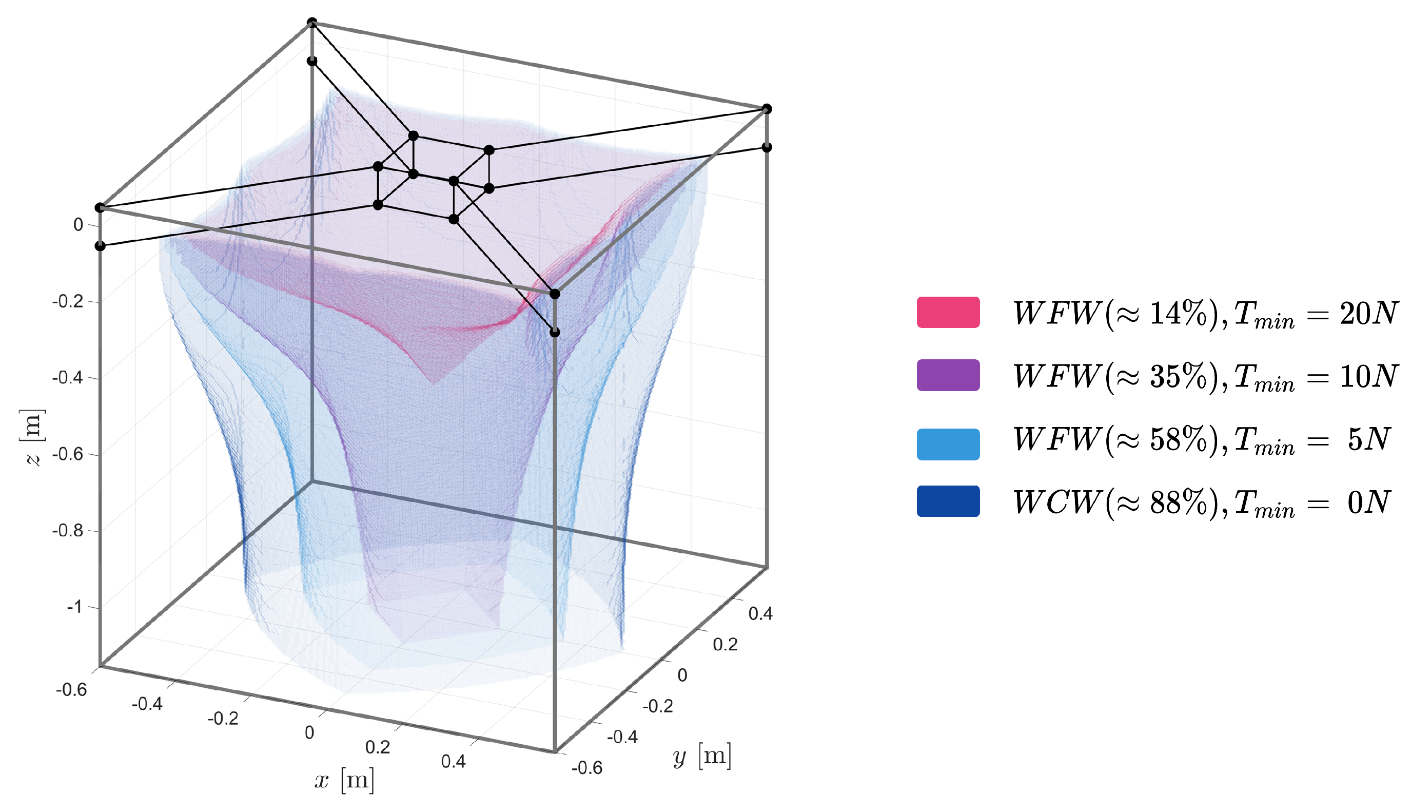
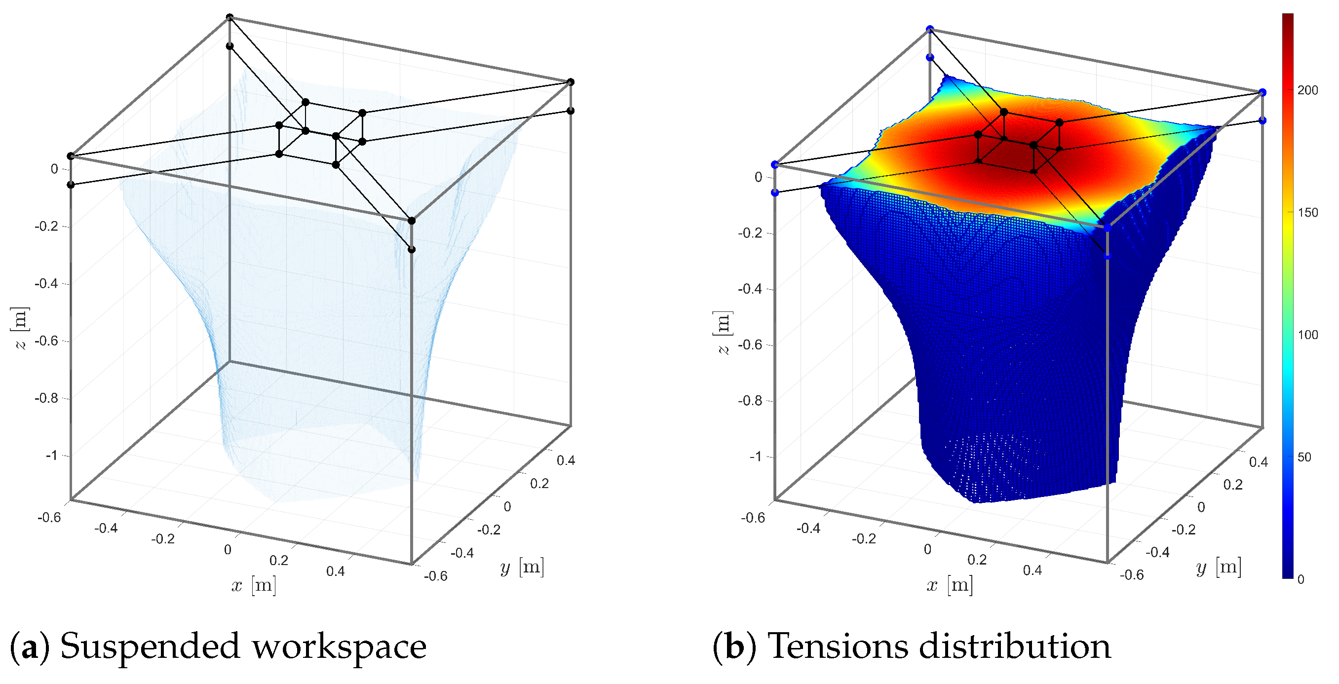
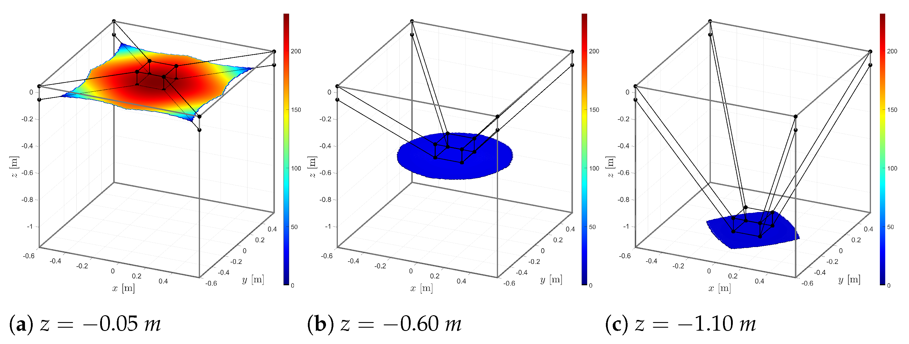
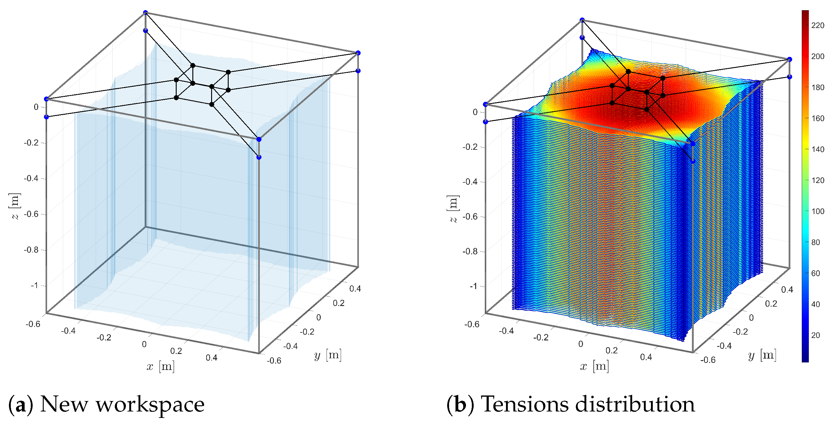
4.1. Workspace Analysis and Force Distributions

The tension distribution in CDPRs is a critical aspect, influencing various facets such as system equilibrium, workspace delineation, system rigidity, path control, and controller design. In tackling this issue, numerous mathematical methods and algorithms have been devised to compute cable tension distribution. One such approach is linear programming, wherein the optimal tension distribution is sought by minimizing the sum of tension forces, subject to specific constraints [30,31,32].
Another technique is non-linear programming, providing continuous tension distribution solutions along the joint trajectory. This employs programming with a quadratic objective function, facilitating continuous root force solutions and flexibility in the outcomes [33,34]. Moreover, closed-form methods have been developed to compute real-time tension distribution, optimizing the distance from the solution to a reference vector. These methods offer the advantage of reducing computation time while ensuring the continuity of the cables’ tension during continuous motion trajectories [35,36].
This method, known as Wrench-Feasible Workspace (WFW) [37,38], is defined as the set of end-effector poses where, for any external force applied to the end-effector, there exist positive tensions in the cables that maintain the end-effector in static equilibrium [39]. This definition emphasizes the importance of keeping the cables tense throughout the robot’s maneuvers, which is fundamental to its performance.
The robot workspace was obtained by solving the minimization problem in Equation (14) through static analysis based on a free-body diagram applied to the end-effector (see Figure 5 and Figure 6). To acheive this, if the values of T i are between the minimum and maximum forces, T m i n and T m a x , the position of the end-effector used is considered part of the viable workspace. A T ( q e , z p ) is calculated using the end-effector position q e and the height of the frame’s pulley systems, z p . Tensions are obtained using the pseudo-inverse of A T , which is the robot’s structure matrix.
min T T r e f subject to : A T ( q e , z p ) T + w e = 0 T m i n < T < T m a x
where T r e f is an arbitrary tension value within the tension range [ T m i n , T m a x ] .
Next, the volume changes in the robot workspace in the suspended-conventional configuration are presented. This considers the dimensions of the frame and end-effector (length, height, width), the weight of the end-effector, motor torque, drum diameter, and the minimum and maximum cable forces for calculating Equation (14) were determined to be between 10–1000 N. The closed workspace Wrench-Closure Workspace (WCW) was determined for a T m i n of 0 N, resulting in a working percentage of around 88%. Additionally, the Wrench-Feasible Workspace (WFW) was calculated for different minimum allowable tension values, as illustrated in Figure 8.
Taking the workspace of the robot in the conventional suspended configuration (fixed pulley system) with a permitted T m i n of 5 N as an example, characterized by its shape resembling an inverted cone (see Figure 9a), limiting within the defined tension range. The workspace reduces as the end-effector descends along the z-axis (around 58%). It is noticeable how cable tension is higher at the upper part of the workspace, the region with the highest cable tension (see Figure 9b).
Considering the simulation results of the conventional suspended robot, the robot has a larger flat area in workspace and stability when the cable stiffness is ensured (see Figure 10). With the movable proximal anchor points along the z-axis, a feasible workspace volume of 100% is obtained. The new workspace and tension distribution are shown in Figure 11.

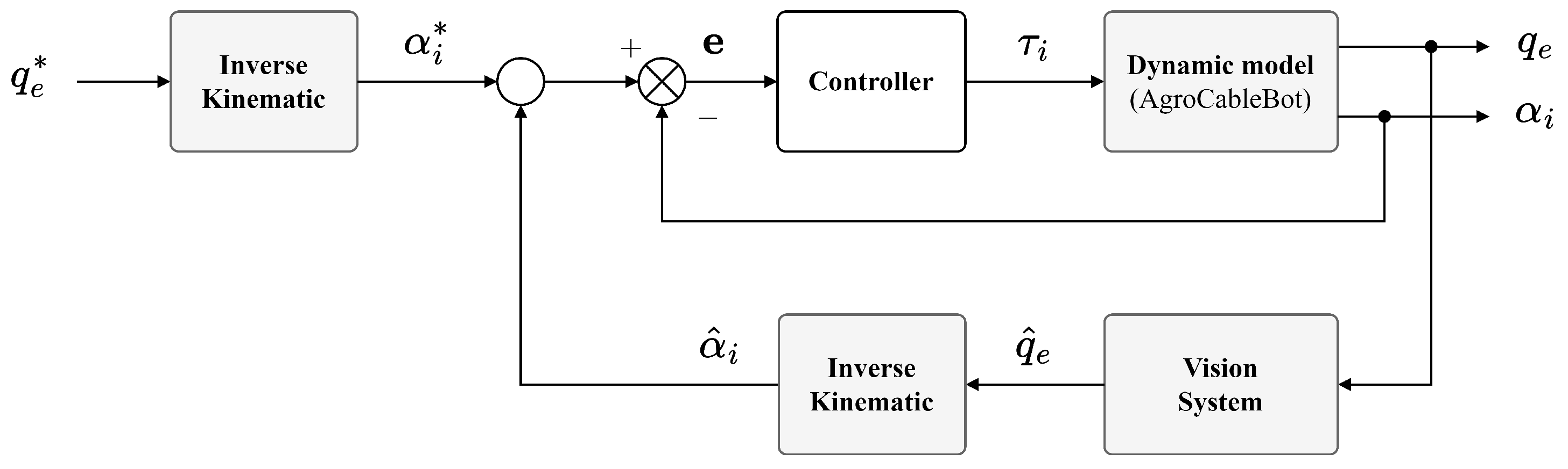
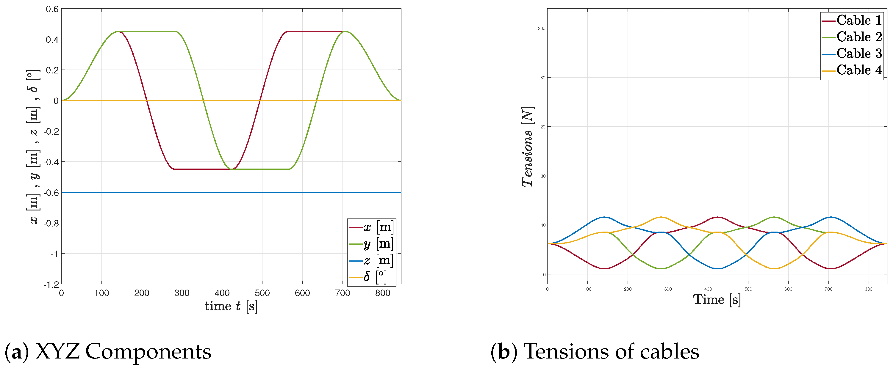
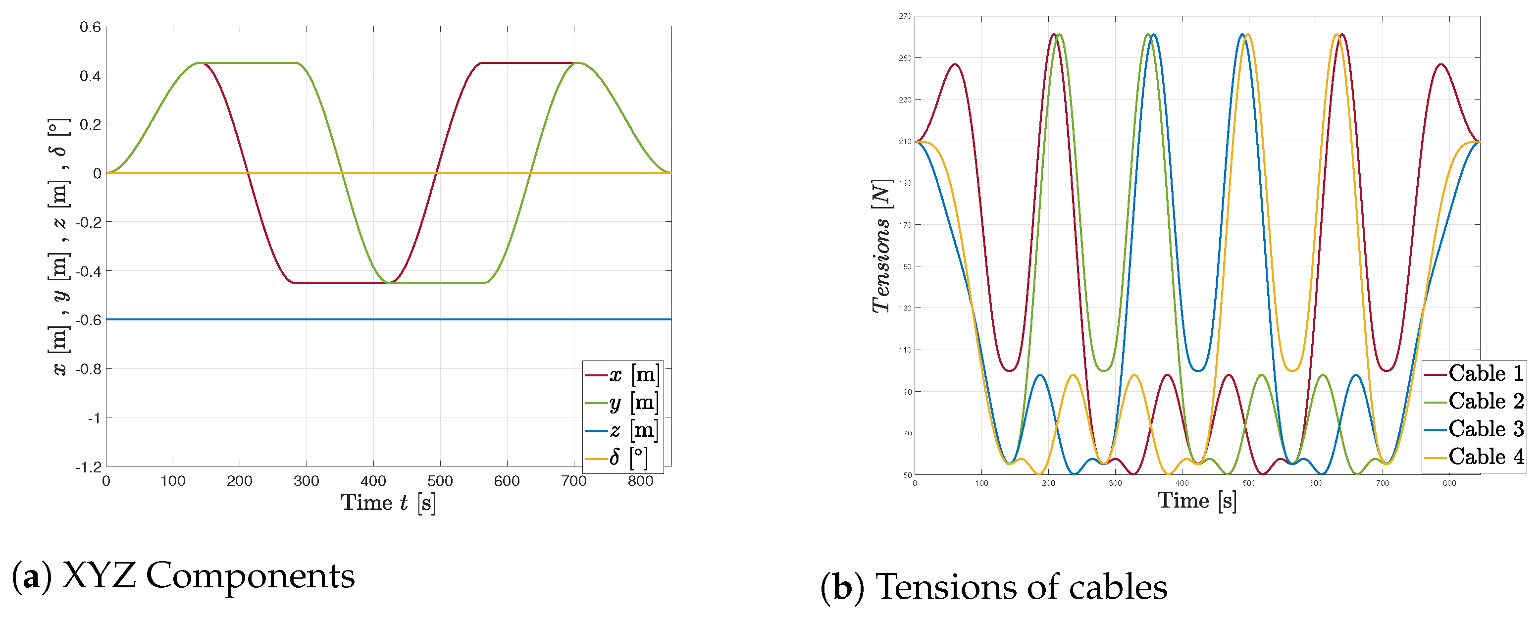
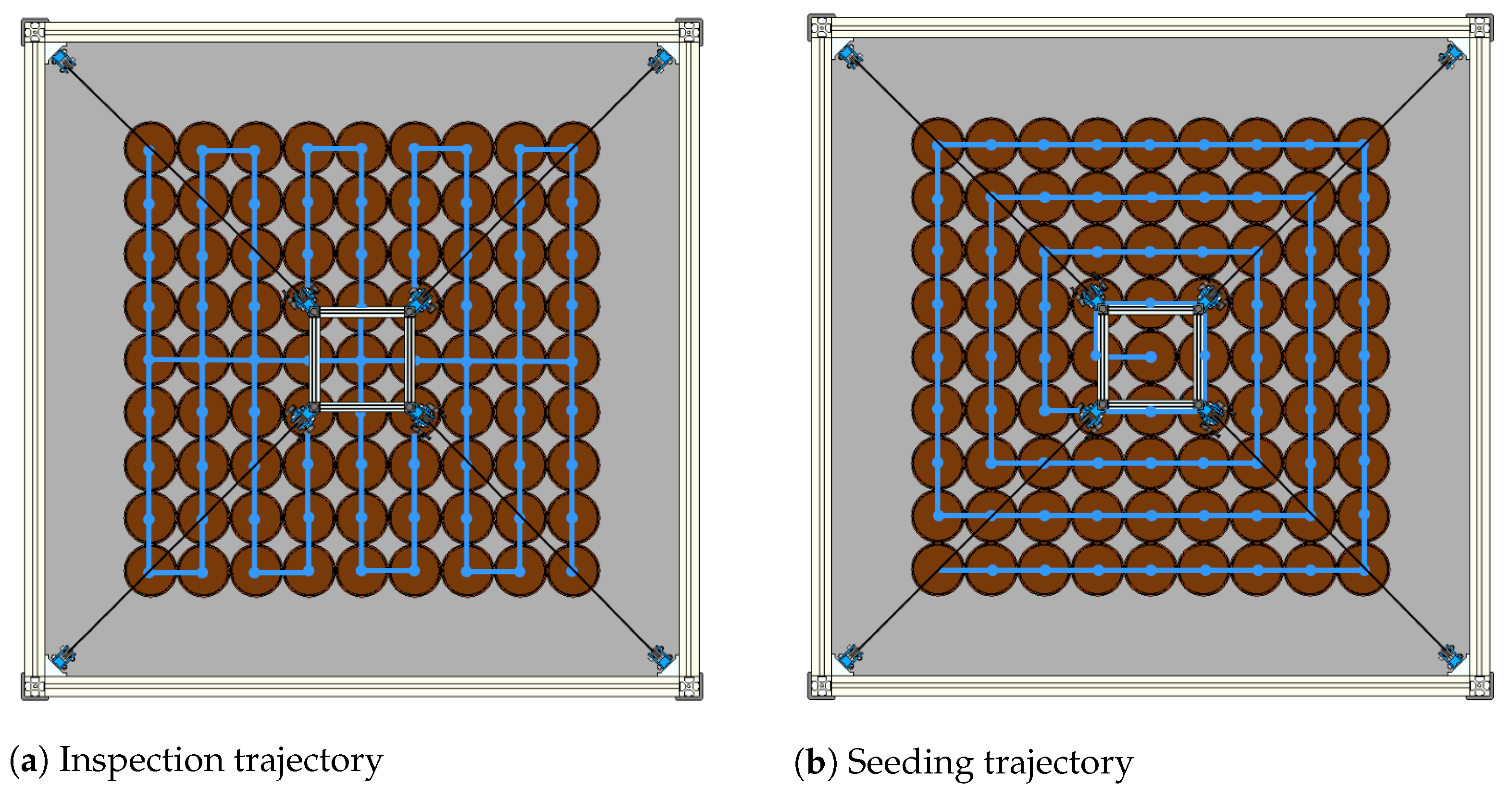
4.2. Control Scheme and Trajectories Generator

The control of the end-effector positioning can be performed in Cartesian coordinates q e = [ x e , y e , z e , δ ] T or in the joint coordinates α i = [ α 1 , α 2 , α 3 , α 4 ] T of the robot. The control scheme must allow the position and orientation of the end-effector q e to follow a desired trajectory q e * while maintaining cable tension within the allowed range [ T m i n , T m a x ] .
The AgroCableBot robot is controlled on the joint coordinates, α i , as shown in the feedback loop of the control scheme in Figure 12. Inverse kinematics is used to generate the joint coordinate references, α i * = [ α 1 * , α 2 * , α 3 * , α 4 * ] T . The controller block consists of a 4 × 4 diagonal array, with four controllers, each with a single input and a single output, tuned for each motor (see [40] for more details).
A supervisor feedback loop is used to estimate the position of the end-effector, q ^ e , through a computer vision system. This allows for estimating joint coordinates, α ^ i , and correcting positioning errors with the reference values calculated using inverse kinematics. In addition, this vision system allows for calibrating the end-effector at the home position (see [17,41] for more details).
For trajectory generation, temporal profiles with continuous and differentiable polynomials (cubic Bezier-splines) are used, allowing the calculation of velocity and acceleration at any point on the curve. This way, given the smoothness of the trajectory, there are no abrupt changes in motor acceleration or discontinuities in their rotation.
Figure 13 presents a square trajectory generated with a suspended (see Figure 13a) and reconfigured (see Figure 13b) CDPR configuration. This simulation is performed to compare the distribution of tensions in the cables during the generation of the trajectory. The trajectory was chosen so that the robot moves in different regions of the workspace.
Figure 14 and Figure 15 compares the simulation results of the conventional scheme and the reconfigurable one when the end-effector describes a square trajectory. Note that although the cartesian trajectories are similar (Figure 14a and Figure 15a) the resulting cable tensions are quite different (Figure 14b and Figure 15b). In the conventional scheme (non reconfigurable), the tension remains in the range [10–50] N and in the reconfigurable scheme, in [50–260] N.
In Figure 16, a schematic of two possible trajectories is shown to cover all rows of a seedbed with 81 pots arranged in a 9 × 9 matrix, spaced 100 mm from center to center. To do this, the end effector must start from its initial position and execute linear trajectories. In Figure 17 and Figure 18, the behavior of the robot trajectory components and the angles ( α i ) of the motors when generating the trajectory can be observed.
In Figure 19, a trajectory is presented where the end-effector not only positions itself at a particular seedling but also performs a movement along the z-axis to perform tasks such as seeding, spraying, fertilizer application, among others. In Figure 20, the behavior of the robot’s position and motor angles in the generation of trajectories that fulfill specific tasks is shown.

5. Conclusions

Suspended cable-driven parallel robots face a problem of instability and loss of tension in the cables due to their own configuration, which leads to errors in positioning and loss of workspace. To solve this problem, several studies have exploited various alternatives such as the incorporation of springs and the addition of more cables. In this work, it is proposed to give a synchronous translation motion to the pulley systems of the proximal anchor points of the robot along the z-axis, thus adding a new degree of freedom without losing the four degrees-of-freedom due to its configuration. This is an effective strategy to ensure tension distribution in the cables, obtain greater stability of motion of the mobile platform and guarantee a larger wrench-feasible workspace.
This proposed cable-driven robot configuration enhances the feasibility of utilizing them for greenhouse and urban garden automation, improving processes such as planting, spraying, and applying nutrients necessary for optimal plant growth. The key advantages lie in a system that efficiently carries out repetitive tasks with high precision, coupled with a design that prioritizes simplicity without compromising robustness. This enhancement further amplifies the merits and benefits of this robot type for agricultural applications. It not only facilitates the movement of the end-effector along the z-axis but also allows the pulley system to move along the z-axis as the plants grow.
As a perspective of this work, a first prototype of the AgroCableBot robot is being developed with experimental tests for end-effector calibration, trajectory generation and validation of the workspace with processes such as planting, irrigation and monitoring in a real crop.

Author Contributions

Conceptualization, A.G.-V. and F.J.C.-G.; methodology, A.G.-V.; software, A.G.-V., M.J.G.-B. and F.J.C.-G.; validation, A.G.-V. and M.J.G.-B.; investigation, A.G.-V. and M.J.G.-B.; writing original draft preparation, A.G.-V., M.J.G.-B., M.G.F. and F.J.C.-G.; supervision, M.G.F., F.J.C.-G. and A.G.-R.; project administration, A.G.-V. and M.J.G.-B.; funding acquisition, A.G.-V. and F.J.C.-G. All authors have read and agreed to the published version of the manuscript.

Funding

This research was funded by IMACUNA Research Hotbed of D+TEC Research Group of the University of Ibagué, Colombia and the University of Castilla-La Mancha (UCLM) in Toledo, Spain.

Data Availability Statement

Data is unavailable due to privacy restrictions.

Conflicts of Interest

The authors declare no conflict of interest.

Abbreviations

The following abbreviations are used in this manuscript:
CDPRCable-Driven Parallel Robot
WCWWrench-Closure Workspace
WFWWrench-Feasble Workspace

References

  1. Pott, A. Cable-Driven Parallel Robots: Theory and Application; Springer International Publishing: Berlin/Heidelberg, Germany, 2018; p. 475. [Google Scholar] [CrossRef]
  2. Hamann, M.; Nüsse, P.M.; Winter, D.; Ament, C. Towards a precise cable-driven parallel robot-a model-driven parameter identification enhanced by data-driven position correction. In Cable-Driven Parallel Robots. CableCon 2019; Springer: Berlin/Heidelberg, Germany, 2019; pp. 367–376. [Google Scholar] [CrossRef]
  3. Zhang, B.; Shang, W.; Cong, S.; Li, Z. Coordinated dynamic control in the task space for redundantly actuated cable-driven parallel robots. IEEE/ASME Trans. Mech. 2020, 26, 2396–2407. [Google Scholar] [CrossRef]
  4. Zi, B.; Duan, B.; Du, J.; Bao, H. Dynamic modeling and active control of a cable-suspended parallel robot. Mechatronics 2008, 18, 1–12. [Google Scholar] [CrossRef]
  5. Rasheed, T.; Long, P.; Caro, S. Wrench-feasible workspace of mobile cable-driven parallel robots. J. Mech. Robot. 2020, 12. [Google Scholar] [CrossRef]
  6. Tho, T.P.; Thinh, N.T. Using a Cable-Driven Parallel Robot with Applications in 3D Concrete Printing. Appl. Sci. 2021, 11, 563. [Google Scholar] [CrossRef]
  7. González-Rodríguez, A.; Martín-Parra, A.; Juárez-Pérez, S.; Rodríguez-Rosa, D.; Moya-Fernández, F.; Castillo-García, F.J.; Rosado-Linares, J. Dynamic Model of a Novel Planar Cable Driven Parallel Robot with a Single Cable Loop. Actuators 2023, 12, 200. [Google Scholar] [CrossRef]
  8. Castillo-Garcia, F.J.; Rubio-Gómez, G.; Juárez, S.; Rodríguez-Rosa, D.; Bravo, E.; Ottaviano, E.; Gonzalez-Rodriguez, A. Addition of passive-carriage for increasing workspace of cable robots: Automated inspection of surfaces of civil infrastructures. Smart Struct. Syst. Int. J. 2021, 27, 387–396. [Google Scholar]
  9. Mattioni, V.; Idà, E.; Carricato, M. Force-distribution sensitivity to cable-tension errors in overconstrained cable-driven parallel robots. Mech. Mach. Theory 2022, 175, 104940. [Google Scholar] [CrossRef]
  10. Izard, J.B.; Gouttefarde, M.; Michelin, M.; Tempier, O.; Baradat, C. A Reconfigurable Robot for Cable-Driven Parallel Robotic Research and Industrial Scenario Proofing. In Cable-Driven Parallel Robots; Springer: Berlin/Heidelberg, Germany, 2013; pp. 135–148. [Google Scholar] [CrossRef]
  11. Fedorov, D.; Birglen, L. Differential noncircular pulleys for cable robots and static balancing. J. Mech. Robot. 2018, 10, 061001. [Google Scholar] [CrossRef]
  12. Gueners, D.; Chanal, H.; Bouzgarrou, B.C. Design and implementation of a cable-driven parallel robot for additive manufacturing applications. Mechatronics 2022, 86, 102874. [Google Scholar] [CrossRef]
  13. Abbasnejad, G.; Tale-Masouleh, M. Optimal wrench-closure configuration of spatial reconfigurable cable-driven parallel robots. Proc. Inst. Mech. Eng. Part C J. Mech. Eng. Sci. 2021, 235, 4049–4056. [Google Scholar] [CrossRef]
  14. Li, C.; Huang, J.; Su, M.; Wu, D.; Xu, P.; Xie, Y.; Meng, F.; Wen, H.; Tian, H.; Duan, X. Reconfigurable cable-driven parallel robot with adjustable workspace towards positioning in neurosurgery: A preliminary design. In Proceedings of the 2021 IEEE International Conference on Real-time Computing and Robotics (RCAR), Xining, China, 15–19 July 2021; pp. 51–56. [Google Scholar] [CrossRef]
  15. Li, J.; Wang, K.; Wang, Y.; Wang, C. Motion Planning for a Cable-Driven Lower Limb Rehabilitation Robot with Movable Distal Anchor Points. J. Bionic Eng. 2023, 20, 1585–1596. [Google Scholar] [CrossRef]
  16. Cui, Z.; Tang, X. Analysis of stiffness controllability of a redundant cable-driven parallel robot based on its configuration. Mechatronics 2021, 75, 102519. [Google Scholar] [CrossRef]
  17. García-Vanegas, A.; Leiton-Murcia, C.; Forero, M.G.; Gonzalez-Rodríguez, A.; Castillo-García, F. Cable-Driven Parallel Robot Controlled by Servo-Vision System. In Pattern Recognition. MCPR 2022; Springer: Berlin/Heidelberg, Germany, 2022; pp. 291–302. [Google Scholar] [CrossRef]
  18. Mattioni, V.; Ida’, E.; Carricato, M. Design of a planar cable-driven parallel robot for non-contact tasks. Appl. Sci. 2021, 11, 9491. [Google Scholar] [CrossRef]
  19. Tourajizadeh, H.; Yousefzadeh, M.; Khalaji, A.K.; Bamdad, M. Design, modeling and control of a simulator of an aircraft maneuver in the wind tunnel using cable robot. Int. J. Control Autom. Syst. 2022, 20, 1671–1681. [Google Scholar] [CrossRef]
  20. Hwang, S.W.; Bak, J.H.; Yoon, J.; Park, J.H. Oscillation reduction and frequency analysis of under-constrained cable-driven parallel robot with three cables. Robotica 2020, 38, 375–395. [Google Scholar] [CrossRef]
  21. Youssef, K.; Otis, M.J.D. Reconfigurable fully constrained cable driven parallel mechanism for avoiding interference between cables. Mech. Mach. Theory 2020, 148, 103781. [Google Scholar] [CrossRef]
  22. Gouttefarde, M.; Krut, S.; Company, O.; Pierrot, F.; Ramdani, N. On the design of fully constrained parallel cable-driven robots. In Advances in Robot Kinematics: Analysis and Design; Springer: Berlin/Heidelberg, Germany, 2008; pp. 71–78. [Google Scholar]
  23. Paty, T.; Binaud, N.; Wang, H.; Segonds, S. Sensitivity Analysis of a Suspended Cable-Driven Parallel Robot to Design Parameters. J. Mech. Robot. 2023, 15, 061001. [Google Scholar] [CrossRef]
  24. Castelli, G.; Ottaviano, E.; González, A. Analysis and simulation of a new Cartesian cable-suspended robot. Proc. Inst. Mech. Eng. Part C J. Mech. Eng. Sci. 2010, 224, 1717–1726. [Google Scholar] [CrossRef]
  25. Gonzalez-Rodriguez, A.; Castillo-Garcia, F.; Ottaviano, E.; Rea, P.; Gonzalez-Rodriguez, A. On the effects of the design of cable-Driven robots on kinematics and dynamics models accuracy. Mechatronics 2017, 43, 18–27. [Google Scholar] [CrossRef]
  26. Castillo-Garcia, F.; Rea, P.; Gonzalez-Rodriguez, A.; Ottaviano, E. On the Design of a 4 Degrees-of-Freedom Pick and Place Cable Suspended Parallel Manipulator. Int. J. Robot. Autom. (IJRA) 2017, 6, 286–302. [Google Scholar] [CrossRef]
  27. An, H.; Yuan, H.; Tang, K.; Xu, W.; Wang, X. A Novel Cable-Driven Parallel Robot With Movable Anchor Points Capable for Obstacle Environments. IEEE/ASME Trans. Mechatr. 2022, 27, 5472–5483. [Google Scholar] [CrossRef]
  28. Wu, W. DC motor identification using speed step responses. In Proceedings of the 2010 American Control Conference, Baltimore, MD, USA, 30 June–2 July 2010; pp. 1937–1941. [Google Scholar]
  29. Ottaviano, E.; Castelli, G. A study on the effects of cable mass and elasticity in cable-based parallel manipulators. In ROMANSY 18 Robot Design, Dynamics and Control: Proceedings of The Eighteenth CISM-IFToMM Symposium; Springer: Berlin/Heidelberg, Germany, 2010; pp. 149–156. [Google Scholar]
  30. Shiang, W.J.; Cannon, D.; Gorman, J. Optimal force distribution applied to a robotic crane with flexible cables. In Proceedings of the 2000 ICRA. Millennium Conference. IEEE International Conference on Robotics and Automation. Symposia Proceedings (Cat. No.00CH37065), San Francisco, CA, USA, 24–28 April 2002; Volume 2, pp. 1948–1954. [Google Scholar] [CrossRef]
  31. Pham, C.B.; Yang, G.; Yeo, S.H. Dynamic analysis of cable-driven parallel mechanisms. In Proceedings of the 2005 IEEE/ASME International Conference on Advanced Intelligent Mechatronics, Monterey, CA, USA, 24–28 July 2005; pp. 612–617. [Google Scholar] [CrossRef]
  32. Oh, S.R.; Agrawal, S. Cable suspended planar robots with redundant cables: Controllers with positive tensions. IEEE Trans. Robot. 2005, 21, 457–465. [Google Scholar] [CrossRef]
  33. Borgstrom, P.H.; Jordan, B.L.; Sukhatme, G.S.; Batalin, M.A.; Kaiser, W.J. Rapid Computation of Optimally Safe Tension Distributions for Parallel Cable-Driven Robots. IEEE Trans. Robot. 2009, 25, 1271–1281. [Google Scholar] [CrossRef]
  34. Agahi, M.; Notash, L. Redundancy Resolution of Wire-Actuated Parallel Manipulators. Trans. Can. Soc. Mech. Eng. 2009, 33, 561–573. [Google Scholar] [CrossRef]
  35. Berti, A. Kinematics and Statics of Cable-Driven Parallel Robots by Interval-Analysis-Based Methods. Ph.D. Thesis, Universitá Degli Studi di Bologna, Bologna, Italy, 2015. [Google Scholar] [CrossRef]
  36. Diao, X.; Ma, O.; Lu, Q. Singularity Analysis of Planar Cable-Driven Parallel Robots. In Proceedings of the 2008 IEEE Conference on Robotics, Automation and Mechatronics, Chengdu, China, 21–24 September 2008; pp. 272–277. [Google Scholar] [CrossRef]
  37. Pott, A.; Bruckmann, T.; Mikelsons, L. Closed-form Force Distribution for Parallel Wire Robots. In Computational Kinematics: Proceedings of the 5th International Workshop on Computational Kinematics; Kecskeméthy, A., Müller, A., Eds.; Springer: Berlin/Heidelberg, Germany, 2009; pp. 25–34. [Google Scholar] [CrossRef]
  38. Gouttefarde, M.; Merlet, J.P.; Daney, D. Determination of the wrench-closure workspace of 6-DOF parallel cable-driven mechanisms. In Advances in Robot Kinematics: Mechanisms and Motion; Lennarčič, J., Roth, B., Eds.; Springer: Dordrecht, Germany, 2006; pp. 315–322. [Google Scholar] [CrossRef]
  39. Bolboli, J.; Khosravi, M.A.; Abdollahi, F. Stiffness feasible workspace of cable-driven parallel robots with application to optimal design of a planar cable robot. Robot. Auton. Syst. 2019, 114, 19–28. [Google Scholar] [CrossRef]
  40. Juárez-Pérez, S.; Martín-Parra, A.; Arena, A.; Ottaviano, E.; Gattulli, V.; Castillo-García, F.J. Dynamic Control of a Novel Planar Cable-Driven Parallel Robot with a Large Wrench Feasible Workspace. Actuators 2022, 11, 367. [Google Scholar] [CrossRef]
  41. García-Vanegas, A.; Liberato-Tafur, B.; Forero, M.G.; Gonzalez-Rodríguez, A.; Castillo-García, F. Automatic Vision Based Calibration System for Planar Cable-Driven Parallel Robots. In Pattern Recognition and Image Analysis; Morales, A., Fierrez, J., Sánchez, J.S., Ribeiro, B., Eds.; Springer: Cham, Switzerland, 2019; pp. 600–609. [Google Scholar] [CrossRef]
Figure 1. (a) Scheme and (b) workspace of suspended CDPR configuration.
Robotics 12 00165 g001
Figure 2. Cross-section reduction of the suspended CDPR presented in [24].
Robotics 12 00165 g002
Figure 3. (a) Scheme and (b) workspace of suspended CDPR with mobile pulleys system in frame.
Robotics 12 00165 g003
Figure 4. Experimental setup of the cable robot AgroCableBot with eight cables.
Robotics 12 00165 g004
Figure 5. Statics of AgroCableBot robot with eight cables for mathematical model.
Robotics 12 00165 g005
Figure 6. (a) Front and (b) top view of schematic of AgroCableBot robot. Green cables correspond to the upper ones and red cables to the lower ones.
Robotics 12 00165 g006
Figure 7. Dynamic model of AgroCableBot winch with inertial parameters.
Robotics 12 00165 g007
Figure 8. Comparison of the workspace of AgroCableBot computed with pseudo-inverse method for T m i n = { 0 , 5 , 10 , 20 } N.
Robotics 12 00165 g008
Figure 9. (a) Workspace and (b) tensions distribution with T m i n = 5 N of Suspended CDPR.
Robotics 12 00165 g009
Figure 10. Tensions distributions in different height, z = 0.05 , 0.60 , 1.10 m, of suspended CDPR.
Robotics 12 00165 g010
Figure 11. (a) Workspace and (b) tensions distribution with T m i n = 5 N of robot AgroCableBot with mobile pulley system in the frame.
Robotics 12 00165 g011
Figure 12. Kinematic control for robot AbroCableBot.
Robotics 12 00165 g012
Figure 13. Generation of a square trajectory (in red) with (a) Suspended and (b) Reconfigurable CDPR. Blue points are the proximal anchor points and black ones the distal anchor points.
Robotics 12 00165 g013
Figure 14. Simulation of tracking move of a square trajectory with a suspended CDPR.
Robotics 12 00165 g014
Figure 15. Simulation of tracking move of a square trajectory with a reconfigurable CDPR.
Robotics 12 00165 g015
Figure 16. Upper view of the simulation of tracking of AgroCableBot Robot. Blue lines are the planar trajectories for inspection and seeding tasks.
Robotics 12 00165 g016
Figure 17. Generation of trajectory for inspection of seedlings in seedbeds.
Robotics 12 00165 g017
Figure 18. Tracking move of AgroCableBot Robot.
Robotics 12 00165 g018
Figure 19. Generation of trajectory for seeding of seedlings in seedbeds.
Robotics 12 00165 g019
Figure 20. Tracking move of AgroCableBot Robot.
Robotics 12 00165 g020
Table 1. Parameters of the AgroCableBot robot.
ParameterValueUnit
Frame (fixed platform)
  Length, L1.2m
  Width, W1.2m
  Height, H1.2m
End-Effector (mobile platform)
  Length, l0.2m
  Width, w0.2m
  Height, h0.1m
  Mass, m5kg
  Rotational Inertia, I e 14.36 · 10 3 kg ·m 2
Cable and drum
  Cable diameter0.66mm
  Type of cableDyneema, SS250G-1500-
  Drum effective radius, r40.10mm
Actuators
  Rotational Inertia, J 2.30 · 10 4 kg ·m 2
  Viscous friction coefficient, ν 1.45 · 10 2 N·ms
  Gear transmission, n26:1-
Disclaimer/Publisher’s Note: The statements, opinions and data contained in all publications are solely those of the individual author(s) and contributor(s) and not of MDPI and/or the editor(s). MDPI and/or the editor(s) disclaim responsibility for any injury to people or property resulting from any ideas, methods, instructions or products referred to in the content.

