
Industrial Robots in Mechanical Machining: Perspectives and Limitations

 , , ,
, , ,  and
and 
Abstract
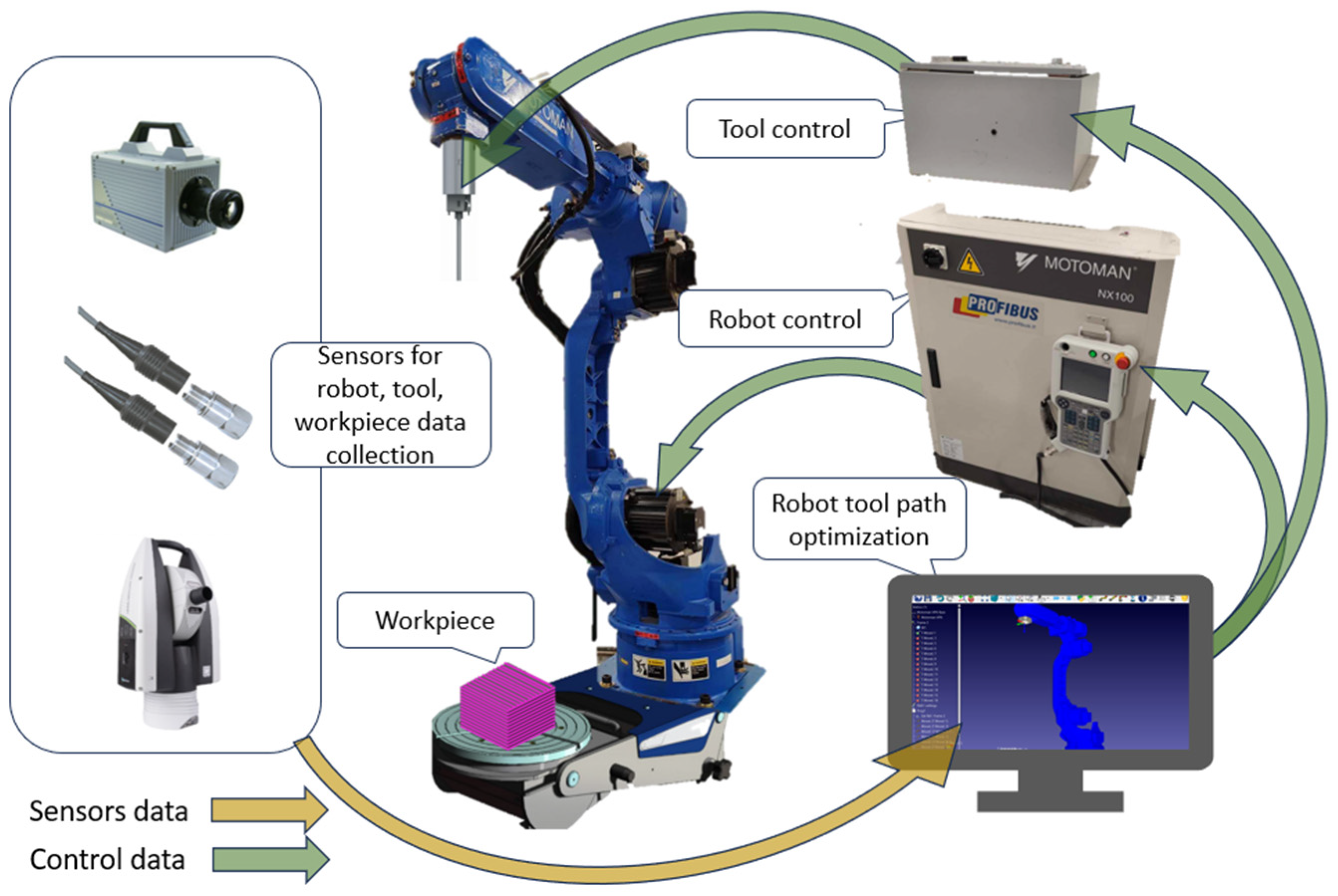
:1. Introduction
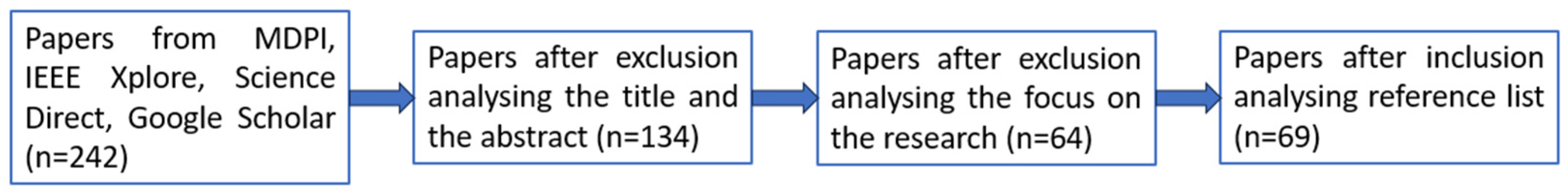
2. Method for the Selection Process
- is focused on industrial robots;
- is focused on robotic posture and path planning;
- is focused on machining processes where forces act;
- is focused on sensors and their data fusion;
- is focused on robotic control;
- is focused on machine learning adaptations.
- articles older than five years are excluded, with some exceptions after reviewing reference lists;
- the articles are not fully accessible;
- articles not specifically focusing on industrial robots or data gathering were not selected;
- articles providing information about industrial robot manipulation and packing;
- articles providing insufficient data related to the manuscript.
3. Robotic Material Processing
3.1. Milling

| Problem | Methods | Industrial Robot | Additional Means | Ref. |
|---|---|---|---|---|
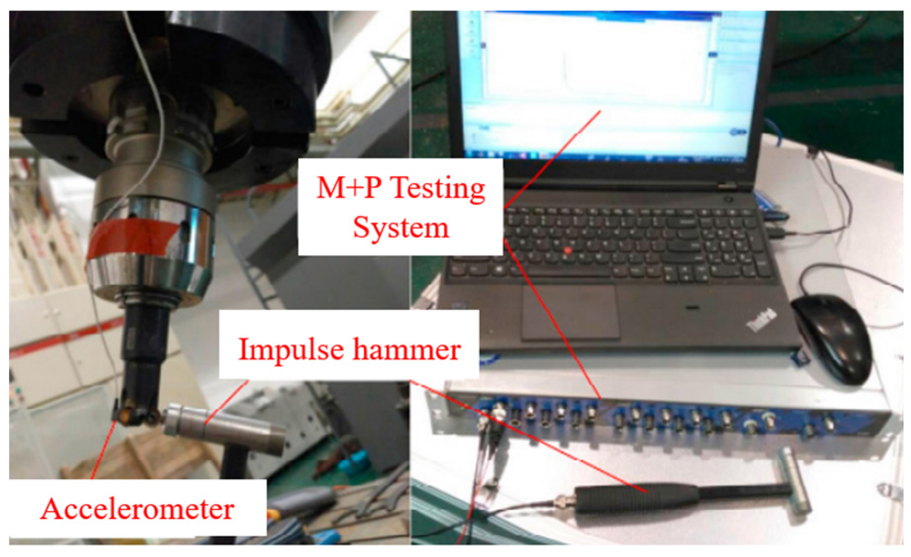
| Low stiffness of the robot structure | Impact tests at many tool-tip positions to obtain modal parameters of frequency response functions (FRFs) | ABB IRB 6660-205 | Sound microphone, National Instruments (NI) data acquisition system | [17] |
| Optimal control for active vibration suppression | Linear Quadratic Regulator (LQR) optimal control | KUKA KR500-3 with KUKA KRC4 controller | KUKA Robotic Sensor Interface and EtherCAT protocol, laser tracker | [18] |
| Machining accuracy based on stiffness properties | Task-dependent performance index (PI) | ABB IRB 6660-205 | NI data acquisition the system, laser tracker, dynamometer | [19] |
| Stiffness increase and machining accuracy improvement | Conversion from a 5-axis CNC tool path to a 6-axis industrial robot trajectory | Motoman MH80 IR | AT960 laser tracker, NX 8.5 software, Leitz PMM-XI8106 | [20] |
| Avoidance of over-cut and interference | Fixed cutter axis control (F-CAC) | Motoman-UP6 | MATLAB-based design and simulation toolbox and ROTSY 4.2 software | [21] |
| Prediction of surface topography | Mapping-based intersecting method | ABB IRB 6660-205 | Kistler dynamometer, microphone, acceleration sensor. | [14] |
3.2. Grinding
3.3. Polishing
3.4. Drilling
3.5. Other Cases
4. Robot Path and Posture Planning
4.1. Robot Path Planning
4.2. Robot Posture Planning
5. Advanced Robotic Technologies
5.1. Advanced Control
5.2. Robotic Sensing
5.3. Machine Learning Based Adaptive Solutions
6. Discussion
- Robotic machining cases, robotic tool path and posture planning, advanced robotic technologies such as control, sensing, and machine learning, and robotic material processing technologies were qualitatively evaluated.
- Robotic machining operations such as milling, grinding, polishing, and drilling were the most analyzed, as they are the most common operations used in industrial robotics and face dynamics issues. In most of the analyzed literature, the most common objective in all operations is to stiffen the construction of a robotic arm. Some offer methods to plan the robot’s posture or orient the tool, while others optimize machining parameters using advanced control techniques and collected sensor data.
- Advanced control techniques include path planning to determine the optimal tool paths for machining, adaptive control to adjust robot movements in real time based on sensory feedback, and force control to apply consistent force during machining. Additionally, virtual and augmented reality and digital twin models are paving the way to innovative and advanced control solutions.
- In recent research cases, force and torque sensors are used mainly to track the performance of the industrial robot in terms of resulting vibrations due to the machining process. More advanced sensing tools, such as machine vision systems and laser scanners, are useful for tracking the tool trajectory deviations or scanning the blanket surface to predict the best tool path.
- Combining sensor data from multiple sources, there is a possibility of conducting adaptive path planning by implementing ML approaches. ML tools enable the achievement of advanced processes such as robot path optimization by simulating various cutting strategies, cutting tool wear prediction based on cutting conditions or material properties, quality control by analyzing sensor data in real time to detect defects or deviations, and overall process optimization.
7. Conclusions
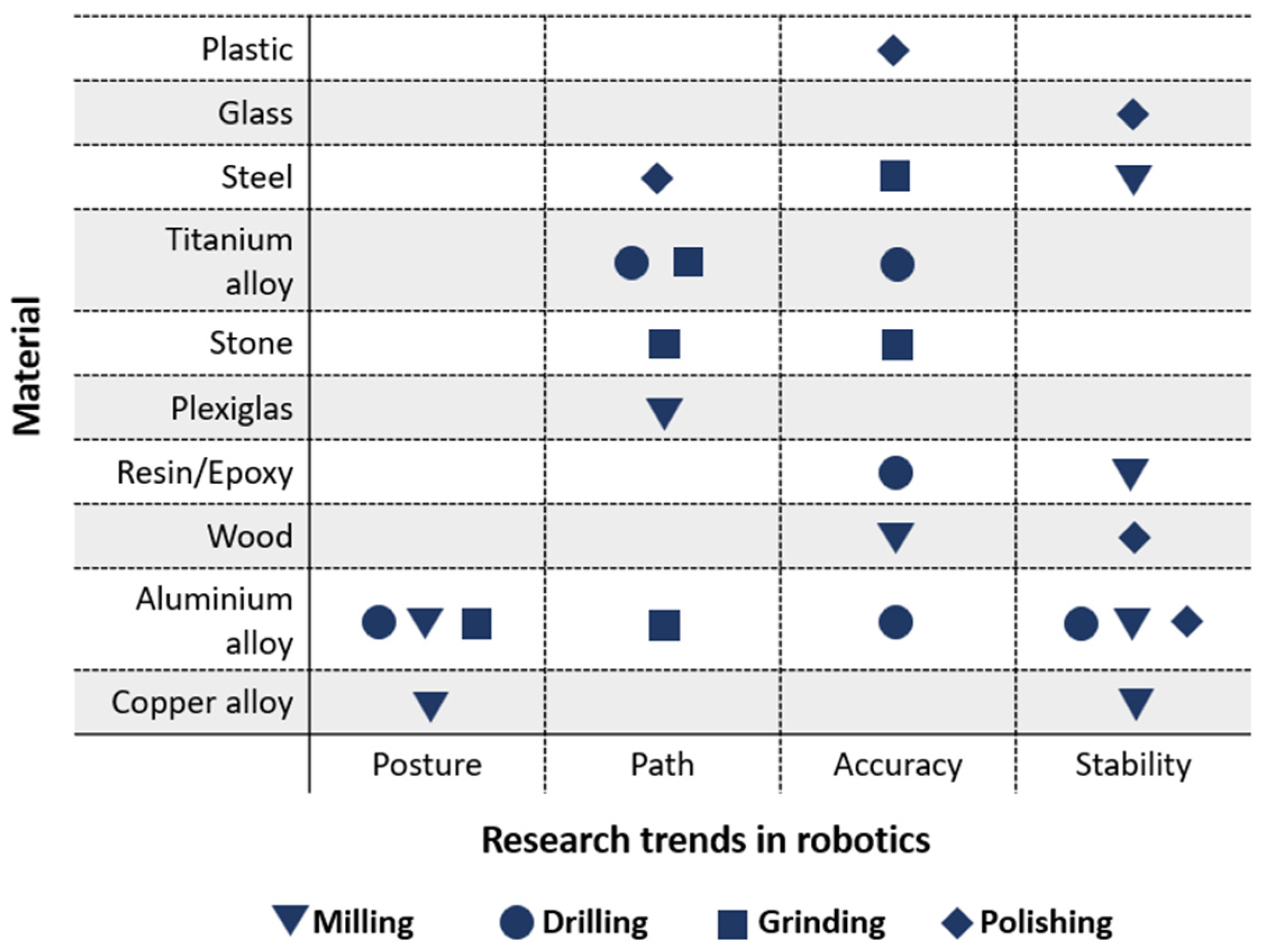
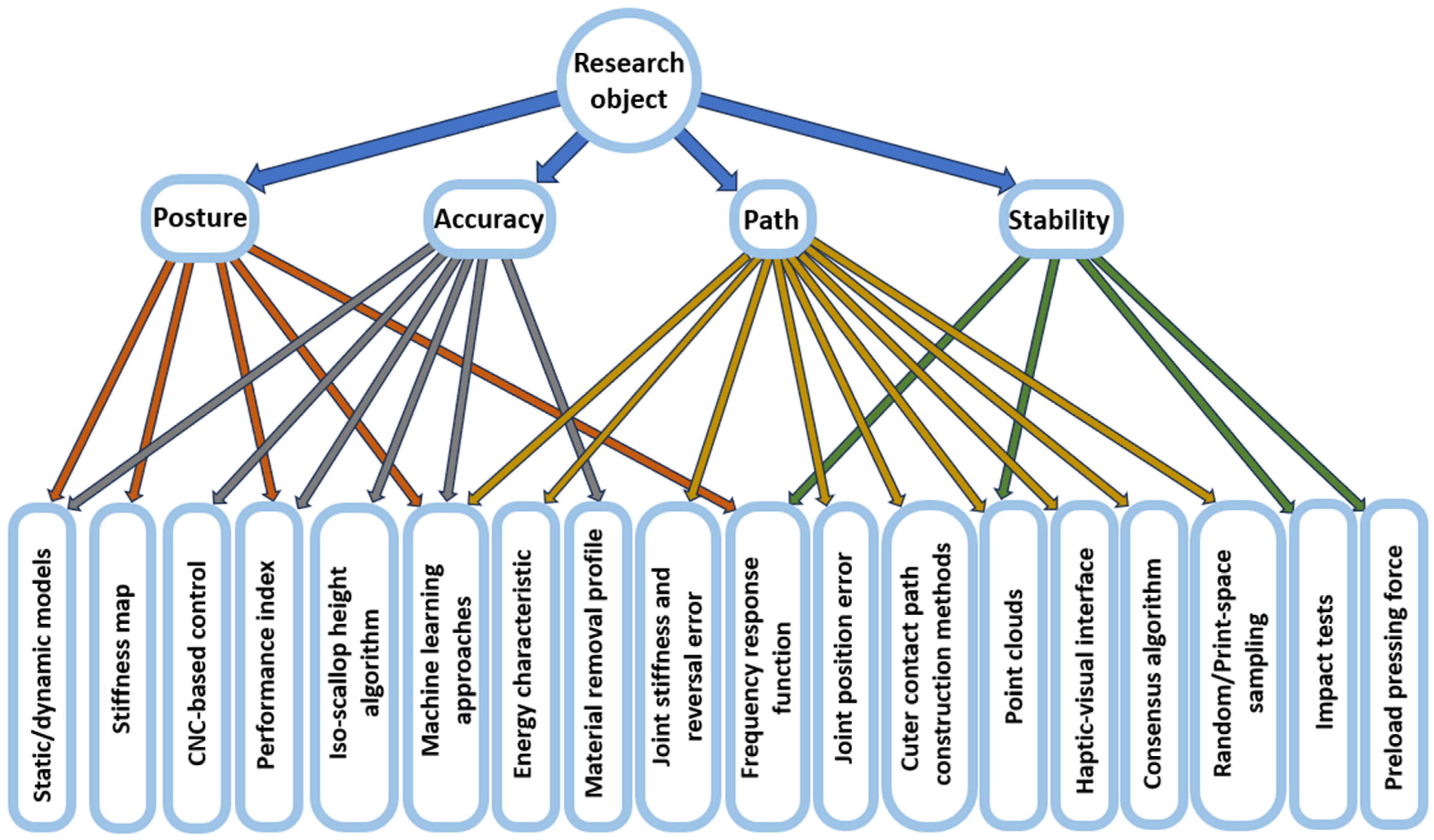
- Firstly, there is an evident distribution between the provided solutions and robotic quality parameters;
- Of the eighteen solutions classified, thirteen rely on only quality parameters, four are important to two parameters, and only one solution has high importance to three parameters;
- The presence of three quality parameters in the ML approach highlights the importance of bringing new perspectives to future solutions in robotics.
Author Contributions
Funding
Data Availability Statement
Conflicts of Interest
References
- Lv, Y.; Peng, Z.; Qu, C.; Zhu, D. An Adaptive Trajectory Planning Algorithm for Robotic Belt Grinding of Blade Leading and Trailing Edges Based on Material Removal Profile Model. Robot. Comput. Integr. Manuf. 2020, 66, 101987. [Google Scholar] [CrossRef]
- Lu, L.; Zhang, J.; Fuh, J.Y.H.; Han, J.; Wang, H. Time-Optimal Tool Motion Planning with Tool-Tip Kinematic Constraints for Robotic Machining of Sculptured Surfaces. Robot. Comput. Integr. Manuf. 2020, 65, 101969. [Google Scholar] [CrossRef]
- Haage, M.; Profanter, S.; Kessler, I.; Somani, N.; Karlsson, M.; Robertz, S.G.; Marti, M. On Cognitive Robot Woodworking in SMErobotics. In Proceedings of the ISR 2016: 47st International Symposium on Robotics, Munich, Germany, 21–22 June 2016; VDE: Munich, Germany, 2016. [Google Scholar]
- Quintero, C.P.; Li, S.; Pan, M.K.; Chan, W.P.; Machiel Van Der Loos, H.F.; Croft, E. Robot Programming Through Augmented Trajectories in Augmented Reality. In Proceedings of the 2018 IEEE/RSJ International Conference on Intelligent Robots and Systems (IROS), Madrid, Spain, 1–5 October 2018; pp. 1838–1844. [Google Scholar] [CrossRef]
- Kubela, T.; Pochyly, A.; Singule, V. Assessment of Industrial Robots Accuracy in Relation to Accuracy Improvement in Machining Processes. In Proceedings of the 2016 IEEE International Power Electronics and Motion Control Conference (PEMC), Varna, Bulgaria, 25–28 September 2016; pp. 720–725. [Google Scholar] [CrossRef]
- Schneider, U.; Drust, M.; Ansaloni, M.; Lehmann, C.; Pellicciari, M.; Leali, F.; Gunnink, J.W.; Verl, A. Improving Robotic Machining Accuracy through Experimental Error Investigation and Modular Compensation. Int. J. Adv. Manuf. Technol. 2016, 85, 3–15. [Google Scholar] [CrossRef]
- Ji, W.; Wang, L. Industrial Robotic Machining: A Review. Int. J. Adv. Manuf. Technol. 2019, 103, 1239–1255. [Google Scholar] [CrossRef]
- Hyeon Kim, S.; Nam, E.; In Ha, T.; Hwang, S.-H.; Ho Lee, J.; Park, S.-H.; Min, B.-K. Robotic Machining: A Review of Recent Progress. Int. J. Precis. Eng. Manuf. 2019, 20, 1629–1642. [Google Scholar] [CrossRef]
- Iglesias, I.; Sebastián, M.A.; Ares, J.E. Overview of the State of Robotic Machining: Current Situation and Future Potential. Procedia Eng. 2015, 132, 911–917. [Google Scholar] [CrossRef]
- Verl, A.; Valente, A.; Melkote, S.; Brecher, C.; Ozturk, E.; Tunc, L.T. Robots in Machining. CIRP Ann. 2019, 68, 799–822. [Google Scholar] [CrossRef]
- Cvitanic, T.; Nguyen, V.; Melkote, S.N. Pose Optimization in Robotic Machining Using Static and Dynamic Stiffness Models. Robot. Comput. Integr. Manuf. 2020, 66, 101992. [Google Scholar] [CrossRef]
- Kaldestad, K.B.; Tyapin, I.; Hovland, G. Robotic Face Milling Path Correction and Vibration Reduction. In Proceedings of the IEEE International Conference on Advanced Intelligent Mechatronics (AIM), Busan, Korea, 7–11 July 2015; pp. 543–548. [Google Scholar] [CrossRef]
- Karim, A.; Hitzer, J.; Lechler, A.; Verl, A. Analysis of the Dynamic Behavior of a Six-Axis Industrial Robot within the Entire Workspace in Respect of Machining Tasks. In Proceedings of the 2015 IEEE International Conference on Advanced Intelligent Mechatronics (AIM), Busan, Republic of Korea, 7–11 July 2017; pp. 670–675. [Google Scholar] [CrossRef]
- Sun, Y.; Shi, Z.; Guo, Q.; Xu, J. A Novel Method to Predict Surface Topography in Robotic Milling of Directional Plexiglas Considering Cutter Dynamical Displacement. J. Mater. Process. Technol. 2022, 304, 117545. [Google Scholar] [CrossRef]
- Pérez-Ruiz, J.D.; de Lacalle, L.N.L.; Urbikain, G.; Pereira, O.; Martínez, S.; Bris, J. On the Relationship between Cutting Forces and Anisotropy Features in the Milling of LPBF Inconel 718 for near Net Shape Parts. Int. J. Mach. Tools Manuf. 2021, 170, 103801. [Google Scholar] [CrossRef]
- Gonzalez, M.K.; Theissen, N.A.; Barrios, A.; Archenti, A. Online Compliance Error Compensation System for Industrial Manipulators in Contact Applications. Robot. Comput. Integr. Manuf. 2022, 76, 102305. [Google Scholar] [CrossRef]
- Chen, C.; Peng, F.; Yan, R.; Fan, Z.; Li, Y.; Wei, D. Posture-Dependent Stability Prediction of a Milling Industrial Robot Based on Inverse Distance Weighted Method. Procedia Manuf. 2018, 17, 993–1000. [Google Scholar] [CrossRef]
- Nguyen, V.; Johnson, J.; Melkote, S. Active Vibration Suppression in Robotic Milling Using Optimal Control. Int. J. Mach. Tools Manuf. 2020, 152, 103541. [Google Scholar] [CrossRef]
- Chen, C.; Peng, F.; Yan, R.; Li, Y.; Wei, D.; Fan, Z.; Tang, X.; Zhu, Z. Stiffness Performance Index Based Posture and Feed Orientation Optimization in Robotic Milling Process. Robot. Comput. Integr. Manuf. 2019, 55, 29–40. [Google Scholar] [CrossRef]
- Xiong, G.; Ding, Y.; Zhu, L.M. Stiffness-Based Pose Optimization of an Industrial Robot for Five-Axis Milling. Robot. Comput. Integr. Manuf. 2019, 55, 19–28. [Google Scholar] [CrossRef]
- Wang, Z.Q.; Liu, X.Q.; Wang, X.R.; Li, C.Y.; Yang, N.; Lin, T.S. Robotic Milling of Complex NURBS Surface with Fixed Cutter Axis Control Method. Ind. Robot. 2021, 48. [Google Scholar] [CrossRef]
- Zhu, D.; Feng, X.; Xu, X.; Yang, Z.; Li, W.; Yan, S.; Ding, H. Robotic Grinding of Complex Components: A Step towards Efficient and Intelligent Machining—Challenges, Solutions, and Applications. Robot. Comput. Integr. Manuf. 2020, 65, 101908. [Google Scholar] [CrossRef]
- Yin, F.; Wu, S.; Huang, H.; Cui, C.; Ji, Q. Effect of Machining Trajectory on Grinding Force of Complex-Shaped Stone by Robotic Manipulator. Machines 2022, 10, 787. [Google Scholar] [CrossRef]
- Xie, H.; Li, W.L.; Zhu, D.H.; Yin, Z.P.; Ding, H. A Systematic Model of Machining Error Reduction in Robotic Grinding. IEEE/ASME Trans. Mechatron. 2020, 25, 2961–2972. [Google Scholar] [CrossRef]
- Zhou, P.; Zhao, X.; Tao, B.; Ding, H. Time-Varying Isobaric Surface Reconstruction and Path Planning for Robotic Grinding of Weak-Stiffness Workpieces. Robot. Comput. Integr. Manuf. 2020, 64, 101945. [Google Scholar] [CrossRef]
- Wan, G.; Wang, G.; Fan, Y. A Robotic Grinding Station Based on an Industrial Manipulator and Vision System. PLoS ONE 2021, 16, e0248993. [Google Scholar] [CrossRef]
- Xie, Y.; Chang, G.; Yang, J.; Zhao, M.; Li, J. Process Optimization of Robotic Polishing for Mold Steel Based on Response Surface Method. Materials 2022, 10, 283. [Google Scholar] [CrossRef]
- Liang, X.; Cai, Z.; Zeng, C.; Mu, Z.; Li, Z.; Yang, F.; Chen, T.; Dong, S.; Deng, C.; Niu, S. A Robotic Polishing Trajectory Planning Method for TBCs of Aero-Engine Turbine Blade Using Measured Point Cloud. Ind. Robot. 2023, 50, 275–286. [Google Scholar] [CrossRef]
- Zhu, R.; Yang, G.; Fang, Z.; Dai, J.; Chen, C.Y.; Zhang, G.; Zhang, C. Hybrid Orientation/Force Control for Robotic Polishing with a 2R1T Force-Controlled End-Effector. Int. J. Adv. Manuf. Technol. 2022, 121, 2279–2290. [Google Scholar] [CrossRef]
- Wahballa, H.; Duan, J.; Dai, Z. Constant Force Tracking Using Online Stiffness and Reverse Damping Force of Variable Impedance Controller for Robotic Polishing. Int. J. Adv. Manuf. Technol. 2022, 121, 5855–5872. [Google Scholar] [CrossRef]
- Zhang, J.; Zhao, L.; Li, L.; Ma, F.; Chen, G. Design of Passive Constant-Force End-Effector for Robotic Polishing of Optical Reflective Mirrors. Chin. J. Mech. Eng. 2022, 35, 141. [Google Scholar] [CrossRef]
- Wei, Y.; Xu, Q. Design of a New Passive End-Effector Based on Constant-Force Mechanism for Robotic Polishing. Robot. Comput. Integr. Manuf. 2022, 74, 102278. [Google Scholar] [CrossRef]
- Tian, F.; Li, Z.; Lv, C.; Liu, G. Polishing Pressure Investigations of Robot Automatic Polishing on Curved Surfaces. Int. J. Adv. Manuf. Technol. 2016, 87, 639–646. [Google Scholar] [CrossRef]
- Wang, Z.; Zhang, R.; Keogh, P. Real-Time Laser Tracker Compensation of Robotic Drilling and Machining. J. Manuf. Mater. Process. 2020, 4, 79. [Google Scholar] [CrossRef]
- Lu, H.; Zhao, X.; Tao, B.; Ding, H. A State-Classification Approach for Light-Weight Robotic Drilling Using Model-Based Data Augmentation and Multi-Level Deep Learning. Mech. Syst. Signal Process. 2022, 167, 108480. [Google Scholar] [CrossRef]
- Zhang, J.; Liao, W.; Bu, Y.; Tian, W.; Hu, J. Stiffness Properties Analysis and Enhancement in Robotic Drilling Application. Int. J. Adv. Manuf. Technol. 2020, 106, 5539–5558. [Google Scholar] [CrossRef]
- Arthur, J.; Khoshdarregi, M. Pose Optimization and Path Improvement in Robotic Drilling through Minimization of Joint Reversals. Adv. Robot. 2022, 2022, 1076–1086. [Google Scholar] [CrossRef]
- Pereira, B.; Griffiths, C.A.; Birch, B.; Rees, A. Optimization of an Autonomous Robotic Drilling System for the Machining of Aluminum Aerospace Alloys. Int. J. Adv. Manuf. Technol. 2022, 119, 2429–2444. [Google Scholar] [CrossRef]
- Farhadi, A.; Lee, S.K.H.; Hinchy, E.P.; O’dowd, N.P.; Avizzano, C.A.; Farhadi, A.; Lee, S.K.H.; Hinchy, E.P.; O’dowd, N.P.; Mccarthy, C.T. The Development of a Digital Twin Framework for an Industrial Robotic Drilling Process. Sensors 2022, 22, 7232. [Google Scholar] [CrossRef]
- Onstein, I.F.; Semeniuta, O.; Bjerkeng, M. Deburring Using Robot Manipulators: A Review. In Proceedings of the 2020 3rd International Symposium on Small-Scale Intelligent Manufacturing Systems (SIMS 2020), Gjøvik, Norway, 10–12 June 2020. [Google Scholar] [CrossRef]
- Gonzalez, M.; Rodriguez, A.; Pereira, O.; Celaya, A.; Lopez de Lacalle, L.N.; Esparta, M. Axial-Compliant Tools for Adaptive Chamfering of Sharp-Edges: Characterisation and Modelling. Eng. Sci. Technol. Int. J. 2023, 41, 101407. [Google Scholar] [CrossRef]
- Hu, J.; Pagilla, P.R. A Novel Force and Motion Control Strategy for Robotic Chamfering of Gears. IFAC-PapersOnLine 2020, 53, 8710–8715. [Google Scholar] [CrossRef]
- Miller, G.; Irani, R.A.; Ahmadi, M. The Application of Mechanistic Cutting Force Models for Robotic Deburring. Int. J. Adv. Manuf. Technol. 2021, 115, 199–212. [Google Scholar] [CrossRef]
- Wang, G.; Dong, H.; Guo, Y.; Ke, Y. Early Chatter Identification of Robotic Boring Process Using Measured Force of Dynamometer. Int. J. Adv. Manuf. Technol. 2018, 94, 1243–1252. [Google Scholar] [CrossRef]
- Lin, Y.; Zhao, H.; Ding, H. Real-Time Path Correction of Industrial Robots in Machining of Large-Scale Components Based on Model and Data Hybrid Drive. Robot. Comput. Integr. Manuf. 2023, 79, 102447. [Google Scholar] [CrossRef]
- Cordes, M.; Hintze, W. Offline Simulation of Path Deviation Due to Joint Compliance and Hysteresis for Robot Machining. Int. J. Adv. Manuf. Technol. 2017, 90, 1075–1083. [Google Scholar] [CrossRef]
- Stepputat, M.; Beuss, F.; Pfletscher, U.; Sender, J.; Fluegge, W. Automated One-off Production in Woodworking by Part-to-Tool. Procedia CIRP 2021, 104, 307–312. [Google Scholar] [CrossRef]
- Zhou, J.; Cao, H.; Jiang, P.; Li, C.; Yi, H.; Liu, M. Energy-Saving Trajectory Planning for Robotic High-Speed Milling of Sculptured Surfaces. IEEE Trans. Autom. Sci. Eng. 2022, 19, 2278–2294. [Google Scholar] [CrossRef]
- Munasinghe, N.; Paul, G. Path Planning for Robot Based Radial Advanced Manufacturing Using Print Space Sampling. In Proceedings of the 16th IEEE International Conference on Control, Automation, Robotics and Vision (ICARCV), Shenzhen, China, 13–15 December 2020; pp. 854–859. [Google Scholar] [CrossRef]
- Wang, G.; Li, W.; Jiang, C.; Zhu, D.; Li, Z.; Xu, W.; Zhao, H.; Ding, H. Trajectory Planning and Optimization for Robotic Machining Based on Measured Point Cloud. IEEE Trans. Robot. 2022, 38, 1621–1637. [Google Scholar] [CrossRef]
- Sánchez, I.I.; Ares, J.E.; Gaya, C.G.; Prieto, V.R. A New Approach to the Consideration and Analysis of Critical Factors in Robotic Machining. Appl. Sci. 2020, 10, 8885. [Google Scholar] [CrossRef]
- Sun, Y.; Jia, J.; Xu, J.; Chen, M.; Niu, J. Path, Feedrate and Trajectory Planning for Free-Form Surface Machining: A State-of-the-Art Review. Chin. J. Aeronaut. 2022, 35, 12–29. [Google Scholar] [CrossRef]
- Morozov, M.; Pierce, S.G.; MacLeod, C.N.; Mineo, C.; Summan, R. Off-Line Scan Path Planning for Robotic NDT. Measurement 2018, 122, 284–290. [Google Scholar] [CrossRef]
- Pham, Q.C.; Stasse, O. Time-Optimal Path Parameterization for Redundantly Actuated Robots: A Numerical Integration Approach. IEEE/ASME Trans. Mechatron. 2015, 20, 3257–3263. [Google Scholar] [CrossRef]
- Lin, Y.; Zhao, H.; Ding, H. Posture Optimization Methodology of 6R Industrial Robots for Machining Using Performance Evaluation Indexes. Robot. Comput. Integr. Manuf. 2017, 48, 59–72. [Google Scholar] [CrossRef]
- Hu, J.; Li, C.; Chen, Z.; Yao, B. Precision Motion Control of a 6-DoFs Industrial Robot with Accurate Payload Estimation. IEEE/ASME Trans. Mechatron. 2020, 25, 1821–1829. [Google Scholar] [CrossRef]
- Wu, K.; Krewet, C.; Kuhlenkötter, B. Dynamic Performance of Industrial Robot in Corner Path with CNC Controller. Robot. Comput. Integr. Manuf. 2018, 54, 156–161. [Google Scholar] [CrossRef]
- Moeller, C.; Schmidt, H.C.; Koch, P.; Boehlmann, C.; Kothe, S.; Wollnack, J.; Hintze, W.; Moeller, C.; Schmidt, C.; Koch, H.; et al. Real Time Pose Control of an Industrial Robotic System for Machining of Large Scale Components in Aerospace Industry Using Laser Tracker System “Real Time Pose Control of an Industrial Robotic System for Machining of Large Scale Components in Aerospace Industry Using Laser Tracker System. SAE Int. J. Aerosp. 2017, 10, 100–108. [Google Scholar] [CrossRef]
- Yamaguchi, N.; Aiuchi, K.; Morita, N.; Miyashita, J.; Moriya, M.; Maeda, K.; Uchiyama, N. Calibration of Robotic Wood working Machinery Using a Motion Capture System. In Proceedings of the 2022 IEEE/SICE International Symposium on System Integration (SII), Narvik, Norway, 9–12 January 2022. [Google Scholar] [CrossRef]
- Janez, G.; Timi, K.; Karl, G.; Miran, B. Accuracy Improvement of Robotic Machining Based on Robot’s Structural Properties. Int. J. Adv. Manuf. Technol. 2020, 108, 1309–1329. [Google Scholar] [CrossRef]
- Hoai Nam, H.; Riviere, E.; Nam Huynh, H.; Ere-Lorphèvre, E.; Verlinden, O. Multibody Modelling of a Flexible 6-Axis Robot Dedicated to Robotic Machining. In Proceedings of the 5th Joint International Conference on Multibody System Dynamics (IMSD), Lisbon, Portugal, 24–28 June 2018. [Google Scholar]
- Mateo, C.M.; Gil, P.; Torres, F. Visual Perception for the 3D Recognition of Geometric Pieces in Robotic Manipulation. Int. J. Adv. Manuf. Technol. 2016, 83, 1999–2013. [Google Scholar] [CrossRef]
- Gharaaty, S.; Shu, T.; Joubair, A.; Xie, W.F.; Bonev, I.A. Online Pose Correction of an Industrial Robot Using an Optical Coordinate Measure Machine System. Sage J. 2018, 15, 1–16. [Google Scholar] [CrossRef]
- Xue, K.; Wang, Z.; Shen, J.; Hu, S.; Zhen, Y.; Liu, J.; Wu, D.; Yang, H. Robotic Seam Tracking System Based on Vision Sensing and Human-Machine Interaction for Multi-Pass MAG Welding. J. Manuf. Process. 2021, 63, 48–59. [Google Scholar] [CrossRef]
- Bilal, D.K.; Unel, M.; Tunc, L.T.; Gonul, B. Development of a Vision Based Pose Estimation System for Robotic Machining and Improving Its Accuracy Using LSTM Neural Networks and Sparse Regression. Robot. Comput. Integr. Manuf. 2022, 74, 102262. [Google Scholar] [CrossRef]
- Bucinskas, V.; Dzedzickis, A.; Sumanas, M.; Sutinys, E.; Petkevicius, S.; Butkiene, J.; Virzonis, D.; Morkvenaite-Vilkonciene, I. Improving Industrial Robot Positioning Accuracy to the Microscale Using Machine Learning Method. Machines 2022, 10, 940. [Google Scholar] [CrossRef]
- Yin, S.; Ji, W.; Wang, L. A Machine Learning Based Energy Efficient Trajectory Planning Approach for Industrial Robots. Procedia CIRP 2019, 81, 429–434. [Google Scholar] [CrossRef]
- Zhang, D.; Zhang, N.; Ye, N.; Fang, J.; Han, X. Hybrid Learning Algorithm of Radial Basis Function Networks for Reliability Analysis. IEEE Trans. Reliab. 2021, 70, 887–900. [Google Scholar] [CrossRef]
- Pandiyan, V.; Murugan, P.; Tjahjowidodo, T.; Caesarendra, W.; Manyar, O.M.; Then, D.J.H. In-Process Virtual Verification of Weld Seam Removal in Robotic Abrasive Belt Grinding Process Using Deep Learning. Robot. Comput. Integr. Manuf. 2019, 57, 477–487. [Google Scholar] [CrossRef]


| Problem | Methods | Industrial Robot | Additional Means | Ref. |
|---|---|---|---|---|
| Poor grinding accuracy and surface quality | Review on calibration and measurement, trajectory planning, force control, and surface integrity | - | Active/passive force control sensors, PID-based control | [22] |
| Examination of curvature characteristics of complex-shaped stone products | The matching relationship between surface characteristics and machining trajectory | KUKA QUANTECK KR240 R2900 ultra | Kistler’s 9170B 6-dimensional torque sensor. | [23] |
| Free-form surface machining is limited by individual kinematic errors or joint stiffness. | Speed and force adjoint transformation, fine-tuning the workpiece frame position | ABB industrial robot with RobotStudio 2020.3 software | Grinding machine with a belt, robot here is a workpiece manipulator | [24] |
| Profile accuracy enhancement | Trajectory planning algorithm adapting the material removal profile (MRP) | - | Trajectory planning software based on OpenCASCADE | [1] |
| Grinding of weak-stiffness workpieces | Deformation and stiffness measurements and time-varying isobaric surface (TVIS) mesh generation | Universal Robot UR5 | Six-dimensional force sensor ATI Axia80 | [25] |
| Increasing demands for precision and automation | Geometric-multilevel-Line-2D method | EFORT ER50-C10, ABB IRB6700 | Different shape parts, vision system, PC workstation (CPU: i7, GPU: RTX 2070S, RAM: 32G) | [26] |
| Problem | Methods | Industrial Robot | Additional Means | Ref. |
|---|---|---|---|---|
| Surface roughness reduction and improvement of surface quality of mold steel | Optimizations of process parameters: polishing pressure, feed speed, and rotating speed of the tool | KUKA KR60-3 | Force control with a six-dimensional force sensor | [27] |
| Surface roughness reduction of blades | Point cloud preprocessing, slicing algorithm, and the intersection method | ABB IRB 1200–7/0.7 with RobotStudio simulations | 3D profile sensor | [28] |
| Achievement of consistent surface quality | Contact point compensation model to predict the contact point variation | ABB industrial robot | Force-controlled end-effector | [29] |
| Desire constant force tracking control | Impedance controller with online stiffness and reverse damping force | 7-DOF X-mate3- Pro | Lyapunov function, force sensor | [30] |
| Maintenance of a constant force between the robot and the workpiece | Constant force compliant mechanism, compared to traditional methods using force control | 7-DOF KUKA industrial robot | Passive constant force end-effector, K9 R467 reflective mirror | [31] |
| Achievement of constant polishing pressure | Preston equation and Hertz theory-based constant force mechanism | Universal Robot UR5 | Constant force end-effector | [32] |
| Improvement of finishing efficiency, surface quality, and surface consistency | A relation model between removal rate and polishing pressure | Kuka KR30-3 | Force/torque sensor | [33] |
| Problem | Methods | Industrial Robot | Additional Means | Ref. |
|---|---|---|---|---|
| Low structural stiffness and low positional accuracy | Ballbar dynamic path accuracy, a series of drilling case studies, and machining tests | KUKA KR120R2500 PRO with a KUKA KR C4 controller | Single 3-DOF laser tracker | [34] |
| Detection of unqualified holes caused by inclined drilling | Vibration-based classification | UR industrial robot | Resnet classifier with vibration model, camera | [35] |
| Robot stiffness influence on drilling quality | Preload pressing force to strengthen the stiffness of the machining plane | KUKA industrial robot | ZEISS SPECTRUM II Coordinate measuring machine | [36] |
| Static friction in robot joints impacts the quality | Optimization framework, which models a general drilling motion minimizing joint reversals | KUKA KR 6 R700-2 | Particle Swarm Optimization | [37] |
| Hole surface roughness and exit burr heights | Taguchi design methodology | Kuka KR16 | CNC milling machine as a reference, SignalCalc Ace Vibration sensors | [38] |
| A unified digital twin framework for the manufacturing environment is missing. | Generic reference model to highlight elements of the digital twin | KUKA KR210 R3100 Ultra with a KRC4 controller | Based on ISO 23247 standard, the drilling and vision module | [39] |
| Problem | Methods | Industrial Robot | Additional Means | Ref. |
|---|---|---|---|---|
| Poor positioning accuracy | Force control | ABB IRB-4600 | Cone-shape stone tool, Omega 85 force-torque sensor, AFD 310 compliant device, spindle, robot operating system (ROS) | [42] |
| The need for suitable force prediction | Linear regression method, exponential model based on the simplex search method | Unspecified six-DOF robot | Force-torque sensor, laser scanner, spindle, aluminum 6061 workpiece | [43] |
| Poor quality and efficiency of the hole | Prediction based on measured force, intrinsic mode functions, empirical mode decomposition, Hilbert transform, and spectrum | ABB-IRB6600 | Kistler9257B dynamometer, end-effector, mobile platform, control system | [44] |
| Problem | Methods | Industrial Robot | Additional Means | Ref. |
|---|---|---|---|---|
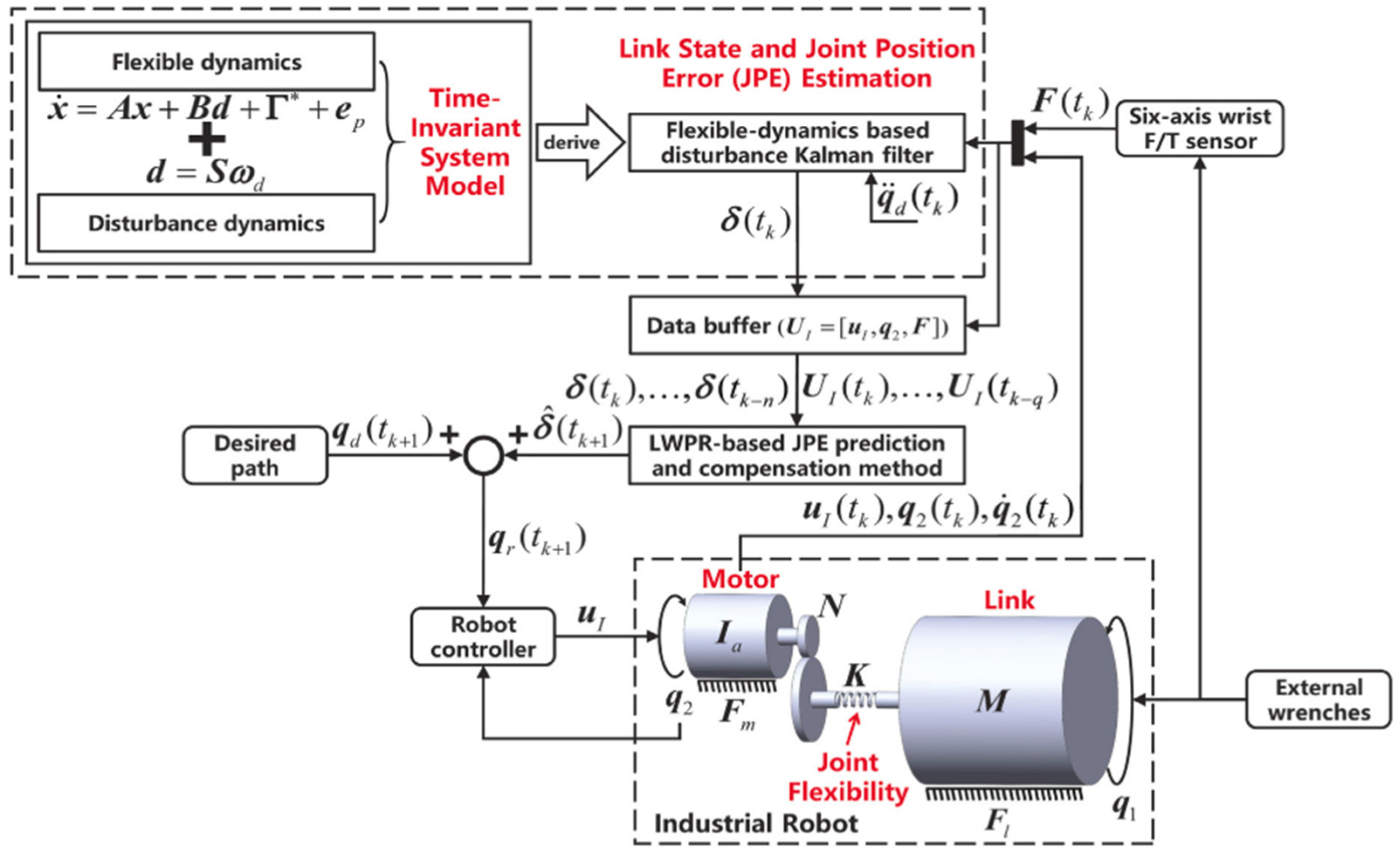
| Insufficient manipulator stiffness | Real-time path correction applying joint position error (JPE) | ODG-JLRB20 | flexible-dynamics-based disturbance Kalman filter (FDBDKF), force/torque sensor, MATLAB | [45] |
| Path deviation prediction | Based on joint stiffness and reversal error | ABB IRB 6660-205/1.9 | Laser tracker, dynamometer, reflector | [46] |
| Insufficient manipulator stiffness | Automatically Programmed-Tool (APT) code to generate Part-to-Tool (PtT) path | Not specified six-DOF industrial robot | - | [47] |
| Severe deformations and vibration | Deformation and stiffness measurements, and TVIS mesh generation | Universal Robot UR5 | Six-dimensional force sensor ATI Axia80 | [25] |
| The influence of the trajectory planning method resulting poor accuracy of blade edges | Iso-scallop height algorithm, material removal profile | - | A 6-axis force/torque sensor, trajectory planning software based on OpenCASCADE | [1] |
| Minimization of energy | Energy characteristic to acquire the energy-optimal feed rate | KUKA KR60-3 | Computer (Intel i3-8100 CPU 3.60 GHz and 8-GB DDR2) | [48] |
| Distance error optimization and manipulability | Cost-based path planning to adapt print-space sampling | ABB IRB 120 | MATLAB robotics toolbox | [49] |
| Machining of large and complex parts | Energy-based trajectory smoothness optimization method based on the point clouds | ABB IRB 6660-205/1.9 | Laser tracker, T-scan 3D scanner | [50] |
| Identification of critical factors affecting the machining path | Predictive methodology | ABB IRB 6660-205/1.9 | MITUTOYO coordinate measuring machine | [51] |
| Tool path generation, feed rate scheduling, and trajectory planning | Cuter contact path construction methods | ABB industrial robot | The 3/5-axis CNC machine tools (for reference), laser sensor, rotary dynamometer | [52] |
| Curved tool path complexity and time-optimal motion planning | Pontryagin maximum principle | Elfin 5 with ROS | Moveit library | [2] |
| Computer-aided scan path generation | Swept frequency eddy currents method | KUKA KR5 with MasterCAM X6 | Laser tracker | [53] |
| Problem | Methods | Industrial Robot | Additional Means | Ref. |
|---|---|---|---|---|
| Minimization of end-effector displacement | Static/dynamic model-based pose selection | KUKA KR 500–3 | Six-DOF laser tracker, six-axis force/torque sensor | [11] |
| Prediction of the industrial robot stability at any posture | FRF at the tool tip | ABB IRB 6660-205 | Sound microphone, NI data acquisition system | [17] |
| Analyzation of the stiffness properties | Task-dependent PI | ABB IRB 6660-205 | NI data acquisition system, laser tracker, dynamometer | [19] |
| Posture optimization | Based on robotic PIs and stiffness map | Comau Smart5 NJ 220-2.7 | Laser tracker and retroreflector | [55] |
| Problem | Control Methods | Industrial Robot | Additional Means | Ref. |
|---|---|---|---|---|
| Simplification of the excitation trajectory optimization | DIARC algorithm | COMAU-RACER3 | MATLAB, Automation studio IDE, encoders | [56] |
| Improvement of the machining accuracy | Use of a CNC controller as the control system | KUKA KR 210 R2700 | High-speed camera, KR C4 controller | [57] |
| Trajectory interaction and ease the robot programming | Augmented reality (AR) robotic control system | Barrett Whole-Arm 7-DOF Manipulator | Head-mounted display (Microsoft Hololens), MYO armband | [4] |
| Problem | Sensors | Industrial Robot | Additional Means | Ref. |
|---|---|---|---|---|
| Poor absolute accuracy | Laser tracker system | MABI Robotic Max 150 | Siemens Sinumerik 840D sl-CNC controller, reflectors | [58] |
| Expensive calibration | Motion capture system | FANUC industrial robot | MATLAB Optimization Toolbox, ROBOGUIDE Simulator | [59] |
| Poor milling accuracy | Body mounted accelerometer | ACMA XR701 | Impact hammer tests and FEM model calibration | [60] |
| The effects assessment of gravity, joint flexibility, and bending | Force sensor | Stabil TX200 | The use of torsional springs and dampers | [61] |
| Obtain the positions of objects during grasping and robotic manipulation | Visual recognition system | Mitsubishi PA-10 7-DOF | Client-server architecture and communication via ARCNET | [62] |
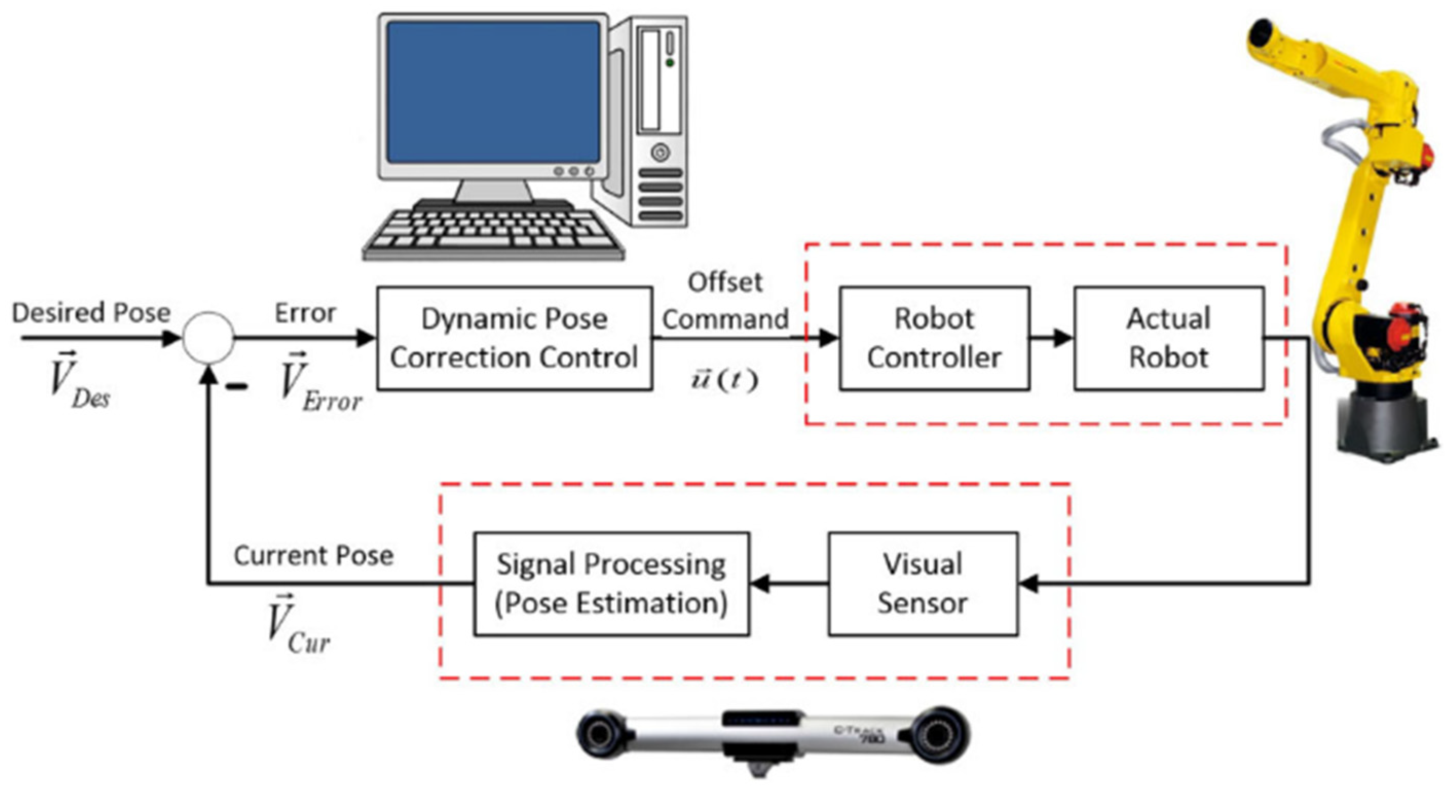
| Poor pose accuracy | Optical coordinate measuring machine | FANUC LR Mate 200iC and FANUC M20iA | Root mean square method, dynamic pose correction algorithm | [63] |
| Control of the deviations and correction | Vision sensing (CCD and Laser) | KUKA KR 16 L8 with KUKA robot controller (KRC) | Human-machine interaction module, programmable logic controller | [64] |
| Application | ML Models | Industrial Robot | Additional Means | Ref. |
|---|---|---|---|---|
| 3D object recognition | Neural Network (NN) | Mitsubishi PA-10 | Microsoft Kinect™ RGBD range sensor | [62] |
| Monocular machine vision-based pose estimation | Long Short-Term Memory (LSTM) NN | KUKA KR240 R2900 | Extended Kalman Filter (EKF) (for comparison) | [65] |
| Analyzation of experimentally predetermined robot properties and their impact on overall accuracy | Deep Q-learning-based approach | KUKA-YouBot | Two USB cameras, accelerometers, data acquisition system USB-4432, MATLAB | [66] |
| Energy-efficient trajectory planning | Deep learning network, evolutional-based or swarm-intelligence-based algorithms | Not specified six-DOF industrial robot | MATLAB | [67] |
| Positioning accuracy reliability analysis | Hybrid learning algorithm (HLA) for training a radial basis function network | Not specified six-DOF industrial robot | Monte Carlo simulation method (for comparison), MATLAB | [68] |
| Weld seam removal with robotic grinding process | Convolutional neural network (CNN) architecture | ABB 6660-205-19 | Camera system with resolution of 1240 × 960 pixels, MATLAB | [69] |
Disclaimer/Publisher’s Note: The statements, opinions and data contained in all publications are solely those of the individual author(s) and contributor(s) and not of MDPI and/or the editor(s). MDPI and/or the editor(s) disclaim responsibility for any injury to people or property resulting from any ideas, methods, instructions or products referred to in the content. |
© 2023 by the authors. Licensee MDPI, Basel, Switzerland. This article is an open access article distributed under the terms and conditions of the Creative Commons Attribution (CC BY) license (https://creativecommons.org/licenses/by/4.0/).
Share and Cite
Makulavičius, M.; Petkevičius, S.; Rožėnė, J.; Dzedzickis, A.; Bučinskas, V. Industrial Robots in Mechanical Machining: Perspectives and Limitations. Robotics 2023, 12, 160. https://doi.org/10.3390/robotics12060160
Makulavičius M, Petkevičius S, Rožėnė J, Dzedzickis A, Bučinskas V. Industrial Robots in Mechanical Machining: Perspectives and Limitations. Robotics. 2023; 12(6):160. https://doi.org/10.3390/robotics12060160
Chicago/Turabian StyleMakulavičius, Mantas, Sigitas Petkevičius, Justė Rožėnė, Andrius Dzedzickis, and Vytautas Bučinskas. 2023. "Industrial Robots in Mechanical Machining: Perspectives and Limitations" Robotics 12, no. 6: 160. https://doi.org/10.3390/robotics12060160