Article

An Autonomous Navigation Framework for Holonomic Mobile Robots in Confined Agricultural Environments

by
Kosmas Tsiakas
1,2,†,
Alexios Papadimitriou
1,†,
Eleftheria Maria Pechlivani
1,*,
Dimitrios Giakoumis
1,
Nikolaos Frangakis
3,
Antonios Gasteratos
2 and
Dimitrios Tzovaras
1
1
Information Technologies Institute, Centre for Research and Technology Hellas, 57001 Thessaloniki, Greece
2
Department of Production and Management Engineering, Democritus University of Thrace, 67132 Xanthi, Greece
3
iKnowHow S.A., 15451 Athens, Greece
*
Author to whom correspondence should be addressed.
These authors contributed equally to this work.
Robotics 2023, 12(6), 146; https://doi.org/10.3390/robotics12060146
Submission received: 6 October 2023 / Revised: 25 October 2023 / Accepted: 26 October 2023 / Published: 28 October 2023
(This article belongs to the Special Issue Collection in Honor of Women's Contribution in Robotics)

Abstract

:
Due to the accelerated growth of the world’s population, food security and sustainable agricultural practices have become essential. The incorporation of Artificial Intelligence (AI)-enabled robotic systems in cultivation, especially in greenhouse environments, represents a promising solution, where the utilization of the confined infrastructure improves the efficacy and accuracy of numerous agricultural duties. In this paper, we present a comprehensive autonomous navigation architecture for holonomic mobile robots in greenhouses. Our approach utilizes the heating system rails to navigate through the crop rows using a single stereo camera for perception and a LiDAR sensor for accurate distance measurements. A finite state machine orchestrates the sequence of required actions, enabling fully automated task execution, while semantic segmentation provides essential cognition to the robot. Our approach has been evaluated in a real-world greenhouse using a custom-made robotic platform, showing its overall efficacy for automated inspection tasks in greenhouses.

1. Introduction

With the rapid expansion of the global population, the imperative to address the issues of food security and sustainable farming techniques has gained significant urgency. To meet the growing demand for food production, the agricultural sector has been driven to the excessive use of pesticides and herbicides [1], resulting in a significant impact on the environment and the surrounding ecosystem [2]. Consequently, it is imperative to employ alternative approaches to pest control by embracing innovative technologies and procedures that enhance effectiveness while minimizing negative ecological impacts. In the present context, the integration of robotics into the agricultural industry has emerged as a highly promising and transformational option, leading to significant changes in traditional farming methods. Additionally, current threats to agriculture, such as climate change and invasive pests, need to be urgently solved and AI-enabled robotic systems can significantly contribute to that, even though there are still numerous challenges and limitations to be solved [3].
The utilization of greenhouses, which include regulated settings, has historically been crucial in the optimization of agricultural development and the efficient management of resources. They provide a controlled environment that protects crops from the unpredictable fluctuations of the external climate and facilitates optimal conditions for crop growth, leading to extended growing seasons, increased yields, and reduced potential hazards associated with extreme climate-related occurrences, such as storms, frost, and excessive heat [4]. Moreover, greenhouses contribute to the establishment of a more secure and conducive working environment for agricultural workers [5]. Through the use of strategies such as limiting exposure to outdoor elements and employing controlled pest management techniques, the potential health hazards linked to chronic chemical exposure are mitigated. Nevertheless, the effective administration of greenhouses has its own array of difficulties. The conventional approaches frequently prove inadequate in attaining accurate management of variables such as temperature, humidity, and irrigation, resulting in unsatisfactory crop production and inefficient use of resources [6]. The implementation of autonomous navigation for robotic platforms in greenhouses promises a paradigm shift in tackling these difficulties, heralding a novel era of intelligent and environmentally-friendly agriculture.
In recent times, the agricultural sector has experienced a significant transformation due to the integration of robotics technology. This advancement has facilitated the automation of labor-intensive and repetitive activities, such as spraying, resulting in reduced labor expenses and enhanced operational effectiveness [7]. According to Fountas et al. [8], wheeled mobile robots possess notable attributes such as swift locomotion, extensive operational independence, and substantial load-carrying capacity. Additionally, these robots demonstrate the capability to navigate through challenging topographies and the implementation of omnidirectional kinematics enhances the versatility of wheeled robots, enabling them to effectively perform multiple tasks, including spot spraying.
Greenhouse environments are well adapted for automation using mobile robots since they are structured and are not frequently modified. Typically, plant benches are arranged in long, parallel aisles. These benches are interspersed with corridors, which typically contain a pair of long pipelines for controlling the temperature. Intriguingly, these pipes also serve as rails for diverse varieties of plant treatment equipment and serve as an ideal guide for the robot’s course, assuming it can utilize them effectively [9]. In addition, the greenhouse’s headland, which is the area outside of the corridors, is typically covered with a durable flat concrete floor.
By leveraging the existing infrastructure within greenhouses, mobile robots can navigate along these rails, enhancing their efficiency and precision during various tasks. This utilization of the greenhouse layout not only provides a well-defined path for the robot but also ensures that it can operate seamlessly alongside the existing infrastructure. The successful autonomous navigation of a mobile platform relies heavily on factors such as localization and mapping accuracy, path planning, and motion control. In the case of greenhouses, their semi-indoor nature poses limitations on the effectiveness of conventional approaches used in outdoor scenarios, such as those based on the Global Navigation Satellite System (GNSS) [10], due to restricted satellite reception. Additionally, standard indoor approaches [11] are sub-optimal due to the rapidly changing environment caused by plant growth.
For the spraying task, different approaches have been introduced by the research community. Unmanned aerial vehicles (UAVs) have proven to be able to cover large distance in minimal time, especially in open fields. Despite their wide adoption, UAV sprayers do not tackle the problem of excessive pesticide use, since the spraying is performed from high altitude, spreading the pesticides above the field [12]. Another approach is the use of legged robots [13], which are highly flexible and well suited for applications with rough terrain or steep slopes and can handle precise spot spraying. However, their payload is limited and they usually move at slow speeds when operating in rough terrains. Wheeled robots are characterized by fast moving speeds and high payload, while they are able to move in rugged terrain [8]. Omnidirectional wheeled robots provide a versatile approach in agriculture which is able to handle tasks precisely and efficiently without compromising payload and speed both in open fields and greenhouses [9,14].
Considering the importance of automated processes within greenhouse settings and the advanced capabilities of contemporary robotic systems, it becomes clear that there is a substantial scope for further exploration in this direction. In this paper, we introduce a comprehensive autonomous navigation architecture of a holonomic mobile robot in greenhouses. The proposed method relies on the rails formed by the heating system of the greenhouse and can be performed using a single stereo camera. The overall architecture consists of discrete states that are orchestrated by incorporating a finite state machine, allowing the complete execution of a task in a fully automated manner.
The rest of this paper is organized as follows: Section 2 presents an overview of the related work in the field of greenhouse navigation. Section 3 provides a detailed description of the proposed methodology. The experimental setup, results, and discussion are presented in Section 4, and Section 5 concludes this paper.

2. Related Work

Robotic systems and artificial intelligence methods have been widely adopted in every aspect of agricultural operations, including apple picking [15], strawberries harvesting [16], and grape detection [17].
Autonomous navigation of robotic platforms in agricultural environments still remains an open issue, despite the plenty of related works present in bibliography. In contrast with greenhouses, agricultural robots operating in outdoor open-fields might take advantage of GNSS measurements, combined with crop row detection to perform accurate localization and crop row following techniques [10]. An early work from González et al. [18] present a map-based navigation technique, utilizing a voronoi diagram for path planning and corridor centering using sonar measurements. A robotic system capable of navigating in greenhouse environments for the purpose of ultraviolet (UV) treatment of cucumber plants is described in [9]. The authors present its capability to navigate both in the headland and the heating pipes, detect the corridor starting points from the given map and estimate the robot’s pose relative to the rails given solely a 3D camera. Jiang et al. [19] combine 2D and 3D Simultaneous Localization And Mapping (SLAM) algorithms for greenhouse positioning, through the conversion of 3D pointcloud data into laser scan format, in order to perform navigation using Dynamic Window Approach (DWA) in a pre-defined occupancy grid map. Indoor greenhouse navigation of a mobile robot is demonstrated by [20] with the utilization of Hector SLAM for pose estimation and an Artifical Potential Field (APF) for autonomous navigation. Another operation of an intelligent vehicle operating in a commercial greenhouse is described in [21]. Navigation is performed both in rails and horizontal surfaces using two separate wheel drive mechanisms, while localization heavily relies on fiducial tags. Similarly, ref. [22] describes the operation of a spraying robot equipped with both mecanum wheels and a roller mechanism for navigation, while QR codes placed on the beginning and end of each corridor orchestrate the mission strategy.
The potential of combining navigation and perception has been demonstrated through real-world applications involving outdoor field robots, as described in [23]. The robotic system presented is capable of navigating between plant rows by taking advantage of standardized planting schemes, and performs full coverage throughout the field, solely using onboard cameras. A similar approach is presented in [24], with a visual-based navigation scheme that utilizes multiple crop-rows to navigate a BonnBot-I robot in five different fields. In [25], fundamental image processing algorithms, including Hough transform and Otsu thresholding, are employed for the segmentation of soil and plants in an image and, finally, the extraction of navigation trajectories in a greenhouse environment. A recent work that combines semantic perception with navigation for a robotic platform in agricultural fields is presented by [26]. This work is focused on open-field crops, such as canola and cucumber, and utilizes an end-to-end neural network for semantic line detection throughout the straight lines of crops.
It is evident from the preceding analysis of the current state-of-the-art that more and more perception-based methods have been applied to agricultural robotics, demonstrating the efficiency and necessity of developing methods that operate in real-time and adapt to the perception of the current robot. Our work presents a navigation framework for greenhouse-operating robotic platforms that does not rely on pre-installed fiducial markers and utilizes camera perception for autonomous navigation. To the best of our knowledge, the aforementioned approach distinguishes our work from the existing cutting-edge navigation algorithms employed in greenhouses.

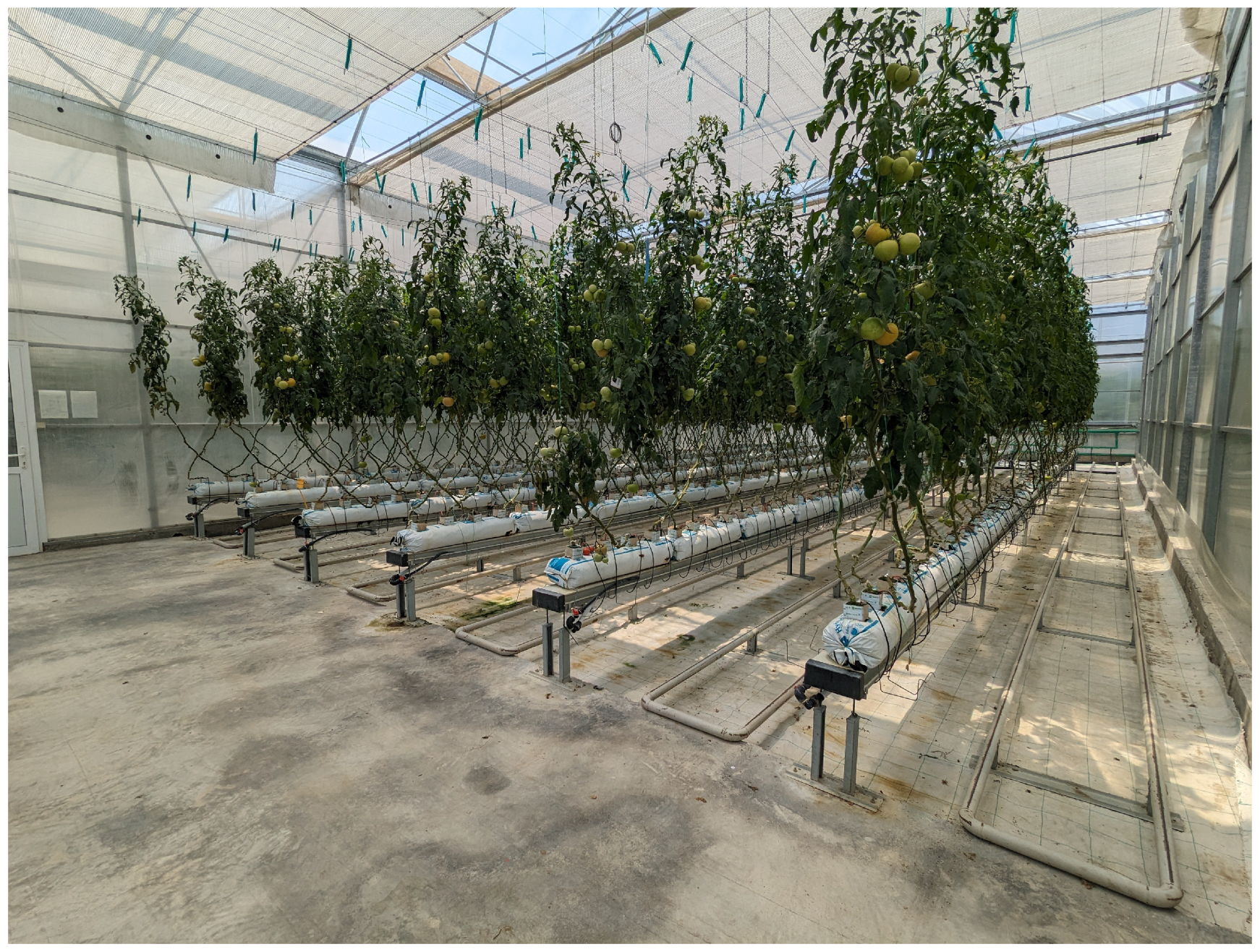
3. Materials and Methods

In this section, a detailed description of the essential elements of our navigation system for robotic greenhouses is provided. The effectiveness of these systems is contingent upon the coordination and integration of multiple components, each of which plays a crucial role in the overall operational efficiency. A thorough analysis of our strategy follows, starting with an explanation of the mobile platform that serves as the tangible foundation of our robotic system. Subsequently, the fundamental elements of perception are elaborated upon, involving the utilization of sensors and data collection methods to attain environmental awareness. In the section that follows, localization and mapping techniques, which are essential for the construction of an accurate representation of the greenhouse environment, will be discussed. Finally, the complexities of navigation algorithms, which enable the robot to navigate within the greenhouse environment with precision and efficiency, will be investigated. By conducting an exhaustive analysis of these constituent elements, we aim to provide a thorough understanding of our greenhouse robotic navigation system, thereby shedding light on its capabilities and potential applications.

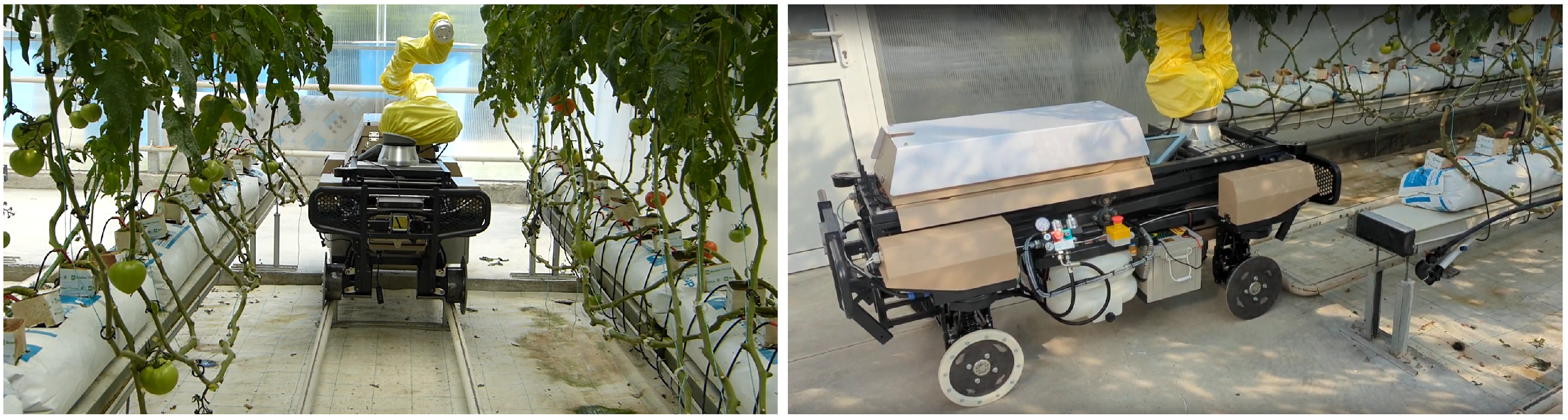
3.1. Robotic Platform

The mobile platform employed in the proposed navigation pipeline is an omnidirectional fully Autonomous Mobile Robot (AMR), featuring a UR10e cobot placed on a scissors lift platform. The UR10e cobot has a working envelope of 1.2 m and the scissors lift has 2.5 m reach. This combination greatly extends the system’s workspace, reaching from close to ground level up to 3.5 m high, making it suitable for inspection and 3D spot spraying purposes in large-scale greenhouses. It allows for the use of biopesticides and non-hazardous pesticides from an integrated spray tank. The AMR enables the detection and identification of insects such as whiteflies and black aphids [27] and fungal diseases such as Botrytis cinerea [28] using an AI-based system equipped with RGB and a multispectral camera, tuned at 460, 540, 640, 700, 775, and 875 nm wavelengths to include wavelengths from the visible and near infrared (NIR) spectrum. The data collected from the imaging devices on the AMR are analyzed in a robust Decision Support System [29]. The robot is equipped with four metallic wheels that provide a dual configuration, allowing the robot to operate simultaneously on the greenhouse rails and the flat surface of the headland area. These wheels are quickly exchangeable with rubber wheels, enabling this robotic platform to navigate in outdoor environments and open fields. This configuration allows the robot to target multiple use cases, both indoors and outdoors, and different crops including cucumbers, tomatoes, lettuce, and peppers.
A fully integrated multisensory stack supports the autonomous navigation and mapping software components. A forward-facing 3D LiDAR sensor, Livox Avia, provides dense and robust distance measurements in the main direction of movement, as depicted in Figure 1. Two stereo RGB cameras, ZED2i, are placed on the front and rear sides of the robot, providing both dense depth measurements as well as RGB images for semantic purposes. Safety requirements for the robot are met through the strategic placement of two 2D YDLIDAR TG30 laser scanners positioned diagonally across from each other. Regarding motion estimation, the robot is equipped with the Xsens MTi-680G Inertial Measurement Unit (IMU) sensor, wheel odometry encoders, and a GNSS module for outdoor operations. The robotic platform is depicted in Figure 1, while certain specifications are described in Table 1. The payload is determined as an additional weight to the robot when it is fully loaded. This includes a full tank of pesticide, the end effector attached to the UR10e robot, which carries all the sensors, as well as the spraying mechanism. In addition, the robot possesses the capability to transport an additional 15 kg.

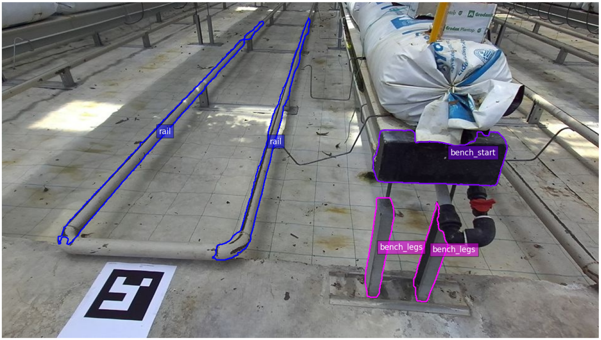
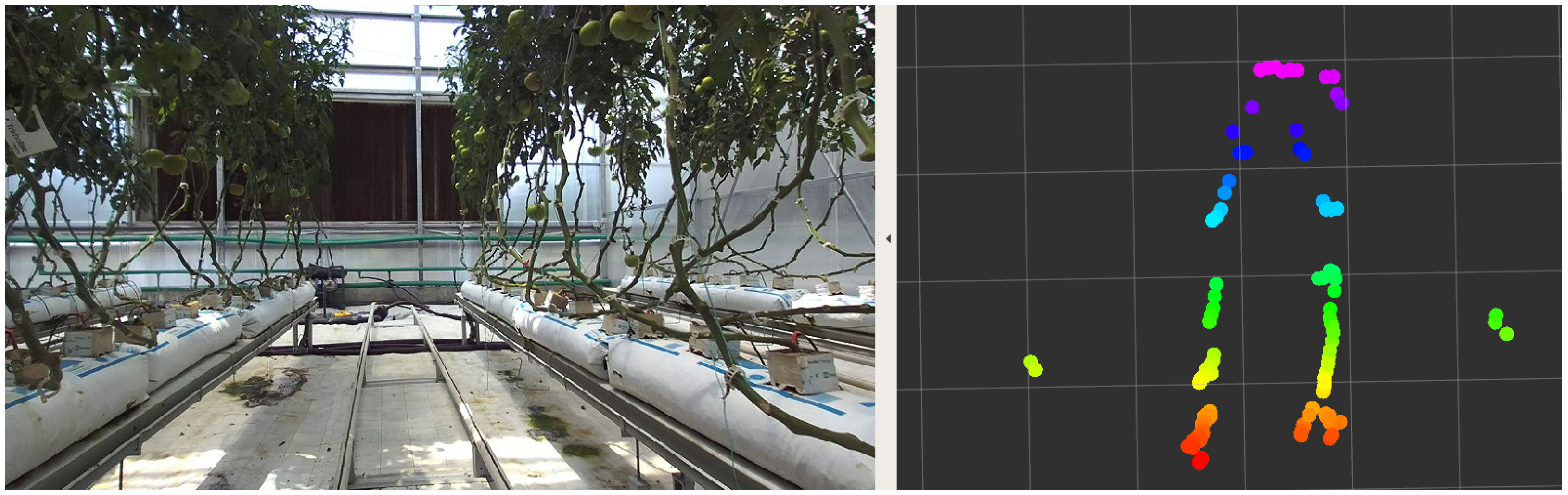
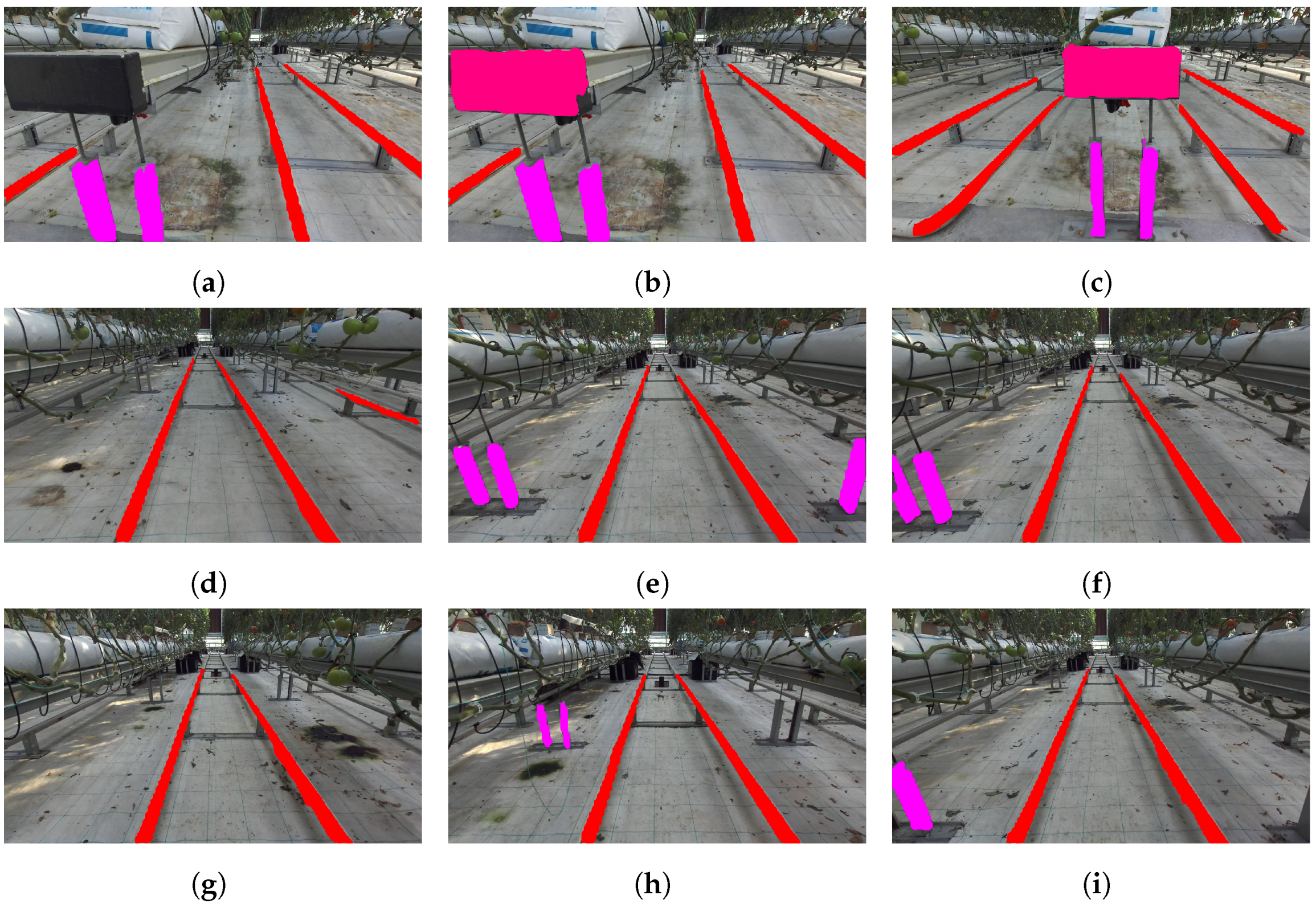
3.2. Greenhouse Semantic Segmentation

To establish a seamless navigation framework, the main objective is to harness the semantic information of the greenhouse environment within our solution’s perception system. The focus is on the semantic attributes that are intrinsic to the greenhouse’s structure, as they can serve as valuable resources for mapping and autonomous navigation tasks. Specifically, two important greenhouse components are of interest: the heating pipelines, also known as “rails”, and the bench start and bench legs, located at the beginning of each corridor and referred to as “endpoints”. The former can be used as a landmark for the lateral position and orientation of a corridor, while the latter indicates the corridor start point in the longitudinal direction. Typically, the rails are placed in the middle of the corridor, forming long horizontal lines with a fixed separation distance d r . The corridor endpoints of the greenhouse used in the experimental evaluation are indicated by the black plastic covers of the benches as shown in Figure 2 in purple, while the bench legs are displayed in pink and the rails in blue.
YOLOv8 [30] is the most recent advancement in the YOLO series of architectures, renowned for their object detection capabilities. In order to ensure real-time performance for our system, the small architecture (YOLOv8s-seg) is selected. Despite its reduced size, this architecture is still capable of effectively handling the segmentation task, while keeping the inference time to a minimum.
For our specific task, the primary interest lies in the acquisition of a binary mask, denoted as M c , which is used to represent the pixels belonging to each individual class c (in this case, rails and endpoints). The output of the YOLOv8s-seg network consists of a list of pixel mask instances, along with their respective assigned class labels. This output can be represented as M = { M c , 0 , M c , 1 , , M c , N | c 0 , 1 } , where N represents the number of instances of class c present in the image.
To obtain the desired binary mask M c , a union operation is applied over all instances of class c identified by the network. This is represented as follows:
M c = i = 0 N M c , i .
Through this approach, the individual masks associated with each instance of class c are effectively combined into a single comprehensive mask M c , thereby providing the desired segmentation result. Each individual mask M c for the segmentation categories (rails, bench legs, and bench start) is depicted in Figure 3.
The pre-trained YOLOv8 models do not by default include the classes’ rails and endpoints. Therefore, a process of fine-tuning was required to utilize the network segmentation capabilities. A small dataset of fewer than 200 images was acquired manually inside the greenhouse, with images depicting views from multiple operational areas. The simplicity of this task allowed YOLOv8 to be instantly fine-tuned using the default parameters, using a small set of images and without extensive human annotation. Rails and corridor endpoints have an unchanged appearance, the lighting conditions remain the same throughout the day and the shapes of these objects are clearly separated from the background scene, leading to an overall simple task that can be handled easily by state-of-the-art segmentation neural networks, such as YOLOv8.

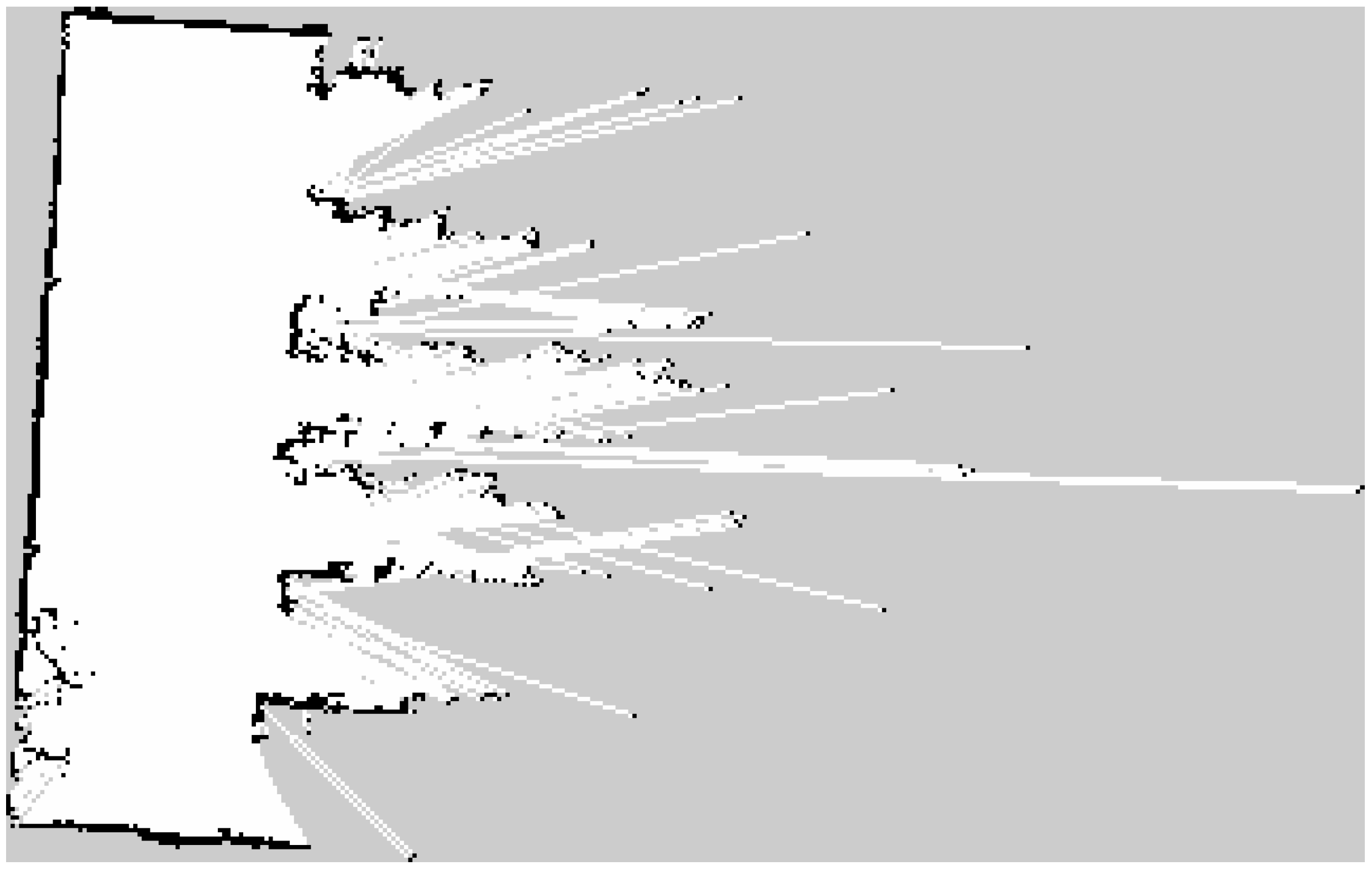
3.3. Mapping & Localization

The operation of the robotic platform in the greenhouse requires the generation of an accurate occupancy grid map, especially for the headland area, in order to localize efficiently within the environment. As depicted in Figure 4, the greenhouse area consists of six crop rows and, consequently, six row corridors. Each corridor contains a set of rails extending up to the end of the crop row, while on the end of the row there is a flat vertical surface, the wall of the greenhouse. The beginning of all rows is connected to the greenhouse headland, a flat surface where the robot can freely navigate. The generated occupancy grid map is utilized in order to properly localize in the greenhouse headland and support the placement of the robot at the beginning of each row. Localization within the crop rows is handled differently, and an occupancy grid map is not needed in this case.
The headland area is characterized by aligned corners and distances well within the sensors’ range, making it well-suited for employing standard 2D mapping algorithms relying on laserscan measurements. The output of the mapping procedure is depicted in Figure 5, which is generated using GMapping [31]. Localization inside the headland is performed using Adaptive Monte Carlo Localization [32], which uses a particle filter to track the robot’s pose within the known 2D map.
Mapping in between the corridors is not needed since the operation of the robot in the corridors is fully constrained and a map will not provide any additional positional information. The corridors are characterized by a high degree of repeatability, and the actual freespace can vary significantly due to the crop state. For this reason, localization cannot be handled by approaches such as the Adaptive Monte Carlo Localization (AMCL), and we employ a different module that utilizes the current robot perception. Since the greenhouse rails have a fixed length and standardized distance from the greenhouse boundaries, they are used in order to localize the robot while traversing the rows.
Specifically, for this process, called in-row localization, the robot needs to calculate its distance from the vertical wall that is located within its field of view. In order to properly calculate that distance, the average range of all valid laser measurements that are located within the angle of interest is calculated. In Figure 6, the measurements of the robot while approaching the corridor end are depicted. The in-row localization module becomes operational after the robot has successfully completed the transition onto the tracks. The initial pose of the robot before to transitioning into the in-row state is recorded and then supplied to the AMCL algorithm when the robot switches back to headland navigation.
The objective of the localization process is to extract the complete 2D pose of the robot (x, y, θ ) throughout time. We approach this as a nonlinear dynamic system, described as:
x k = f ( x k 1 ) + w k 1 ,
where x k is the robot’s pose for a given time k, f describes a nonlinear transition function and w k 1 represents the process noise, which is normally distributed.
The overall localization system leverages a fusion of the aforementioned two cases along with the robot’s sensor data obtained by the robot. Specifically, an Extended Kalman Filter (EKF) performs the fusion of wheel odometry with IMU measurements and either the output of AMCL for headland operation or the output of in-row localization for corridor traversal. The 15-dimensional vector x k contains the following states:
  • Three dimensional (3D) pose (x, y, z);
  • Three dimensional (3D) orientation ( Φ , ψ , θ );
  • The corresponding velocities of the above (x , y , z , Φ , ψ , θ );
  • The acceleration of the 3D pose (x , y , z ).
Table 2 provides a detailed configuration of the modalities that contribute to the EKF localization module, mentioning only the states that are directly related to the estimated 2D pose of the robot.
The input of the EKF from all modalities is expressed as:
z k = h ( x k ) + u k ,
where z k is the sensor measurements at time k, h is a nonlinear sensor model that maps the state into measurement space, and u k represents the sensor noise model. As shown in Table 2, absolute pose and orientation information are only reported by AMCL and in-row localization. Wheel odometry and IMU measurements provide linear and angular velocities and linear accelerations, due to the nature of IMU devices that measure differential values.

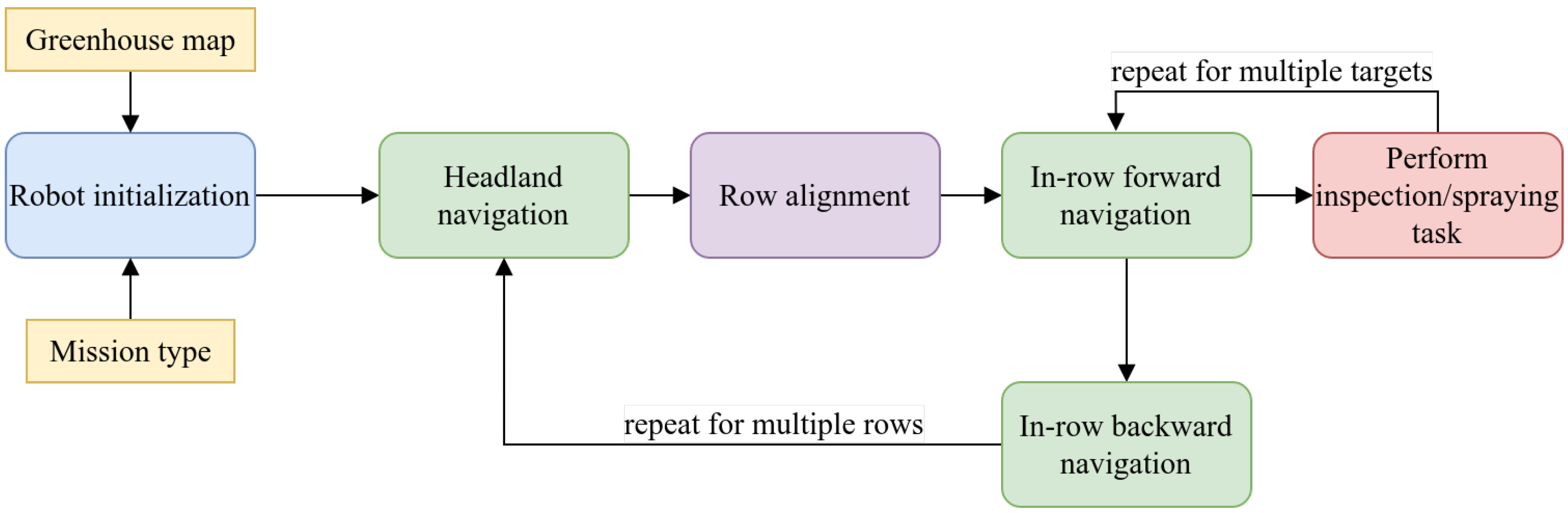
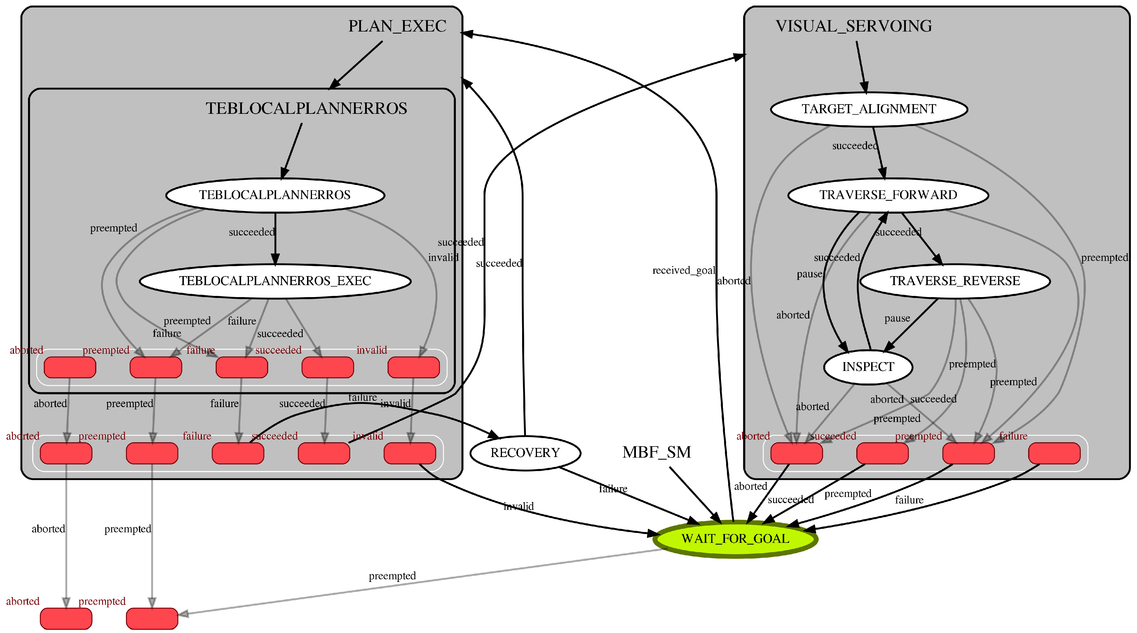
3.4. Navigation Strategy

A well-defined policy is essential for the robot’s operation within the greenhouse, necessitating a meticulous inspection process that is orchestrated through a Finite State Machine that dictates the sequence of actions the robot must execute and the specific targets it must visit. The overall pipeline and the procedures that need to be organized are depicted in Figure 7.
The initial stage in the pipeline commences with robot initialization, encompassing the acquisition of both the greenhouse occupancy grid map and the user’s mission instructions, which specify the rows to be inspected. This phase also includes the configuration of crucial operational components such as localization and the determination of the action sequence required to complete the designated mission. The navigation of the robotic platform towards the target row first requires the navigation within the headland, at one of the pre-known targets on the map. Details regarding this navigation step are described in Section 3.5. The next step is to perform the robot alignment with the corridor rails (Section 3.6) in order to prepare for the in-row forward navigation task (Section 3.7), which follows. The robot iteratively performs all the required inspection tasks within the operating row and, once these targets are completed, the robot performs in-row backward navigation in order to place itself back on the headland. This process is repeated for all required rows that the robot must inspect until the completion of the mission.
In order to orchestrate the sequence of actions effectively and combine it with the Robot Operating System (ROS) navigation stack, we utilize the SMACH library (http://wiki.ros.org/smach (accessed on 5 October 2023)). SMACH serves as an interface for modular software components, providing direct communication with the complete ROS architecture, upon which the robotic platform is built. Regarding the navigation tasks of the robot, we employ Move Base Flex [33] in order to allow the simultaneous operation of multiple planners while providing feedback for all requested actions. Through this approach, an integrated solution for both task planning and navigation operations is provided. A visualization of the complete State Machine is shown in Figure 8.
The robot initialization is equivalent to the WAIT_FOR_GOAL state. When a mission is provided to the robot, there is a transition to the PLAN_EXEC block, which contains the headland planning that is performed by the Timed Elastic Band (TEB) Local Planner. When that block finishes successfully, there is a transition to the VISUAL_SERVOING block, which is responsible for the in-row processes. Specifically, the robot performs the TARGET_ALIGNMENT phase once, followed by an iterative process between the states TRAVERSE_FORWARD, INSPECT and TRAVERSE_BACKWARD. When the in-row task is completed, the FSM returns to the WAIT_FOR_GOAL state again. It must be noted that any failure that may occur throughout the entire operation returns to a common state, which is reported as invalid, aborted, or a failure, and then to the initialization state.

3.5. Headland Navigation

The headland navigation task requires the robot to efficiently navigate through the predefined targets that are located at the beginning of each corridor while avoiding any potential obstacles in the area. As shown in Figure 9, the greenhouse environment consists of six corridors, and the corresponding six different target waypoints are depicted on the map with green arrows. The user manually annotates these targets on the generated occupancy grid map, which facilitates switching between corridors and pinpointing their precise locations.
During the mission execution, the robot is not required to visit all N targets that are available on the map. According to the mission description, a sequence between the required targets n i , i ( 0 , N ) is generated using linear segments to connect the waypoints. A TEB local planner is responsible for generating new trajectories that respect the robot kinematics as well as keeping the essential distance from obstacles. The local planner operates on a local costmap that updates in real-time with the input from the laser scanners and provides accurate, collision-free trajectories within the restricted headland area. The omni-directional platform enables simple transitions between waypoints without requiring complex path planning strategies. It is expected and efficient for the local plan to coincide with the linear segments of the global plan when there are no obstacles nearby.

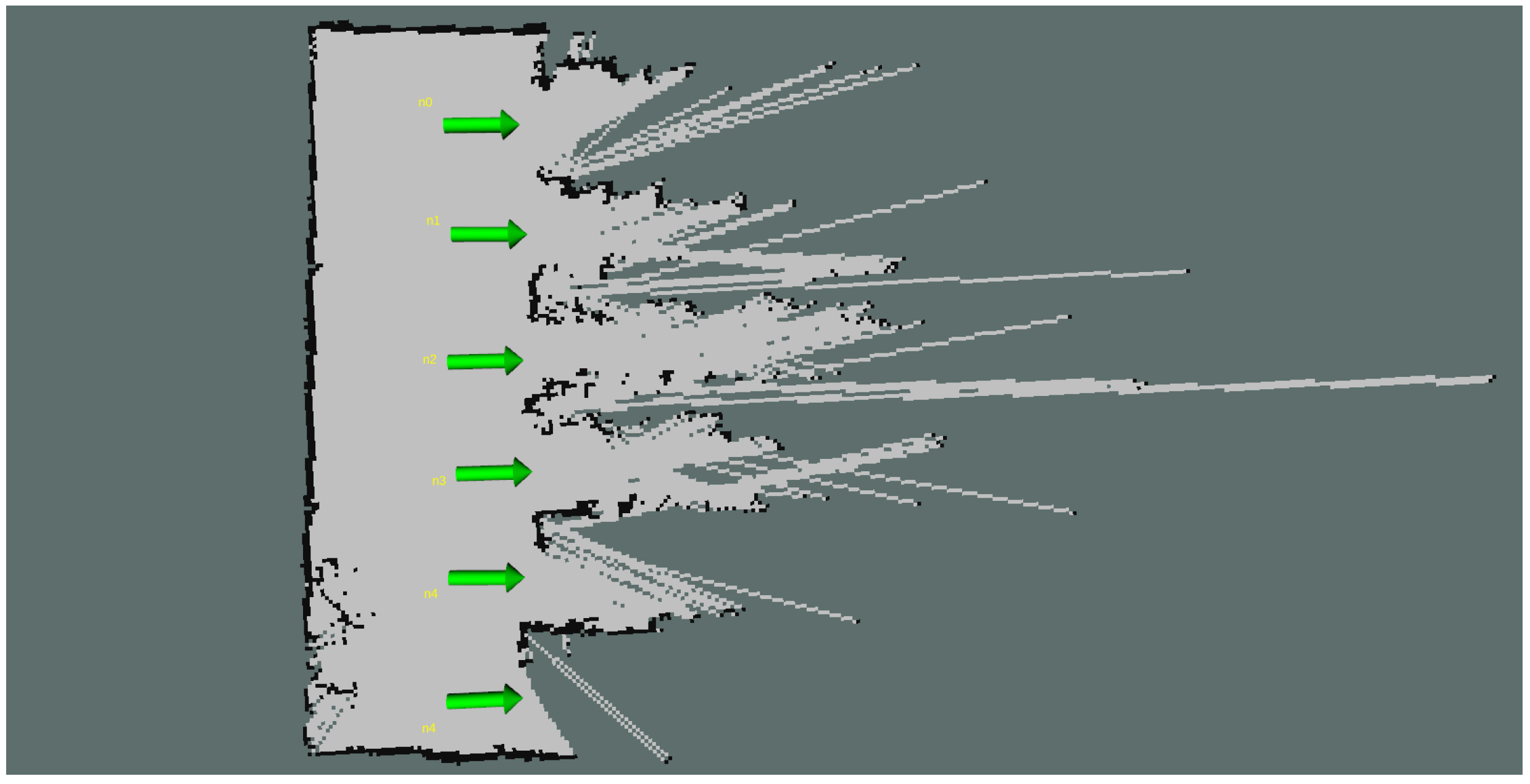
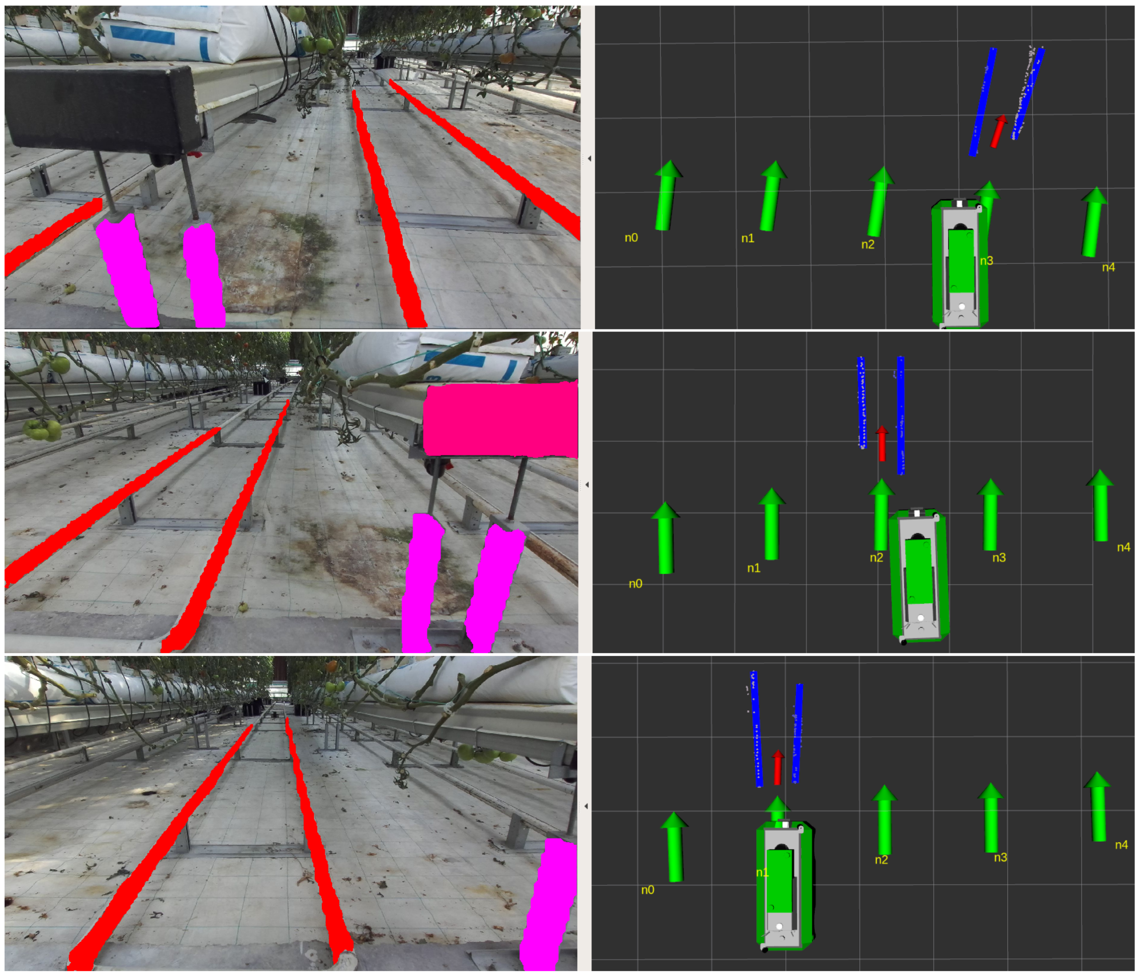
3.6. Rails Alignment

The navigation of the robot through the greenhouse rows necessitates the precise alignment of the platform with the rails in order to safety traverse the heating pipes and complete the inspection task. Inaccurate alignment may result in severe problems with regards to the operation’s safety and the robotic platform’s stability. The rails alignment task uses the results of semantic segmentation on the greenhouse environment, specifically the position of the rails in 2D and 3D space, to calculate the optical velocity and steering commands that will align the robot precisely with the rails.
The primary objective of this task is to transform the binary mask M, which represents the rails, into a set of three-dimensional points. The aforementioned process of transformation is accomplished through the integration of the outcomes of semantic segmentation with the depth data obtained from the stereo camera system. Given that the depth image D is readily available from the camera, it is possible to immediately convert each pixel m ( i , j ) M into a three-dimensional point p ( x , y , z ) by utilizing the camera’s intrinsic parameters c x , c y , f x , f y . The depth z of a point m ( i , j ) in the binary mask can be obtained directly from the point d ( i , j ) D . The utilization of a back-projection technique between the two coordinate systems yields the final set of points that constitute the rails in real-world coordinates. Equation (4) describes the process of transforming all pixels value m ( i , j ) into three-dimensional points p ( x , y , z ) using the depth information d ( i , j ) .
x = d ( i , j ) × i c x f x y = d ( i , j ) × j c y f y . z = d ( i , j )
The generated point cloud P is post-processed to eliminate outliers and provide the alignment module with only pertinent 3D points. The point cloud is initially transformed into the robot’s coordinate system, and the whole problem is from now on expressed relative to the robot body. Since the points of interest are in close proximity to the area in front of the robot, a passthrough filter on the x-axis is implemented and all points beyond a predetermined distance are discarded. In addition, the robot’s approximate location within the corridor enables the use of a passthrough filter on the y-axis to disregard noisy measurements from the robot’s sides. Lastly, the headland’s flat surface and the known height of the rails permit the use of a passthrough filter on the z-axis to remove the floor seamlessly and reject points above the rails. The resultant point cloud is converted into a voxel grid, which downsamples the cloud while preserving its structure.
The subsequent phase entails the transition from discrete data points into a mathematical representation suitable for the alignment procedure. This is accomplished through a RANSAC [34] filtering process that iteratively formulates linear segments that effectively encapsulate the salient features within the 3D point cloud. RANSAC is a robust and widely adopted algorithm, renowned for its ability to identify these linear structures amidst potential noise and outliers within the data.The equation for the line model is denoted by Equation (5). The line coefficients comprise the coordinates of a point x 0 , y 0 , z 0 residing on the line, as well as the three-dimensional vector a , b , c that describes the line direction.
L i = a · x + b · y + c · z + d = 0 d = ( a · x o + b · y 0 + c · z 0 ) .
The lines extracted, denoted as L i , are arranged in ascending order based on their vertical location relative to the robot, and a search process is initiated in order to extract the pair that the robot must align with. The outcome of RANSAC filtering might generate linear segments that belong on the same line but are expressed with a slightly different equation due to noisy measurements. For this reason, a simple filtering process is applied in order to perform a thresholding comparison regarding the orientation and the parallel distance of line pairs. Each linear segment that does not satisfy the minimum distance and angle difference among neighboring linear segments is identified as a duplicate and is removed.
The prior knowledge of the precise distance d r between corridor rails facilitates a pair matching algorithm for all lines expressed in 3D coordinates. Given N linear equations and by taking advantage of their sorted placement, we compare the distance between L i and L i + 1 . where i ( 0 , N 1 ) . Each pair whose distance is almost equal to d r is considered a rail. In the case of multiple rails being detected, it becomes essential to match the rail’s position with the desired row’s target waypoints and to keep the closest one, which comprises L r i g h t and L l e f t . For both L r i g h t and L l e f t we extract the closest point to the robot body, p r i g h t and p l e f t , and their average is calculated as p m i d d l e = p r i g h t + p l e f t 2 .
The alignment procedure involves an initial tuning of the robot’s angle, followed by the adjustment of the y-axis and subsequently the x-axis, with the possibility of iterative refinement if necessary. At each timestep the robot calculates its divergence from p m i d d l e , which is expressed as d θ , d y and d x . The velocity components that must be calculated are υ θ , υ y and υ x . The adjustment of each one relies on the definition of a control gain, a discrete value that affects directly the speed and the precision of the robot movements and is defined separately as g θ , g y and g x . The three conditions that are consistently checked for their value are the following:
d θ 0 d y 0 d x 0 .
Based on the results obtained from the aforementioned conditions, the velocity vector that is supplied to the robot undergoes modification. When there is misalignment in the orientation angle θ , the velocity vector primarily comprises angular commands, restricting motion to the z-axis:
υ = ( υ x , υ y , υ θ ) = ( 0 , 0 , k θ ) .
Conversely, when there is proper angular alignment but misalignment in the y-axis placement, the velocity vector assumes a configuration emphasizing lateral motion along the y-axis:
υ = ( υ x , υ y , υ θ ) = ( 0 , k y , 0 ) .
Finally, when both proper angular alignment and y-axis placement are achieved, the velocity vector is adjusted to prioritize motion along the x-axis:
υ = ( υ x , υ y , υ θ ) = ( k x , 0 , 0 )
The alignment process is completed when all three conditions of Equation (6) are met, which implies that the robot is located on the greenhouse rails and the navigation method is performed differently, as described in Section 3.7 below.

3.7. Rails Navigation

The navigation of the mobile platform within the rows of the greenhouse environment is rather straightforward due to the strict limitations imposed by the current infrastructure. Within the confines of this particular scenario, the mobility of the robot is constrained to only two directions: forward and backward. Consequently, any instructions related to velocity that do not belong to the linear x-axis are deemed inconsequential and swiftly disregarded. As the robot traverses the greenhouse rails with diligence, determining its precise location becomes crucial. This precision is necessary to ensure that the robot can stop with pinpoint accuracy in predetermined areas where essential inspection duties are scheduled. To achieve this, the robot incorporates an in-row localization process, as described in Section 3.3.
After successfully navigating an entire corridor, the robot transitions into a backward movement mode. The provision of negative linear velocity commands to the robot controller serves the purpose of directing the robot towards the initial point of the row. Upon dismounting from the rails, the robot is capable of either moving to an alternative row or terminating the mission. The termination of backward movement, and rail navigation in general, is triggered when the robot’s field of view encompasses the endpoints of the rows, as detected by the semantic segmentation module.

4. Experimental Evaluation

This section provides a comprehensive overview of the trials that have been performed to evaluate the performance and efficacy of our greenhouse robotic navigation system. Our experimental setup includes a real-world hydroponic greenhouse environment in the University of Thessaly, where the robot, which was described in Section 3.1, was assigned with the task of autonomously navigating rows of crops and performing inspection tasks. To assess its navigation precision and adaptability, we introduced varying degrees of misalignment and obstacles, simulating real-world challenges.

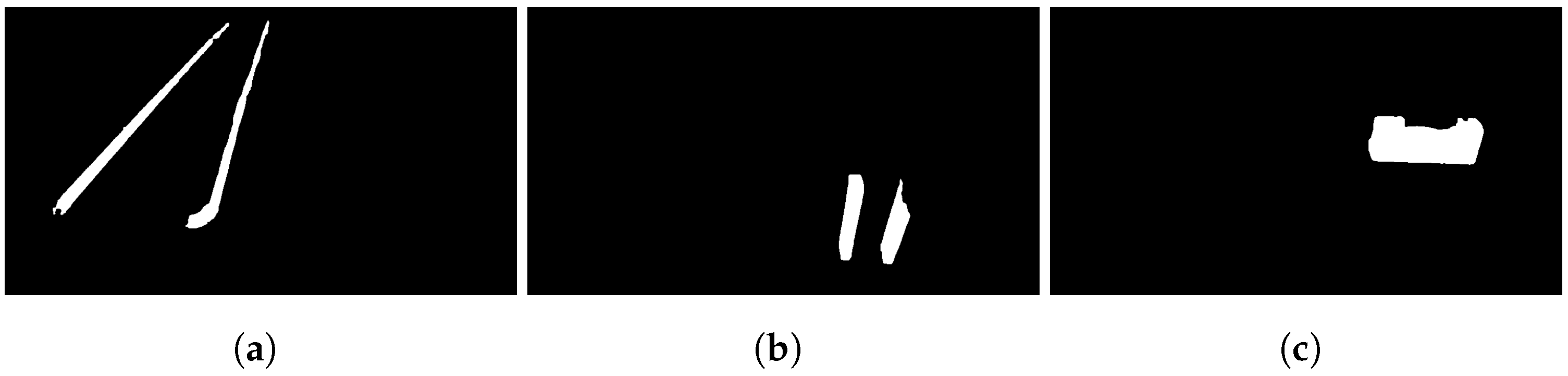
4.1. Semantic Segmentation

In order to evaluate the fine-tuning efficiency of YOLOv8 on the desired semantic segmentation task, an 80/20 split was applied in order to extract the validation data. So, 160 images from the greenhouse were used for training purposes and 40 of them were used for validation, all captured using a handheld system with a ZED2 camera. As already mentioned in Section 3.2, the simplicity of the segmentation task resulted in high accuracy segmentation results in the validation set. The actual efficiency of the proposed method was evaluated using data that were collected during the actual operation of the robotic platform within the greenhouse environment. In Figure 10, qualitative results on the YOLOv8 segmentation task taken directly from the robot camera are depicted, where it becomes evident that the robot is able to efficiently segment the rails, the bench start, and the bench legs within the image. For an input image size of 640 pixels, the inference of YOLOv8n required only 11.1 ms for a low-end GPU device.
The issues that can be easily perceived from the qualitative results are that the robot does not always properly segment the branch start (Figure 10a,b), side rails can be detected while the robot is aligned with the desired rail (Figure 10c), and bench legs are not always detected for the legs that are located in the middle of the corridor (Figure 10d,h). However, such issues do not affect the robustness of the navigation method, as will be shown in the following section.

4.2. Rails Alignment

The evaluation of the rails alignment process was performed with two different approaches. The initial one is to evaluate the qualitative results that occur from the rails extraction algorithms during the actual operation of the robotic platform. Apart from the segmentation of the rails, the algorithm must select the appropriate set of rails that is visible within its field of view and extract the linear segment properly. Finally, the algorithm extracts an alignment target that directly affects the extraction of the velocity commands. The above results are depicted in Figure 11. Specifically, for three given scenes, we visualize the outputs of the rails alignment algorithm. The nodes that comprise the topological map are shown with the green arrows. The selected rails are visualized with the blue lines, while the alignment target is shown with the red arrow. The robotic platform can successfully extract the alignment target properly from different viewing points, resulting in the proper placement of the robotic platform in front of the corridor rails.
The second part of the evaluation is the observation of the velocity commands that were provided to the robotic platform, so as to align with the rails and transfer itself on the heating pipes. It is important that the robot receives continuous velocities and that there are no spike measurements that could affect the overall smooth operation of the robot.
In Figure 12, the velocities that the robot received while performing a route are depicted. The time moment t that the robot enters row n 1 is depicted with the first vertical black dashed line. From that moment, the robot was moving only forward and backward, as can be seen by the linear-y and angular-z commands that are equal to 0. The time moment t when the robot exited the row n 0 and moved to the right for switching to row n 2 is annotated with the second black dashed line. The robot reached the beginning of n 2 and stopped its motion. In Figure 13, we depict the trajectory that the robot followed through the above-mentioned velocity commands in order to align with the corridor rails. This information is provided by the localization module and outlines how the robot approaches the desired row and docks on the rails.

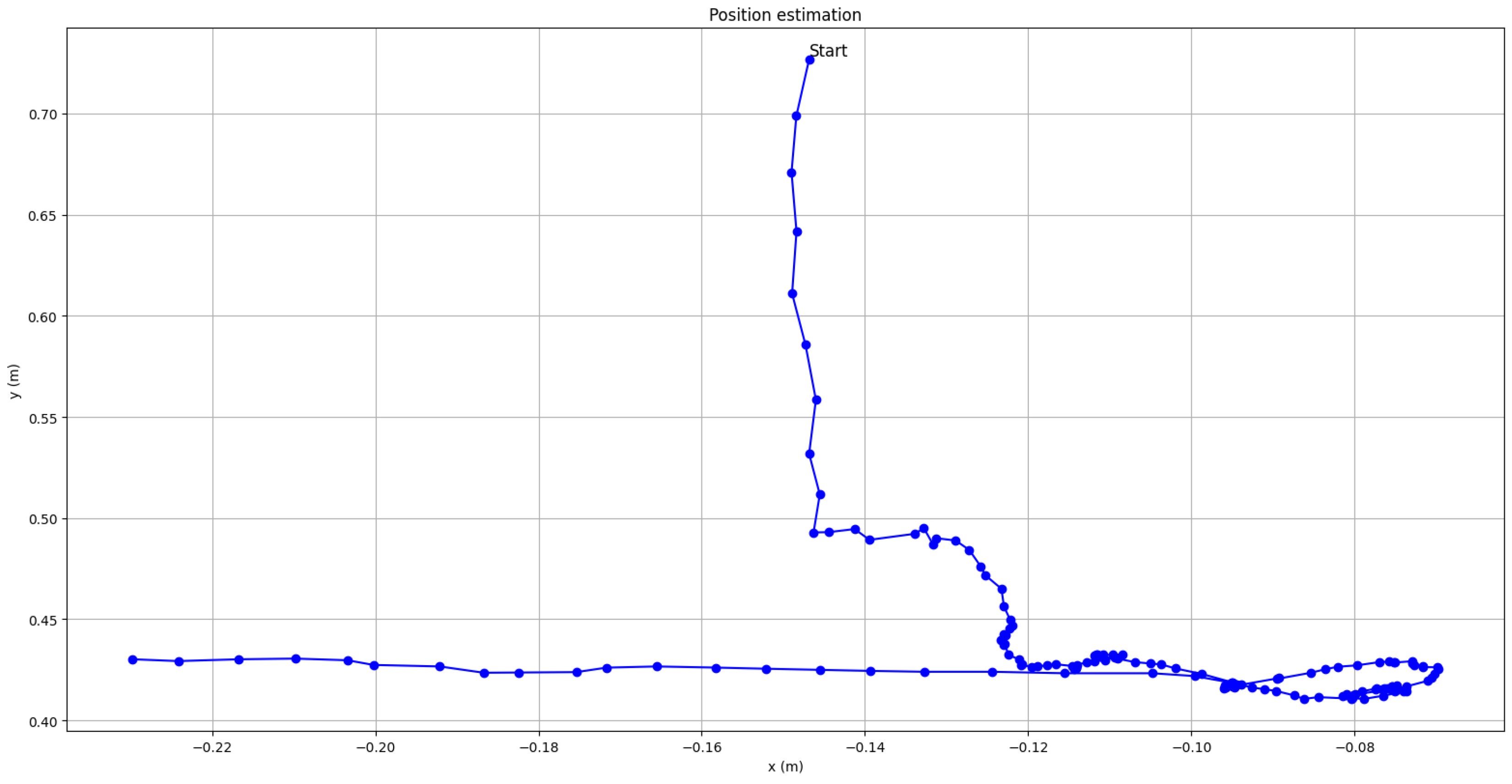
4.3. In-Row Localization

For the above-mentioned route that the robot executed, the in-row localization output is depicted in Figure 14. The straight and continuous position estimates indicate the overall smooth calculation of the robot’s distance to the greenhouse wall.

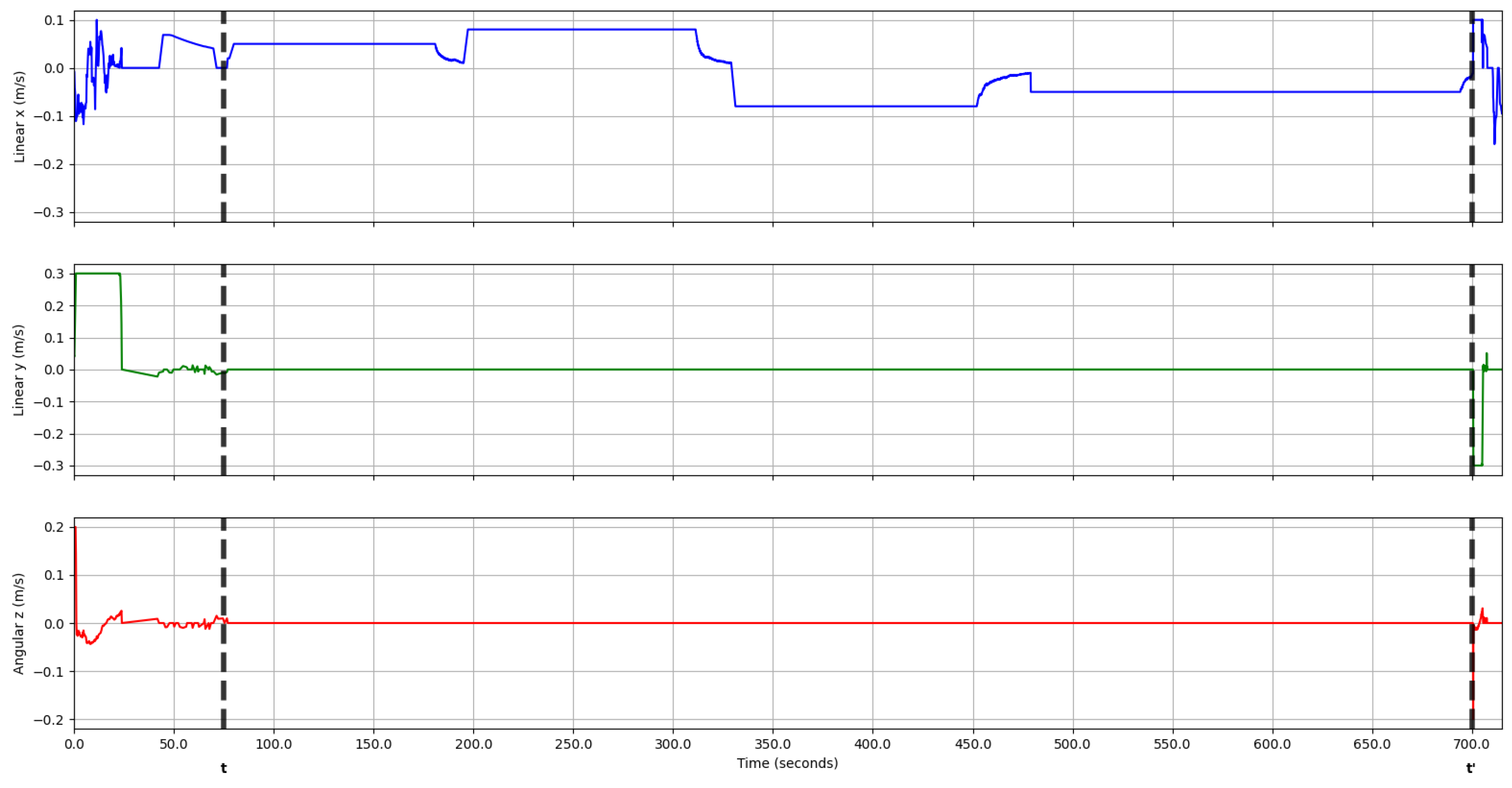
4.4. Closed-Loop Navigation

The successful evaluation of the aforementioned software components allows for the full deployment of the robot towards a fully autonomous mission within the greenhouse environment. The robot was assigned to visit a whole row of crops and then perform its backward movement, until it returns to the headland area. A video demonstrating the closed-loop operation of the robot in a hydroponic greenhouse is available in the Supplementary Material of this paper. The robotic platform is capable of navigating autonomously to the desired row, successfully aligning with the corridor rails, traversing the entire row and finally exiting the row and aligning with the next one.

5. Conclusions

This paper presents a comprehensive navigation framework for holonomic robots operating in confined agricultural environments, namely greenhouses. The well-defined features of the environment, such as the existence of heating pipes that can be used as rails, the flat surface of the headland, and the constant distances within the operating area, enable the full employment of robotic systems towards the automation of tasks such as inspection and spraying. Our navigation framework is based on a custom-built holonomic platform equipped with a robotic manipulator for spraying tasks and wheels that permit operation on both the metallic rails and the headland without the need to switch wheels. The robot’s entire operation is dependent on a well-defined, finite-state machine that coordinates the sequence of actions that must be carried out in accordance with user specifications. The robot’s perception system primarily uses semantic segmentation based on YOLOv8 to segment and comprehend the existence of rails and bench endpoints within its field of view. The robot’s localization is based on an Extended Kalman Filter that integrates sensor measurements with the result of AMCL localization on the headland map and laser measurement-based in-row localization outputs. The robot’s navigation in the headland region is based on the TEB local planner, while in-row navigation is rigidly limited to one-axis velocity commands. Prior to performing in-row navigation, the robot aligns itself with the corridor rails using semantic and depth information from its stereo camera to generate the optimal velocity commands. The efficacy of our navigation framework has been evaluated in a real-world scenario with a robotic platform operating autonomously within a hydroponic greenhouse environment. The evaluation showed that the robot is capable of effectively switching from headland to in-row navigation autonomously while ensuring its safe operation in the environment.
Future work in this domain offers opportunities to enhance and expand our navigation framework for holonomic robots in confined agricultural settings like greenhouses. One promising avenue is the exploration of multi-robot collaboration, allowing multiple robots to work seamlessly within the same environment. Furthermore, ensuring safe and efficient human–robot interaction, enhancing energy efficiency, and integrating with crop monitoring and data analytics systems can further enhance the system’s utility. Finally, scaling up deployment in larger greenhouse facilities and considering commercialization aspects will be pivotal in realizing the full potential of robotic automation in agriculture, ultimately revolutionizing precision agriculture practices.

Supplementary Materials

The following supporting information can be downloaded at: https://www.mdpi.com/article/10.3390/robotics12060146/s1, Video S1: Closed-loop operation of the robot, demonstrating its efficiency in navigating autonomously in a hydroponic greenhouse environment.

Author Contributions

Conceptualization, E.M.P., D.G. and N.F.; methodology, K.T. and A.P.; software, K.T. and A.P.; validation, K.T., A.P., D.G. and A.G.; formal analysis, K.T. and A.P.; investigation, K.T. and A.P.; resources, D.T.; data curation, K.T. and A.P.; writing—original draft preparation, K.T. and A.P.; writing—review and editing, E.M.P. and N.F.; visualization, K.T. and A.P.; supervision, A.G. and D.T.; project administration, E.M.P.; funding acquisition, E.M.P. All authors have read and agreed to the published version of the manuscript.

Funding

Horizon 2020 PestNu project, grant agreement ID 101037128.

Acknowledgments

We would like to thank Nikolaos Katsoulas from the Department of Agriculture Crop Production and Rural Environment, University of Thessaly, Volos, Greece, for providing us access to the greenhouse facilities that were used for our testing.

Conflicts of Interest

The authors declare no conflict of interest.

Abbreviations

The following abbreviations are used in this manuscript:
AMRAutonomouw Mobile Robot
AMCLAdaptive Monte Carlo Localization
APFArtificial Potential Field
DWADynamic Window Approach
EKFExtended Kalman Filter
GNSSGlobal Navigation Satellite System
IMUInertial Measurement Unit
LiDARLight Detection and Ranging
RANSACRANdom SAmple Consensus
RGBRed Green Blue
TEBTimed Elastic Band
UAVUnmanned Aerial Vehicle
UVUltraviolet
YOLOYou Only Look Once

References

  1. Sarkar, S.; Gil, J.D.B.; Keeley, J.; Jansen, K. The Use of Pesticides in Developing Countries and Their Impact on Health and the Right to Food; European Union: Maastricht, The Netherlands, 2021. [Google Scholar]
  2. Sharma, A.; Kumar, V.; Shahzad, B.; Tanveer, M.; Sidhu, G.P.S.; Handa, N.; Kohli, S.K.; Yadav, P.; Bali, A.S.; Parihar, R.D.; et al. Worldwide pesticide usage and its impacts on ecosystem. SN Appl. Sci. 2019, 1, 1446. [Google Scholar] [CrossRef]
  3. Balaska, V.; Adamidou, Z.; Vryzas, Z.; Gasteratos, A. Sustainable Crop Protection via Robotics and Artificial Intelligence Solutions. Machines 2023, 11, 774. [Google Scholar] [CrossRef]
  4. Vatistas, C.; Avgoustaki, D.D.; Bartzanas, T. A systematic literature review on controlled-environment agriculture: How vertical farms and greenhouses can influence the sustainability and footprint of urban microclimate with local food production. Atmosphere 2022, 13, 1258. [Google Scholar] [CrossRef]
  5. Bagagiolo, G.; Matranga, G.; Cavallo, E.; Pampuro, N. Greenhouse Robots: Ultimate Solutions to Improve Automation in Protected Cropping Systems—A Review. Sustainability 2022, 14, 6436. [Google Scholar] [CrossRef]
  6. Prathibha, S.; Hongal, A.; Jyothi, M. IoT based monitoring system in smart agriculture. In Proceedings of the 2017 International Conference on Recent Advances in Electronics and Communication Technology (ICRAECT), Bangalore, India, 16–17 March 2017; IEEE: Piscataway, NJ, USA, 2017; pp. 81–84. [Google Scholar]
  7. Abhiram, R.; Megalingam, R.K. Autonomous Fertilizer Spraying Mobile Robot. In Proceedings of the 2022 IEEE 19th India Council International Conference (INDICON), Kochi, India, 24–26 November 2022; pp. 1–6. [Google Scholar] [CrossRef]
  8. Fountas, S.; Mylonas, N.; Malounas, I.; Rodias, E.; Hellmann Santos, C.; Pekkeriet, E. Agricultural robotics for field operations. Sensors 2020, 20, 2672. [Google Scholar] [CrossRef]
  9. Grimstad, L.; Zakaria, R.; Le, T.D.; From, P.J. A novel autonomous robot for greenhouse applications. In Proceedings of the 2018 IEEE/RSJ International Conference on Intelligent Robots and Systems (IROS), Madrid, Spain, 1–5 October 2018; IEEE: Piscataway, NJ, USA, 2018; pp. 1–9. [Google Scholar]
  10. Winterhalter, W.; Fleckenstein, F.; Dornhege, C.; Burgard, W. Localization for precision navigation in agricultural fields—Beyond crop row following. J. Field Robot. 2021, 38, 429–451. [Google Scholar] [CrossRef]
  11. Chan, S.H.; Wu, P.T.; Fu, L.C. Robust 2D indoor localization through laser SLAM and visual SLAM fusion. In Proceedings of the 2018 IEEE International Conference on Systems, Man, and Cybernetics (SMC), Miyazaki, Japan, 7–10 October 2018; IEEE: Piscataway, NJ, USA; pp. 1263–1268. [Google Scholar]
  12. Chen, H.; Lan, Y.; Fritz, B.K.; Hoffmann, W.C.; Liu, S. Review of agricultural spraying technologies for plant protection using unmanned aerial vehicle (UAV). Int. J. Agric. Biol. Eng. 2021, 14, 38–49. [Google Scholar] [CrossRef]
  13. Bellicoso, C.D.; Bjelonic, M.; Wellhausen, L.; Holtmann, K.; Günther, F.; Tranzatto, M.; Fankhauser, P.; Hutter, M. Advances in real-world applications for legged robots. J. Field Robot. 2018, 35, 1311–1326. [Google Scholar] [CrossRef]
  14. McCool, C.; Perez, T.; Upcroft, B. Mixtures of lightweight deep convolutional neural networks: Applied to agricultural robotics. IEEE Robot. Autom. Lett. 2017, 2, 1344–1351. [Google Scholar] [CrossRef]
  15. Yan, B.; Fan, P.; Lei, X.; Liu, Z.; Yang, F. A real-time apple targets detection method for picking robot based on improved YOLOv5. Remote Sens. 2021, 13, 1619. [Google Scholar] [CrossRef]
  16. Xiong, Y.; Ge, Y.; Grimstad, L.; From, P.J. An autonomous strawberry-harvesting robot: Design, development, integration, and field evaluation. J. Field Robot. 2020, 37, 202–224. [Google Scholar] [CrossRef]
  17. Kleitsiotis, I.; Mariolis, I.; Giakoumis, D.; Likothanassis, S.; Tzovaras, D. Anisotropic Diffusion-Based Enhancement of Scene Segmentation with Instance Labels. In Proceedings of the Computer Analysis of Images and Patterns: 19th International Conference, CAIP 2021, Virtual Event, 28–30 September 2021; Springer: Berlin/Heidelberg, Germany, 2021; pp. 383–391. [Google Scholar]
  18. González, R.; Rodríguez, F.; Sánchez-Hermosilla, J.; Donaire, J.G. Navigation techniques for mobile robots in greenhouses. Appl. Eng. Agric. 2009, 25, 153–165. [Google Scholar] [CrossRef]
  19. Jiang, S.; Wang, S.; Yi, Z.; Zhang, M.; Lv, X. Autonomous navigation system of greenhouse mobile robot based on 3D Lidar and 2D Lidar SLAM. Front. Plant Sci. 2022, 13, 815218. [Google Scholar] [CrossRef] [PubMed]
  20. Harik, E.H.C.; Korsaeth, A. Combining Hector SLAM and Artificial Potential Field for Autonomous Navigation Inside a Greenhouse. Robotics 2018, 7, 22. [Google Scholar] [CrossRef]
  21. Wu, C.; Tang, X.; Xu, X. System Design, Analysis, and Control of an Intelligent Vehicle for Transportation in Greenhouse. Agriculture 2023, 13, 1020. [Google Scholar] [CrossRef]
  22. Fei, M.; Wendong, H.; Wu, C.; Sai, W. Design and experimental test of multi-functional intelligent vehicle for greenhouse. In Proceedings of the 2021 4th IEEE International Conference on Industrial Cyber-Physical Systems (ICPS), Victoria, BC, Canada, 10–12 May 2021; IEEE: Piscataway, NJ, USA, 2021; pp. 755–760. [Google Scholar]
  23. Ahmadi, A.; Nardi, L.; Chebrolu, N.; Stachniss, C. Visual servoing-based navigation for monitoring row-crop fields. In Proceedings of the 2020 IEEE International Conference on Robotics and Automation (ICRA), Paris, France, 31 May–31 August 2020; IEEE: Piscataway, NJ, USA, 2020; pp. 4920–4926. [Google Scholar]
  24. Ahmadi, A.; Halstead, M.; McCool, C. Towards Autonomous Visual Navigation in Arable Fields. In Proceedings of the 2022 IEEE/RSJ International Conference on Intelligent Robots and Systems (IROS), Kyoto, Japan, 23–27 October 2022; IEEE: Piscataway, NJ, USA, 2022; pp. 6585–6592. [Google Scholar]
  25. Chen, J.; Qiang, H.; Wu, J.; Xu, G.; Wang, Z.; Liu, X. Extracting the navigation path of a tomato-cucumber greenhouse robot based on a median point Hough transform. Comput. Electron. Agric. 2020, 174, 105472. [Google Scholar] [CrossRef]
  26. Panda, S.K.; Lee, Y.; Jawed, M.K. Agronav: Autonomous Navigation Framework for Agricultural Robots and Vehicles using Semantic Segmentation and Semantic Line Detection. In Proceedings of the IEEE/CVF Conference on Computer Vision and Pattern Recognition, Vancouver, BC, Canada, 18–22 June 2023; pp. 6271–6280. [Google Scholar]
  27. Giakoumoglou, N.; Pechlivani, E.M.; Katsoulas, N.; Tzovaras, D. White flies and black aphids detection in field vegetable crops using deep learning. In Proceedings of the 2022 IEEE 5th International Conference on Image Processing Applications and Systems (IPAS), Genova, Italy, 5–7 December 2022; IEEE: Piscataway, NJ, USA, 2022; pp. 1–6. [Google Scholar]
  28. Giakoumoglou, N.; Pechlivani, E.M.; Sakelliou, A.; Klaridopoulos, C.; Frangakis, N.; Tzovaras, D. Deep learning-based multi-spectral identification of grey mould. Smart Agric. Technol. 2023, 4, 100174. [Google Scholar] [CrossRef]
  29. Pechlivani, E.M.; Gkogkos, G.; Giakoumoglou, N.; Hadjigeorgiou, I.; Tzovaras, D. Towards Sustainable Farming: A Robust Decision Support System’s Architecture for Agriculture 4.0. In Proceedings of the 2023 24th International Conference on Digital Signal Processing (DSP), Rhodes (Rodos), Greece, 11–13 June 2023; IEEE: Piscataway, NJ, USA, 2023; pp. 1–5. [Google Scholar]
  30. Jocher, G.; Chaurasia, A.; Qiu, J. YOLO, Version 8.0.0, Ultralytics: Los Angeles, CA, USA, 2023.
  31. Grisetti, G.; Stachniss, C.; Burgard, W. Improving grid-based slam with rao-blackwellized particle filters by adaptive proposals and selective resampling. In Proceedings of the 2005 IEEE International Conference on Robotics and Automation, Barcelona, Spain, 18–22 April 2005; IEEE: Piscataway, NJ, USA, 2005; pp. 2432–2437. [Google Scholar]
  32. Fox, D.; Burgard, W.; Dellaert, F.; Thrun, S. Monte carlo localization: Efficient position estimation for mobile robots. Aaai/iaai 1999, 343–349. [Google Scholar]
  33. Pütz, S.; Simón, J.S.; Hertzberg, J. Move Base Flex: A Highly Flexible Navigation Framework for Mobile Robots. In Proceedings of the 2018 IEEE/RSJ International Conference on Intelligent Robots and Systems (IROS), Madrid, Spain, 1–5 October 2018; Available online: https://github.com/magazino/move_base_flex (accessed on 5 October 2023).
  34. Fischler, M.A.; Bolles, R.C. Random sample consensus: A paradigm for model fitting with applications to image analysis and automated cartography. Commun. ACM 1981, 24, 381–395. [Google Scholar] [CrossRef]
Figure 1. The mobile robotic platform used in the navigation pipeline. The left image displays the front side of the robot while traversing on the greenhouse’s corridor rails. LiDAR and a stereo camera are attached on this side. The right image displays the side view of the robotic platform with the biopesticide tank and the 2D laser scanners.
Robotics 12 00146 g001
Figure 2. The classes of interest in the greenhouse semantic segmentation task. With blue, we denote the corridor rails; with pink, the bench legs; and with purple, the corridor end points.
Robotics 12 00146 g002
Figure 3. The resulting binary masks for each category of the semantic segmentation task. (a) Rails; (b) Bench legs; (c) Bench start.
Robotics 12 00146 g003
Figure 4. The greenhouse environment consisting of six crop rows and the headland.
Robotics 12 00146 g004
Figure 5. The resulting occupancy grid map from the greenhouse headland using GMapping.
Robotics 12 00146 g005
Figure 6. The robot calculating its distance from the front wall. Closer points are depicted with red, while the furthest points of interest are colored in purple.
Robotics 12 00146 g006
Figure 7. The overall pipeline for greenhouse navigation.
Robotics 12 00146 g007
Figure 8. The Finite State Machine that controls the strategy execution.
Robotics 12 00146 g008
Figure 9. The waypoints located on the start of each corridor.
Robotics 12 00146 g009
Figure 10. Qualitative results on the semantic segmentation task. Subfigures (ai) show different views in the greenhouse. Rails are colored in red, bench legs in magenta and branch start in purple.
Robotics 12 00146 g010
Figure 11. Qualitative results on the rails alignment task. On the left image, the output of the semantic segmentation is depicted. Rails are colored in red, bench legs in magenta and branch start in purple. On the right image, the topological map nodes are denoted with green arrows, the selected rails with blue lines, and the alignment target with a red arrow.
Robotics 12 00146 g011
Figure 12. The velocity commands of the robot for the given route that was followed autonomously. Linear x and y velocities are depicted in blue and green respectively, while angular velocity is depicted in red. Dashed black lines visualize two different time moments when the robot entered and exited a specific row corridor.
Robotics 12 00146 g012
Figure 13. The trajectory of the robot during the corridor alignment process. Discrete robot poses are colored in blue points in map and the complete trajectory is shown with a continuous blue line.
Robotics 12 00146 g013
Figure 14. The results from the in-row localization module while traversing row n 1 and switching to n 2 . With green we denote the pre-defined topological map nodes that are placed in the beginning of each row. With red we denote the robot position during row traversal, as resulted from in-row localization.
Robotics 12 00146 g014
Table 1. Specifications of the robotic platform.
Dimensions2.2 × 0.7 m
Maximum velocity3 km/h
Autonomy4.5 h
Batteries’ typeLiFePO4 Battery 48V-72A
Payload15 Kg
Table 2. Configuration of inputs used by EKF.
Sensorxy θ x y θ x y
Odometry×××××
IMU×××××
AMCL×××××
In-row×××××
✓ represents inputs that affect specific EKF states, while × indicates inputs that do not affect those states.
Disclaimer/Publisher’s Note: The statements, opinions and data contained in all publications are solely those of the individual author(s) and contributor(s) and not of MDPI and/or the editor(s). MDPI and/or the editor(s) disclaim responsibility for any injury to people or property resulting from any ideas, methods, instructions or products referred to in the content.

