

Three-Dimensional Flight Corridor: An Occupancy Checking Process for Unmanned Aerial Vehicle Motion Planning inside Confined Spaces

Abstract
:1. Introduction
2. Prior Work (Literature Review)
Proposed Methodology
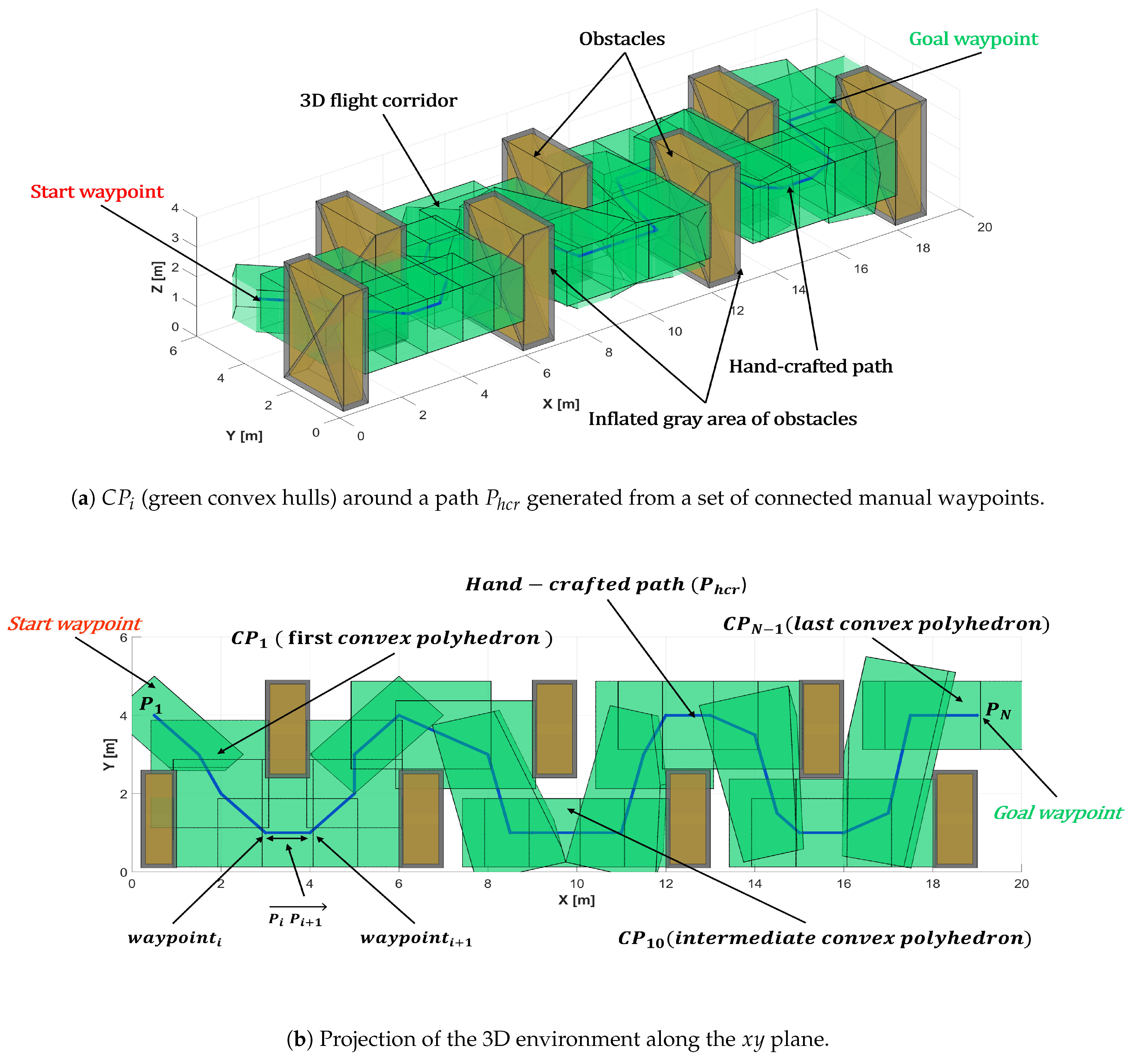
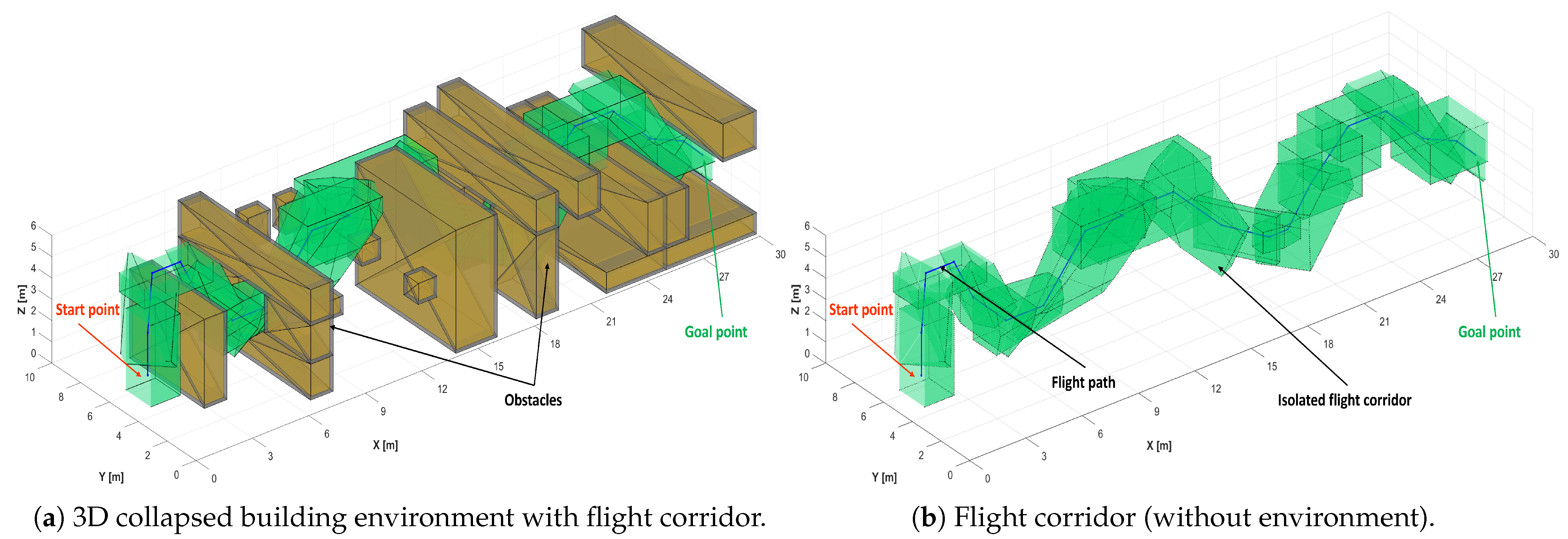
3. Novel 3D Flight Corridor Generation
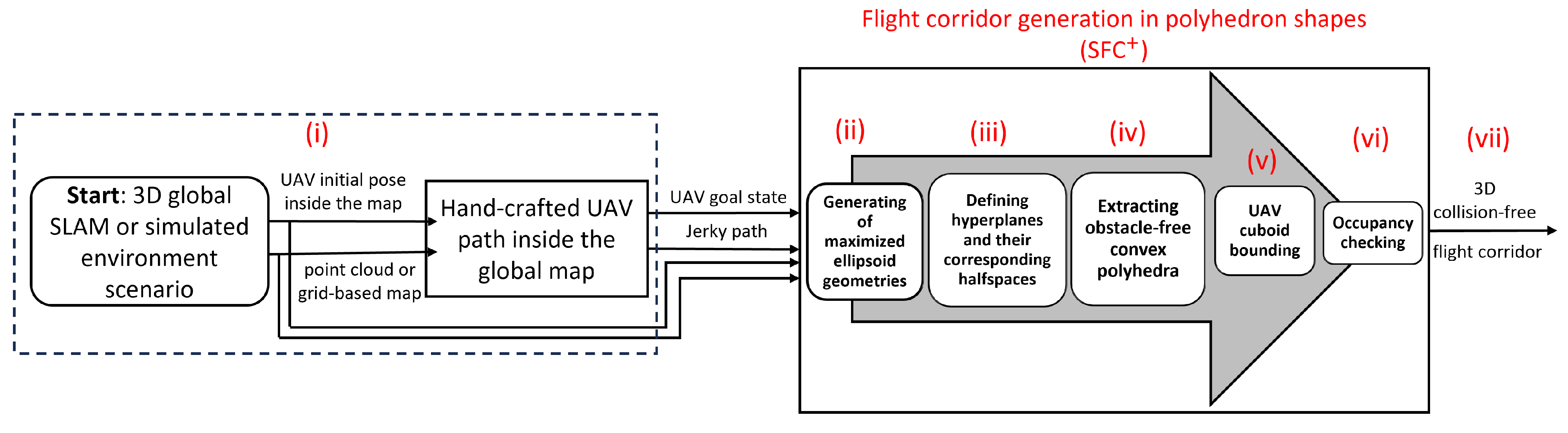
- (i)
- Given an environmental map, generate a hand-crafted flight path composed of multiple path segments.
- (ii)
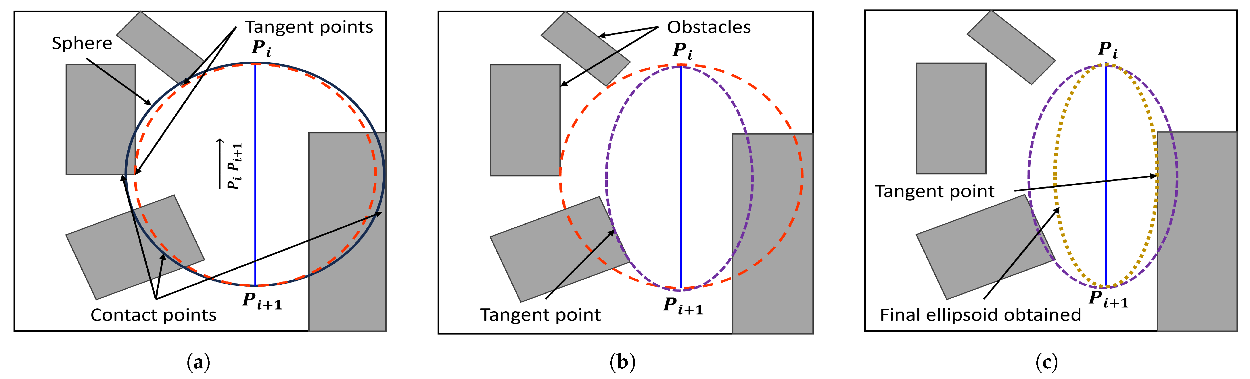
- Generate suitable maximized ellipsoid geometries containing the hand-crafted path segments while avoiding obstacles.
- (iii)
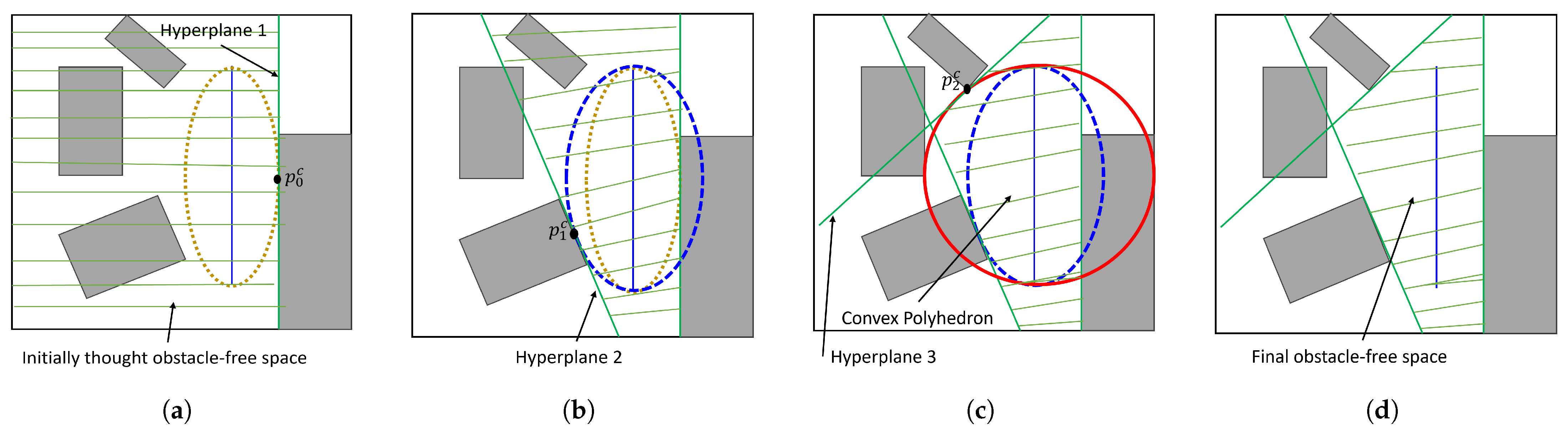
- Define a set of hyperplanes for each path segment and their corresponding halfspaces based on the generated ellipsoids.
- (iv)
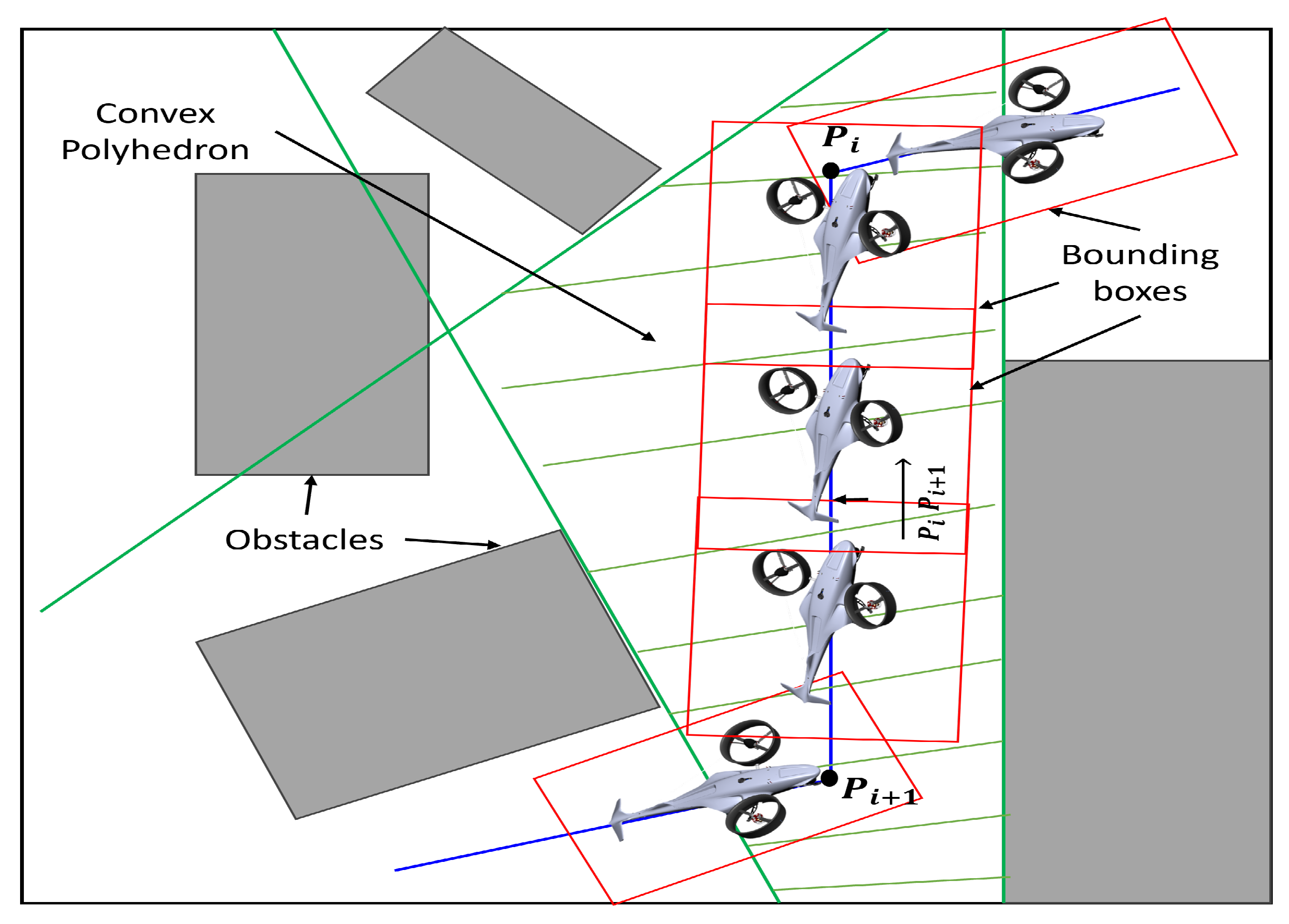
- Extract the intersection of the hyperplanes obtained from step (iii) as obstacle-free convex polyhedra surrounding each segment of the path.
- (v)
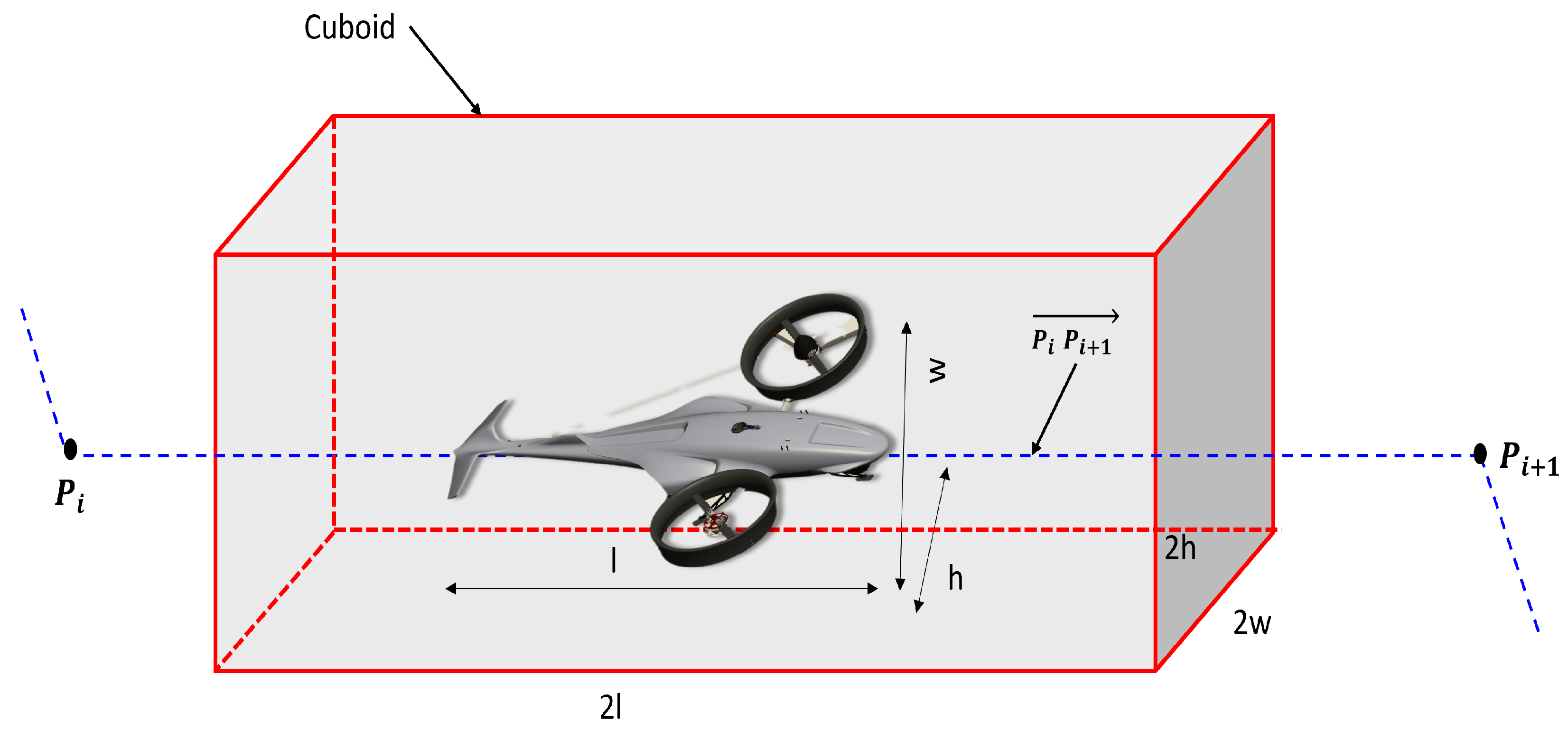
- Perform a cuboid bounding surrounding the UAV based on its dimensions to reduce the number of collision checks required during the polyhedra construction process (step (vi)).
- (vi)
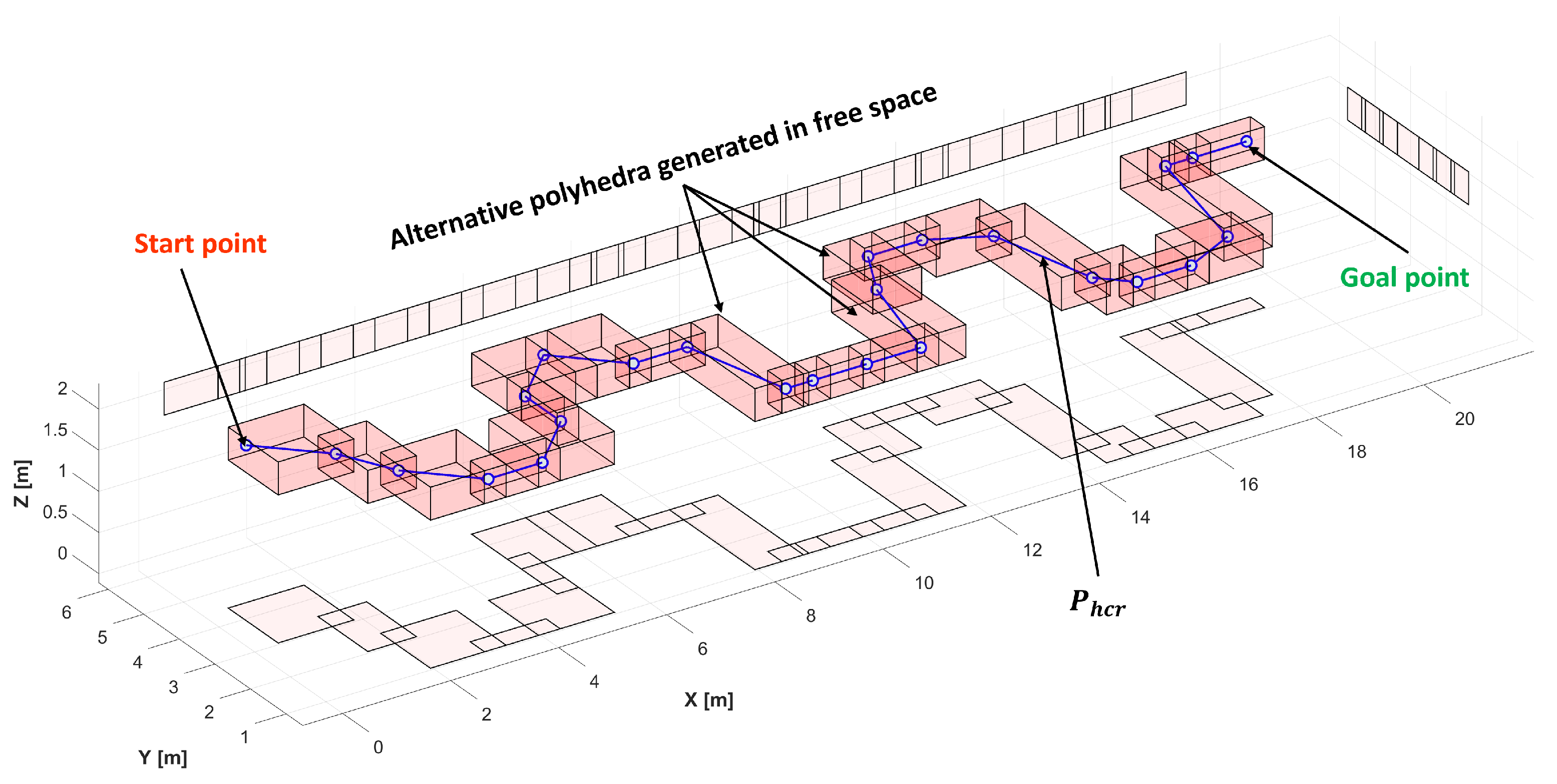
- Add an augmenting occupancy checking process to reduce the search space by identifying regions free from obstacles and replace the previously constructed convex polyhedra with alternate reduced-in-volume convex polyhedra.
- (vii)
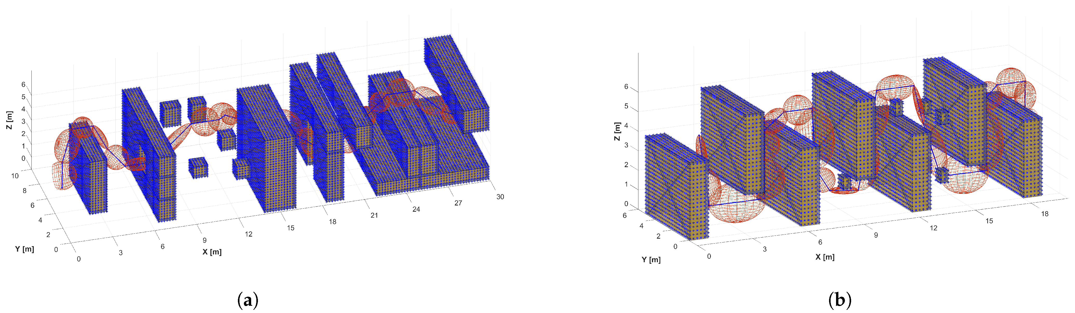
- Generate the 3D Collision-Free Safe Flight Corridor.
3.1. Generation of Convex Polyhedra
3.1.1. Generation of Ellipsoids
| Algorithm 1: Pseudo-code of the proposed SFC flight corridor generation process. |
 |
3.1.2. Intersection of Hyperplanes
3.1.3. Cuboid Bounding
3.1.4. Occupancy Checking
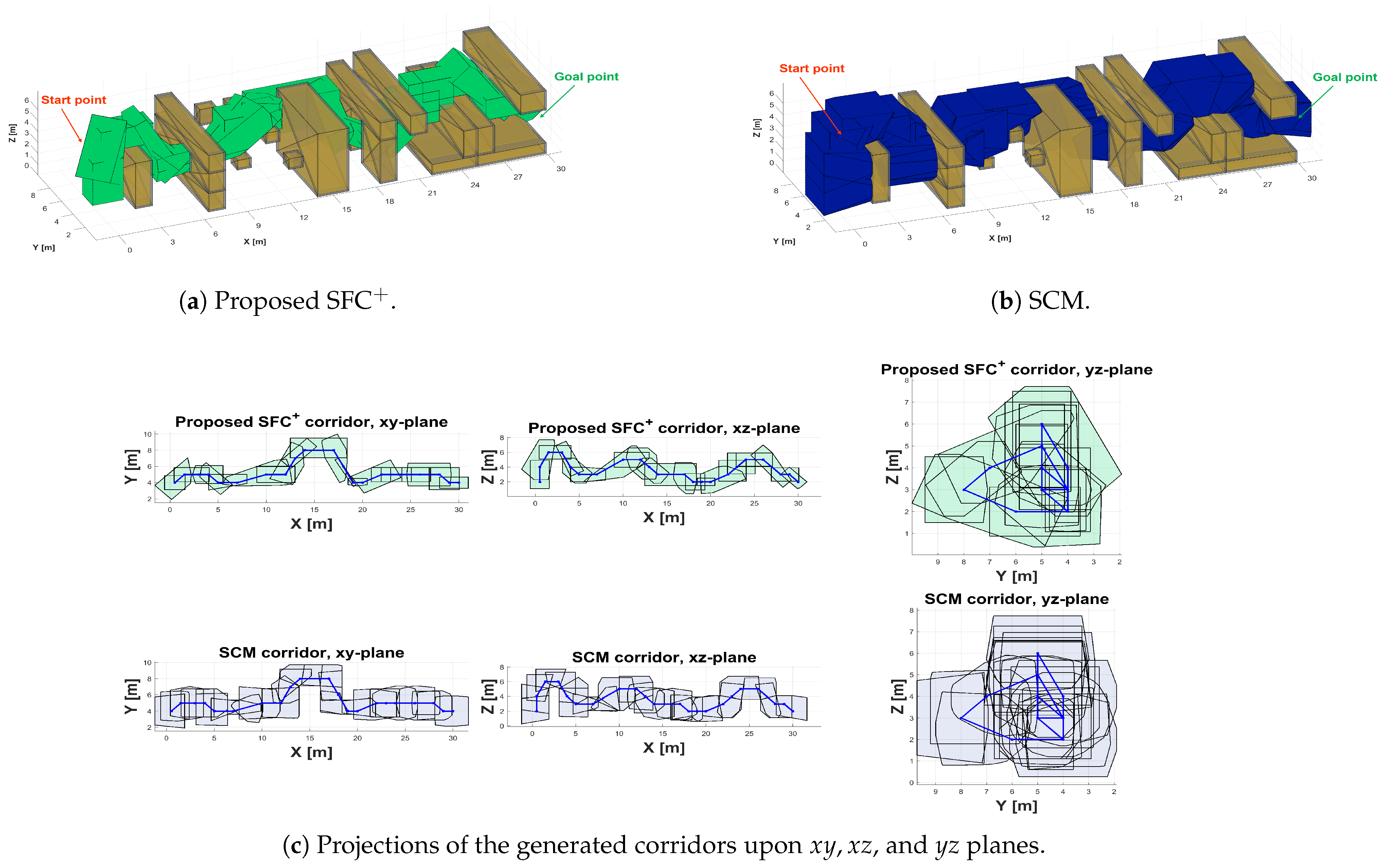
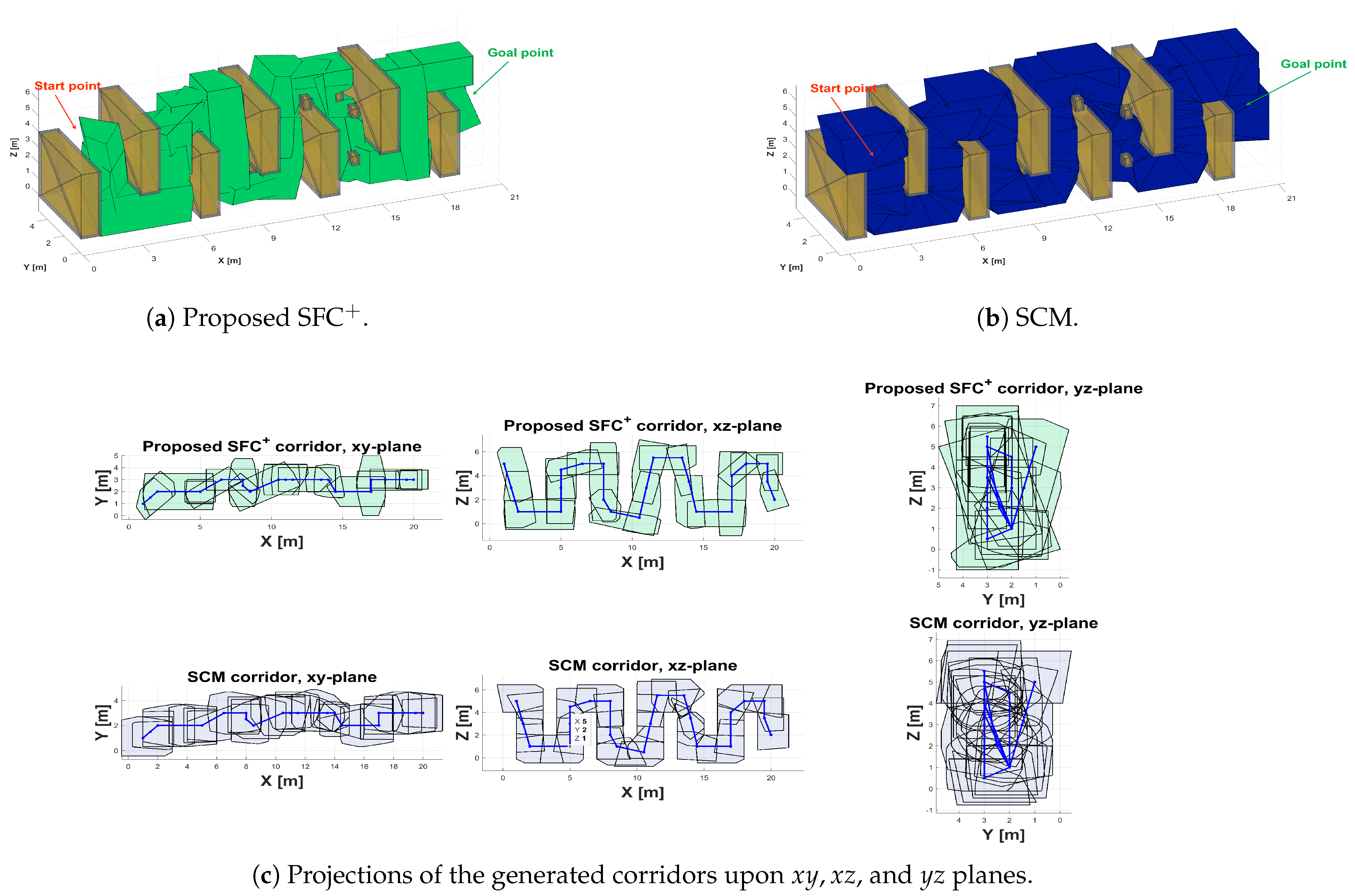
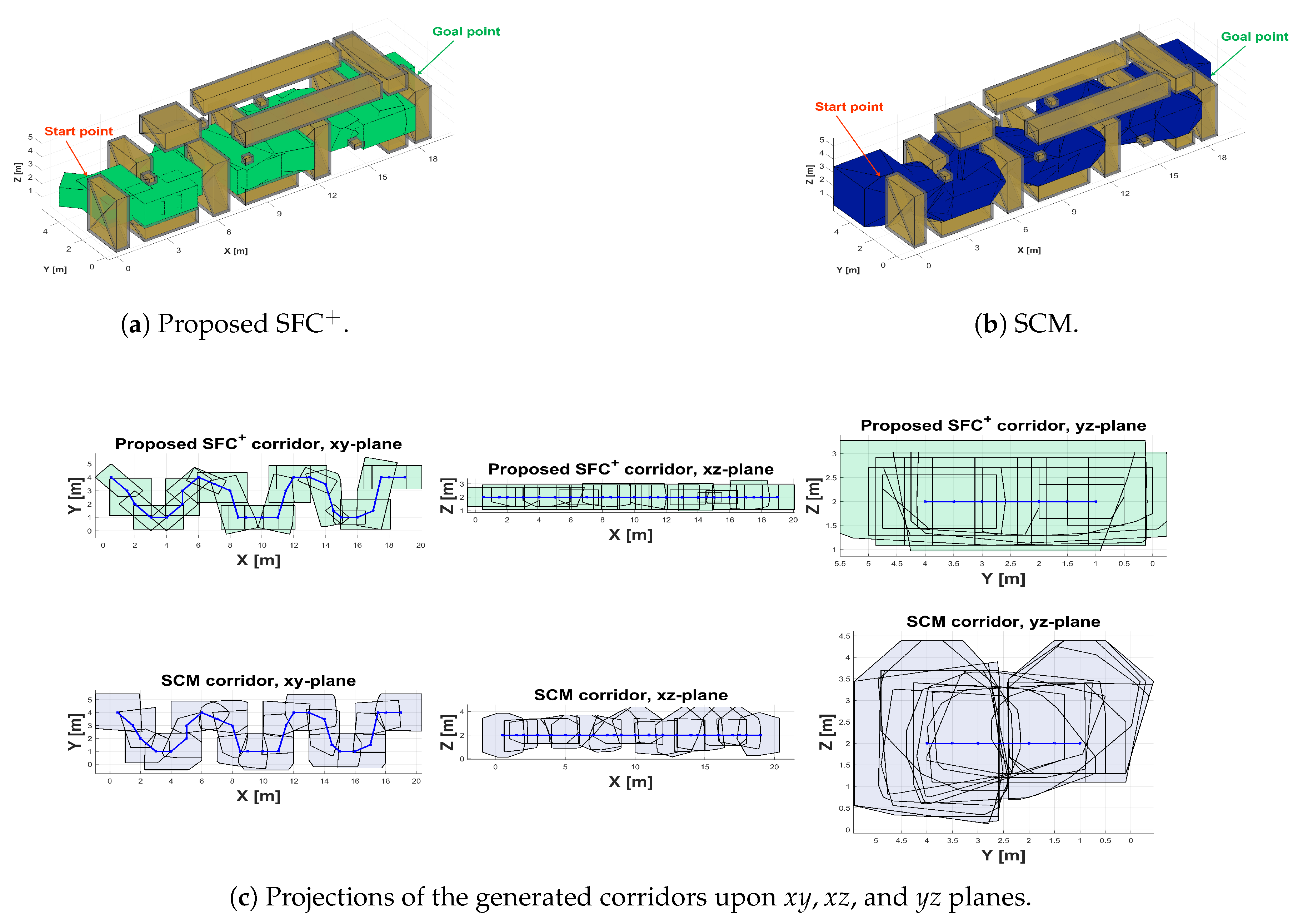
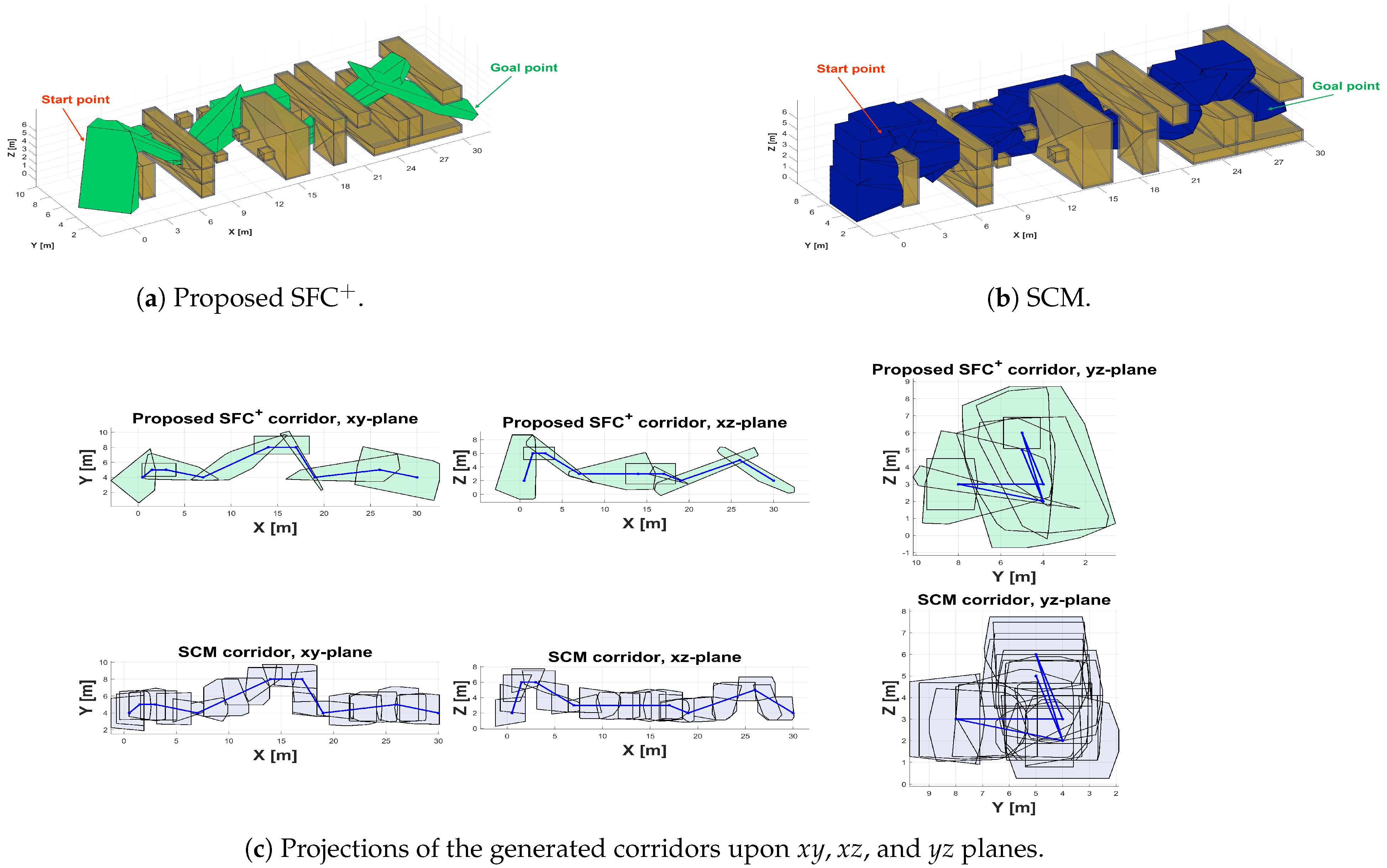
3.1.5. Final Flight Corridor
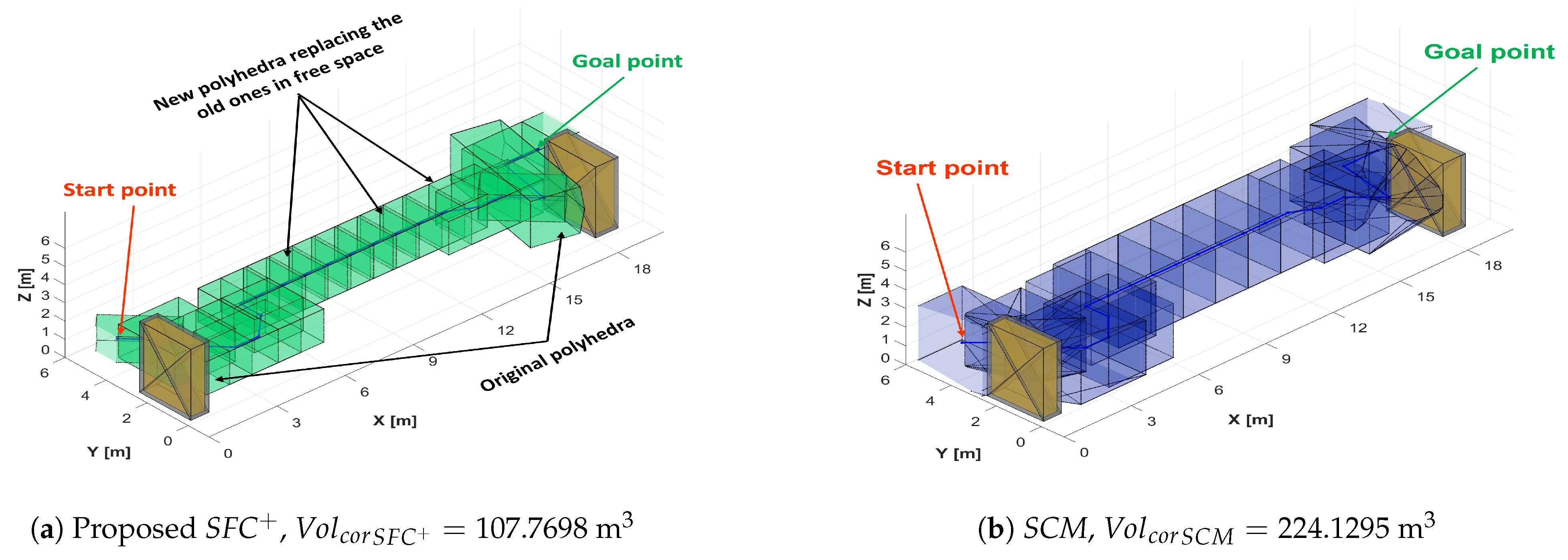
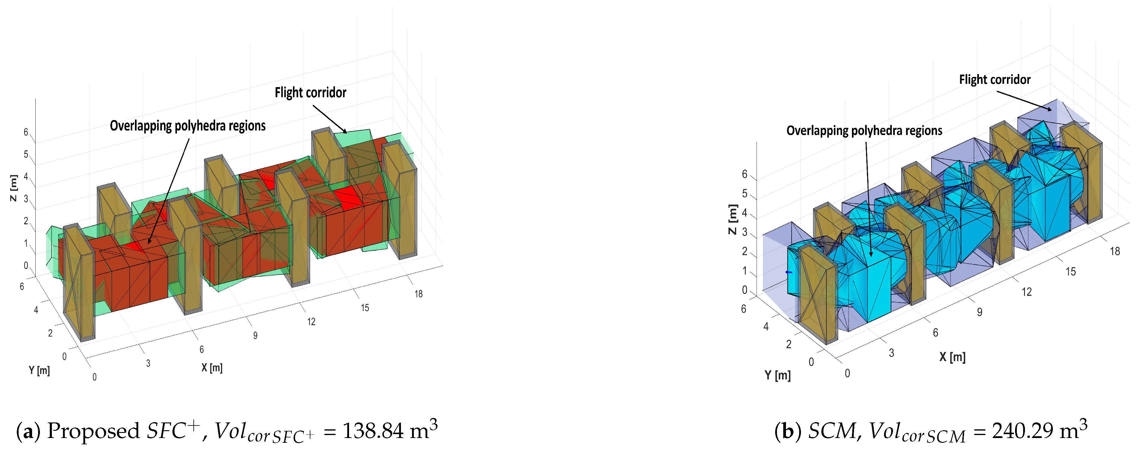
3.2. Calculation of Corridor Volume
4. Simulation Results and Discussion
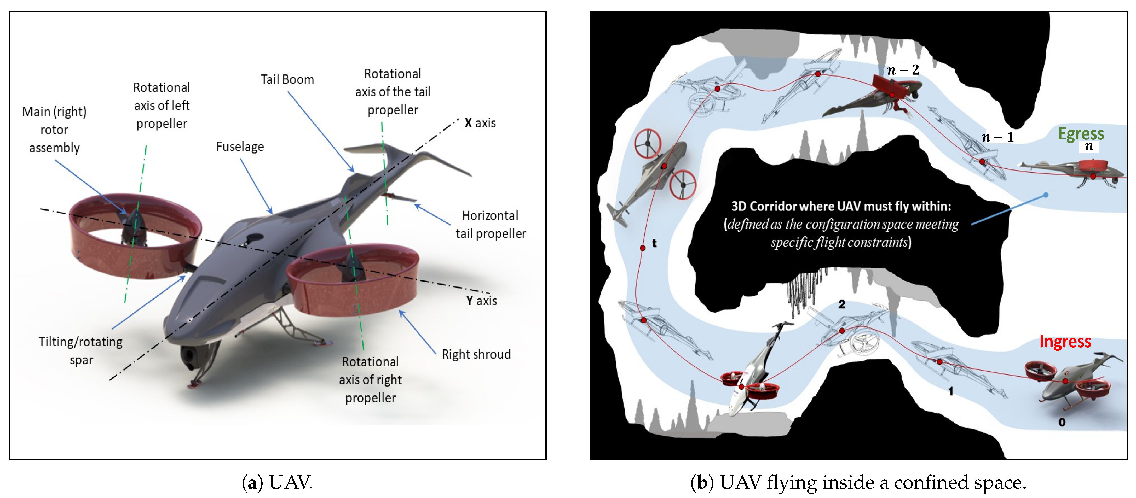
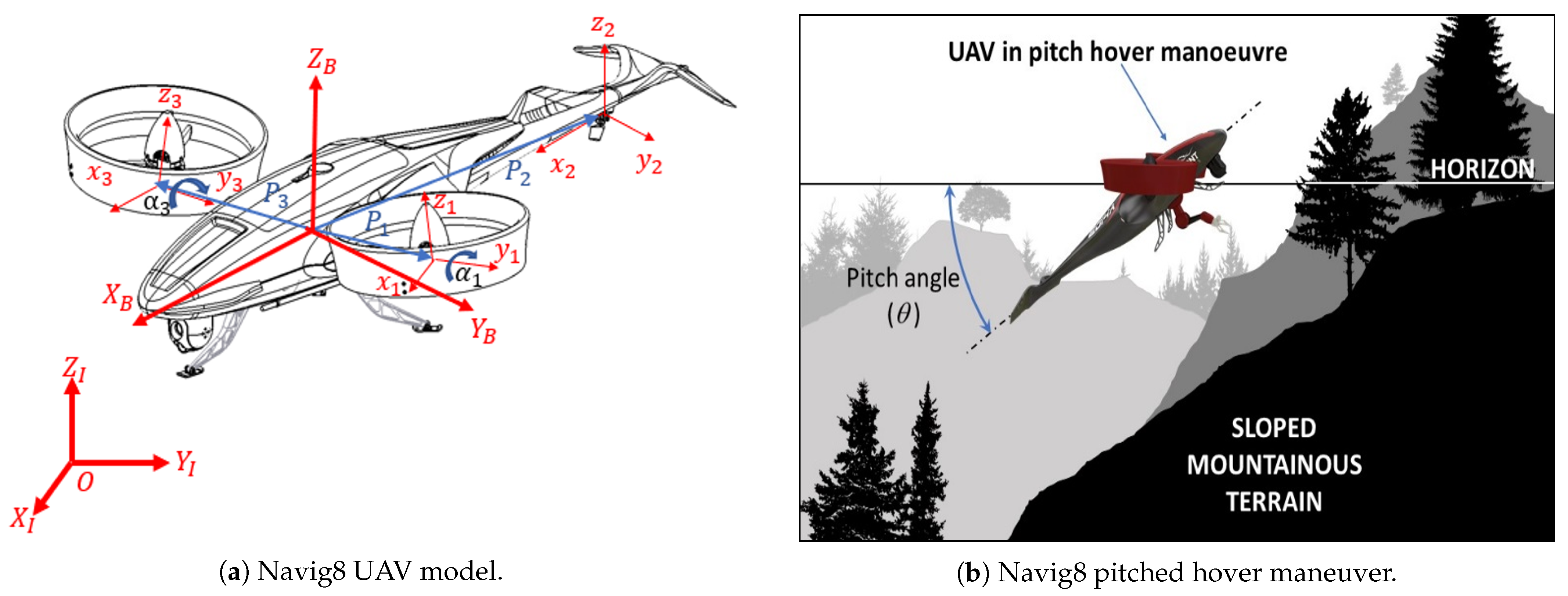
4.1. Selected UAV
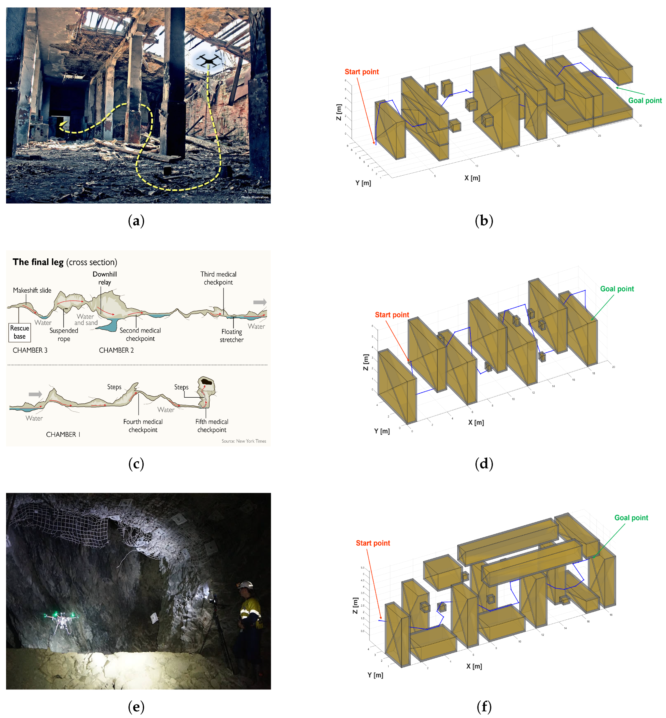
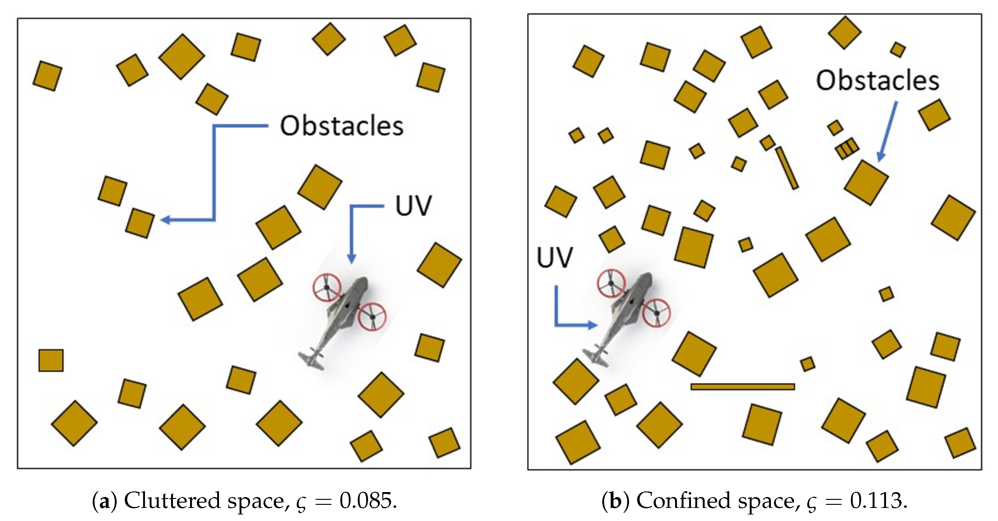
4.2. Testing Scenarios
5. Conclusions
Author Contributions
Funding
Data Availability Statement
Conflicts of Interest
Abbreviations
| CP | Convex Polyhedron |
| IRIS | Iterative Regional Inflation by Semi-Definite Programming |
| I-TRP | Improved “Teach-Repeat-Replan” |
| SCM | Star Convex Method |
| SFC | Enhanced Safe Flight Corridor |
| SLAM | Simultaneous Localization and Mapping |
| UAV | Unmanned Aerial Vehicle |
| USAR | Urban Search and Rescue |
| VTOL | Vertical Take-off and Landing |
References
- Shahmoradi, J.; Talebi, E.; Roghanchi, P.; Hassanalian, M. A comprehensive review of applications of drone technology in the mining industry. Drones 2020, 4, 34. [Google Scholar] [CrossRef]
- Ren, H.; Zhao, Y.; Xiao, W.; Hu, Z. A review of UAV monitoring in mining areas: Current status and future perspectives. Int. J. Coal Sci. Technol. 2019, 6, 320–333. [Google Scholar] [CrossRef]
- Półka, M.; Ptak, S.; Kuziora, Ł. The use of UAV’s for search and rescue operations. Procedia Eng. 2017, 192, 748–752. [Google Scholar] [CrossRef]
- Neubauer, M.; Günther, G.; Füllhas, K. Structural Design Aspects and Criteria for Military UAV; Technical Report; European Aeronautic Defence and Space (EADS): Munich, Germany, 2007. [Google Scholar]
- Gupta, S.G.; Ghonge, D.M.; Jawandhiya, P.M. Review of unmanned aircraft system (UAS). Int. J. Adv. Res. Comput. Eng. Technol. (IJARCET) 2013, 2, 1646–1658. [Google Scholar] [CrossRef]
- Innocente, M.S.; Grasso, P. Self-organising swarms of firefighting drones: Harnessing the power of collective intelligence in decentralised multi-robot systems. J. Comput. Sci. 2019, 34, 80–101. [Google Scholar] [CrossRef]
- CSIRO Head Office; Westwick-Farrow Pty Ltd. Researchers Deploy Autonomous Drone to Improve Operations for Mining Industry. November 2017. Available online: https://www.processonline.com.au/content/business/news/researchers-deploy-autonomous-drone-to-improve-operations-for-mining-industry-1267356273 (accessed on 24 September 2023).
- Coldewey, D. Subterranean Drone Mapping Startup Emesent Raises $2.5 M to Autonomously Delve the Deep. TechCrunch; November 2018. Available online: https://techcrunch.com/2018/11/05/subterranean-drone-mapping-startup-emesent-raises-2-5m-to-autonomously-delve-the-deep/ (accessed on 24 September 2023).
- Reporter, S. Mapping the Underground with Drones, Legged Robots. Aspermont Media Ltd. October 2018. Available online: https://www.miningmagazine.com/innovation/news/1347934/mapping-the-underground-with-drones-legged-robots (accessed on 24 September 2023).
- Liang, H.; Lee, S.C.; Bae, W.; Kim, J.; Seo, S. Towards UAVs in Construction: Advancements, Challenges, and Future Directions for Monitoring and Inspection. Drones 2023, 7, 202. [Google Scholar] [CrossRef]
- Liu, S.; Watterson, M.; Mohta, K.; Sun, K.; Bhattacharya, S.; Taylor, C.J.; Kumar, V. Planning dynamically feasible trajectories for quadrotors using safe flight corridors in 3-d complex environments. IEEE Robot. Autom. Lett. 2017, 2, 1688–1695. [Google Scholar] [CrossRef]
- Zinage, V.; Arul, S.H.; Manocha, D.; Ghosh, S. 3D-Online Generalized Sensed Shape Expansion: A Probabilistically Complete Motion Planner in Obstacle-Cluttered Unknown Environments. IEEE Robot. Autom. Lett. 2023, 8, 3334–3341. [Google Scholar] [CrossRef]
- Chen, J.; Liu, T.; Shen, S. Online generation of collision-free trajectories for quadrotor flight in unknown cluttered environments. In Proceedings of the 2016 IEEE International Conference on Robotics and Automation (ICRA), Stockholm, Sweden, 16–21 May 2016; pp. 1476–1483. [Google Scholar]
- Gao, F.; Wang, L.; Zhou, B.; Zhou, X.; Pan, J.; Shen, S. Teach-repeat-replan: A complete and robust system for aggressive flight in complex environments. IEEE Trans. Robot. 2020, 36, 1526–1545. [Google Scholar] [CrossRef]
- Gao, F.; Wang, L.; Wang, K.; Wu, W.; Zhou, B.; Han, L.; Shen, S. Optimal trajectory generation for quadrotor teach-and-repeat. IEEE Robot. Autom. Lett. 2019, 4, 1493–1500. [Google Scholar] [CrossRef]
- Lien, J.M.; Amato, N.M. Approximate convex decomposition of polygons. In Proceedings of the Twentieth Annual Symposium on Computational Geometry, Brooklyn, NY, USA, 9–11 June 2004; pp. 17–26. [Google Scholar]
- Liu, H.; Liu, W.; Latecki, L.J. Convex shape decomposition. In Proceedings of the 2010 IEEE Computer Society Conference on Computer Vision and Pattern Recognition, San Francisco, CA, USA, 13–18 June 2010; pp. 97–104. [Google Scholar]
- Eidenbenz, S.J.; Widmayer, P. An approximation algorithm for minimum convex cover with logarithmic performance guarantee. SIAM J. Comput. 2003, 32, 654–670. [Google Scholar] [CrossRef]
- Feng, H.Y.; Pavlidis, T. Decomposition of polygons into simpler components: Feature generation for syntactic pattern recognition. IEEE Trans. Comput. 1975, 100, 636–650. [Google Scholar] [CrossRef]
- Deits, R.; Tedrake, R. Computing large convex regions of obstacle-free space through semidefinite programming. In Proceedings of the Algorithmic Foundations of Robotics XI: Selected Contributions of the Eleventh International Workshop on the Algorithmic Foundations of Robotics, Istanbul, Turkey, 3–5 August 2015; pp. 109–124. [Google Scholar]
- Deits, R.; Tedrake, R. Efficient mixed-integer planning for UAVs in cluttered environments. In Proceedings of the 2015 IEEE International Conference on Robotics and Automation (ICRA), Washington, DC, USA, 26–30 May 2015; pp. 42–49. [Google Scholar]
- Tan, L.; Hu, M.; Lin, H. Agent-based simulation of building evacuation: Combining human behavior with predictable spatial accessibility in a fire emergency. Inf. Sci. 2015, 295, 53–66. [Google Scholar] [CrossRef]
- Mamou, K.; Ghorbel, F. A simple and efficient approach for 3D mesh approximate convex decomposition. In Proceedings of the 2009 16th IEEE International Conference on Image Processing (ICIP), Cairo, Egypt, 7–10 November 2009; pp. 3501–3504. [Google Scholar]
- Sarmientoy, A.; Murrieta-Cidz, R.; Hutchinsony, S. A sample-based convex cover for rapidly finding an object in a 3-D environment. In Proceedings of the 2005 IEEE International Conference on Robotics and Automation, Barcelona, Spain, 18–22 April 2005; pp. 3486–3491. [Google Scholar]
- Savin, S. An algorithm for generating convex obstacle-free regions based on stereographic projection. In Proceedings of the 2017 International Siberian Conference on Control and Communications (SIBCON), Astana, Kazakhstan, 29–30 June 2017; pp. 1–6. [Google Scholar]
- Zhong, X.; Wu, Y.; Wang, D.; Wang, Q.; Xu, C.; Gao, F. Generating large convex polytopes directly on point clouds. arXiv 2020, arXiv:2010.08744. [Google Scholar]
- Jansen, F.; Ramirez-Serrano, A. Extended MPC Strategy for Maneuvering Unmanned Vehicles in Restricted 3D Environments. In Proceedings of the Unmanned Systems Canada Conference, Montreal, QC, Canada, 12 November 2011. [Google Scholar]
- Hosseini, Z.; Ramirez-Serrano, A.; Martinuzzi, R.J. Ground/wall effects on a tilting ducted fan. Int. J. Micro Air Veh. 2011, 3, 119–141. [Google Scholar] [CrossRef]
- Jansen, F. Manoeuvring Unmanned Vehicles through Confined 3D Environments Using Model Predictive Control. Master’s Thesis, University of Calgary, Calgary, AB, Canada, 2011. [Google Scholar]
- Lay, S.R. Convex Sets and Their Applications; Courier Corporation: Chelmsford, MA, USA, 2007. [Google Scholar]
- Boyd, S.P.; Vandenberghe, L. Convex Optimization; Cambridge University Press: Cambridge, UK, 2004. [Google Scholar]
- Cherney, M. Drones Are Now Operating Underground: Mining Companies Look to Automation to Help Companies Dig Out More Ore and Save Lives. Kathryn Report Company. November 2017. Available online: http://www.kathrynsreport.com/2017/11/drones-are-now-operating-underground.html (accessed on 24 September 2023).
- Hannah Beech, R.C.P.; Suhartono, M. Still Can’t Believe It Worked’: The Story of the Thailand Cave Rescue. The New York Times, 12 July 2018. [Google Scholar]


| Environment | Obstacle Density () | No. of Obstacles | Overall Size of the Space (w × h × d, m) | Coordinates of Entry Point (m) | Coordinates of Exit Points (m) |
|---|---|---|---|---|---|
| Collapsed building | (confined space) | 20 | 30 × 10 × 6 | [0.5,4,2] | [30,4,2] |
(confined space) | 10 | ||||
(cluttered space) | 9 | ||||
| Steep cave | (confined space) | 14 | 20 × 5 × 6 | [1,1,5] | [20,3,2] |
(confined space) | 5 | ||||
(cluttered space) | 3 | ||||
| Obstructed mine corridor | (confined space) | 21 | 20 × 5 × 6 | [0.5,4,2] | [19,4,2] |
(confined space) | 19 | ||||
(cluttered space) | 17 |
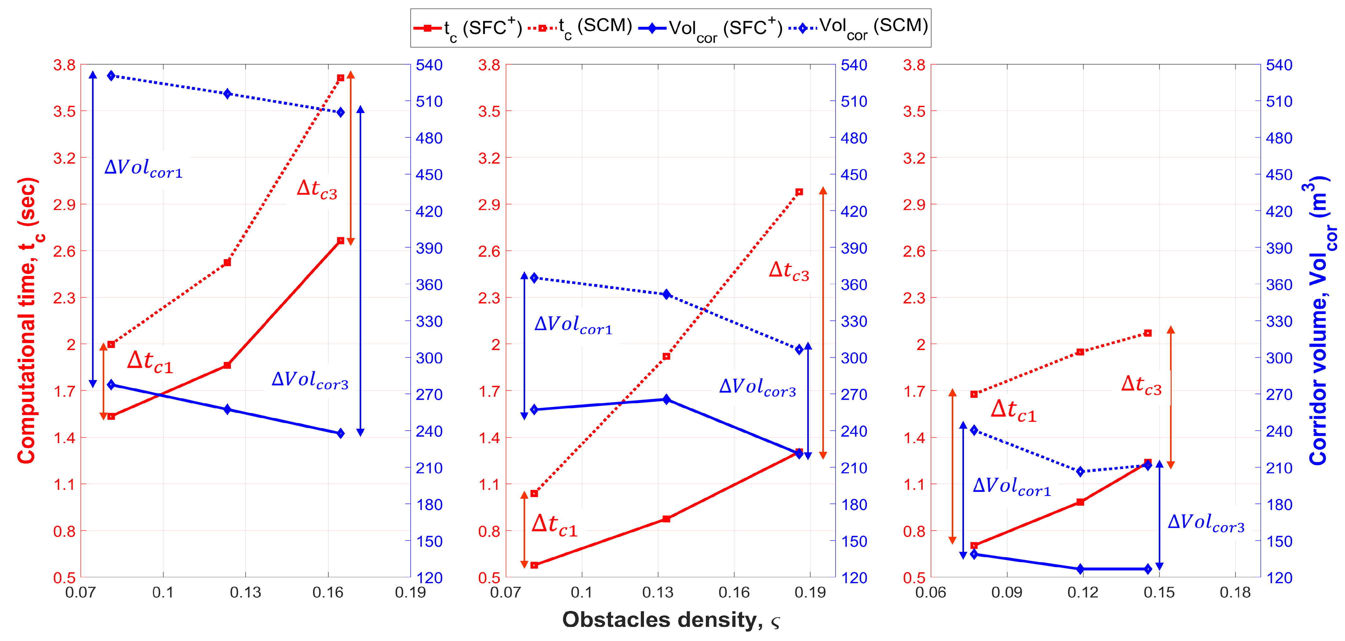
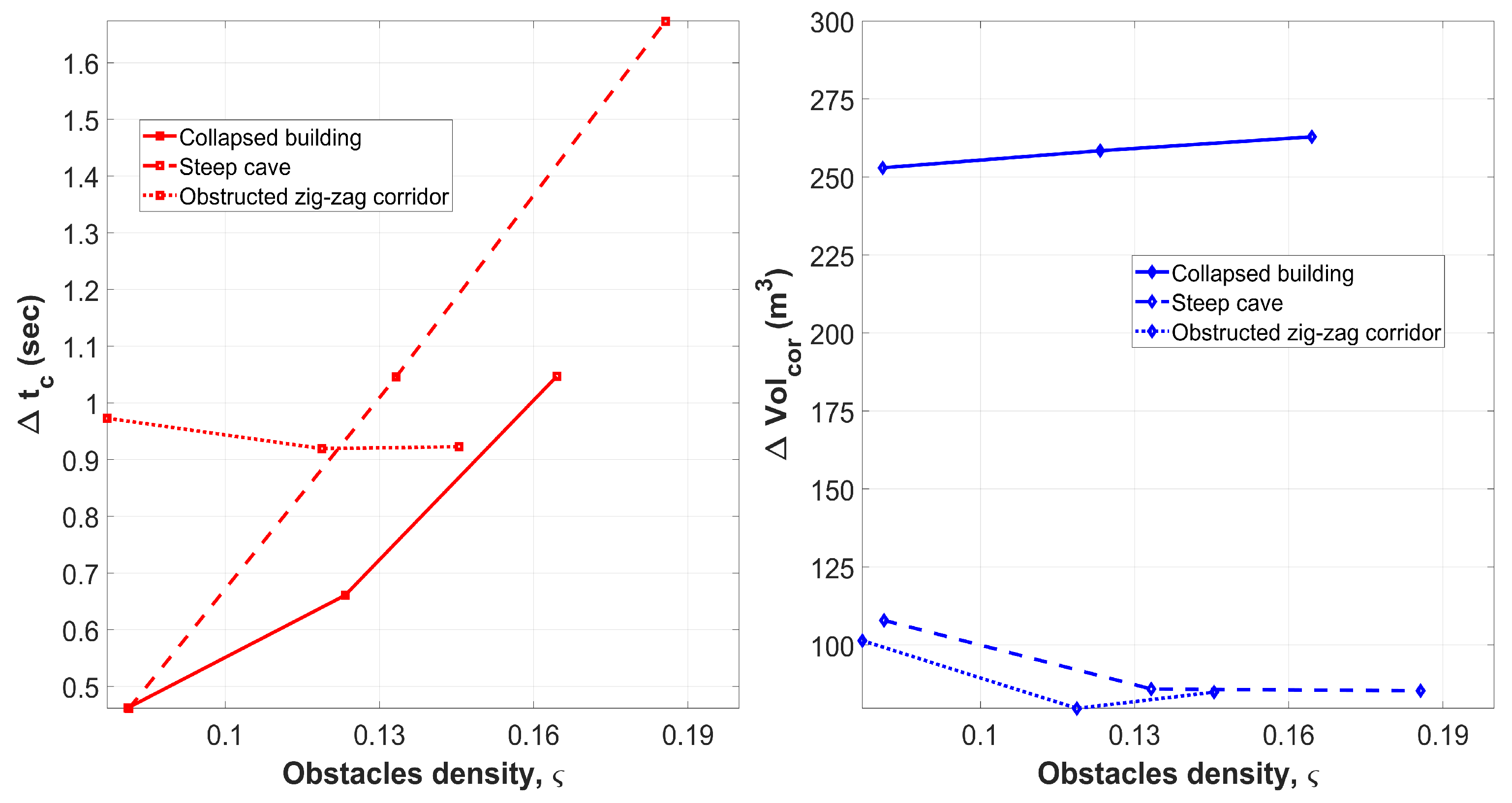
| Computational Time (, s) | Corridor Volume (m3) | No. of Generated Polyhedra | ||||||
|---|---|---|---|---|---|---|---|---|
| Obstacle Density () | Map Resolution (Voxel Size, ) | Proposed SFC | SCM | Proposed SFC | SCM | Proposed SFC | SCM | |
| Collapsed building map scenario | 2.5818 | 3.5284 | 237.6235 | 500.5325 | 21 | 27 | ||
| 2.6651 | 3.712 | 237.6235 | 500.5325 | 21 | 27 | |||
| 1.8453 | 2.5013 | 257.3771 | 515.8238 | 21 | 25 | |||
| 1.862 | 2.5227 | 257.3771 | 515.8238 | 21 | 25 | |||
| 1.5007 | 2.0604 | 277.559 | 530.5415 | 21 | 24 | |||
| 1.5351 | 1.9972 | 277.559 | 530.5415 | 21 | 24 | |||
| Cave map scenario | 1.3274 | 2.8754 | 221.0281 | 306.3768 | 21 | 33 | ||
| 1.3054 | 2.9787 | 221.0281 | 306.3768 | 21 | 33 | |||
| 0.90729 | 1.9332 | 265.5472 | 351.4842 | 21 | 28 | |||
| 0.87448 | 1.9204 | 265.5472 | 351.4842 | 21 | 28 | |||
| 0.62353 | 1.0092 | 257.136 | 365.0643 | 21 | 27 | |||
| 0.5778 | 1.0391 | 257.136 | 365.0643 | 21 | 27 | |||
| Obstructed mining map scenario | 1.196 | 2.0492 | 126.6911 | 211.6088 | 24 | 18 | ||
| 1.1476 | 2.0704 | 126.6911 | 211.6088 | 24 | 18 | |||
| 1.1009 | 1.9819 | 126.6911 | 206.3995 | 24 | 19 | |||
| 1.0287 | 1.9481 | 126.6911 | 206.3995 | 24 | 19 | |||
| 0.71836 | 1.5541 | 138.8408 | 240.288 | 24 | 19 | |||
| 0.70418 | 1.6772 | 138.8408 | 240.288 | 24 | 19 | |||
| Computational Time (, s) | Corridor Volume (m3) | No. of Generated Polyhedra | ||||||
|---|---|---|---|---|---|---|---|---|
| Obstacle Density () | Map Resolution (Voxel Size, cm) | Proposed SFC | SCM | Proposed SFC | SCM | Proposed SFC | SCM | |
| Collapsed building map scenario | 2.1929 | 2.7444 | 231.7023 | 358.8962 | 7 | 24 | ||
| 1.9182 | 2.9326 | 309.0498 | 423.968 | 8 | 23 | |||
| Cave map scenario | 1.0666 | 2.7866 | 370.3862 | 307.041 | 13 | 32 | ||
| 1.0577 | 2.6848 | 362.4562 | 288.697 | 13 | 30 | |||
| Obstructed mining environment | 0.66375 | 1.806 | 113.088 | 177.5656 | 7 | 18 | ||
| 0.70554 | 1.6912 | 93.0473 | 172.254 | 6 | 19 | |||
Disclaimer/Publisher’s Note: The statements, opinions and data contained in all publications are solely those of the individual author(s) and contributor(s) and not of MDPI and/or the editor(s). MDPI and/or the editor(s) disclaim responsibility for any injury to people or property resulting from any ideas, methods, instructions or products referred to in the content. |
© 2023 by the authors. Licensee MDPI, Basel, Switzerland. This article is an open access article distributed under the terms and conditions of the Creative Commons Attribution (CC BY) license (https://creativecommons.org/licenses/by/4.0/).
Share and Cite
Mostafa, S.; Ramirez-Serrano, A. Three-Dimensional Flight Corridor: An Occupancy Checking Process for Unmanned Aerial Vehicle Motion Planning inside Confined Spaces. Robotics 2023, 12, 134. https://doi.org/10.3390/robotics12050134
Mostafa S, Ramirez-Serrano A. Three-Dimensional Flight Corridor: An Occupancy Checking Process for Unmanned Aerial Vehicle Motion Planning inside Confined Spaces. Robotics. 2023; 12(5):134. https://doi.org/10.3390/robotics12050134
Chicago/Turabian StyleMostafa, Sherif, and Alejandro Ramirez-Serrano. 2023. "Three-Dimensional Flight Corridor: An Occupancy Checking Process for Unmanned Aerial Vehicle Motion Planning inside Confined Spaces" Robotics 12, no. 5: 134. https://doi.org/10.3390/robotics12050134