1. Introduction
Autonomous robotic systems are increasingly appearing in our daily lives. These include domestic robots, such as those used in care settings [
1], as well as industrial robots used in, for example, the monitoring of assets in hazardous environments [
2]. The benefits of autonomous robots in these settings cannot be understated. In the domestic case, they provide assistance to humans that may not have had help otherwise. In hazardous environments, the use of such systems allows us to automate potentially dangerous tasks that would have otherwise had to be carried out directly by humans. Even though the use of robotics can be massively rewarding, humans are naturally and correctly cautious of the decisions that these systems can make. Therefore to examine and strengthen our confidence that these systems work correctly, robust verification methods are needed.
Robotics lies at the intersection of multi-component software systems and sophisticated real-world machinery that is designed to carry out important tasks often with minimal human supervision. These hybrid safety- and/or mission-critical systems require a high level of confidence in their design and specifications, in some domains even needing official certification such as in the nuclear sector [
3]. To achieve a high level of confidence, verification techniques beyond, and in combination with, standard software testing are required [
4]. This kind of robust verification often involves the use of formal methods alongside testing and simulation.
Formal methods are mathematical techniques and software tools that are used to ensure the correctness of programs and software systems. A wide range of formal verification methods are and have been used for autonomous robotic systems [
4,
5,
6]. Robotic systems are large but conveniently modular, making it possible to decompose the formal verification task and focus on particularly critical components, including: autonomous agents [
5], planners [
6], and our previous work on execution plans [
7]—which we expand upon in this paper.
Our work enables the formal verification of execution plans for mobile agents that use Python’s
turtle package through our toolchain: CSP2Turtle. This enables a user to describe the agent’s environment and formally specify a plan for its behaviour, which CSP2Turtle automatically verifies and then produces the Python code to execute the plan. This is one of the formal verification recipes suggested in [
8]. Our chosen formal verification approach is
model-checking, in which a model-checking tool exhaustively examines a model’s state space to determine if a property holds. Our formalism-of-choice for this work, Communicating Sequential Processes (CSP) [
9], enables the specification of complex behaviour and is supported by automatic model-checking tools. Various other formal approaches have been used in the literature to specify and verify (often autonomous) robotic systems, including static analysis, abstract interpretation, theorem proving, formal specification, and so on. For a survey of the state-of-the-art in applying formal methods to autonomous robots, see [
4].
We use the Python
Turtle package as an abstraction of more complex mobile agents so that we can explore the utility of CSP as a specification language for robotic execution plans. A mobile robotic agent executing a plan is common to many applications ranging from domestic assistants to space exploration. For example, an autonomous rover could be tasked with monitoring infrastructure or taking measurements at specific locations in a predefined operating area [
5,
6]. The rover must accurately and correctly execute a plan to navigate from its current
start position to its next
goal position. If this execution plan asks for something impossible because it does not align with the physical reality of the robot’s environment, or if it asks for something logically contradictory, then the corresponding plan is incorrect. Incorrect plans result in erroneous and even unpredictable robot behaviour. Analysing the correctness of these execution plans can be difficult and time-consuming using classical testing methods alone. In particular, running simulations can be protracted, and physical tests may be risky and infeasible. Checking the execution plan against the robot’s specifications and relevant properties of its environment during the design phase would avoid producing incorrect plans and avoid overheads associated with a design loop of producing a plan, running it on the robot, and seeing how the robot performs.
Our previous work provided an initial description of our CSP2Turtle tool chain [
7], which we illustrated via a case study verifying execution plans for turtle robots. In this way, we verified the properties about execution plans, specified using the CSP process algebra and the FDR model-checker. In this paper, we extend our prior work [
7]. Specifically, we have further developed our approach and case study in the following ways:
The capabilities of the planning language have been increased by allowing execution plans to make use of the CSP choice operator (
Section 4.2).
The starting location of the turtle is adjustable (see
Section 5). In our previous paper [
7], this was a fixed location.
The toolchain produces a valid plan via a search of the model (
Section 4).
An option has been introduced to read plan specifications from files, allowing for more flexible use and testing (
Section 4).
The scalability of the toolchain over various parameters has been tested (
Section 7).
Further, this paper provides more detailed usage examples, a more comprehensive account of related work and a discussion section where we explore how our CSP2Turtle toolchain can be used more broadly.
The remainder of this paper is structured as follows: in
Section 2, we provide an overview of
Turtle and CSP, as well as related research. Note that we use
Turtle to indicate the package or software and “turtle” to indicate the agent. Next,
Section 3 describes our approach to modelling
Turtle in CSP. In
Section 4, we further describe the toolchain that was leveraged for verification and code synthesis. We illustrate our approach and usability via examples in
Section 5. We evaluate CSP2Turtle in terms of the choice of verification tools and usability in
Section 7. In
Section 8, we discuss the broader context of the toolchain, with references to other uses, including formal methods of education. Finally,
Section 9 concludes the paper and identifies future research directions.
2. Background and Related Work
This section provides the reader with prerequisite information about Python’s
Turtle package (
Section 2.1) and the CSP process algebra (
Section 2.2). As previously mentioned, CSP enables the specification of complex system behaviour, which ranges from simple sequences of behaviour to more intricate interleavings of actions. Our work uses CSP to model the core behaviour of the
Turtle package and to enable a user of our CSP2Turtle toolchain to specify an execution plan for the turtle agent. Finally, we provide an overview of related work (
Section 2.3), where we distinguish our work from research in this area.
2.1. The Turtle Package
Turtle is a graphics package in the standard Python distribution (
https://docs.python.org/3/library/turtle.html, accessed on 19 January 2023). This package allows a user to control an agent (the “turtle”) on a 2D plane (the “canvas”). The user controls the turtle either by writing a script or interactively from the command prompt. The user moves the turtle around and controls a “pen” that draws a line when the pen is “down” (i.e., in contact with the canvas). A certain amount of the canvas is visible to the user on the screen, but the turtle can move and draw outside this too. This allows for immediate visual feedback that shows the live progress of the turtle. It is based on the Logo programming language, which has been used to program physical turtle robots (
https://web.archive.org/web/20150131192445/https://el.media.mit.edu/logo-foundation/logo/turtle.html, accessed on 19 January 2023) and provides a Logo-like set of commands via Python methods. The turtle only operates in a 2D world and cannot be used to create 3D dimensional objects.
Running a
Turtle program produces a visual display of the turtle following the plan of these commands, tracing a line behind it when the pen is down.
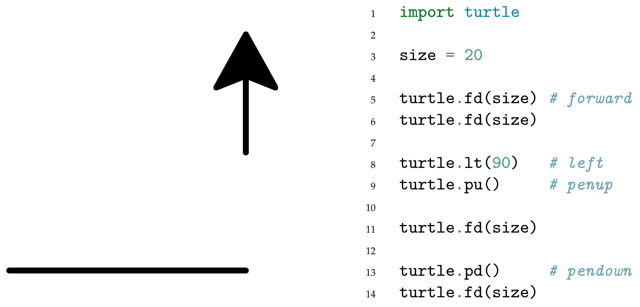
Figure 1 shows a typical simple
Turtle program, which illustrates all the basic functionality we explore in this paper. The turtle traced its path on the canvas as it moved around and produced the graphical output shown in the process. The turtle starts at (0, 0), facing to the right (east), with the pen down. The location of the turtle is indicated by the arrowhead, and the direction it is facing is indicated by the point of the arrow. After executing all the commands, the turtle in
Figure 1 is now facing up (north). On lines 5 and 6, it is told to move
size units forward twice. As it starts with the pen down, this results in the horizontal line at the bottom of the figure. Then, on lines 8 and 9, it rotates 90 degrees to the left and lifts the pen up. When it then moves forward in the upward direction, it does not draw, explaining the gap in the line. Finally, on line 13, it puts the pen down again before moving forward a final time on line 14.
The turtle has navigation commands for movement (
forward(), backward()) and changing its direction (
left(), right()); arguments passed to these functions indicate the distance it should move and the angle it should turn, respectively. The turtle also has commands to control the pen to toggle whether or not the turtle draws as it moves along the canvas (
penup(), pendown()). These six commands are the focus of our modelling approach, as described in
Section 3.
The Turtle package has numerous other features that are not the focus of our model. Some of these are cosmetic options, such as pen colour, pen width, turtle shape, etc. There are also additional commands, including leaving a stamp at the turtle’s current location, and the ability to start “recording” the turtle’s movements and draw a polygon along its path when it is finished moving. Our model focuses on what we consider to be the core features of the Turtle package, the basic movements and drawing capabilities, allowing us to explore the utility of enabling users to use CSP to write an execution plan for the turtle to follow.
2.2. Communicating Sequential Processes (CSP)
The CSP process algebra is a formal language that allows the specification and analysis of concurrent systems [
9] and is supported by automatic verification tools. It is based on the idea of describing the behaviour of systems in terms of the interactions between processes. CSP, like other process algebras, provides a set of rules for combining processes, which allows complex systems to be built up from simpler ones. It also provides rules for reasoning about the behaviour of systems, which allows properties such as safety and liveness to be verified. Process algebras are used in many areas of computer science, including concurrency theory, distributed systems, and software engineering.
The two fundamental units in CSP are processes and events. A specification’s behaviour is defined by processes, which themselves are sequences of events. Events are used to model particular system behaviours that we are interested in verifying, they can be thought of as a synchronisation between processes or between one process and its environment. Each event is a communication on a channel, which specifies the channel name and any parameters its events have (which are optional). For example, we can define two channels:
Channel
a takes no parameters, and its events represent a simple synchronisation or a behaviour occurring. Channel
b takes a boolean parameter, and its events must be either
or
. Events on parametrised channels such as
b are often used to pass data between CSP processes. In our model, the events are designed to be in close correspondence with the functions that would be called by the
Turtle program in Python, to allow a direct and readable mapping between the specification and the program. Our model of the
Turtle package (see
Section 3) uses simple channels without parameters, but parameterised channels are used in our case study (
Section 6).
Table 1 summarises the CSP operators and the two in-built processes (
Stop and
Skip) that we use in constructing the model in
Section 3.
Stop is the process that does nothing and can never perform any events. The
Skip process immediately terminates, it produces a special event √ (pronounced ‘tick’) that signals that the process has terminated correctly.
The prefix operator (→, pronounced ‘then’) links an event to a process. For example, specifies the process that performs event a and then behaves as process P. A series of events may be linked using prefixes, e.g., ; and a prefix can also be used for tail recursion, e.g., . Sequential composition () is a similar operator, but it links two processes. The process performs process P until it has terminated and then performs process Q. The interleaving operator (⫴) specifies two processes running in parallel that do not synchronise on their events. Finally, the external choice operator (□) offers the environment of the process the choice of two behaviours, only one of which can be picked.
As an example of how CSP works, we can imagine some small processes that describe an execution plan for a mobile agent that is similar to the turtle (
Section 3) but can only move forward or turn left. First, we define two channels
and
, which instruct the agent to move in the corresponding direction. Then we can define the plan:
This simple plan instructs the agent to move forward then left, twice, and then stop.
The semantics of CSP specifications are considered in terms of
traces. A trace is a sequence of events that a process has visibly performed. The traces of a process are a set of all the (finite) traces that the process could perform. For example, the traces of process
are:
Since the traces of a process are all of its possible traces, the first trace is the empty sequence, as in the beginning, the process has performed no events. Each event that the process performs is added to the trace, generating an overall set of its traces. In CSP, we can hide events from the trace using the hiding operator. For example, () hides all of the events in set A as the process P runs. This is useful when comparing two processes, where we want to focus on only the events that the processes have in common. Returning to our example process, , if we hide the events from the trace () then the traces will be similar to those shown above, but without the events.
Properties of a CSP specification can be automatically checked by a model-checker. In our work, we use the command line tools from the Failures-Divergences Refinement checker (FDR) [
10]. FDR supports machine-readable CSP (CSP
M), which allows parametrised processes to be defined in a functional, Haskell-like way. In FDR, properties can be asserted about a process and then checked automatically. These assertions commonly take the form of a
trace refinement, where we can assert that
(in CSP
M, the
symbol is rendered as
[T=) (the process
P is trace refined by the process
Q), which is true if every (finite) trace of
Q is also a trace of
P. For example, suppose we have another process that is similar to
:
As
is recursive (it ends with a call to itself), it can perform the trace:
which
cannot (note the extra
at the end of this trace). Hence,
is refined by
(
) but not the other way around.
2.3. Related Work
There have been several other applications of CSP to robotic systems, but to our knowledge, none have tackled
execution plans for robotic systems. Work by Cardoso et al. used CSP to model the communication protocol between Robot Operating System (ROS) nodes in a simulation of the Mars Curiosity rover [
5]. Their work used several other formal verification tools in concert to verify different aspects of the Rover, whereas our work focuses on execution plans and only uses CSP.
RoboChart is a Domain Specific Language (DSL) designed to aid in modelling and verifying robotic systems [
11]. It is based on a restricted subset of the Unified Modelling Language (UML). RoboChart’s semantics are formalised in CSP and tock-CSP, the discrete-time variant of CSP, which allows for RoboChart models to be verified by the FDR model-checker. Although, the use of CSP in Robochart is a front-end to predicative relational semantics using Unifying Theories of Programming (UTP) [
11]. RoboChart is also supported by a mutation-testing approach [
12], in which a RoboChart model is mutated and compared to the original model. The comparison is made on the CSP generated from both the original and mutant RoboChart models, using trace refinement in FDR.
Both RoboChart and CSP2Turtle were motivated to use CSP due to the capabilities of FDR, a model-checker that can be used to automatically verify the correctness of CSP models (see
Section 2.2). The formalisation of RoboChart’s semantics in tock-CSP enables the CSP version of RoboChart models to be translated into Timed Automata (TA) for verification in UPPAAL, using the approach described by Abba et al. [
13]. Their approach facilitates the easier verification of, for example, the liveness properties that UPPAAL provides. The
Turtle package does not include any commands or features that use time, nor were we modelling complex system architecture, so RoboChart provides more features than we needed for this work. However, we discuss the possible use of tock-CSP in our future work in
Section 9.
In our approach, a user will manually write an execution plan using our subset of CSP (see
Section 4.2). Another strand of work in the literature provides languages to describe a problem for planning software to solve (by finding a suitable plan). One commonly used language is the Planning Domain Definition Language (PDDL) [
14]. The plans we consider in our work are more akin to a series of instructions or tasks to be carried out, whereas in PDDL, they are concerned with the field of AI planning, which uses AI techniques to solve planning problems. Fox and Long [
15] extend PDDL to include the concept of processes and events, similarly to how CSP models systems as communicating processes. Li et al. provide a translation from PDDL another machine-readable version of CSP, CSP# [
16]. The Process Analysis Toolkit (PAT) [
17] can verify temporal logic properties over models written in CSP#. However, CSP# is not compatible with FDR (the model checker used in our work) and, to the best of our knowledge, PAT does not provide an API, which is a key part of FDR’s usage in our toolchain.
Work by Bourbouh et al. [
6] formally verifies the properties of an autonomous rover whose mission is to traverse a grid to visit points of interest whilst avoiding obstacles. The execution plan for this rover is calculated by a dedicated planning component. Although the authors verify the correctness of plans generated by the planner, they do not focus on checking the correctness of plans given to the system from an external source. Their system is modelled using Simulink, and the correctness of the planner’s algorithm is verified using Event-B.
PGCD is a programming model for robotic systems, which is based on message-passing concurrent processes with
motion primitives [
18]. The concurrent processes are similar to CSP’s processes, which can also behave concurrently with, and pass messages to, other processes. The motion primitives capture the robotic system’s capabilities, such as ‘move’ or ‘grasp’. Their approach includes a verification algorithm that is based on model checking and SMT solving; but, in contrast to our work, PGCD is focused on sensing and operating within physical space.
Webster et al. [
1] present a case study of writing and verifying a high-level model and planner for the mobile robotic agent, the Care-O-Bot. This work uses the agent modelling language and simulation environment Brahms and translates the model and planner into PROMELA to enable model-checking with the SPIN model-checker (
https://spinroot.com/spin/whatispin.html, accessed on 19 January 2023). There are some interesting parallels in that their robot operates within a geography that is known and modelled (the Robot House), and much like the turtle in our work, it has knowledge about its world. However, in these models, nondeterminism is introduced through the actions of a person in the robot’s environment. Currently, there is no such nondeterminism in our environment models.
Meywerk et al. [
19] take a similar approach to our work, joining an agent’s execution plans and environment into a single model and checking plan correctness with respect to this environment model. They accomplish this by compiling plans into the Intermediate Plan Verification Language (IPVL). They also discretise their “Wumpus World” into the positive integer cartesian grid, like we do with the turtle’s environment, as described in
Section 3. However, unlike Meywerk et al., we do not implement an intermediate language, instead translating directly between CSP
M and the Python code that controls the Turtle robot.
3. Modelling Approach
This section describes how we modelled the Turtle package, including some abstractions that simplify the model. This simplified model still captures the package’s core ideas and functionality, as discussed below.
The turtle is modelled as a CSP process, and the commands as CSP events. The events in our model and their corresponding turtle commands are detailed in
Table 2. The execution plans that we use in this work comprise these events. The first six events are abbreviated names of the
forward,
backward,
penup,
pendown,
left,
right commands, which were chosen both for brevity and as they are aliases for those methods in
Turtle. The actual declaration is made with the
keyword, as seen in Listing 1. A direction datatype is also declared, which is used by the navigation processes to indicate the direction the turtle is facing. We use an additional event
to mark the location the user has specified in their plan as being the turtle’s destination.
| Listing 1. Event and datatype declaration in CSP. |
![Robotics 12 00062 i001]() |
The key simplifications that were made in the model restrict the possible directions of the turtle to just the four cardinal directions and limit movement to just one unit at a time. This means that the turtle inhabits a grid-world, where its location will always be described by integer co-ordinates. The co-ordinate system could also be extended to describe a 3D world. The decision was also made to bound the size of the world that the turtle inhabits inside of CSP to a size specified by the user (see
Section 4.1) and not have it reside in an unbounded world. This can be thought of as representing the size of the screen the turtle is displayed on.
To verify the properties of a process, FDR has to examine all of its states. This obviously makes infinite-state processes impossible to check, which necessitated the bounding of the turtle’s grid-world size. Restrictions on movement and turning were made because CSP does not natively allow for handling floats, so it would be difficult to place it in a location that was not an integer grid. The approach taken in this model was to handle different directional cases separately. In our future work, we may consider enabling the turtle to move a variable number of steps forward and turn to a wider variety of angles. Despite the simplifications, CSP functions as a valuable tool for modelling and examining the properties of the turtle agent because it allows the core concepts of movement and pen actions to be formalised.
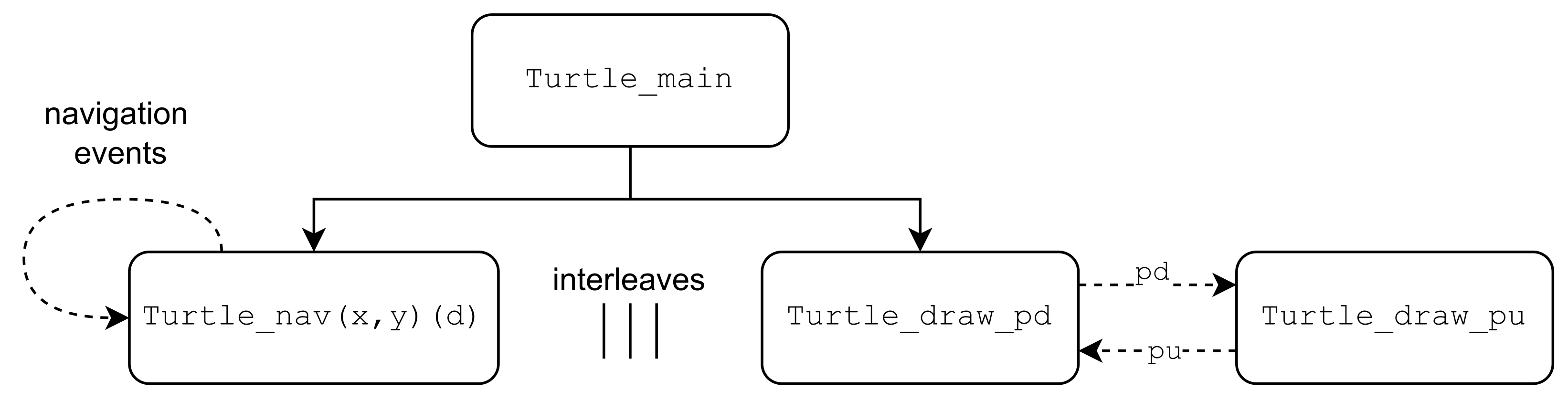
CSP supports specifying complex systems as an interleaving of smaller processes, each specifying one function. In this way, processes can be composed together to form larger systems, and the behaviour of the composed system can be analyzed using the FDR model-checker. We used this feature in the architecture of our model, as shown in
Figure 3. The architecture in this figure consists of four named CSP processes, and we discuss each of them in the following subsections.
3.1. Main Process
At the top of
Figure 3,
Turtle_main represents the turtle, which is the high-level process that we can make assertions about to check the properties of our system as a whole. The
Turtle_main process is composed of the
Turtle_nav and
Turtle_draw_pd processes running interleaved, and it passes the model’s initial parameters to these more specialised processes. This modular design strategy of composing it out of smaller specialised processes makes it more easily extensible. The navigation and drawing functionalities can be easily separated in this case as they run independently of each other and do not need to synchronise on any events. This independence of processes is why the interleave command can be used. If synchronisation were needed, CSP has a parallel operator that takes two processes and a set of events that they must synchronise on (meaning they would perform those events in unison).
This structure can be seen reflected in the code in Listing 2. The locations and direction parameters are taken from the main process to be used by the navigation processes. The separate brackets are to allow the process to be partially applied to its arguments.
| Listing 2. The main turtle process. |
![Robotics 12 00062 i002]() |
3.2. Navigation Process
Turtle_nav reacts to the movement and rotation events (, , , and ) and updates the turtle’s location () and the direction (d) that it is currently facing. To handle these different cases, Turtle_nav uses a different specialised process for each direction. Lines 4 and below, in Listing 3, show a snippet of how the movement forward and backward is broken up into these different directional cases. When the direction of the turtle is North (N), the Turtle_nav_North process handles movement, using its knowledge of the world dimensions to avoid moving beyond the boundaries. Special instances of Turtle_nav are synthesised by the toolchain to avoid obstacles. This internalising of the world knowledge means assertions about the turtle process amount to assertions about the system as a whole. However, separating the world state from the turtle could be useful to allow for different assertions to be checked against the world versus against the turtle process. Lines 2 and 3 in Listing 3 show how the Turtle_nav handles the turning events with an auxiliary helper function change_direction.
| Listing 3. A subset of the navigation processes. |
![Robotics 12 00062 i003]() |
3.3. Pen Processes
The Turtle_draw_pd process only interacts with the pu event, before transitioning to being the opposite process (called Turtle_draw_pu) that only waits for a pd event. We assume that the pen always starts down, and thus, we begin with the Turtle_draw_pd process, as this is the default behaviour in Turtle. Note that the Turtle package does allow the pendown() method to be called while the pen is already down, but as this has no effect, it would always be redundant to include in an execution plan. This setup ensures that redundant calls of this form to penup() or pendown() do not occur. Listing 4 shows the simplicity of implementing this in CSP.
| Listing 4. The two processes handling the pen state. |
![Robotics 12 00062 i004]() |
Thus, we have outlined our modelling approach. Next, we explore our CSP2Turtle toolchain.
4. CSP2Turtle: Our Python Toolchain
This section describes the main contribution of this paper: CSP2Turtle (code and
Turtle package model:
https://doi.org/10.5281/zenodo.7831832, accessed on 19 January 2023), a prototype toolchain that verifies a CSP plan for a turtle within a user-defined environment and (if the execution plan passes the checks) synthesises Python
Turtle code that corresponds to the plan. CSP2Turtle uses the CSP model of the
Turtle package that we describe in
Section 3.
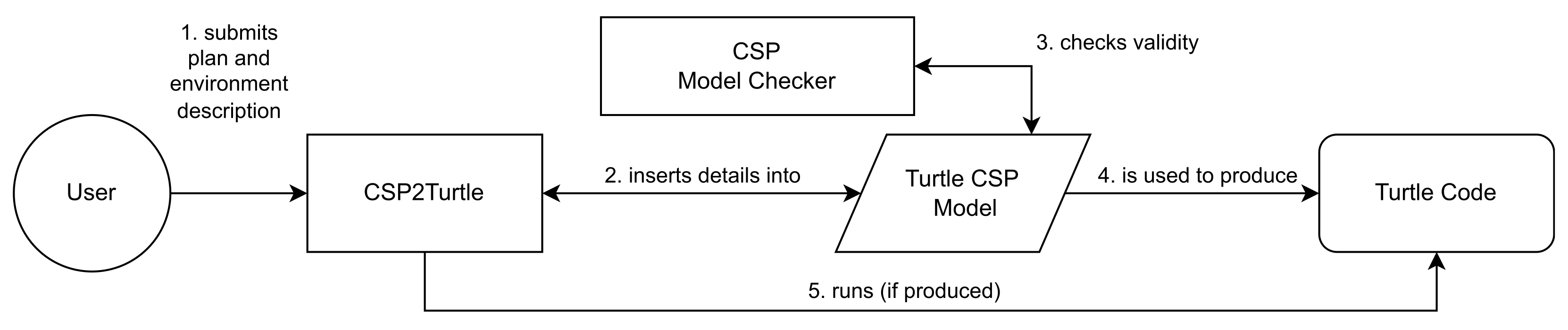
Figure 4 illustrates the workflow for the CSP2Turtle toolchain. CSP2Turtle can accept the environment description and a CSP plan specification in one of two modes:
File Mode, where the information is read from an input text file; and
Interactive Mode, where the user inputs the information at the command line (see
Section 5 usage examples). These two modes only alter how the information is fed to CSP2Turtle, and whichever mode is chosen, the other steps in the workflow remain the same.
The plan and environment information are combined with our CSP model of the
Turtle package (
Section 3), which produces a turtle model that can only navigate within the confines of the world specified by the user. Issuing commands that, for instance, ask the turtle to move beyond the edge of the environment or enter an area specifically marked as impassable, are invalid. Removing these options from the model makes it possible to check that the CSP plan obeys the restrictions of the environment. The toolchain then executes FDR’s command line program
refines. This program automatically verifies the model against the environmental restrictions and goal location. If a valid plan that uses at most one choice operator has been provided, then CSP2Turtle can generate and run a corresponding
Turtle Python program, giving the user a graphical output of the CSP plan that shows how it executes.
Below we discuss the core components of the toolchain: the environment specification, which is for specifying the world state (
Section 4.1); the planning language (
Section 4.2), which outlines the actions the turtle should attempt to undertake; and a description of the verification process performed by the model-checker to ensure correctness (
Section 4.3).
4.1. Specifying the Environment
The turtle’s plan is checked with respect to its environment, so properly specifying the environment is a key part of using CSP2Turtle.
The environment specification consists of five components: the world’s dimensions, a location in the world to be marked as a goal, obstacle locations, waypoint locations, and the turtle’s starting location. The obstacle and waypoint locations are optional and can be left blank. Marking a location in the world as an obstacle means the generated model will consider it impassable. The waypoints are locations on the map that must be traversed but are not the ultimate goal. Further examples of waypoints’ usage are given in
Section 6. Given that the world is a 2D integer grid, all these details can be specified simply. The world’s dimensions are a pair of positive integers describing the height and width of the grid; the turtle’s starting location, the goal location, and locations of obstacles, are all given as pairs of positive integer co-ordinates. Note the turtle always starts facing east by default.
In File Mode, the user writes a simple input file where each of the five components is given on a separate line that begins with the component’s name. For example:
startcoords: 0, 0
dimensions: 4, 4
goal-coords: 2, 2
obstacles: (1, 1), (3, 3)
waypoints: (0, 1), (2, 3) |
To correctly parse the input file, CSP2Turtle requires that the values are separated by commas and spaces, as shown above; removing this restriction is part of our future work to improve usability. In Interactive Mode, CSP2Turtle’s Command Line Interface (CLI) prompts the user for each component of the environment description.
4.2. Planning Language
CSP2Turtle uses a subset of CSP
M (FDR’s functional language that contains an implementation of CSP) to enable the user to specify the turtle’s plan. As previously mentioned, we provide CSP events that correspond to the turtle’s navigation and drawing commands (see
Table 2). A plan specification uses these events and three CSP operators: Simple Prefix, Sequential Composition, and External Choice (described in
Table 1). A plan specification is a CSP process; when combined with the declarations of the events that correspond to methods in
Turtle, it can be analysed using FDR. These three operators have clear uses in a plan specification: the Simple Prefix and Sequential Composition operators link instructions (events) together, and External Choice enables the user to describe multiple options. Our future work involves exploring the utility of other CSP operators for specifying plans.
Using the building blocks of the navigation and drawing commands, the user can construct a specification of the turtle’s required behaviour. The behaviour of the operators mirrors their usual CSP semantics. The Simple Prefix infix operator (written ->) links an event to a process, and we use it to denote performing one Turtle method and then (potentially) another. For example, if part of a plan specification reads fd -> lt, this states that the turtle should “move forward, then turn left”. The External Choice infix operator (written []) provides a choice between following the actions on its left or its right and should be bracketed to clearly show its scope. For example, if part of the plan specification reads (lt -> fd [] rt -> fd) this states that the turtle should “either turn left and move forward or turn right and move forward”, indicating that either is possible.
The Sequential Composition operator (written ;) is similar to Prefix, but it links one process to another. For example,
A ; B performs process
A and, once it has terminated, performs process
B. Some specifications in CSP are interpreted as a process on their own and thus need a Sequential Composition to continue adding to the specification. For example, if our plan reads:
then this is intended to state that the turtle should
“either move forward and then left, or move left and then forward; whichever choice is taken, then set the pen to be up and move forward”. The Sequential Composition operator is needed to link the final two events
pu -> fd to the External Choice. The
process immediately terminates; however, it is necessary for the CSP
M typechecker.
4.3. Plan and Environment Verification
CSP2Turtle checks for three properties: that the goal location is reachable, that the plan does not go outside the environment or collide with an obstacle, and that the plan reaches the goal.
Checking if the plan is valid means checking if the turtle navigates within the constraints of the environment while also reaching the goal along
all possible paths (if several routes are included using External Choice). This is achieved by verifying that the plan corresponds to a possible trace of the robot’s environment using the following assertion:
This is a trace-refines assertion, meaning that FDR will check that the process defined by the given plan implements the specification in the Turtle process. The Turtle process here encapsulates the whole model, meaning that this is the process we want to make assertions about. This is really two checks in one, as it asserts that the goal location is reachable, and that the plan given does actually reach it.
If this first assertion statement fails, it may be the case that the goal is reachable but the plan given does not conform to the world or does not actually reach the goal. To allow for this possibility, another check is performed, which makes FDR explore the state space to check for reachability.
Unlike the earlier example, this assertion is made directly on the navigation process because we are only concerned with the navigation events, not the pen-related events. Note that this is our modified version of the navigation process, which adheres to the environment description. As such, it cannot move outside of the environment or through any obstacles. This assertion works by forcing FDR to check if there are deadlocks, and due to the model design, these can only occur if the turtle reaches the goal. If a deadlock is found, then the goal is reachable; FDR provides an example trace to this state, which in this case is a valid path to the goal. This is a check on the environmental situation rather than the turtle, as it is only concerned with the location of the goal and potential obstacles between that and the turtle’s starting position. The results of these checks, pass or fail, are displayed to the user.
If the plan given is a valid trace of the system, a corresponding Turtle program will be produced, saved, and ran, with the graphical output being visible to the user. If the trace is invalid, then no program is produced. The next section illustrates our approach via an example, including code snippets and screenshots from our toolchain.
5. CSP2Turtle: In Action
In this section, we show examples of how CSP2Turtle works in practice, in both File Mode and Interactive Mode. We provide examples of CSP2Turtle at runtime with sample maps illustrating the turtles’ worlds.
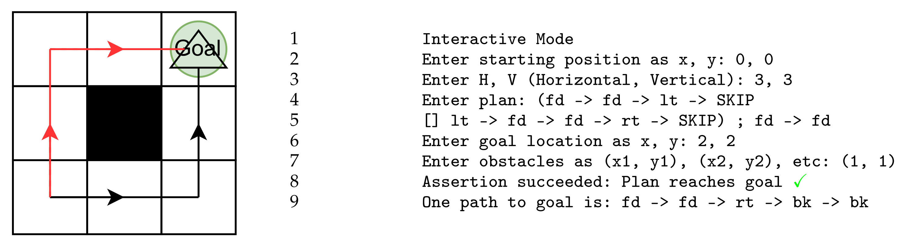
In our maps, filled-in squares represent obstacles or impassable terrain; a triangle represents the turtle; solid lines represent the possible drawings that the turtle makes as it moves; and arrows show the direction of movement. The bottom left square of our map has co-ordinates (0, 0).
Figure 5 and
Figure 6 show the usage of Interactive Mode, which is started in one of the two following ways:
./csp2turtle -i
./csp2turtle --interactive |
Figure 5 shows an example where all possible paths, defined in the plan, lead to the goal. CSP2Turtle, therefore, accepts this plan, informing the user that the assertions have succeeded. Note that the use of the choice operator is indicated here with a black line for one path and a red line for the other. This is how it would appear when run in CSP2Turtle, the map and obstacles would not be indicated, but the lines drawn by the turtle would be the same. There is an obstacle at co-ordinate (1,1) and CSP2Turtle produces another possible trace leading to the goal that navigates around this.
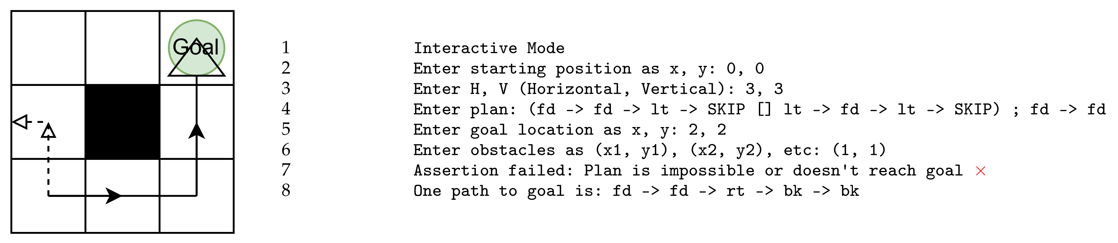
Figure 6 shows the case where the CSP2Turtle’s assertions fail. This example is similar to that in
Figure 5 but differs in the plan input in the right-hand side option of the choice operator. This new plan, followed by
fd -> fd would lead the turtle outside the map. For this reason, CSP2Turtle’s assertions fail, as it requires all paths to succeed for a task to be deemed successful. We see again that CSP2Turtle informs the user and CSP2Turtle produces a working example that would reach the goal.
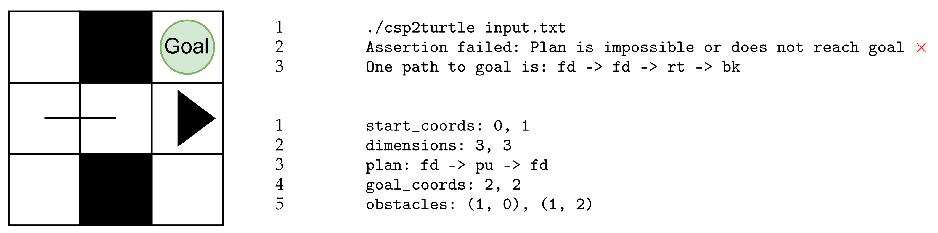
Figure 7 and
Figure 8 depict File Mode, started by the
csp2turtle command and followed by the name of the input file.
Figure 7 illustrates when the file
input.txt is passed as an argument at the command line. Even though the turtle would not exit the world boundaries, it fails to reach the goal. Therefore, CSP2Turtle reports that the assertion fails and it produces a path that would successfully lead the turtle to the goal. We have also listed the contents of the
input.txt file here. Note that the turtle’s starting location is at co-ordinate (0,1), where the default state of the turtle is with the pen down. The turtle follows the plan, moving forward. The
pu event causes the absence of a line from co-ordinate (1,1) as the turtle moves forward once again.
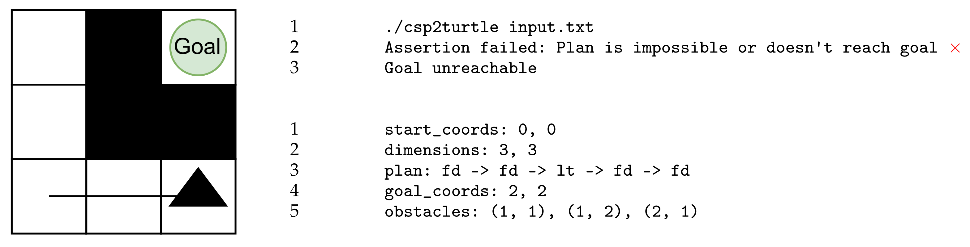
Figure 8 illustrates where the execution plan provided in the file
input.txt does not lead the turtle to the goal. In addition, no other path that would bring the turtle to the goal was identified by FDR. The path the turtle attempts is blocked by an obstacle at co-ordinate (2,1). Similarly, all other routes are blocked off.
6. Validation with Case Study
To demonstrate how our tool could be used, we examine the Inspection Rover case study in [
20]. They lay out a wide range of system requirements drawn from NASA safety and formal verification guidelines [
21], ensuring a broad and robust set of safety properties for us to examine. Here we demonstrate how CSP2Turtle can express and verify a selection of the requirements laid out in [
20].
The authors lay out the three main system requirements necessary to ensure that the rover works safely and accurately:
R1: The rover shall not run out of battery.
R2: The rover shall not collide with an obstacle.
R3: The rover shall visit all reachable heatpoints.
These main requirements are themselves divided into multiple sub-requirements. The authors employ three NASA Ames tools FRET, COCOSIM, and AdvoCATE, as well as Event-B, to verify these sub-requirements, while others cannot be verified without field testing. This indicates the scope and challenges faced and allows us to consider the properties we can reason about in our toolchain versus several other toolsets.
Table 3 lists the full selection of requirements that we investigate in this paper. Many of the requirements that are not mentioned involve sensory inputs such as a vision system or speed measurement and hence are outside the scope of our abstracted model in its current state.
The design of CSP2Turtle means that the requirements under R2 are mostly true by construction. When checking the validity of the user-supplied plan, FDR starts from the given initial location, similar to any possible plans it generates, which is what is needed for sub-requirement R2.3. For the two sub-requirements in R2.4, the toolchain will return negative results or produce an error if an obstacle is in the initial rover position or an obstacle coincides with a waypoint, respectively. The CSP model explicitly does not allow paths to move through locations marked as containing obstacles, covering R2.5 as FDR calculates its path based on the model and environment.
To model heatpoints (R3), we introduce some other elements that are not from Turtle into our CSP model and toolchain. A new channel of events is added in the synthesised CSP model to represent arriving at one of these waypoints. We denote them “waypoints” not “heatpoints”, as we abstract away the temperature measurement for use in our model. This channel is parametrised by an integer, which is bounded by the number of waypoints. This means there is a distinct event for the first waypoint, the second waypoint, and so on. These events can be inserted into the plan at the desired points, and FDR will check if they correctly match with the specified locations.
| Listing 5. Successful plan with waypoints indicated. |
![Robotics 12 00062 i005]() |
Additionally, the positions of the waypoints given are checked against the turtle’s starting location, satisfying the sub-requirements R3.1.1 and R3.1.3. Sub-requirement R3.2 is not directly checked by the system but would instead be expressed in the plan or plans provided by the user. The responsibility then lies with the user, or with any plan-generating software they use. However, the use of parametrised channels for waypoint events makes it easy to avoid using the same waypoint more than once, as they are each distinctly numbered.
For the work presented in this paper, we focused on two core requirements R2 and R3 of the Inspection Rover Case study. We did not study R1, which manages battery power usage, as that would involve making changes to the turtle agent, which is outside the scope of the current model. The current model and toolchain make it very easy to add additional elements to the world as the turtle’s environment is a featureless blank slate. This means that there is not much complexity in adding obstacles or waypoints, but elements such as the battery that modify the agent are different. However, this could be included as we increase the complexity of our model in future work. The authors of [
20] take a similar approach starting with an abstract model, which is then refined. A future step in this work will be to use more detailed and realistic assumptions, modifying the environment with the relevant parameters.
7. Evaluation
CSP lends itself well to modelling the core components of the Turtle package. The concepts of processes and events were broad enough to not constrain the design approach and naturally mapped onto the turtle and its methods. This made the initial modelling decisions easy and provided a good foothold to explore different possibilities for the model. This meant they were quick to prototype and test in FDR.
The documentation and tooling surrounding CSP were also mature and well-resourced enough to make learning straightforward for a beginner. Detailed textbooks, such as [
22], provided a good theoretical and practical introduction while also having more background detail when necessary. The CSP
M implementation and model-checker, FDR, were essential in the development process. Having a quick idea-prototype model-test cycle allowed for lots of exploration, especially at the early learning stages. FDR enables a user to
probe a process and step through its events, and this probing feature was very useful for exploring edge cases in the model and finding bugs.
Adding a Python layer introduced another layer of the system that is not verified, which weakens the overall robustness of the system. This could be improved by finding ways to better integrate the Python layer into the verified CSP system. In
Section 9, we discuss using software verification tools to ensure the Python components work as intended. This added layer of complexity enabled tasks that would not be possible in pure CSP but made it harder to discern if errors were in the Python program or the CSP model. Both Python and FDR are implemented on Linux, Mac, and Windows, meaning the toolchain is reusable across the major platforms, with only minor adjustments.
Other aspects of CSP also influenced design decisions. We were restricted to movement on the integer grid due to the types available. The Turtle package has a method begin_poly that marks its current location as being the start of a polygon. If the corresponding end_poly method is called upon, it will return to the location marked as the beginning, completing a drawn polygon. Due to CSP’s process-based semantics, implementing a method that uses this long-term memory requires the introduction of other processes or parameters to store this information. This is more complicated compared to languages that use conventional variables for storing information. In addition, implementing the plan descriptions as a sub-language of CSP was a very natural choice and came with a lot of ease of implementation benefits. It makes the semantics of the planning language much more obvious and well-defined, removes the need for translation to the language of some other model-checker, allows us to utilise FDR for parsing, and means the user does not have to learn another separate language to understand the whole system. This was a large boost to prototyping ideas and simplifying some of the design choices that come with making any sort of language.
Using CSP as the planning language did, however, come with some drawbacks. It is possible that there are some constructs that would be useful for expressing plans that are not base CSP operators. Despite these, it was still a positive design choice for this project.
The CSP model underlying CSP2Turtle was rewritten several times throughout the course of the development. This was prompted by design choices that had limited usability or extensibility. As a result of these changes, the current state of the model is highly improved over earlier iterations. However, further use has exposed points that could still be improved, and any further work on this project may involve another restructure. This would likely be necessary if major new features were to be added.
While the current usage of the tool is simple and effective for its stated goals, there are several quality-of-life improvements that could be made. For instance, the ability to run it over multiple files or the option to save paths that FDR outputs. Interoperability with other tools could also be encouraged by changing the input and output formats to a more standardised format such as json where appropriate.
A preliminary investigation was made into the scalability of the tool, the results of which are shown in
Table 4. All of these measurements were taken on an M1 Macbook Air, using the Unix
time -p command, and rounded to the nearest second. The turtle always started at
, the goal in the top right (grid size—1), with no obstacles, and a dummy plan of
was given for each. This means it was timing the ability of FDR to search an increasing state space for a valid plan. We see that even when there are many more states to search, it still performs in a reasonable time, especially taking into account that these are intended as offline checks. While the scalability of the tool was investigated, there may be further improvements that could be made to ensure the system remains performant even as the state space grows larger. This could be particularly important if major new features are added to the system in the future, such as a further range of motion for the turtle.
8. Discussion
In this section, we discuss the Olympian view that we have taken with respect to the environment of our turtle robots. We also discuss the possibility of using our toolchain for educational purposes.
8.1. An Olympian View
Our overall approach takes an
Olympian view of the turtle’s environment, meaning that we have perfect knowledge of the grid-world, the locations of the obstacles, and the turtle’s location. This paper is focused on exploring the utility of CSP operators for describing plans for a mobile agent, so the assumption of perfect knowledge of the environment does not detract from our aim and is an approach frequently taken in the literature [
6,
23,
24,
25]. However, these assumptions would need to be relaxed to adapt our approach to robotic agents operating in the real world, or even a more realistic simulation of the real world.
When using formal methods, it is common to simplify and make abstractions of the operating environment in order to ensure that the verification is tractable and focuses on the critical elements. However, this does result in a
reality gap, as mentioned in [
4], where the verified system and its assumptions may differ from the final system as deployed in its operating environment. In complex systems, such as robotics, it is therefore also necessary to use the verification conditions to inspire test cases as well as monitors in more detailed simulation environments and the final deployed system. This helps to ensure that formal verification results are preserved at runtime in the associated deployment environment [
5,
26].
If we relax our assumptions of perfect knowledge so that the turtle is operating with a map that was either uncertain or unknown before deployment, we would need to adapt our approach to cater to this more realistic environment. We discuss two routes for this extension, which could be applied together.
The first route is to provide a richer model of the environment. In CSP, this would involve extending CSP2Turtle to have a process to represent the user-defined environment and then use the process to track the turtle’s progress through the environment. The addition of dynamic obstacles to the environment (for example, to represent people or a door that might be open or closed) could be captured using nondeterminism in CSP, or by using an extension to CSP. For example, if the obstacles vary according to some timing property, then we could use tock-CSP [
13]; or if they have continuous dynamics, then we could use Hybrid Communicating Sequential Processes (HCSP) [
27], which adds continuous variables and differential equations to CSP. Another way to describe a richer model of the environment would be to leverage the integration of CSP with B [
28] or Event-B [
29], using these languages to describe the environment and retain our model of the
Turtle package in CSP. Both of these approaches are likely to increase the verification time as the model/combinations of models become more complex and, in the case of HCSP or the combinations of CSP with B/Event-B, would require the use of different verification tools. Further, enriching the model of the environment, in any language, requires us to learn about the environment and its possible behaviour (for example, when and where a mobile obstacle might move), so it is still susceptible to the reality gap [
4].
A second route to cater to a more realistic environment is to use Runtime Verification (RV), where the behaviour of a running system is compared to a formal model of its intended behaviour. CSP does not yet have an RV toolset, but the development of an RV approach for CSP would enable the reuse of our existing models at runtime. This could be used to compare the turtle’s behaviour to the user’s execution plan (which, we remind the reader, is also a CSP process) to ensure the turtle is behaving according to the plan. If the behaviour is different, then this indicates the possible violation of a design-time assumption about the environment [
30]. Without this kind of directly applicable RV approach, our models (or the execution plan) would require translation to another formal language (such as Temporal Logic) to enable RV in an existing framework. Alternatively, we could extend the CSP2Turtle toolchain to include a (non-formal) monitoring module that compares the turtle’s behaviour to the execution plan and the environment description and triggers some remedial action if they do not match the user’s original input. For example, if the execution plan’s next action is to move forward and the turtle cannot because of an obstacle, then CSP2Turtle could update the environment description with this new information and re-run the verification to see if the goal is still reachable. As mentioned in
Section 5, CSP2Turtle can show the user a plan that reaches the goal (if there is a possible plan); this functionality could be used to enable CSP2Turtle to suggest a new route to the goal, if one is available, in the event that a previously unknown obstacle makes the original plan invalid. However, the
Turtle package has no concept of obstacle or the grid-world assumed by our models, so the architecture of how CSP2Turtle executes the
Turtle code would also require an extension to capture this information and provide the feedback that an RV approach would need [
8].
Clearly, a combination of a richer model of the turtle’s environment with a runtime verification/monitoring approach would provide the most robust adaptation of our current approach to suit a more realistic environment. The richer environment model would add confidence that the design-time verification can capture the available information about the real environment, helping to close the reality gap. Applying RV would add confidence that the turtle’s runtime behaviour matched the models and that there is some remedial action if it does not. However, this requires additions to our models and tools and to how we execute the Turtle code. The starting point for this is to build a richer model of the environment using CSP to determine what information is needed about the environment and investigate the limitations of the approach. This expansion of our approach is left as future work.
8.2. Teaching Formal Methods
In addition to the main motivation for this work, another potential application area is in teaching formal methods. Our toolchain provides a route to help students of CSP to visualise what a process does. By writing a CSP process as a plan, using our planning sub-language of CSPM, a student can receive quick feedback—either from FDR’s counter examples or from the turtle running on-screen—about what the process does.
We envisage a generalised version of the CSP2Turtle tool chain that allows both the current functionality—checking if the plan reaches the goal and is feasible within the given environment—and a simpler mode, without a goal location or environment bounds. The simpler mode could be used to introduce the student to CSP operators by letting them explore how the turtle reacted to commands. For example, they would be able to write a CSP plan: and then run the plan and see the turtle move forward twice. This visualisation provides the intuition (or visual confirmation) of how the prefix operator (→) works and could be repeated for the other operators and combinations of operators.
To implement the simpler mode for CSP2Turtle, we could modify the toolchain’s main Python program so that it can accept input without a goal location. It would be important that the normal mode of operation still checked that a goal had been given, so a flag could be added to indicate to CSP2Turtle in which mode it should operate. In this simpler mode, the toolchain would still verify that the plan keeps the turtle within the confines of its 2D world, so the student would still receive feedback from the formal verification part of the toolchain. Once verified, a plan would be translated into a Turtle program in the same way as the toolchain does already. This simplification of the toolchain would support the sort of exploration of CSP described previously.
When the student is familiar with the operators that form the building blocks of CSP processes, the toolchain’s current functionality could be used to pose particular problem maps for the student to solve. This would work as an educational game, with increasing levels of difficulty and maps that require more operators to solve. Here, some of our proposed extensions could be useful for providing extra challenges; things such as multiple agents, different environment topologies, and dynamic environments.
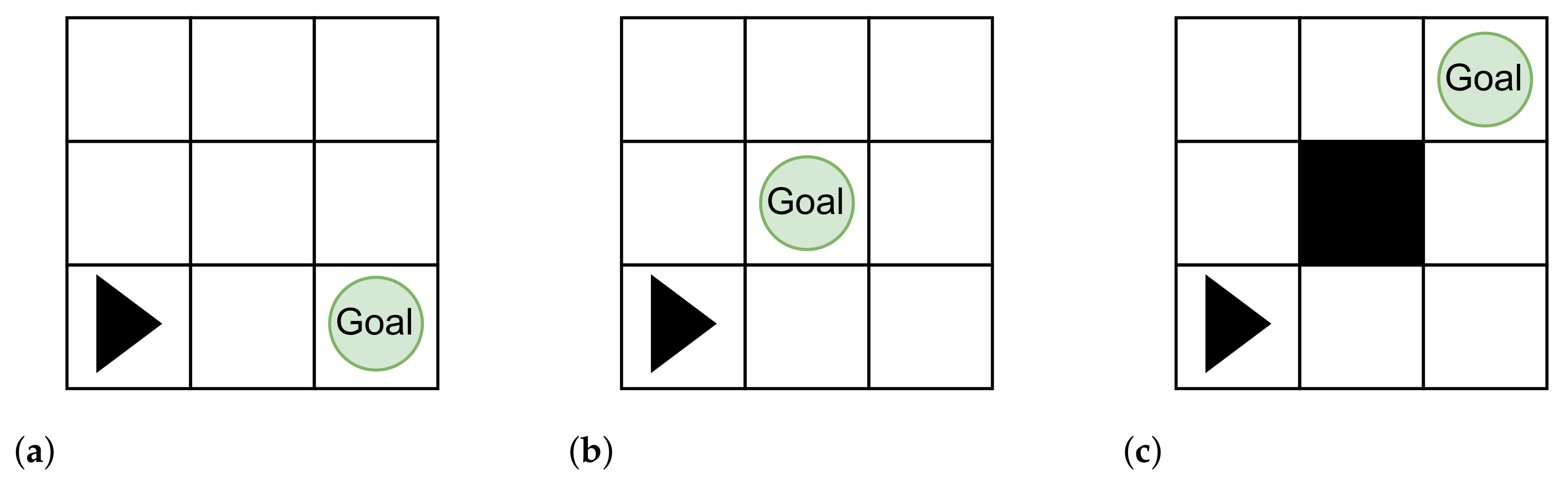
For example, the three problem maps shown in
Figure 9 illustrate increasing levels of difficulty, which each need steadily more complicated plans with more operators. The simple map in
Figure 9a only requires the student to know how the prefix operator works; it can be solved with the plan
. The map in
Figure 9b introduces the student to turning, so they could solve the map with the plan
. Finally, for the map in
Figure 9c the student would be asked to provide a plan that gave both possible routes to the goal. This would introduce them to the external choice operator (□), which is needed to solve this map. The student would need to submit a plan such as:
to solve the map.
Clearly, this educational approach would need careful planning, and course resources would need to be developed. The current toolchain provides the foundation for the features described here, enabling this direction of future work. The simpler version of the toolchain is
less complicated than the current work, so the majority of work for this direction would be in carefully designing the maps and course resources. However, this approach could be very helpful for engaging students who need to be able to visualise problems before they are able to solve them. It also shares similar benefits to the sort of fast, visual feedback provided by languages such as Scratch, which are often used in teaching programming to younger learners. ((
https://scratch.mit.edu/, accessed on 19 January 2023) is a block-based, graphical programming language where “scripts” are attached to “sprites” on a “stage”. When the program is run, the sprites can be seen reacting to their script. This means that programming errors often produce odd, unexpected, or hilarious behaviour.)
9. Conclusions and Future Work
Robotic systems are often safety-critical systems, meaning that if they fail they could cause harm to people or property, or systems that themselves operate in hazardous environments and must be fault tolerant. For example, robots used to inspect hazardous nuclear storage facilities or on product assembly lines. These kinds of systems require careful verification during their design and implementation to ensure that they behave correctly. Correct behaviour for these systems depends highly on the context; it could range from ensuring a robot does not enter dangerous terrain to guaranteeing no defective products in automated assembly lines.
In this paper, we describe CSP2Turtle, a prototype toolchain that verifies a CSP plan for a mobile agent (the turtle) within a user-defined environment and (if the execution plan passes the checks) synthesises Python Turtle code that corresponds to the plan. CSP2Turtle enables quick checks on the validity or possibility of certain actions (performing a series of steps, reaching a goal) of the robotic turtle agent given certain movement constraints (obstacles, world size). In this paper, we extended our previous work to expand plans for the turtle robot, make the tool more flexible, and produce more feedback for the user of the toolchain. We also improved the usability and investigated its scalability and possible uses of our CSP2Turtle toolchain.
Future work includes restructuring the design to capture Turtle’s begin_poly() and end_poly() functions, which facilitate the creation of arbitrary polygons by recording the turtle’s movements. This type of memory-storage driven action is less amenable to implementation in CSP but is still possible. The scalability of these methods and the core model to larger-scale systems could be tested.
Methods can be developed to alter the topology or geometry of the world. This could involve changing the topology to objects such as loop or torus or the geometry to non-rectangular shapes. This could allow it to handle non-rectangular world types, which would open it up to a wider range of robotic systems, for instance, ones that might have to explore unknown environments. An adaptation in a similar vein would be increasing the turtle’s range of motion. Allowing diagonal movement and a variable move distance would make the model less abstract by no longer confining it to rigid grid movement. This would make it more applicable to reasoning about robots that have more freedom of motion or have to navigate in circumstances that require more precision. This would make it a more accurate model for both the turtle and other potential real-world robots. This may require using parametrised channels or allowing for more options but from a fixed range (30°, 45°, etc.). The plan processes could be designed to use more of the CSP operators, such as interleave (⫴), to enable describing a whole new range of behaviours, such as multiple agents. This is an area where CSP has been successfully applied before [
31].
The CSP variant tock-CSP could be used to introduce the notion of discrete time into the model; while the
Turtle package does not include time restrictions, they could be included in the translation manually (by using the
sleep() function, for example) and would be a useful addition when adapting our approach to real-world robotic systems. Another avenue of future work is verifying aspects of the Python components of the tool chain. A way to achieve this could be to use Nagini [
32], a library for verifying Python code that is written as annotations inside of the Python program itself. Nagini could be used to make and prove assertions about the correctness of CSP2Turtle, for instance, if it inserts the plan into the model correctly, which would help avoid errors that can occur from adding more programming complexity.
As we talk about in
Section 8.2, we are also interested in examining the potential of tools like this in promoting and furthering education in formal methods and robotics.
Turtle’s visual feedback from its drawings and different modes of interactivity through script or command prompts could be used to introduce and motivate a technical subject such as formal methods in a novel way. In line with this, the robustness of the input language itself could be enhanced. We believe there is potential to further develop CSP2Turtle in this area, following a review of existing formal method teaching approaches.
The long-term goal of this project is to extend and adapt the ideas and approaches explored here to develop tools to perform practical robotic system verification in Python. This may involve extensions, restructuring, or changing approaches, but it will be grounded in the technology explored and lessons learned during this work.


