2. Related Works
The most popular gripper type used on Pick and Place robots is a vacuum gripper [
8]. Its main limitation is that it is designed for lifting flat, smooth parts and materials [
4,
9], thus it is not suitable for curved parts of non-standard shapes or products with a high porosity [
3].
Finger grippers are more suitable for picking non-uniform objects [
9], making a parallel pneumatic gripper with two fingers [
10] the second most popular solution for the industrial grasping device. To compare with their electric counterparts, pneumatic grippers of the same sizes have a smaller weight, a greater grasping force and a higher grasping speed [
11]. Moreover, they usually have a lower price [
3,
11]. However, the pneumatic grippers generally have only two stable states (opened or closed), so it is difficult to control the grasping force while handling fragile objects. Control of the grasping force via air pressure is possible, but has limited accuracy of the grasping force control. Thus, to the best of our knowledge, the only robust and cost-effective way of controlling the grasping force of a fingered pneumatic gripper with a high precision is to install an additional force regulation mechanism on it [
11].
Pneumatic grippers and other pneumatic systems have been widely used in different industries for decades. Meanwhile, the results of a critical review of pneumatic grippers’ energy efficiency has shown that despite the lower price of pneumatic actuators, the electrical actuators with a comparable force output have lower life-cycle costs. This difference stems from the fact that for the operation of pneumatic grasping devices at the enterprise, a large amount of compressed air is needed to produce, for which a large amount of electricity is spent. Reducing the volume of air consumed and the compressor’s power could solve this problem. However, the poor efficiency of end-use pneumatic devices, e.g., linear cylinders, makes this problematic [
12].
Electrical grippers provide a precise control of fingers’ position, speed, and acceleration. Moreover, they are often integrated with force sensors, making it possible to gently manipulate soft and fragile objects [
3,
13].
One of the most advanced solutions for the classical electric parallel gripper is a gripper installed on ABB YuMi Robot. It has a low mass and can precisely dose the grasping force, thus being suitable for manipulating fragile objects. Due to these advantages, it is often used as a reference design in scientific papers dedicated to the grasping topic [
14,
15,
16].
Pick and Place operations in industrial application often require rotating an object around a vertical axis in addition to transnational movements. Such a motion is usually implemented with two separate motors: one to move the fingers and the other to rotate the whole gripper, including the first motor. In 2013 Schunk introduced a gripper-swivel unit [
17], where the motor used to close gripper’s jaws is statically mounted inside the gripper and does not move during rotation. This type of gripper requires that the torque of its rotating part generated by the second electric motor is multiple times greater than the torque of its gripper unit generated by the first electric motor upon reaching a terminal stroke position of the jaws. Thus, enlarging of the grasping force will either require a larger and a more powerful motor for the rotation part, which would increase the mass, or higher gear ratios, which would decrease angular accelerations. A market-available version of the gripper built under the patent [
17] does not suit the requirements of Pick and Place operations performed by delta robots: it has a jaws closing speed of only 120 mm/s, rotation angle limit of 270 degrees, and no encoder on the rotation stage.
Another way to reduce end effector’s mass and increase its acceleration is to place one of the motors (usually the one rotating gripper) on a static robot frame transferring torque through the telescopic shaft [
18,
19]. However, to reach the mass comparable to pneumatic actuators another motor should also be removed from the robot’s flange. As one of the solutions several cardan shafts can be used to connect statically mounted motors and the end effector. Such design is used in some commercial robots by Codian [
20].
To enhance the variability of the objects that can be successfully grasped, several grippers with more complex mechanical designs have recently been proposed.
In the paper [
21] the authors introduce a set of grippers for a flexible industrial assembly. The authors propose three grippers for UR5 Universal Robots, working in collaboration. The first one is the Pincher Gripper—a classic electric finger gripper with one degree of freedom. The second one is Kitting Gripper with a soft adhesive pad to pick small objects. The third one is Rotary Gripper, which has two degrees of freedom which work as a collect clamp. This gripper’s design is the most suitable for the main Delta robots application. It has two in-build motors, one to open and close the fingers and one to rotate the fingers. This gripper proved its effectiveness in WRS Industrial Assembly challenge 2018. It was used to grasp parts by the outer or inner diameter and put them in their places. The main disadvantages of this gripper are as follows: it is designed to grasp objects with a limited number of shapes (cylindrical, triangular, and hexagonal); a screw transmission provides a low closing speed and a complicated force sensing.
Kim et al. [
22] introduced a three-fingers electric gripper with underactuated components, which makes it possible to switch between Precise Pinch and Compliant Grasp. The gripper proved the ability to grasp a variety of objects. The main drawback of the proposed approach is a complex mechanical design, which requires five motors and small-sized precise gearboxes. To achieve a high force and ensure that all the motors have a reasonable size, the authors propose to use high gear ratios. Thus, the ability of the grasping force sensing through the motor current is quite limited, while additional force sensors will complicate the design even more.
Another designs of two-finger underactuated grippers with enhanced grasping capabilities were introduced in [
23,
24]. Those designs are much more simpler than [
22] and require fewer motors. In [
24], the authors even managed to perform grasping using a single motor. However, this motor has to be mounted directly on a gripper, which results in an increased mass compared to pneumatic solutions. Generally, none of these grippers were designed to manipulate fragile objects, so they do not have precise force control. To solve this problem, an enhanced version of M
gripper equipped with an additional tactile force sensor was proposed in [
25].
It should also be mentioned that underactuated grippers are often designed as tendon driven, thus due to tendon elasticity they have a limited dynamic performance compared to the similar geared actuators [
26].
Another promising way to improve grasping capabilities of complex curved objects is to use soft fingers [
4,
27,
28]. It allows one to increase the contact surface between an object and the gripper without the need for additional actuators.
The common drawback of all the described grippers is that they all have a limited angle on which they can be turned around the vertical axis. Such a constraint appears due to the need to connect the rotating part of a grasping device with the robot’s frame by wires or pneumatic lines in order to operate the gripper.
Depending on the gripper’s type, the robot’s cabinet can be connected directly to the actuators with air tubes/power cables or interact with the gripper’s internal control unit. The latter case becomes more and more popular as it makes it easy to support different types of end effectors developed independently from the robot. Simple grippers are usually controlled by 24V digital outputs, while more complex ones use bi-directional industrial fieldbuses [
29].
3. A Novel Gripper Design
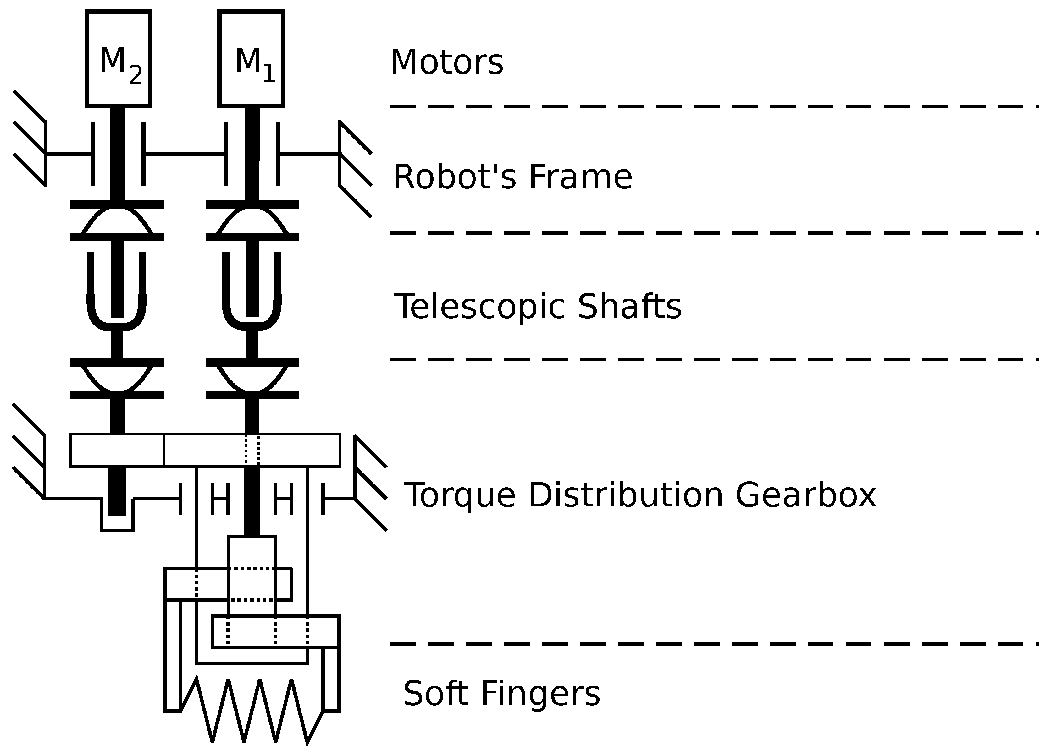
A novel gripper design is inspired by two degrees of freedom (DoF) epicyclic mechanism and consist of two motors mounted on the robot’s frame, two telescopic shafts, a Torque Distribution Gearbox, and soft fingers (
Figure 1). Motor M1 is in charge of opening/closing the fingers and providing desired grasping force, while M2 rotates the gripper around the vertical axis. Due to the design, these motors have a mechanical linkage that is compensated in real-time by the controller proposed in
Section 4.
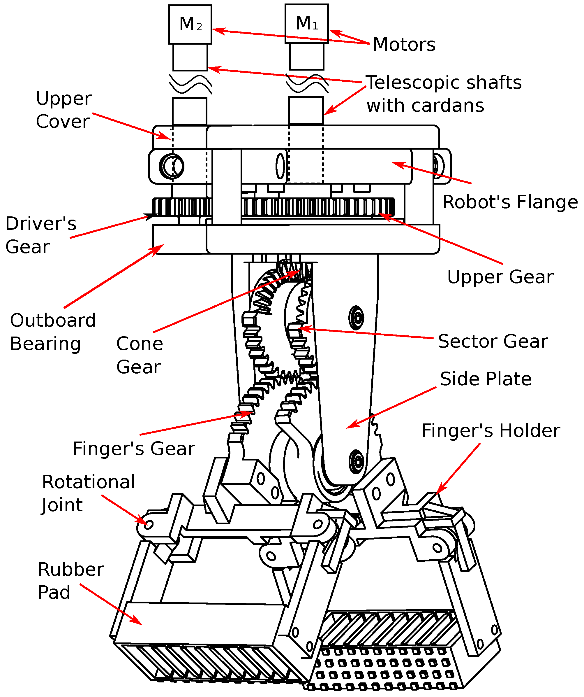
The key part of the gasping device is Torque Distribution Gearbox. It provides the ability to grasp and rotate handled parts without installing any DC motors on the gripper, which makes it possible to relocate them to the robot’s frame. To implement the proposed solution we have developed a mechanical design shown in
Figure 2. It includes the following parts: the upper cover, which connects the gripper to the robot’s flange, the outboard bearing, a set of gears, implementing the mechanism, which is mathematically equivalent to 2-DoF epicyclic mechanism, and 3D-printed soft fingers, similar to the ones introduced in [
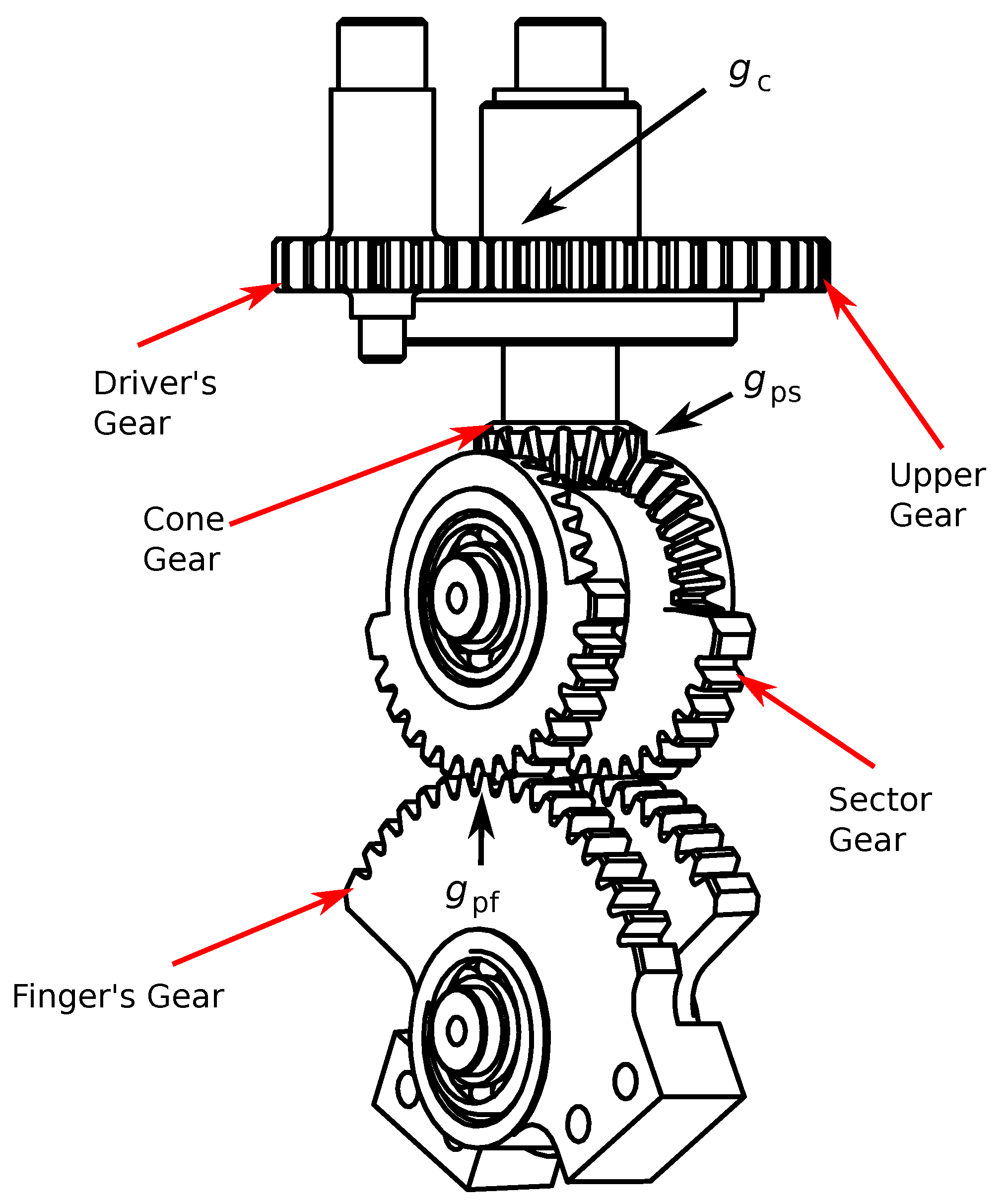
30]. The set of gears under the robot’s flange implements Torque Distribution Gearbox. Gearings are shown in details on
Figure 3. Shafts of Driver’s and Cone Gear are inputs of the Torque Distribution Gearbox. The shaft of the Cone Gear goes through the center of the Upper Gear, while the latter one is rigidly mounted to the bottom part of the gripper, including Sector and Finger’s Gears. As a result the upper gear rotation angle
is the same as gripper finger’s orientation angle relative to vertical axis.
If during operation Driver’s Gear moves simultaneously with Cone Gear in opposite directions the gripper rotates around its vertical axis. If the Driver’s Gear is fixed and Cone Gear rotates, the gripper’s fingers are closing or opening. The controller providing the desired rotation acceleration and grasping force, by applying specific torques to input shafts of Torque Distribution Gearbox is described in
Section 4.
The purpose of the soft fingers is to dampen the impact the moment they touch an object. In the case of rigid fingers, reaching the object will result in a step change of the reaction force, which will result in the grasping force overshot due to the limited reaction speed of the force controller. The use of the soft fingers makes the reaction force rise smoothly, making it possible to avoid the above overshoot.
The gear ratios of Torque Distribution Gearbox (
Figure 3) are labeled as following:
between Upper Gear and Driver’s Gear,
between Cone Gear and Sector Gear, and
between Sector Gear and Finger’s Gear.
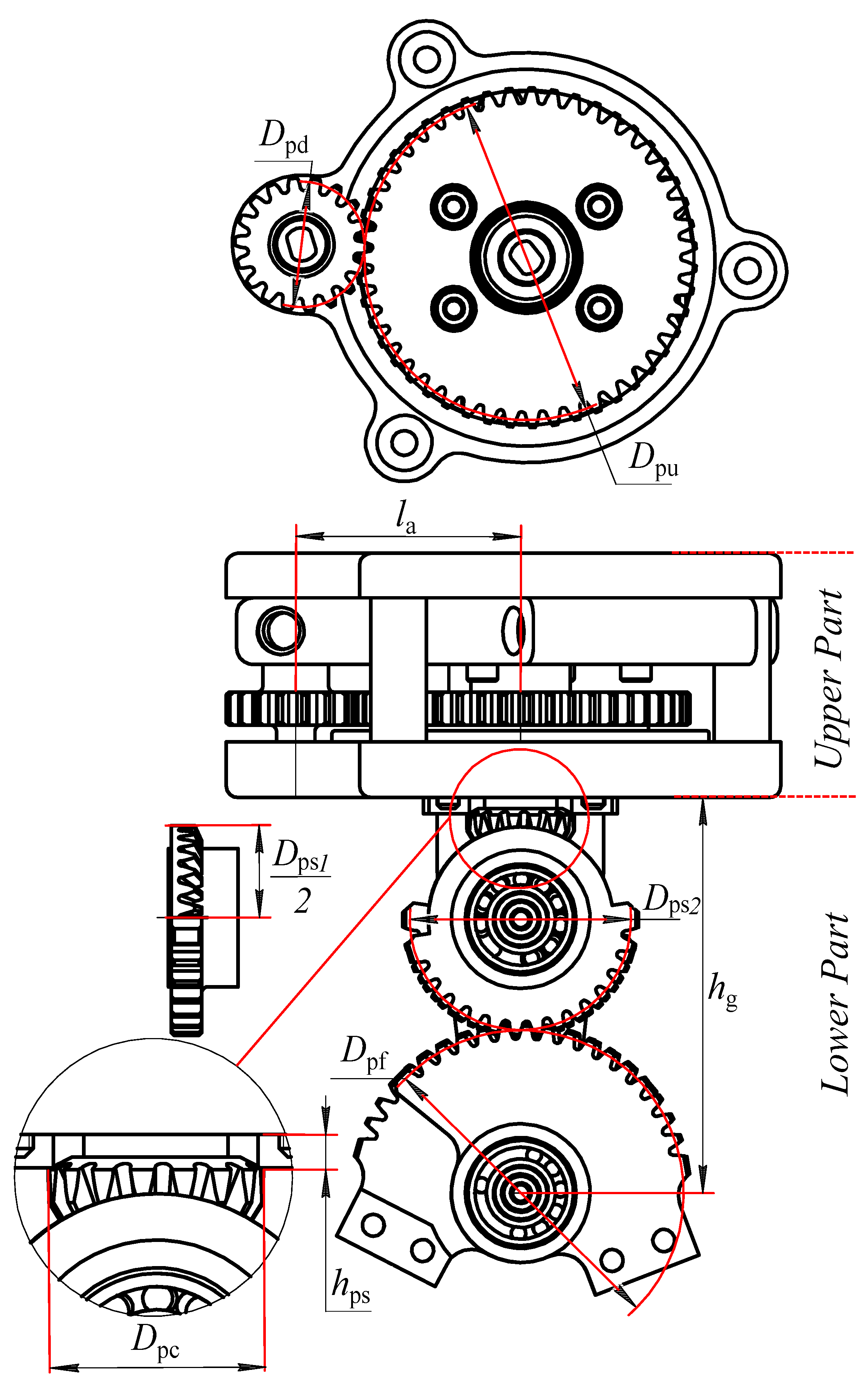
All the parts of the proposed design can be parameterized to meet specific project requirements. The upper cover size is mainly determined by the distance between motors’ axes
and the pitch diameters of Driver’s and Upper gears, defined as
and
, respectively, (
Figure 4). Those parameters are linked through (
1).
where
is gear ratio between motor
and the gripper.
The height of the lower part of the gripper mechanism
is defined by Equation (
2).
where
is the pitch diameter of the Finger’s gear,
is the pitch diameter of the cone part of the Sector gear,
is the pitch diameter of the cylindrical part of the Sector gear,
is the distance from the surface of the upper part of the gripper to the pitch line of the Cone gear.
Assuming that the linked gears have the same pitch parameters, their gear ratios can be evaluated using (
3).
where
is the ratio between the Cone gear and the Sector gear,
is the ratio between the Sector gear and the Finger’s gear, and
is the pitch diameter of the Cone gear.
The gear ratio
between the motor
and the fingers can be evaluated according (
4).
Finally, choosing gear diameters involves a compromise between the desired gear ratios for each motor and the gripper’s size, taking into account the limitations imposed by the strength of the gear’s materials, considering the size of proper bearings. The choice of materials and the design of gears’ pitches is not discussed in this paper as this topic is widely covered in books such as [
31]. Furthermore, it is worth mentioning that the gripper’s finger design is out of the scope of this research.
The proposed design ensures an unlimited gripper rotation obviating the need of passing electrical signals by slip rings and making it possible to choose motors according to the task. This can be considered as a significant benefit of the proposed solution compared to other types of grippers.
4. Rotation and Grasping Force Controller Design
To simplify the control we made a number of assumptions: (1) rotation of the gripper should start only after its fingers are closed and the desired value of is achieved; (2) the grasping force set point should be maintained constant between the opening and closing of the fingers; (3) the opening of the gripper should be performed only after the rotation is finished. These assumptions perfectly reflect most of Pick and Place operation performed by delta robots.
The proposed gripper design can be scaled to achieve desired size and force. Such scaling requires the controller to support a wide range of motors, in difference to ONROBOT, ABB, and SCHUNK grippers, which controllers are designed to operate with a specific motor. Thus, it was decided to use industrial servo drives from market-available families to provide desired unification. At the same time, this decision leads to limitations on controller structure that should be considered during its design.
As a reference servo drive in current research, one from the B&R ACOPOS series was used. These drives support asynchronous, synchronous, and DC-motors [
32] ranging from 50 W to 120 kW. Their controller generally consists of three Proportional–Integral (PI) control loops. However, using Smart Process Technology (SPT), it can be enhanced by adding new links and filters, evaluated directly on-board of the servo drive. Even though B&R products were chosen as a reference, the controller proposed in this section can be implemented on similar industrial servo drives produced by KEBA, Beckhoff, etc.
The Torque Distribution Gearbox can be considered as a 2-DoF epicyclic mechanism. Unlike most of the grippers, it creates a mechanical linkage between the motors used to perform gripper’s rotation and transnational movements of the fingers. In the mechanism the Driver’s gear plays the role of a driver and the Cone gear becomes the sun, which is connected with the satellite, implemented by Sector gear and connected to the Finger’s gear. Thus, the dependency between angular accelerations and velocities of the gripper’s parts can be expressed by Equations (
5) and (
6).
where,
and
are angular velocity and acceleration of the motor
;
and
are angular velocity and acceleration of the gripper rotation relative to vertical axis;
and
are angular velocity and acceleration of the Finger’s gear rotation. In the proposed gripper there is no dedicated sensor measuring its rotation angle. To measure it the encoder of the motor
is used. This encoder allows to meet precision requirements in the most of real industrial applications. In this case the gripper’s rotation angle
,
velocity and acceleration
can be evaluated using (
7).
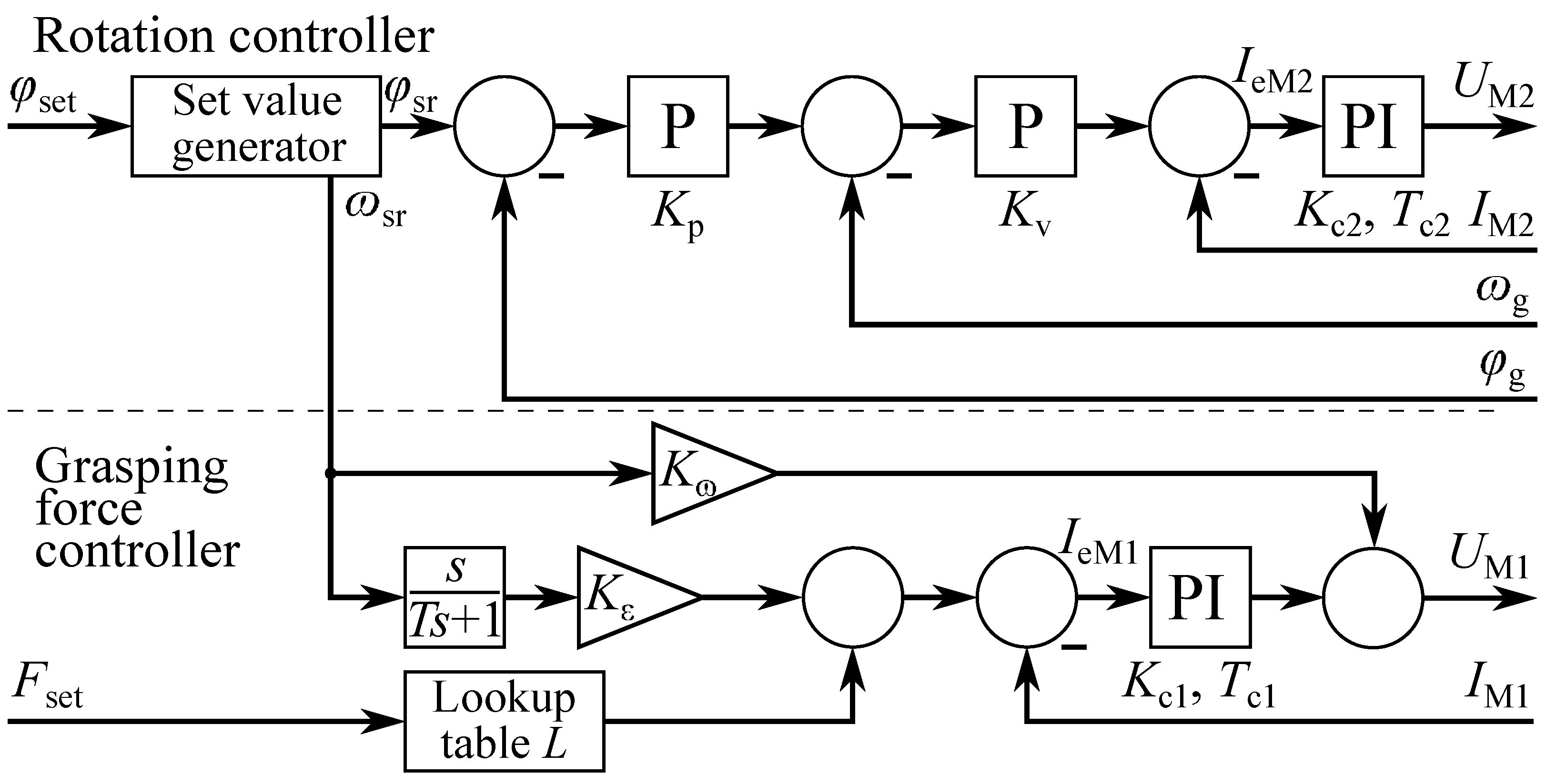
The Rotation controller for the proposed gripper can be implemented using well-known three level P-P-PI structure with current, velocity, and position feedbacks (
Figure 5). In this paper, we assume that a permanent magnet synchronous motors with Field-Oriented Control can be considered a DC-motor with current controller.
As mentioned above no rotation is performed during grasping, so epicyclic mechanism of Torque Distribution Gearbox becomes blocked and the grasping force
depends only of motor the
current according to (
8).
where
is motor
current;
is motor
torque gain; and
is the length of the gripper’s fingers.
Thus, grasping with predefined force can be implemented using single loop current controller (
Figure 5). Then, as
is assumed to be constant during rotation to maintain
on the desired level it is required to ensure that the fingers remain in the same position. To do so we propose to add two feed-forward channels to the Grasping force controller. The first one is connected to motor
current controller input to create acceleration
, required to fully compensate the rotation of the gripper and keep
as close to zero as possible. The second feed-forward channel is used to compensate current
sag caused by rising the back-EMF of
during rotation. The feed-forwards were used instead of actual
velocity and acceleration feedbacks to minimize their influence on thew overall stability of the controller.
The desired velocity and acceleration of
can be evaluated using (
5), (
6), assuming that
and
are zero. Then the gains are found from their values following (
9).
where
is the moment of inertia of the gripper mechanics relative to the
motor;
is motor
back-EMF gain.
During the design of the controller, the telescopic shafts with the lightweight cardans, which links the gripper and the motors, were intentionally treated as inertial components whose moments of inertia are included in and . This was performed in order to simplify the controller and provide its further implementation using the market-available servo drives. Experimental studies will demonstrate the validity of this approach.
In many cases evaluation of is difficult and requires precise simulation in CAD software. However the initial guess regarding the moment of inertia can be made based on the gripper’s size and weight. Then can be tuned using experimental data to minimize the grasping force error. Such tuning can be considered as a single-parameter optimization problem.
The input of both Rotation and Grasping force controller’s feed-forward channels are generated by Set Value generator. It transforms rotation set point
into position signal
, with speed
changing as a ramp with constant acceleration and deceleration. As such generators in market-available servo drives usually do not have acceleration output, the latter one can be obtained using a digital differentiator unit (
Figure 5).
Thus, the proposed controller includes a set value generator, that interpolates position set point
into a smooth
trajectory with trapezoidal
ramp profile, a three-level cascade position controller and a single loop current controller with two feed-forward channels, which are used to provide desired grasping force. The governing equations for the proposed controller are (
10)–(
18). These equations represent the general controller’s behavior and for simplicity of understanding do not include current protection and PI-controllers’ anti-windup units.
The grasping force set point is transformed into the required current using a lookup table L. In case of rigid fingers this table implements a linear function with gain and an offset big enough to compensate friction. If the gripper is equipped with soft fingers, the use of lookup table makes it possible to implement nonlinear dependency between and . In this case function can be estimated from experimental data and its inverse function and then added into the table.
It is worth mentioning that if the rotation of the gripper is conducted with nonzero constant grasping force , the current controller will automatically compensate telescopic shafts’ torsion and cardans’ backslashes as they will cause a sag of actual current.
Finally, the use of force control allows not to adapt of the closing angle of the grasping device for each specific object. Regardless of the object’s size or texture, the grasping device will stop the closing when the desired grasping force is reached. Such behavior is an advantage of the proposed solution since it does not require a preliminary assessment of the object’s size with the help of additional tools (ex., computer vision).
5. Experimental Results
Due to the fact that proposed gripper mechanics can be customized in term of size and grasping force, it is possible to adapt it for different types of robots and tasks. Before building a real prototype we decided to prove scalability of the designed concept, so we created computer models of different gripper’s scales and estimated their mass using CAD software (
Table 2). These models included both the gripper and the corresponding motors installed on a robot frame. As can be seen from
Table 2, contrary to other industrial grippers, the increasing peak grasping force led to the rise of the overall mass, but simultaneously the mass installed on the flange staid nearly unchanged. It is explained by the fact that most of the mass was added by the motors installed on the frame. At the same time reducing the gripper’s weight requires scaling down gear diameters and gear pitches, which was impossible to implement due to our manufacturing equipment limitations. Thus, the gripper part has the initially overabundant strength that insured the stability of the mass of the gripper. At the same time the stability of the mass is a significant benefit of a gripper for Pick and Place applications compared to other industrial grippers, as the rise of the mass of the flange leads to lower motion accelerations and results in a decrease in the overall robot’s performance. Furthermore, it should be mentioned that our gripper includes an inbuilt rotary unit, while other grippers need additional mechanics to perform object rotation.
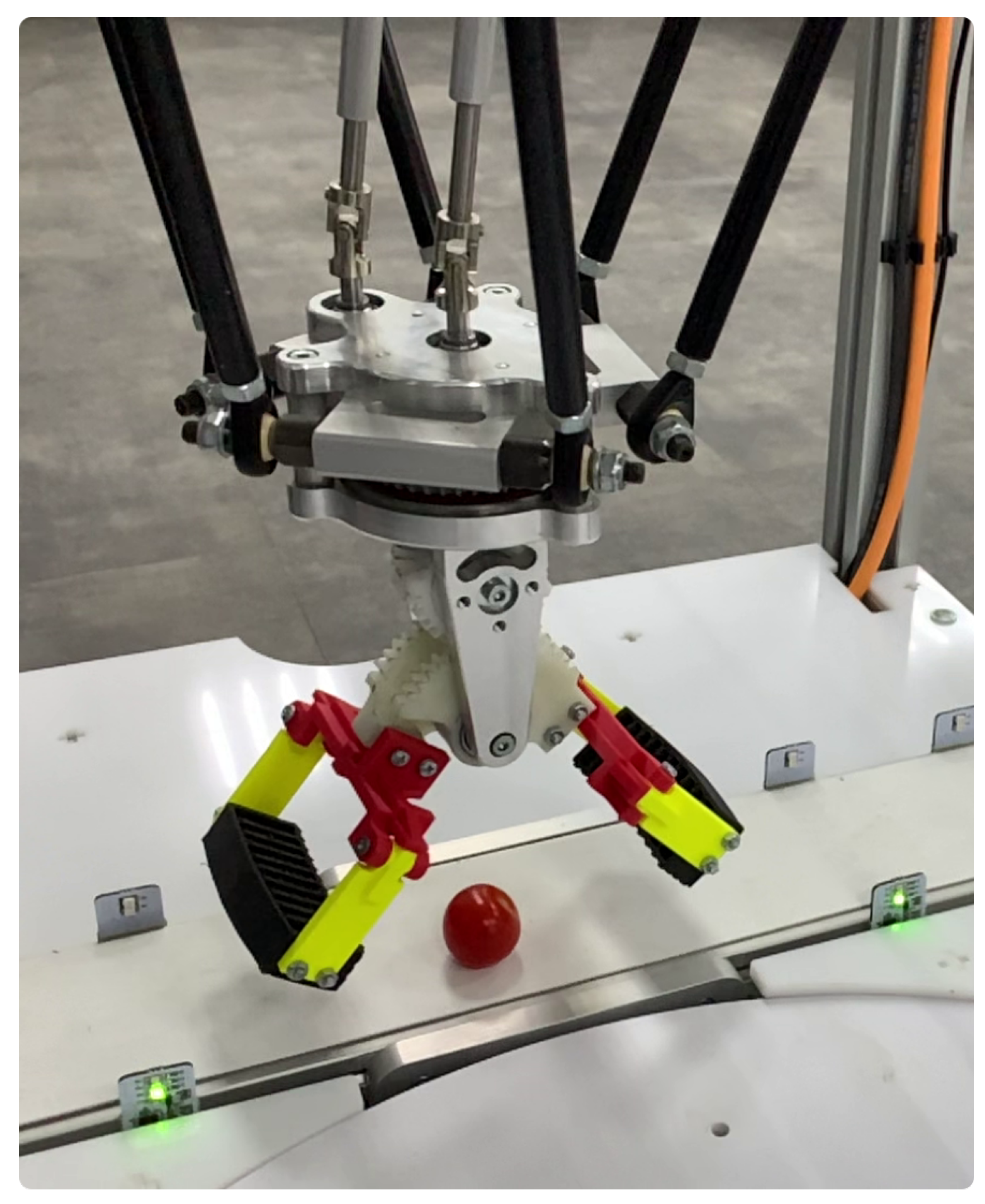
Finally, it was decided to implement the first version (v.1) of the gripper, equipped with two B&R 8LVA23.R0015 motors. The gripper frame was made from aluminum, while the gears were created from polyacetal. All aluminum and polyacetal parts of the gripper was manufactured by using CNC milling. In the prototype, a 3D printed fingers were used. They consist of rubber pads made from REC Rubber and finger’s holders printed with PLA plastic. Rubber pads are connected to finger’s holders via rotational joints. These joints are designed to compensate changes in the distance between ends of rubber pads during grasping. The manufactured gripper is shown in
Figure 6.
The gripper has the following parameters: m, m, m, m, m, m, m, m, H, H, Ohm, Ohm, V/(rad/s), V/(rad/s), Nm/A, Nm/A, , and .
The Rotation and Grasping Force Controller was fully implemented onboard of the B&R 80VD100PD.C022-14 ACOPOS Servo Drive using its standard cascade controller, modified with Smart Process Technology blocks. Feed-forward channels between Grasping Force and Rotation axis were created using internal cross-communication interface of the drive. Finally, current control loop cycle length of 50
s, velocity control loop cycle length of 200
s and positioning control loop cycle length of 400
s were achieved. The gains of the Current controllers were chosen as:
V/A,
V/A,
s. The gains of the velocity and position controller were chosen as
As/rad and
1/s, respectively. Feed-forward differentiator time constant was set as
s. Feed-forward gains were evaluated according to (
9). Maximal angular velocity and acceleration, which determine the speed ramp, were set as
and
, respectively. Finally, the drive was integrated into the robot’s control system using Ethernet POWERLINK fieldbus.
Table 3 shows the comparison of the fingers linear speed between the proposed gripper and another industrial gripper of a comparable size. This speed is critical for the performance of Pick and Place operations as it directly determines fingers’ opening/closing time. Compared to electrical grippers, the proposed solution has a much higher speed coupled with lower mass installed on the robot’s flange (
Table 2). The only electrical gripper involved in the comparison that is lighter than our gripper was ABB SmartGripper, designed for YuMi robot, but at the same time its grasping force is more than two times lower than that of our model. It can also be seen that a fast pneumatic gripper outperforms all electrical ones both in terms of mass to peak grasping force ratio and the finger’s linear speed. Still it cannot provide any online force control, so it is not suitable for manipulating fragile objects.
Due to the ultra-low closing time, there is no practical reason to adapt the opening/closing angle for grasping objects of various sizes. It is an additional benefit of the proposed solution, as other electrical grippers may require such adoptions to achieve timing suitable for high-performance Pick and Place operation.
To perform the rest of the experimental studies, the gripper prototype was installed on DeltaCube (
https://delta-robot.ru/, accessed date: 23 November 2022) educational robot and integrated into its control system.
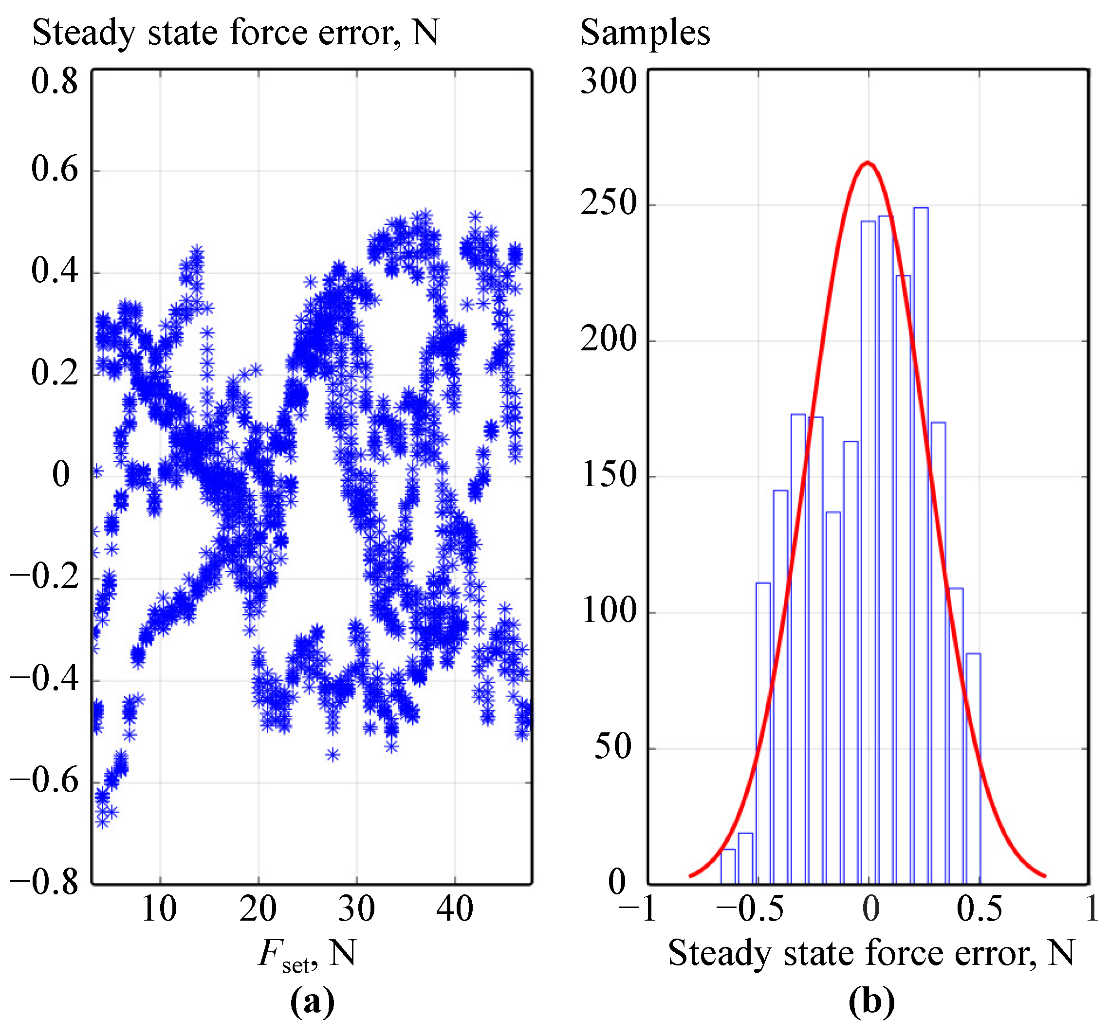
The accuracy analysis of the force control was verified using two different sensors. The steady state values of the grasping force were measured using B&R X20AI1744-3 module and a 10 kg range strain gauge mounted on the gripper’s fingers. This sensor was used to estimate dependency
and to inform Grasping force controller’s lookup table. Then to verify repeatability we performed 50 grasps for each
value from 3 N to 48 N range. The results are shown on
Figure 7a. As it can be seen, the steady state error never exceeds 0.8 N. Moreover, in most of the cases it was below 0.5 N (
Figure 7b).
As the X20AI1744-3 module, used in previous experiment, has 5 Hz input filter and is not suitable for dynamic measurements to estimate deviations of grasping force during highly accelerated rotations, we changed it to an additional B&R 8LVA13.R0015 motor, which was mounted on the axis of the Finger’s gear. It was controlled by a separate servo drive, configured to hold its position.
was estimated according to (
19).
where
is the quadrature current of the added motor and
is the its torque constant. Due to an additional inertia introduced by adding the motor, Rotation and Grasping force controller’s gains were adjusted to provide the same timings. The measurements using these sensors were performed only in the low part of the gripper’s force range, as the 8LVA13 motor has quite low a nominal torque. At the same time, more powerful motors will have a higher mass and impart more inertia that will critically limit range of possible acceleration.
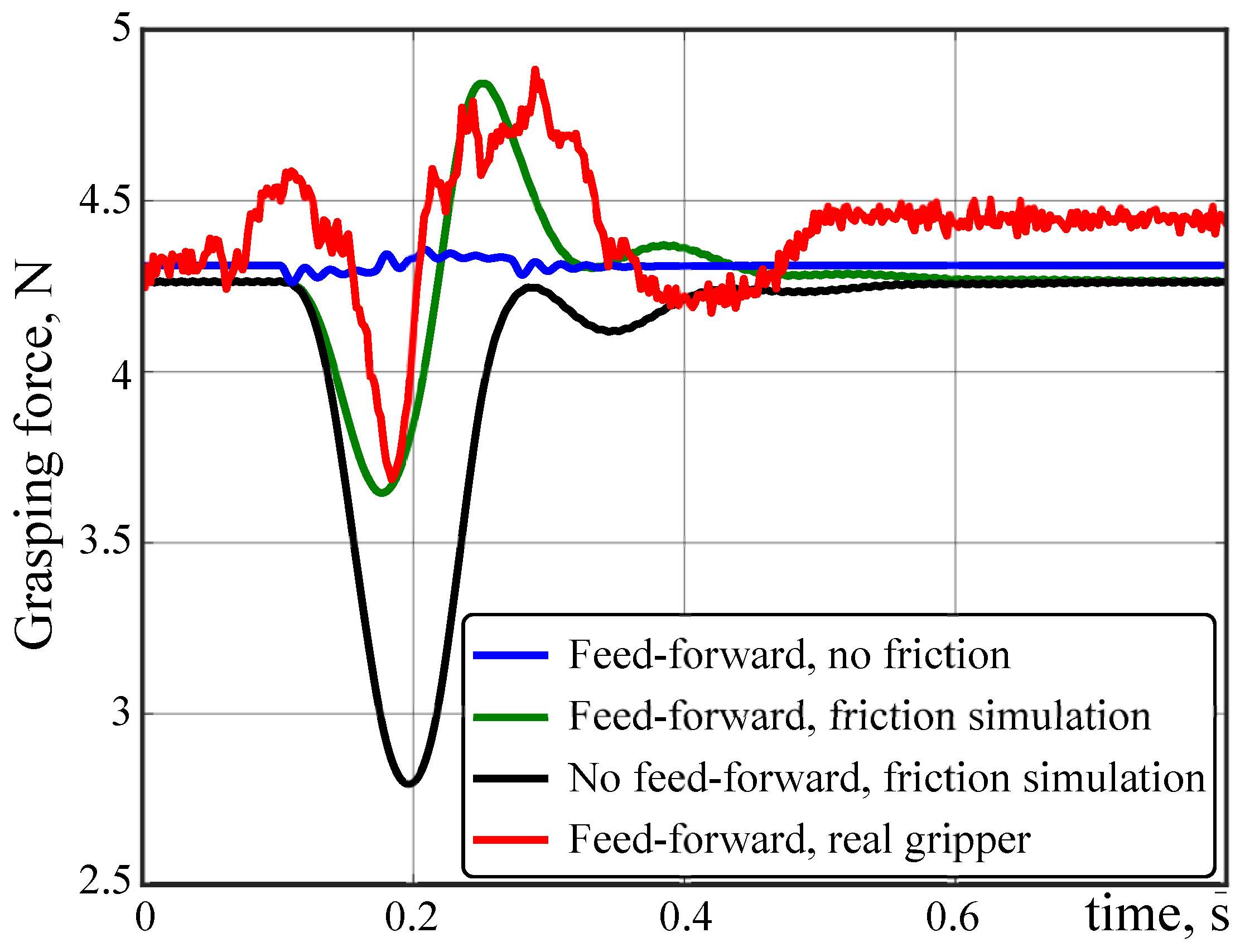
Before performing the experiment on the real gripper, the built prototype was simulated using SimInTech (
https://en.simintech.ru/, accessed date: 23 November 2022) software. First, we simulated ideal mechanics without friction. Then, we switched on friction simulation. Furthermore, for ease of comparison we performed additional experiment with no feed-forward (
and
). The grasping force set point
was constant during each rotation.
The actual grasping force
transient processes in all simulated cases are shown in
Figure 8. As it can be seen, force sag during rotation without the use of feed-forward channels reaches up to 35% of the set point. In the case of friction simulation, this sag can be decreased down to 15%, making grasping force control precision suitable for a wide range of industrial applications. In ideal case with no friction, force error can be minimized below 5% of the set point.
The simulated behavior matches the results acquired during the experiment with the real prototype both in term of the
transient process form and amplitude (
Figure 8, red line). The difference between the real and simulated grasping force steady state value, seen on
Figure 8 can be determined by the steady state grasping force error, which was measured in the previous experiment (
Figure 7). Most likely it is caused by friction in different parts of the gripper. The absence of this error in simulation can be explained by the simplicity of the used friction model. As it can be seen from the experimental data (
Figure 8) the steady state error is generally smaller than the peaks caused by highly accelerated rotations.
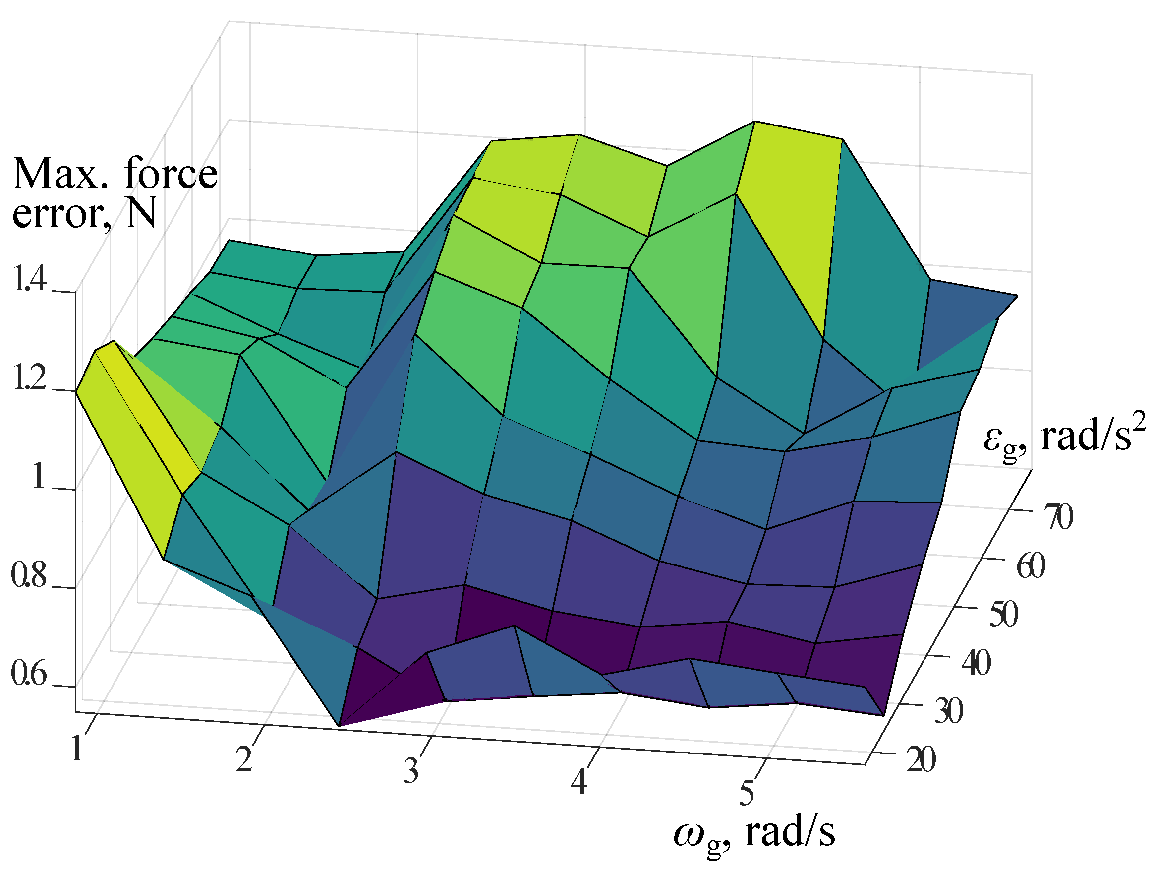
To analyze how force control precision depends on rotation parameters, we performed a series of experiments. During each experiment the grasping force was set as a constant value from the 3–5.7 N range, and then two
rotations were performed, in forward and backward directions. This range of grasping force was chosen to fit the torque measurement device’s capabilities. The parameters of these rotations were taken from the following ranges: velocity—from
to
; acceleration—from
to
. All measurements were made with the position of the grasping device at the same point in the robot’s working area. The position of the grasping device does not affect the measurement results in any way since the telescopic shafts transmit the moment equally efficiently throughout their entire operating range. During all the rotations, transient processes of grasping force error were recorded with 1 ms sample time. Those processes were then analyzed and a maximum grasping force error was evaluated for each pair of the rotation acceleration and velocity (
Figure 9). At any acceleration and velocity, the surface of maximum force error demonstrated in
Figure 9 never exceeds 1.27 N, which can be considered as the maximum error level for the developed prototype.
Table 4 compares this value to the force control error of competitive grippers. As it can be seen, the force control precision of the proposed solution is 2.3–23.2 times higher compared to similar industrial grippers available on the market (
Table 4). It should be mentioned that force errors for competitive grippers provided in
Table 4 were taken from their datasheets and represent the worst-case scenario for each gripper. Thus, those values are achieved at different grasping speeds. Still, according to
Table 3 and
Table 4, our design outperforms other compared electrical grippers not only in terms of force control precision but also in terms of finger speed.
If we analyze the dependency of the force error from rotation acceleration and velocity (
Figure 9), it can be seen that it reaches its maximum values while moving with medium and low velocities. Moreover, one of the surface peaks is near the point corresponding to the lowest acceleration and velocity. This can be explained by friction being the main source of the grasping force error. This hypothesis is also supported by previously obtained experimental results (
Figure 8). It is worth mentioning that real experimental results match simulated ones. The model used for simulation did not consider cardans’ backslashes and telescopic shafts torsion. Neither of these factors had any significant impact on the behavior of the real gripper during the last experimental series, which included more than 1500 consequent grasps and rotations. This supports the above statement that the proposed controller minimizes the influence of backslashes and shafts’ torsion. As a result, friction can be considered a critical factor in reducing grasping force precision, and its reduction is the primary goal of designing an industrial version of the proposed gripper.
The gripper’s performance in real Pick and Place operations performed on vulnerable soft objects was evaluated during the final experiment. The developed prototype, installed on the delta robot, was used to pick a cherry tomato, lift it, turn on 45°, put down, and release the tomato. This turn angle was chosen because in most of the industrial Pick and Place applications, the angle correction performed by a robot is below 45°. According to [
33] cherry tomatoes are damaged if squeezed with the force 15.2–23.8 N (depending on their variety). Thus, the grasping force should be at least 1.5 times lower than this limit to prevent damage. As our gripper has a force error of 1.27 N (
Table 4), the grasping force during the experiment was set to 8.2 N to guarantee the integrity of the manipulated tomato. The Pick and Place operation was recorded by a high-speed camera at 240 FPS. We performed a series of experiments on different tomatoes, and none of them were damaged. The average opening/closing time was 92 ms. The average time required to lift and rotate the tomato by 45° was 130 ms. As a result, the average overall time for Pick and Place operation was 314 ms, equaling 191 Pick and Place operation productivity. It is generally higher than the average rate of modern delta robots provided in [
7]. Thus, the proposed gripper design will not be the limiting factor for the overall performance. The Pick and Place operation performed on cherry tomato is demonstrated on the video attached to the paper as media data (
Video S1). For the demonstration purposes, the gripper on the attached video was rotated after the robot finished lifting and before it started moving, in deference to the described above experiment when those movements were performed simultaneously.
To the best of our knowledge, none of the currently developed grippers can provide such productivity at such low grasping force.
Table 5 compares our experimental results with the competitive solutions based on data from their datasheets. The closing time of ONROBOT force-controlled grippers significantly increases when low grasping force is applied and become 1.5–2 times worse than provided by our solution, even disregarding it was measured during only 8 mm fingers translation. SCHUNK EGS 25 cannot grasp with force below 15 N, which is unsuitable for operations with such vulnerable objects as cherry tomatoes. Furthermore, it has maximal fingers travel range of only 6 mm, while the diameter of the abovementioned cherry tomatoes may vary from 25 to 35 mm (considered optimal size) and may even be greater than 35 mm [
34]. Finally, compared to ABB SmartGripper, our solution has a much higher closing speed and better precision of force control (
Table 4).


