1. Introduction
To maintain the reputation for being the safest mode of transportation, the aviation industry indeed needs regulated, reliable, consecutive aircraft maintenance programs. In such programs, inspections and accurate damage evaluations of aircraft systems and components are essential. Non-destructive testing (NDT) methods are often used in such instances. These tests are used to evaluate the airframe and engine components for damages and damage initiations preserving the original structural properties. Amidst the main NDT methods, eddy current testing, ultrasonic testing, liquid penetration inspection (LPI), magnetic particle inspection (MPI), X-ray, and thermography are prominent [
1].
Present-day aircraft structures such as fuselage, wings, and flight control surfaces are made using composite structures, especially honeycomb composite because of their high strength-to-weight ratio and, corrosion resistivity properties. Common issues of the composite structures are debonding, delamination, cracks and dents, burns due to lightning strikes, and water ingressions are common among them [
2]. Amidst them, water ingression is the most critical and vulnerable, as it is damage that cannot be easily detected through visual examination or using quick conventional inspections. Though voids due to damages or caused during previous repairs, through loosened fasteners, and through cracks due to material failures, atmospheric water ingresses inside the honeycomb of the composite structure. This ingressed water, due to altitude changes during flights, thermally expands and contracts, inducing undesirable stresses in the structure causing debonding, delamination, and corrosion of the composite structure. Water ingression is also unfavorable for composite repair treatments such as composite curing [
3]. Inability to identify the water ingression and treat the issue on time could cause massive catastrophic failures. To detect water inside honeycomb structures, the non-destructive methods that can be used are tap testing, ultrasonic inspection, radiography, and thermography [
4]. Amidst these NDT methods, the recommended method in the aviation industry for water ingression detection is thermography [
5]. In the conventional method of thermography inspection, aircraft technicians perform the inspection using manually operated thermography cameras, by accessing the specific aircraft location using cranes and jigs. This conventional method has been identified as a risky, time-consuming, costly task that strictly depends on the skills and the experience of the performer. Thus, a method to inspect remotely with reasonable accuracy is important. This paper purposes a robotic platform to conduct such activities effectively.
To achieve the specific inspection task, the robot must be designed to safely access the inspection area and perform the inspection accurately by steadily remaining in the position. Two sound methods for access to different aircraft areas safely and performing inspections effectively is the use of either a drone or a wall-climbing robot that could climb the aircraft surface [
6]. The advanced computer integrated indoor inspection drone launched by Airbus in April 2018 [
7], for aircraft visual inspection to reduce inspection times and enhance report quality is such a pioneer industrial robot for inspection. Unlike a visual inspection, for thermography, throughout the inspection duration, stable positioning is a requirement [
8], which is difficult to achieve by controlling a drone at a fixed location. Thus, a wall-climbing robot that could firmly hold its position is more feasible for a thermography inspection process.
The paper will proceed first by giving a detailed description of the vehicle structure following the description of the ducted fan and robot maneuvering component design, under the robotic system design. Next, under the robotic system design, the electric and control system design and the thermography system design will be detailed. Under the testing and result evaluation, the performance of the vehicle as a wall-climber and a thermography inspector will be evaluated. Finally, the derived conclusions will be discussed.
2. Robotic System Design
2.1. Robotic System
A wall-climbing robot should have the ability to perform two main tasks which are a contrast to each other. First, it should have enough adhesive power to firmly attach itself to the climbing surface against gravity, and the second is the capability to maneuver along the surface to required locations without losing the grip. Selecting a proper traction method for a wall-climbing method is critical for the operation and specific for the application. The main adhesion mechanism for wall-climbing robots is; the suction mechanism which uses active or passive suction cups [
9,
10] to create a vacuum in between the wall surface and the robot such that pressure forces could withstand its weight. According to the literature, vacuum suction cups could supply the required suction force against the climbing surface. A wall climbing inspection robot with one suction cup was developed by Yanzheng Zhao, Zhuang Fu, Qixin Cao, and Yan Wang in 2004 to perform ultrasound inspections on cylindrical stainless-steel tanks and cleaning of high-rise building walls. Required stability was obtained using an air spring sealing mechanism and for the sealing loop, a synthetic rigidity formula was obtained [
11]. The wall-climbing robots employing a legged mechanism are ideal for complex geometrical surfaces. The speed and the weight of the robot are comparatively high. The control system is quite complicated due to various actuators and valves which are dedicated to complicated movements of the legs [
12]. Another surface climbing platform equipped with tracked wheels that are capable of carrying more load was implemented by Chang and Doyoung in 2018 [
13,
14]. A specially designed moving track along with a rotary valve is the key point of having a higher climbing load with fewer parts. In 2018, a research team from Nazarbayev University, Kazakhstan developed a multi-rotor that is capable of wall climbing [
15]. The drone could land on the wall’s surface in an inverted direction and supplies required thrust using four rotors. Four wheels are attached to the mainframe and have the ability to be controlled independently. The magnetic force mechanism, which is ideal for metal surfaces where electromagnets or permanent magnets are used as the traction force against gravity; the use of microscale to large gripper which can grip on to the surface against the gravitational force; electrostatic traction and vacuum fan suction [
16], which has the same effect has in the suction cup method, the only difference is the use of a ducted-fan [
17] to create the vacuum effect in between the wall surface and the robot. However, depending on the fan type, due to the high rotation speed of the ducted fan, the effect of the vacuum can be dominated by the thrust force that acts as downforce on the robot.
For the designed thermography inspection robot, considering protection of the composite surface of the aircraft, the traction methods that have direct contact and direct adhesion force exertion on the surface such as vacuum suction, electrostatic traction, and gripper were eliminated and the ducted fan method that could exert traction force by the combination of thrust force and the vacuum suction effect was implemented. For the maneuvering of the robot on the surface, six differential wheels are included. The robot onboard has a heat pump to stimulate the composite surface to an adequate temperature and an infrared sensor that could feed the real-time temperature data via Bluetooth serial communication to a remote computer system where the temperature readings are processed into a thermal image and evaluated to determine the defect. The control system incorporates a hierarchical control architecture to establish an effective relationship between each hardware and software layer.
2.2. Functions
To achieve the performance as expected, the robot platform should have the capability to:
- (1).
Access the inspected area
The approaching mechanism is wall climbing, by being attached to the structural wall using the combined vacuum force and downward trust generated by two ducted fans. Six wheels will be used to locomote to the area of interest, on the structure. Two ducted fans can be tilted within a given selected range and speed will be controlled to find the adequate contraction force and forward force.
- (2).
Thermal stimulation of the structure
A commercially available heat pump was modified to be operated from 22.2 V to heat the surface of the composite to a suitable observable temperature.
- (3).
Perform the thermography inspection
Arduino-based AMG8833 thermal sensor was used to perform the thermography inspection and sent the data to be processed to the ground control unit.
2.3. Vehicle Structure Design
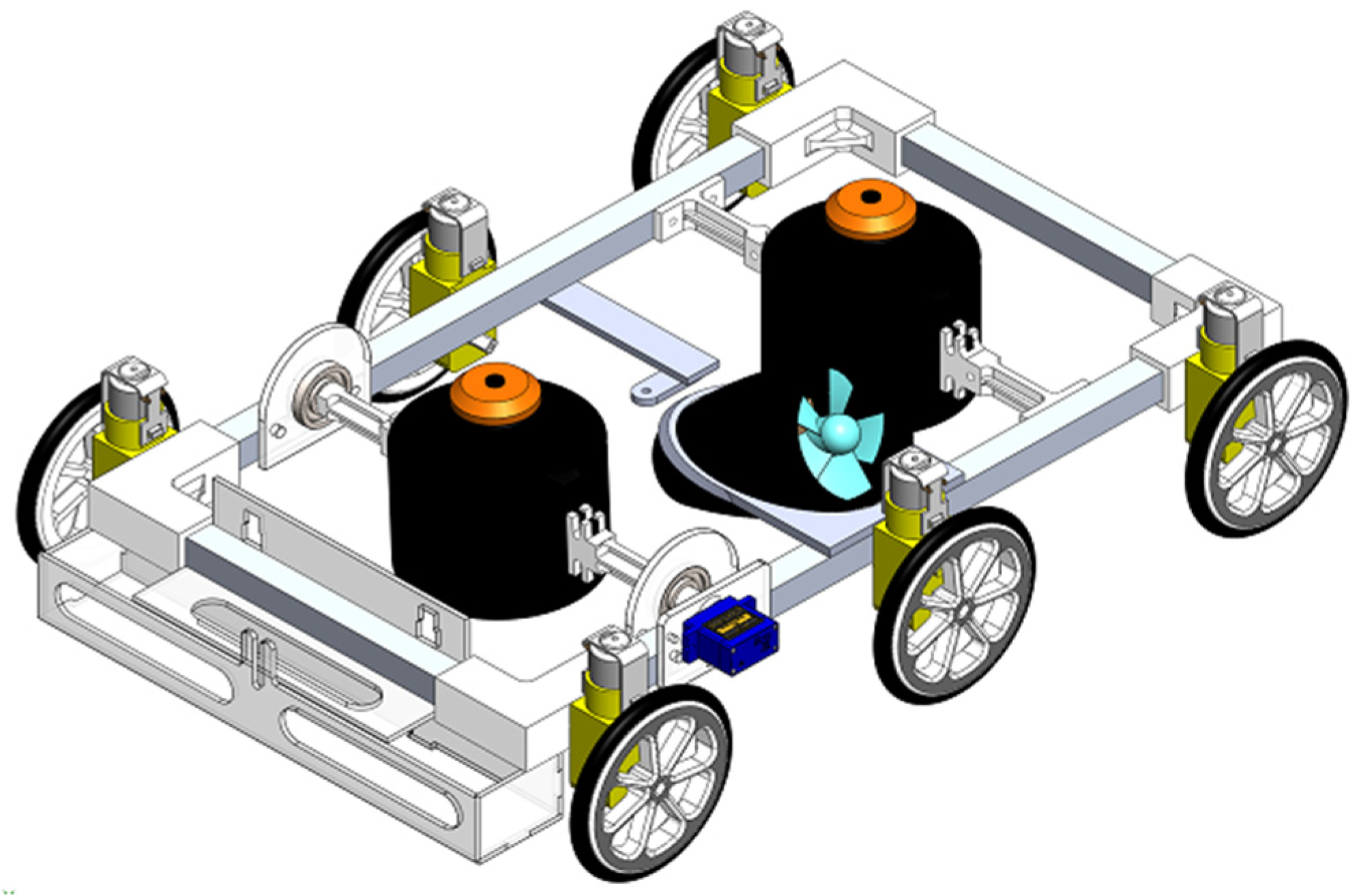
Figure 1 depicts the placing of each component in the designed 3D model.
- (1).
Frame
Several structural configurations were considered at the initial frame design phase. Amidst the applicable methods was the use of Perspex plates, steel beams, and Aluminum beams. Aluminum beams were selected due to the high strength to weight ratio. (Density-2.71 gcm
−3/Tensile strength-276 MPa). The box beam structure was selected due to the higher torsional rigidity [
18].
- (2).
Ducted Fan Assembly Mounts
The two electric ducted fans (EDF) are mounted in two separate methods to obtain the maneuverability and controllability of the platform. One ducted fan mount is a fixed one and the other one is rotating to provide the tilting feasibility to the bottom EDF. Both the mounts were made using additive manufacturing and the material was selected as ABS due to the thermal stability. The rotating mount was designed with a circular keyway at its end to maintain the required grip between the mount and the output shaft of the servo motor.
- (3).
Bearing Assembly
As one EDF is fixed with the feasibility to rotate, two bearings should be employed to reduce frictional losses and provide smooth rotation.
- (4).
Ducted Fan and Maneuvering Component
Two identical electric ducted fans (EDF) were used to generate the normal reaction to generate friction force between the vertical wall and the wheel surface for maneuvering and maintaining the equilibrium of the robot. The selection was made due to higher efficiency and low noise than the conventional propeller-type thrust generators.
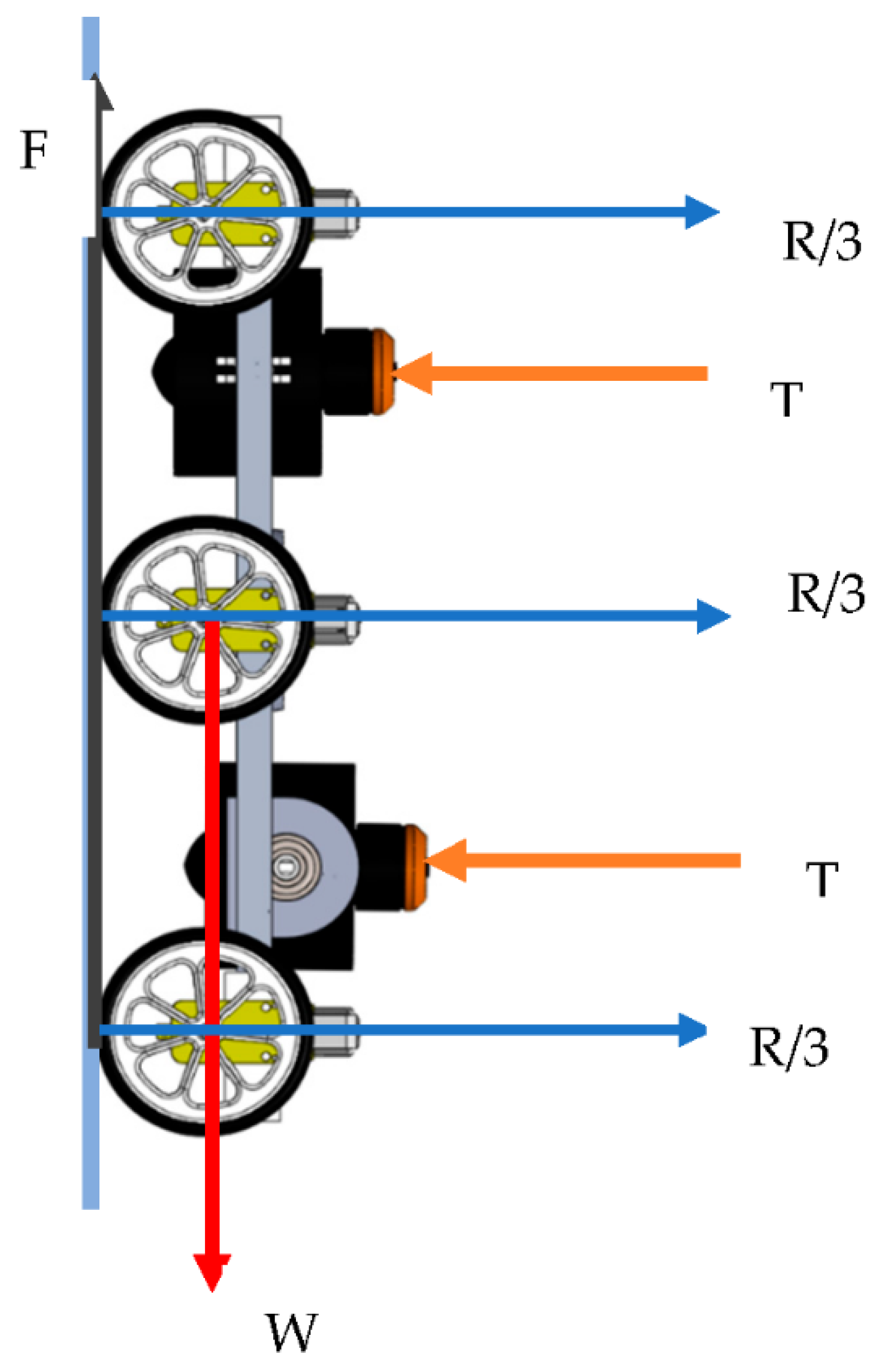
The required thrust from a single EDF was 18.86 N with a total weight of 25 N. The contact surfaces were rubber for robot wheels and glass fiber for the aircraft fuselage panels. The friction coefficient of contacting surfaces of 0.65 was obtained using both experimental and literature surveying methods. By using
Figure 2, the calculation is carried out.
Table 1 shows the weight of each component of the robotic platform.
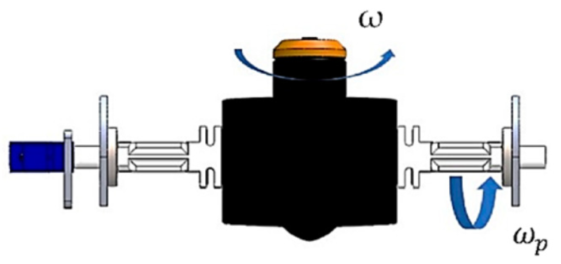
Figure 3 depicts the applied forces on the tilting EDF. The required torque for tilting the bottom EDF, while it rotates at its highest speed, was calculated using:
According to Equation (1), the required torque was 0.09 Nm and the 9 g metal gear servo was enough to supply the torque.
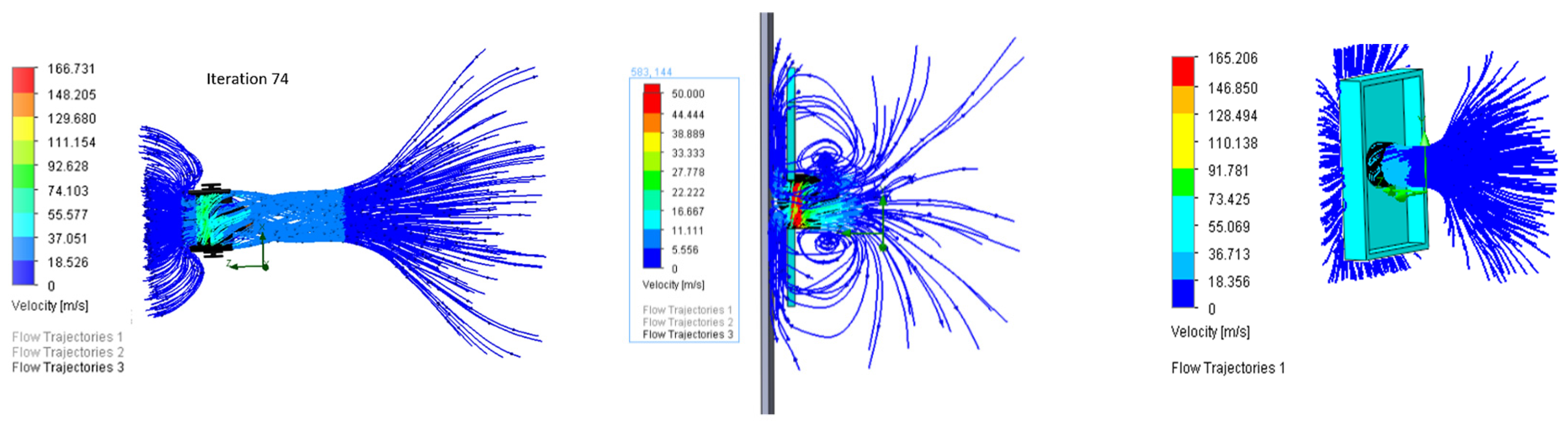
Several flow simulations were completed in order to identify the effectiveness of the back wall and the inner core shape.
Figure 4 shows the back wall with an inner core shape reduces turbulence and the pressure difference becomes effective apart from the thrust in wall climbing.
2.4. Driving Motor System
Six identical micro 6 v, 160 rpm, 120:1 dc geared motor was selected as driving motors for the locomotion of the robot. The required torque from one motor was 0.068 Nm at 160 rpm. The differential steering system was used for the maneuvering of the robot.
2.5. Electrical and Control System Design
- (1).
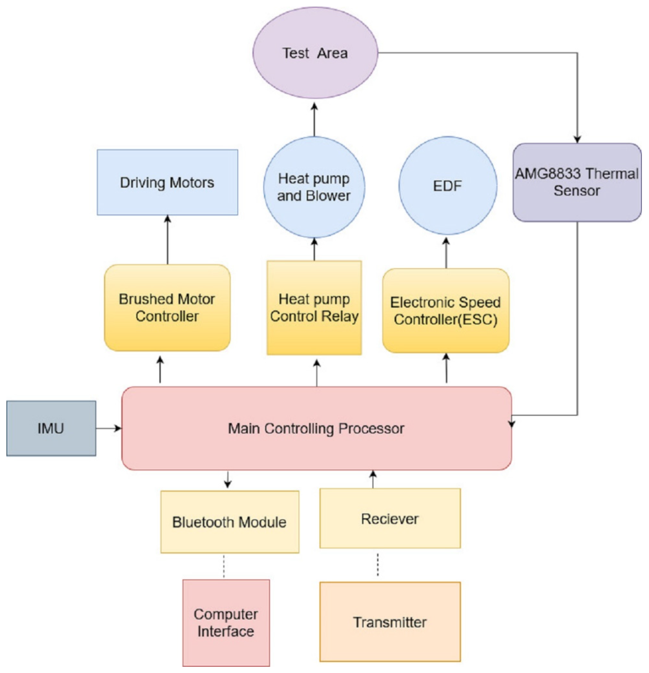
Overview
Figure 5 depicts the schematic of the control systems of the platform.
- (2).
Tilting control
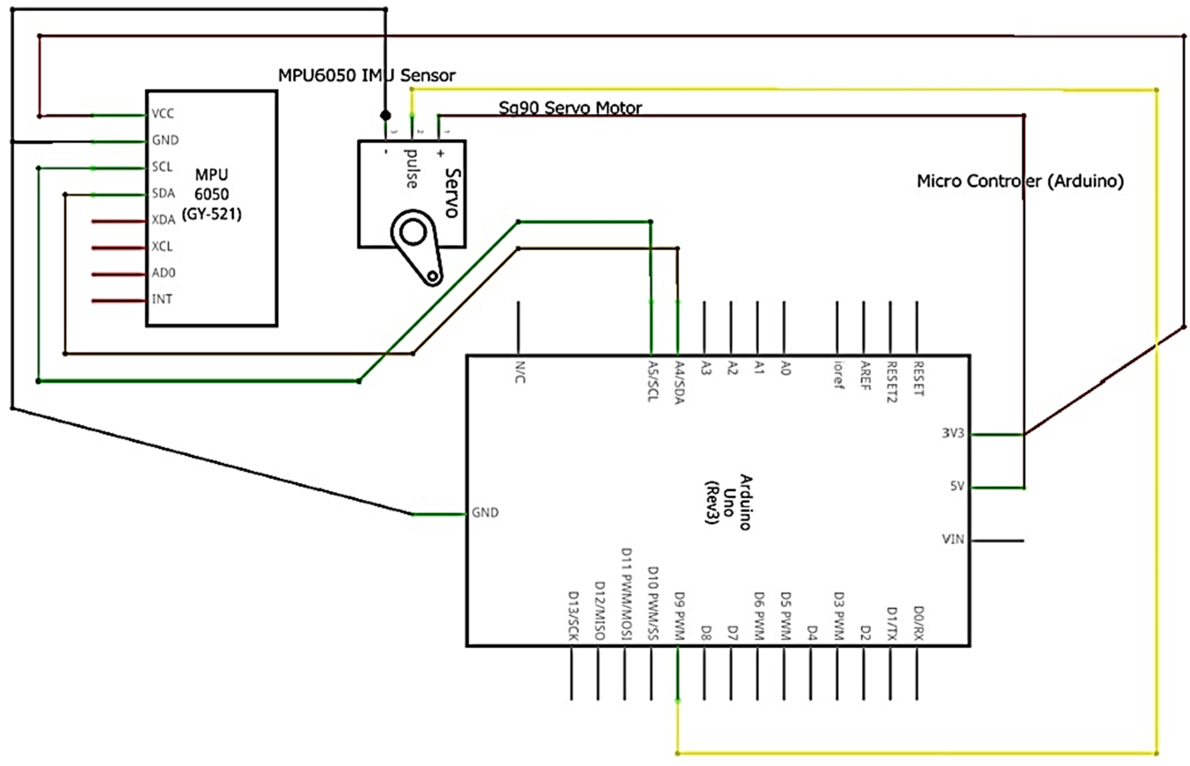
An MPU6050 (
Figure 6) inertial measuring unit was used to measure the inclination of the robot and outputs were processed in an Arduino Uno to send outputs to the tilting control servo to maintain the required inclination of the bottom EDF.
- (3).
Power supply
The main power-consuming units are ducted fans, heat pumps, and driving motors. Two lithium-polymer batteries are used in the series to power both ducted fans. Therefore, the required minimum input voltage was set to 22.2 V. The battery power was distributed through DC-DC step-down circuits since components are operating with different input voltages. The capacity of the battery is one of the most important things in battery selection, as it decides the durability and the power to weight ratio of the robot. Using experimental data and calculations, choose a battery pack with minimum weight and maximum durability. The theoretical total power consumption of the robot while the inspection was 3.4 KW and two identical three-cell lithium-polymer batteries, which have a capacity of 1500 mAh were selected as the main battery unit and durability was limited to 37.5 s.
Table 2 shows rated input voltages and how each component contributes to total power consumption.
2.6. Thermography System Design
- (1).
Technique selection
Among the available thermography techniques, passive thermography, active thermography, flash thermography, and Vibro thermography, the active thermography technique was selected to perform in the project. The main reason for the selection is that the active thermography method is the recommended NDT inspection method for detecting water ingression in composite structures in aircraft maintenance [
19]. Apart from that, active thermography can create a perfect heat distribution in the component even in a non-operating condition, and as the design is focused to conduct as an enhancement platform for scheduled inspections, using an active thermography method is necessary. In addition, rather than just after the operation inspection, here, a controlled heat distribution can be obtained for the inspection.
- (2).
Infrared Array Sensor Grid-Eye (AMG8833)
The AMG8833 sensor grid was selected instead of a thermography camera. This high-precision infrared array sensor based on advanced MEMS technology consists of 64 IR sensors in a two-dimensional area of an 8 × 8 grid. The module is compatible with I2C communication, which allows direct access to each sensor. The sensor has the properties shown in
Table 3 that make it possible to be applied instead of a camera.
- (3).
Thermal Imaging System
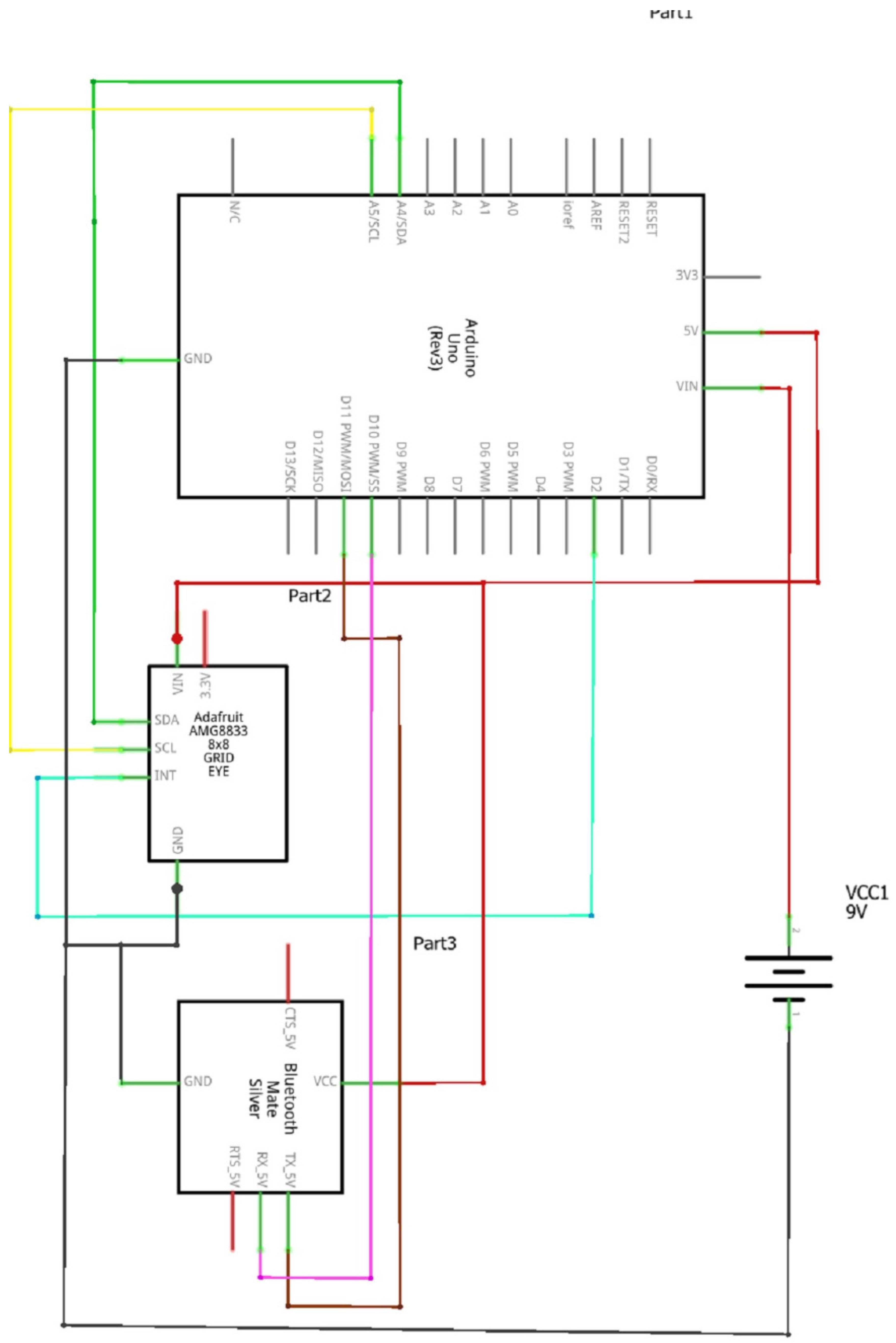
The thermal imaging system (
Figure 7) consists of a heating pump, IR thermal array grid-eye sensor, HC-05 Bluetooth module, Arduino, and a GUI computer interface with image streaming and image processing customized programs. Each part of the system performs dedicated tasks as follows:
Heating pump: stimulates the concerning inspection area for the active thermography inspection, creating an adequate thermal distribution over the inspection surface.
IR thermal array grid-eye sensor: measures the real-time temperature over the inspection area in the form of an 8 × 8 array grid giving 64 temperature values.
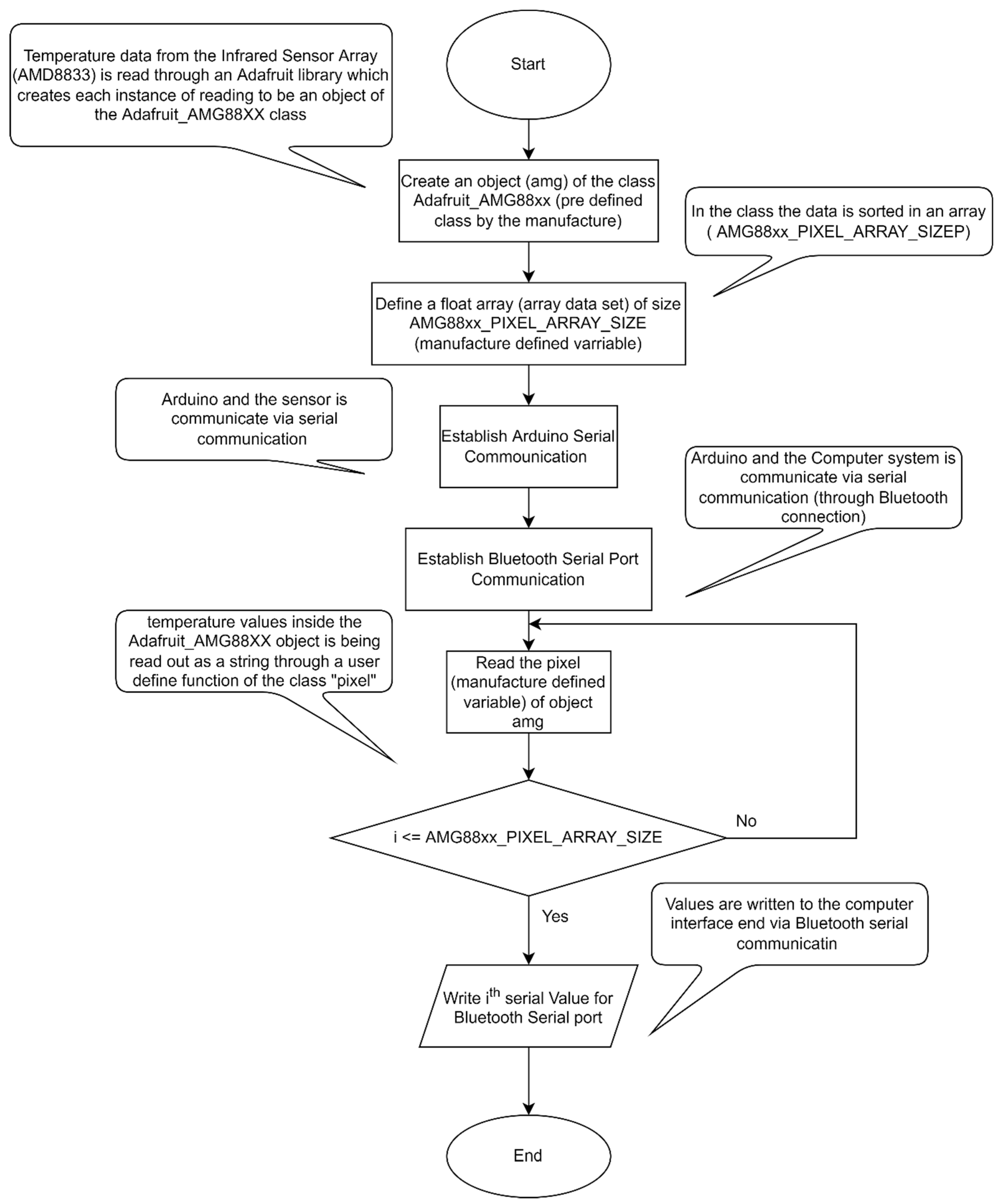
Arduino microcontroller board: communicate with the IR thermal array through I2C interface and serial communication with GUI computer interface via Bluetooth. Following the Arduino code onboard, through I2C communication it accesses the thermal sensor addresses to obtain the real-time corresponding stored temperature values, and converts the read PWM values into temperature values, which will next be conveyed to the computer system via Bluetooth.
Bluetooth module: establish the real-time serial communication between the Arduino board and the GUI computer interface.
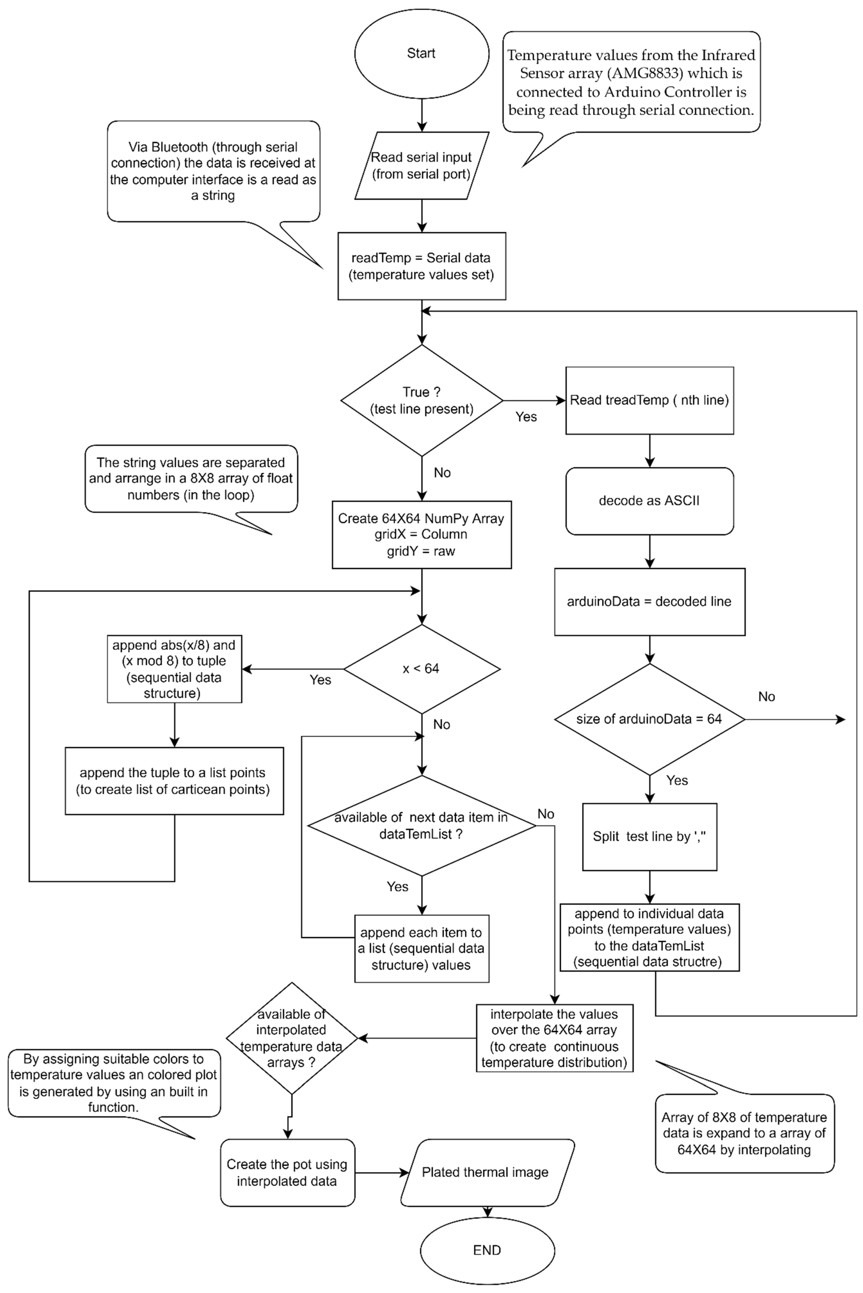
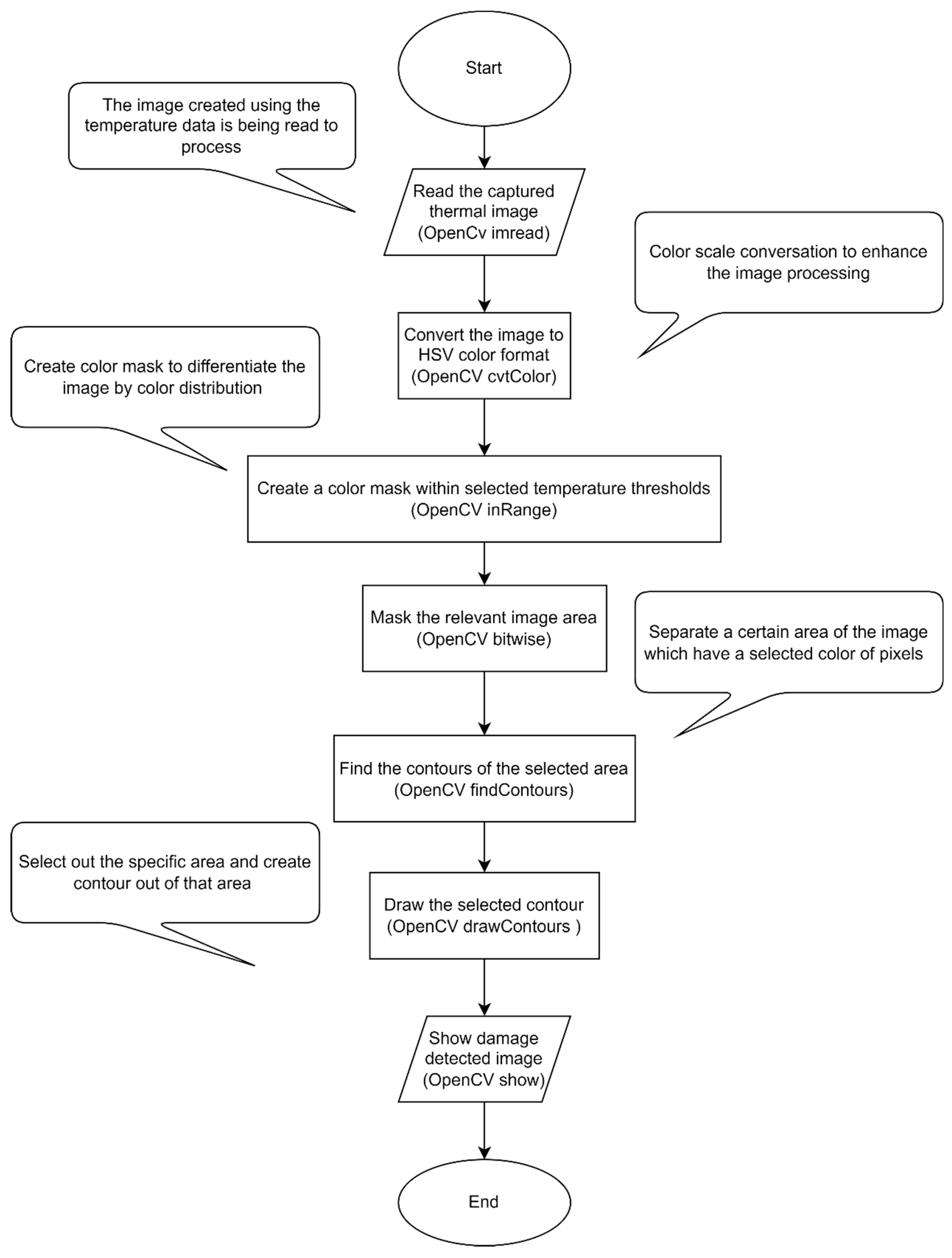
GUI Computer interface: through the Bluetooth serial communication it receives real-time thermal data, which will be used to create thermal images by interpolating the thermal values into a high-resolution grid of 64 × 64, using the customized python program. These images will be saved as required for further image processing to determine the defective area.
The thermal imaging system, integrated into the robotic platform, can scan through the inspecting area when the robotic platform maneuver across the inspection area, and feed real-time thermal data to the GUI computer via Bluetooth. This data will immediately create a real-time image (plot a heat map that can be manipulated as an image) depicting the real-time thermal variations. The program has the provisions to save important image instances for post-processes to determine the defected (water ingression) area. For this thermal data collection, thermal data communication, thermal image generation, and defect detection, there are three separate programs, one for the Arduino control, and the other two python computer programs for image generation (
Figure 8) and image processing for defect detection (
Figure 9 and
Figure 10).
3. Testing and Results Evaluation
3.1. Vehicle Performance Testing
The robotic platform should possess the ability to wall climb. In the testing of the maneuvering, two stages were the main focus: the steering of the platform and the method of retaining vertically. In the design phase, the clarification for applying six wheels to obtain more friction force is discussed. With six wheels the maneuvering is completed, and separate testing was performed for the maneuvering by moving on a horizontal surface.
The thrust force of two EDFs provides the force to overcome the momentum. The fixed EDF location was altered in each testing scenario. At first, only one ducted fan was used. Even though the prototype is comparatively smaller, the thrust force was not enough to hold the platform vertically on the wall. The turning point of the wall climbing is the application of a bottom surface to the platform. Thus, apart from the thrust force, the pressure difference contributes to resisting the momentum and it led to successful wall climbing in the second prototype.
The next phase was to increase the ability to sustain more weight as the final weight estimation is higher. So, two EDFs were mounted to obtain additional thrust force. There are two prime expectations from the application of two ducted fans.
To obtain more thrust force to overcome the increased momentum due to weight.
To obtain a component of thrust force from an EDF to obtain additional support for climbing.
The bottom EDF is selected to be the tilting EDF as the tilting reduces the horizontal thrust component which helps to overcome the momentum. As the ducted fans were moved to the two extents the pressure force is somewhat reduced. The vertical component of the thrust force is required in ascending to support the driving motor wheel assembly. In descending, the component is used to minimize the slippage of the wheels and to hold the position.
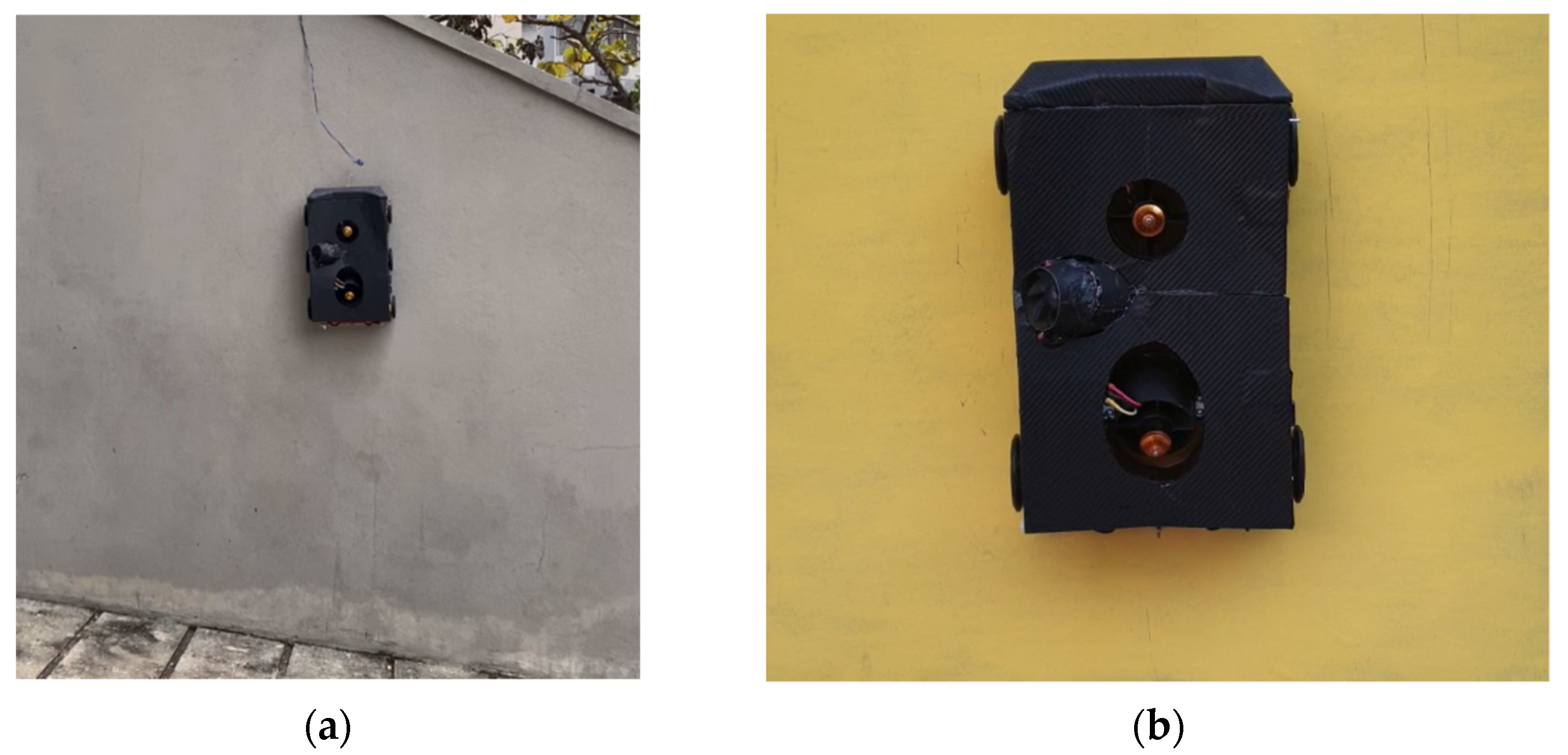
The next modification is to make the tilting mechanism of the EDF autonomous with an inertial measurement unit (IMU). Although automation was completed, the vibrations of the platform led to a critical issue. Since the MEMS IMU is sensitive to vibrations, with the increment of the throttle, the tilting EDF loses its location holding capability leading the EDF to rotate back to the initial angle. For that, a damping system should be introduced. The system was modified with the ability to both autonomous tilting and manual tilting with the feasibility to override the autonomous location. During the initial testing, a safety hook was used to avoid any damage to the robot. Initially, the robot was tested using a vertical cement wall which has a higher frictional coefficient in order to avoid any damage during the very first testing (
Figure 11a). Then the robot was tested with a vertical composite wall to check its maneuverability in real industrial applications (
Figure 11b).
3.2. Thermography Testing
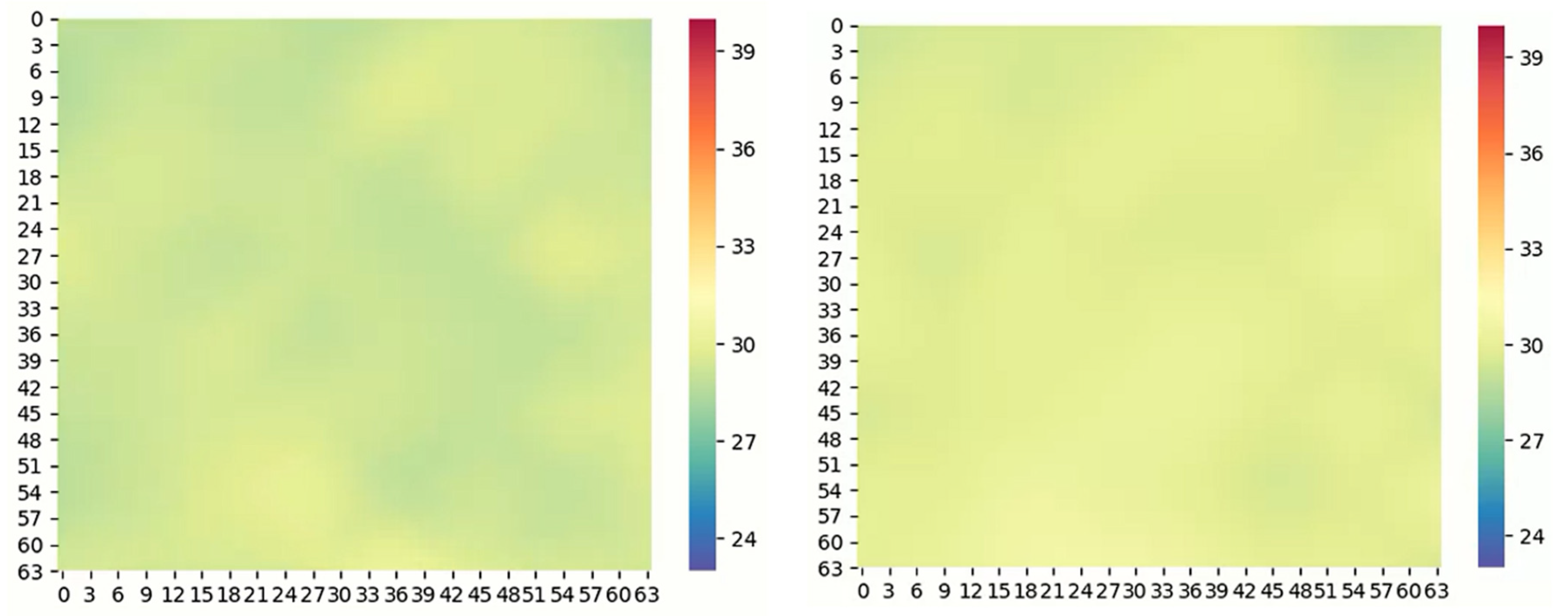
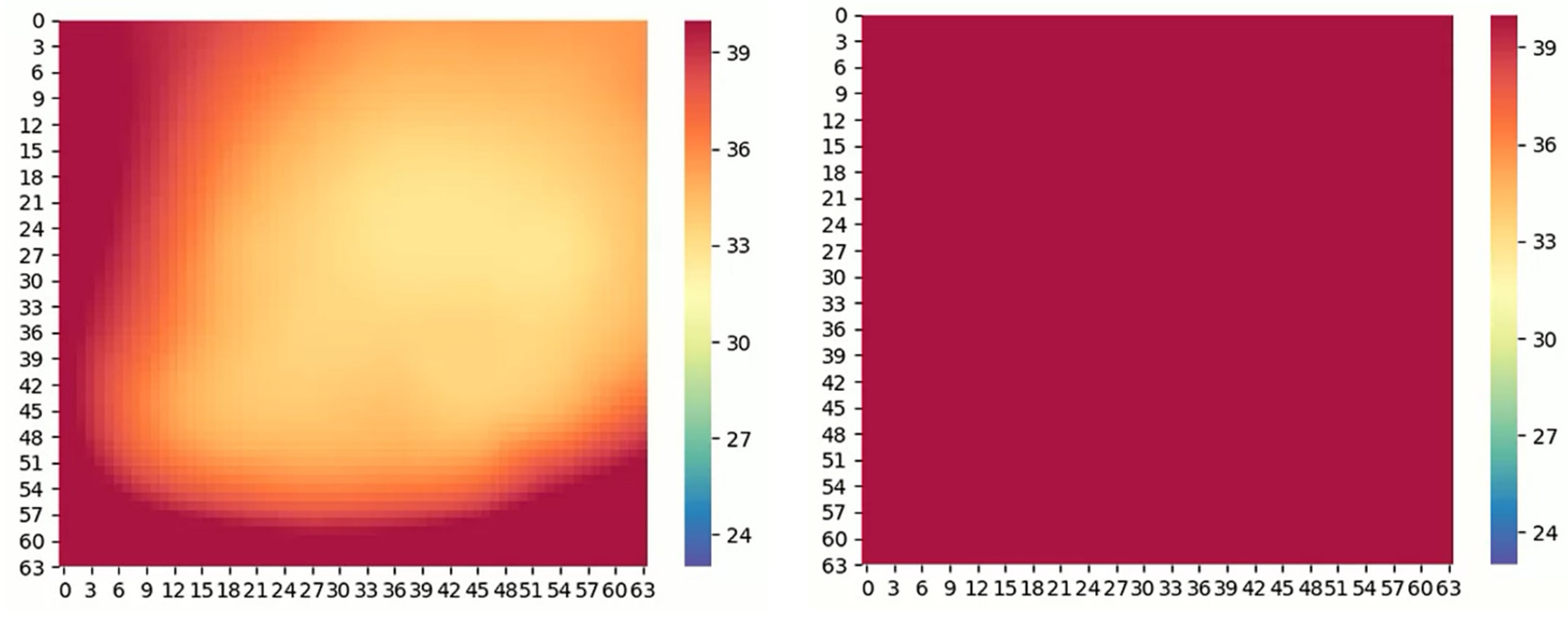
At the initial phases of the thermographic testing, the level of expectation of the process to identify the presence of water was studied. Amidst the undergone problems, the cost of the industrially recommended camera was prime. Due to the limitations, AMG8833 was selected as the sensor to replace the thermographic camera. In the testing phase, the resolution of the sensor was not sufficient to obtain an image with high contrast to identify the area with water clearly. The 8 × 8 arrays of infrared sensors provide 64 temperature values, which were then subjected to interpolation and color assignment to obtain a more detailed image. A resistive element-based heat coil along with a blower fan was used to heat up the inspection area. The heating power was set to 500 W and the heating area was 450 mm2. To avoid heating up the thermography sensor, the heat pump was assembled at an angle of 25 degrees. The thermography sensor is located inside the polystyrene cover to avoid heating up the sensor and to maintain the required distance of 35 mm from the inspection surface.
The testing was carried out in different manners to identify a better method. In one method, the image was obtained with no means of heating. There, the identification of areas with water was comparatively difficult, as the temperature variation is little. In comparison, the left image always stands for the area with water and the right one is for the area without water in
Figure 12.
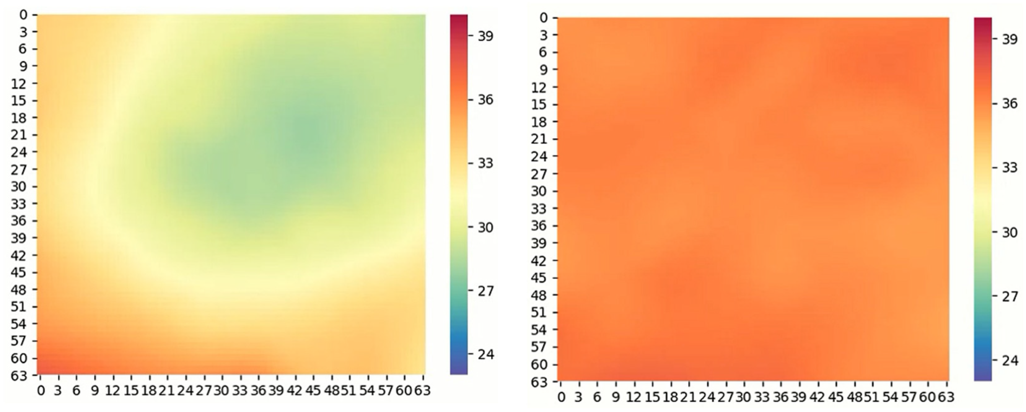
In the next method depicted in
Figure 13, images were obtained while heating. In this case, the variation is more, and better identification could be obtained.
The most successful method among the tested methods was to obtain an image while cooling (
Figure 14). Here, the heating is performed for a small-time interval, and the imaging is done while cooling. The contrast of the image is higher as the honeycomb has a higher heat diffusion rate than water.
By limiting the time of heating, the water is not heated while the metal structure heats more. This is the theory behind the successful identification of water ingression using thermography.
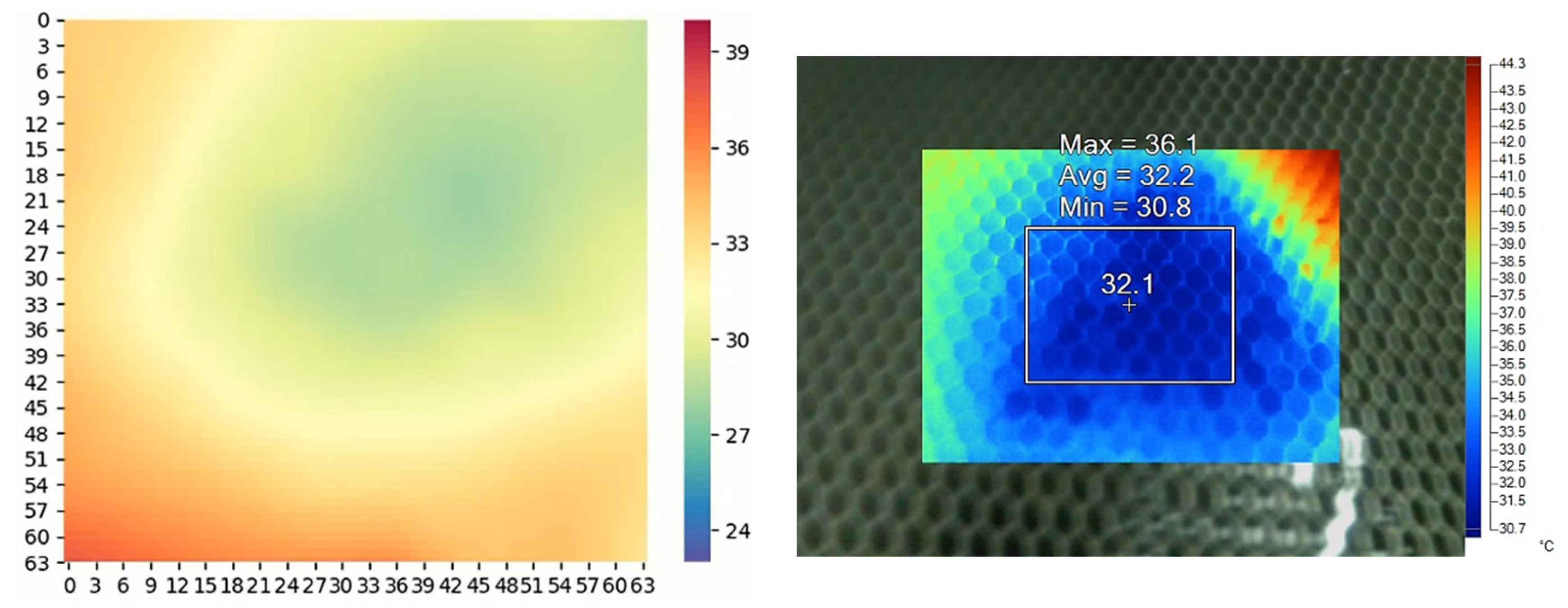
The validation of the obtained results is prepared using the Fluke Ti400 thermal imaging camera. The comparison of results obtained using the AMG8833 and the Fluke Ti400 are as follows. The left image is the one developed from the sensor data and the right side is from the camera in
Figure 15.
For the considered inspection area, the required heating time is 30 s and the cooling time is 20 s. The maximum average temperature of the area was 78 °C. For the area of 45 mm2 with the calculated power consumption of 500 W. As depicted, the accuracy of both methods is almost the same where the measured temperature of the water is about 28 °C and according to the sensor data, it was 30 °C. The interest is not subjected to the exact value of the temperature while there is a contrast between areas where there is water and where there is no water. Therefore, the applied method can be identified as sound enough for the identification of water ingression.
4. Conclusions and Recommendations
The aim of this research project is to initiate the use of autonomous platforms to carry out special tasks in the aviation industry to minimize human effort and risk, save time and increase accuracy. In this project, water ingression into composite structures was addressed, since currently the inspection is performed completely manually. Among the various NDT inspection methods, the thermographic inspection method is concluded to suit more for the inspection of water ingression in honeycomb structures. For that, the AMG-8833 sensor is used to obtain a real-time thermal image instead of industrially using thermal cameras. The suitable location and angle for the sensor to meet accurate industrial standards were obtained. The validation of the results and the comparison of the obtained results with the industrial thermal camera are carried out in the testing phase. Through the comparison of the results of both methods, it can be concluded that the selected scenario is feasible to a reasonable extent.
With the obtained results of the thermography, the following conclusion was made. The three phases of obtaining the image are without heat addition, while heating, and while cooling was carried out. Amidst these two methods, the suitable method is to obtain the image while cooling as it provides an image with more contrast.
The approach is studied using various mechanisms and the finalized technique is to use two ducted fans having one ducted fan feasible of tilting. The main aim of the ducted fan is to provide the thrust force to be attached to the wall while providing additional force to the driving force which acts against weight while climbing the wall. Wheels were designed in order to provide the required friction force for operation. By implementing the autonomous tilting mechanism with the help of IMU, power consumption can be reduced. Due to the vibrations, the MEMS IMU causes the servo motor to be inappropriate for the holding of a certain angle. So, either a suspension system needs to be developed for the IMU, or a manual control overriding the autonomous control needs to be used.
5. Future Developments
Considering the robotic platform itself and its performance in a real industrial environment (an aircraft MRO environment), there are provisions for future development to make the robot more reliable, efficient, effective, and friendlier to the industry. Thus, the future works would include developments for:
Fully automated localization, path planning, and navigation in a given industrial application environment;
Robust GUI interface, networked with the platform to control and observe the real-time performance, and inspection tasks;
Inclusions to ensure safe and reliable performance of the robot while complying with aviation safety requirements and regulations;
Enhanced operating time.
Author Contributions
The contribution of each author is mentioned here. Conceptualization, A.I.S. and N.P.; methodology, A.I.S. and D.S.C.; software, A.I.W.; validation, B.S.K., V.P.V. and A.I.S.; formal analysis, A.I.W.; investigation B.S.K.; resources, N.P.; data curation, V.P.V.; writing—original draft preparation, A.I.S. and N.P.; writing—review and editing, B.S.K., V.P.V.; visualization, A.I.W.; supervision, D.S.C.; project administration, A.I.S.; funding acquisition, N.P. All authors have read and agreed to the published version of the manuscript.
Funding
This research received no external funding.
Institutional Review Board Statement
Not applicable.
Informed Consent Statement
Informed consent was obtained from all subjects involved in the study.
Data Availability Statement
The study did not report any data.
Acknowledgments
The Sri Lankan Airlines, who supported us, and the Sri Lankan Airforce who motivated us for the project earn our appreciation.
Conflicts of Interest
The authors declare no conflict of interest.
References
- Towsyfyan, H.; Ander, B.; Richard, B.; Thomas, B. Successes and challenges in non-destructive testing of aircraft composite structures. Chin. J. Aeronaut. 2020, 33, 771–791. [Google Scholar] [CrossRef]
- Fernandez, F.; Rui, K.K.; Jeffrey, R. Design of a system for Aircraft Fuselage Inspection. In Proceedings of the 2016 IEEE Systems and Information Engineering Design Symposium (SIEDS), Charlottesville, VA, USA, 29 April 2016; pp. 283–288. [Google Scholar]
- Giguere, J. Damage Mechanisms and Non-Destructive Testing in the Case of Water Ingress in CF-18 Flight Control Surfaces, Defence and Civil Inst of Environmentalmedicine Downsview (Ontario), August 2000. DCIEM TM 2000-098. Available online: https://apps.dtic.mil/sti/pdfs/ADA388125.pdf (accessed on 1 March 2022).
- David, K. Nondestructive Inspection of Composite Structures: Methods and Practice. In Proceedings of the 17th World Conference on Nondestructive Testing, Shanghai, China, 25–28 October 2008. [Google Scholar]
- Heida, J.H.; Platenkamp, D.J. Evaluation of Non-Destructive Inspection Methods for Composite Aerospace Structures; National Aerospace Laboratory NLR: Marknesse, The Netherlands, 2011. [Google Scholar]
- Michael, K.K.; Wolfgang, O. Mobile shearography system for the inspection of aircraft and automotive components. Opt. Eng. 2003, 42, 1188–1196. [Google Scholar]
- Martin, F.; Cox, B. Airbus Launches Advanced Indoor Inspection Drone to Reduce Aircraft Inspection Times and Enhance Report Quality. Available online: https://www.airbus.com/sites/g/files/jlcbta136/files/47486f8e9506f5037381e4de90ade1ae_E-Airbus-launches-advanced-indoor-inspection-drone.pdf (accessed on 3 June 2020).
- Štumper, M.; Kraus, J. Thermal Imaging in Aviation. MA-Mag. Aviat. Dev. 2015, 3, 13. [Google Scholar] [CrossRef] [Green Version]
- Quan, Z.; Zhao, Y.; Fu, Z. Development of wall climbing robots with sliding suction cups. In Proceedings of the IEEE/RSJ International Conference on Inteligent Robots and Systems, Beijing, China, 9–15 October 2006. [Google Scholar]
- Hossain, R.; Ahmed, N. Design and Implementation of a Wall Climbing Robot. Int. J. Comput. Appl. 2018, 179, 13. [Google Scholar] [CrossRef]
- Zhao, Y.; Fu, Z.; Cao, Q.; Wang, Y. Development and applications of wall-climbing robots with a single suction cup. Robotica 2004, 22, 643–648. [Google Scholar] [CrossRef]
- Choi, H.J.P.; Kang, T. A self contained wall climbing robot with close linked mechanism. J. Mech. Sci. Technol. 2004, 18, 573–581. [Google Scholar]
- Zhu, J.; Sun, D. Development of tracked climbing robot. Intel. Robot. Syst. 2002, 35, 427–443. [Google Scholar] [CrossRef]
- Kim, H.; Kim, D.; Yang, H.; Lee, K.; Seo, K.; Chang, D.; Kim, J. Development of a wall-climbing robot using a tracked wheel mechanism. J. Mech. Sci. Technol. 2018, 22, 1490–1498. [Google Scholar] [CrossRef]
- Ali, H.; Zharakhmet, T.; Atykhan, M. Development of a Robot for Boiler Tube Inspection; School of Engineering, Nazarbayev University: Astana, Kazakhstan, 2018. [Google Scholar]
- Vasile, P.; Mircea, B.; Ionică, C. Flying wing with Electric Ducted Fan (EDF) propulsion. Appl. Mech. Mater. 2015, 811, 157–161. [Google Scholar]
- Sekhar, P.; Bhooshan, R.S. Duct Fan Based Wall Climbing Robot for Concrete Surface Crack Inspection. In Proceedings of the 2014 Annual IEEE India Conference (INDICON), Pune, India, 11–13 December 2014. [Google Scholar]
- Kloecknermetals. Available online: https://www.kloecknermetals.com/blog/why-is-the-density-of-aluminum-important/ (accessed on 20 June 2020).
- Sfarra, S. A comparative investigation for the nondestructive testing of honeycomb structures by holographic interferometry and infrared thermography. J. Phys. 2001, 214, 012071. [Google Scholar] [CrossRef] [Green Version]
| Publisher’s Note: MDPI stays neutral with regard to jurisdictional claims in published maps and institutional affiliations. |
© 2022 by the authors. Licensee MDPI, Basel, Switzerland. This article is an open access article distributed under the terms and conditions of the Creative Commons Attribution (CC BY) license (https://creativecommons.org/licenses/by/4.0/).


 ,
, 


